applications & tools - siemens · regarding configuration, ... the contents of the other...
TRANSCRIPT
Applications & Tools
Answers for industry.
Cover sheet
Application for Communication between Process Control System PCS 7 and Freelance 800F by ABB
Process Control System SIMATIC PCS 7 / STEP 7
Application Description November 2009
2 AS-AS Communication
V1.0 , Entry ID: 39168210
Cop
yrig
ht
Sie
men
s A
G 2
009
All
rig
hts
rese
rved
Industry Automation and Drives Technologies Service & Support Portal
This entry is taken from the Internet Service Portal of Siemens AG, Industry Automation and Drives Technologies. Clicking the link below directly displays the download page of this document.
http://support.automation.siemens.com/WW/view/en/39168210

AS-AS Communication V1.0 , Entry ID: 39168210 3
Cop
yrig
ht
Sie
men
s A
G 2
009
All
rig
hts
rese
rved
s
SIMATIC AS-AS Communication
Process Control System SIMATIC PCS 7 and ABB Freelance 800F
Automation Task Overview
1
Automation Solution
2
Basics
3 Function Mechanisms of this Application
4
Configuration Process
5
Installation
6
Startup of the Application
7 Operation of the Application
8
Related Literature
9
History
10

Warranty and Liability
4 AS-AS Communication
V1.0 , Entry ID: 39168210
Cop
yrig
ht
Sie
men
s A
G 2
009
All
rig
hts
rese
rved
Warranty and Liability Note The application examples are not binding and do not claim to be complete
regarding configuration, equipment and any eventuality. The application examples do not represent customer-specific solutions. They are only intended to provide support for typical applications. You are responsible for ensuring that the described products are used correctly. These application examples do not relieve you of the responsibility to use sound practices in application, installation, operation and maintenance. When using these application examples, you recognize that we cannot be made liable for any damage/claims beyond the liability clause described. We reserve the right to make changes to these application examples at any time without prior notice. If there are any deviations between the recommendations provided in this application example and other Siemens publications – e.g. Catalogs – the contents of the other documents have priority.
We do not accept any liability for the information contained in this document.
Any claims against us – based on whatever legal reason – resulting from the use of the examples, information, programs, engineering and performance data etc., described in this Application Example shall be excluded. Such an exclusion shall not apply in the case of mandatory liability, e.g. under the German Product Liability Act (“Produkthaftungsgesetz”), in case of intent, gross negligence, or injury of life, body or health, guarantee for the quality of a product, fraudulent concealment of a deficiency or breach of a condition which goes to the root of the contract (“wesentliche Vertragspflichten”). However, claims arising from a breach of a condition which goes to the root of the contract shall be limited to the foreseeable damage which is intrinsic to the contract, unless caused by intent or gross negligence or based on mandatory liability for injury of life, body or health. The above provisions do not imply a change of the burden of proof to your detriment.
It is not permissible to transfer or copy these application examples or excerpts thereof without express authorization from Siemens Industry Sector.
For questions about this document, please use the following e-mail address:

Table of Contents
AS-AS Communication V1.0 , Entry ID: 39168210 5
Cop
yrig
ht
Sie
men
s A
G 2
009
All
rig
hts
rese
rved
Table of Contents Warranty and Liability ................................................................................................. 4
1 Automation Task Overview .............................................................................. 6
2 Automation Solution ......................................................................................... 7
2.1 Overview of overall solution ................................................................. 7 2.2 Description of the core functionality ..................................................... 9 2.3 Hardware and software components used......................................... 10 2.4 Basic performance data ..................................................................... 11 2.5 Alternative solutions ........................................................................... 11
3 Basics ............................................................................................................... 13
3.1 UDP protocol ...................................................................................... 13 3.2 Structure of the frame......................................................................... 14 3.3 Structured data type ........................................................................... 15
4 Function Mechanisms of this Application .................................................... 16
4.1 Freelance 800F process control system ............................................ 17 4.1.1 Program details of Freelance 800F process control system.............. 17 4.2 PCS 7 process control system ........................................................... 20 4.2.1 Program details on user program of AS 417-4 .................................. 21
5 Configuration Process .................................................................................... 29
5.1 Configuration of the AC 800F controller............................................. 29 5.2 Configuration of the AS 417-4 in PCS 7............................................. 35 5.2.1 Configuring an UDP connection......................................................... 35 5.2.2 Inserting data blocks .......................................................................... 39 5.2.3 Calling and configuring the communication function blocks
FC50 "AG_LSEND" and FC60 "AG_LRECV" .................................... 41 5.2.4 Calling the function blocks for converting the data ............................ 45
6 Installation........................................................................................................ 47
6.1 Installation of the hardware ................................................................ 47 6.2 Installation of the software ................................................................. 47
7 Startup of the Application............................................................................... 48
7.1 Commissioning the application in PCS 7 ........................................... 48 7.2 Commissioning the application in the Freelance 800F process control
system ................................................................................................ 52
8 Operation of the Application .......................................................................... 55
8.1 Operation of the application in PCS 7 ................................................ 55 8.2 Operation of the application in the Freelance 800F process control
system ................................................................................................ 57
9 Related Literature ............................................................................................ 60
9.1 Bibliography........................................................................................ 60 9.2 Internet Links...................................................................................... 60
10 History............................................................................................................... 60

1 Automation Task Overview
2.1 Overview of overall solution
6 AS-AS Communication
V1.0 , Entry ID: 39168210
Cop
yrig
ht
Sie
men
s A
G 2
009
All
rig
hts
rese
rved
1 Automation Task Overview
Introduction
In the case of an expansion or modernization of large plants it is necessary that various process control systems are linked to be able to exchange important data quickly and easily. Linking different process control systems may be very complex due to a big age difference or different manufacturers.
Overview of the automation task
The figure below provides an overview of the automation task.
Figure 1-1
Engineering Station
Controller
Sw
itch
Engineering Station
Controller
Sw
itch
PCS 7(Main operation)
Freelance 800F(Ancillary system)
Data exchange
Industrial Ethernet
Description of the automation task
A plant with the process control system "Freelance 800F" by ABB is to be partly renewed.
The "Freelance 800F" process control system was originally designed in 1994 by Hartmann and Braun under the name "Digimatik". Hartmann and Braun was taken over by Elsag Bailey in 1995 and the system was renamed to "Freelance 2000". After takeover by ABB in 1999 the system got its present name "Freelance 800F" in 2001.
The user decides to modernize the main operation of his/her plant. For economic reasons the controllers in ancillary systems will not be exchanged to maintain the infrastructure.
The SIMATIC PCS 7 process control system is used for the main operation of the plant. Therefore the Freelance 800F process control system in the ancillary system has to be linked with PCS 7 in the new section of the plant, i.e. the process control systems of different manufacturers are linked.

2 Automation Solution
2.1 Overview of overall solution
AS-AS Communication V1.0 , Entry ID: 39168210 7
Cop
yrig
ht
Sie
men
s A
G 2
009
All
rig
hts
rese
rved
2 Automation Solution
2.1 Overview of overall solution
Schematic layout
The following figure displays the most important components of the solution:
Figure 2-1
PCS 7 Standard Automation System withCPU417-4 and CP443-1
SIMATIC PCS7 ES/OS 547B IE
SCALANCE X208
AC 800F with EI 813 F
Engineering Station
SCALANCE X208
UDP Protocol
ControlBuilder F
PCS 7
IP address:172.20.1.199
IP address:172.20.1.112
IP address:172.20.1.200
IP address:172.20.1.100
Main operation with PCS 7 process control system
Ancillary system with Freelance 800F process control system
Structure
In the ancillary systems, the old part of the plant, the "Freelance 800F" process control system will be continued to be used with the AC 800F controller.
The main operation of the plant will be modernized with the PCS 7 process control system. The PCS 7 process control system uses a standard automation system with CPU417-4 and CP443-1.
Between the SIMATIC PCS 7 system bus and the Freelance system bus a connection has to be made to realize the data exchange between the AC 800F controller and AS 417-4. Both system buses work on the basis of Industrial Ethernet with TCP/IP or UDP.
For the AC 800F controller ABB offers communication modules, communication and function blocks and variables which are used to connect the AC 800F controller to an Industrial Ethernet network and to exchange data via the Industrial Ethernet.
A CP443-1 communication processer is used to connect the AS 417-4 to an Industrial Ethernet network.
Configuration and programming of the AC 800F controller is via the engineering station with the engineering tool "Control Builder F".
Configuration and programming of AS 417-4 is via the SIMATIC PCS 7 ES/OS 547B IE workstation, which has installed PCS 7.

2 Automation Solution
2.1 Overview of overall solution
8 AS-AS Communication
V1.0 , Entry ID: 39168210
Cop
yrig
ht
Sie
men
s A
G 2
009
All
rig
hts
rese
rved
Topics not covered by this application
This application does not contain a description regarding set up, commissioning and programming of a complete Freelance 800F process control system.
Required knowledge
Basic knowledge regarding setup, commissioning and programming of the Freelance 800F process control system by ABB is assumed.

2 Automation Solution
2.2 Description of the core functionality
AS-AS Communication V1.0 , Entry ID: 39168210 9
Cop
yrig
ht
Sie
men
s A
G 2
009
All
rig
hts
rese
rved
2.2 Description of the core functionality
Sequence of the core functionality
This application example shows how the AC 800F controller has to be configured in the Freelance 800F process control system and the AS 417-4 in PCS 7, to allow a data exchange via UDP protocol between the two process control systems.
The configuration of the AC 800F controller comprises:
configuring the communication module EI 813F, 10BaseT by ABB, to connect the AC 800F controller to the Industrial Ethernet
configuring the send and receive interface in the Freelance 800F process control system
programming the send and receive blocks in the Freelance 800F process control system
The configuration of AS 417-4 comprises:
configuration of the UDP connection
calling and configuring the communication function blocks FC50 "AG_LSEND" and FC60 "AG_LRCV"
calling and configuring the function blocks, to convert the variables received by Freelance into PCS 7 readable values
calling and configuring function blocks to convert the variables to be sent to Freelance 800F
Advantages of this solution
The solution introduced here offers you the following advantages:
Process control systems from different manufacturers can be linked so that a data exchange between the controllers is possible.
Time and cost savings since only part of the entire plant has to be renewed.
A plant can be expanded by connecting a new process control system to the old existing plant section.
The infrastructure of the plant remains.

2 Automation Solution
2.3 Hardware and software components used
10 AS-AS Communication
V1.0 , Entry ID: 39168210
Cop
yrig
ht
Sie
men
s A
G 2
009
All
rig
hts
rese
rved
2.3 Hardware and software components used
The application was generated with the following components:
Hardware components
Table 2-1
Components No. MLFB / order number Note
Standard automation system with CPU417-4 and CP443-1EX20
1 6ES7 654-8CK03-3BB0
SIMATIC PCS 7 ES/OS 547B
1 6ES7 650-0NF17-0YX0
Ethernet interface: EI 813F, 10BaseT
1 3BDH000021R1 see: Freelance 800F Product catalog
PM 802F 1 3BDH000002R1 see: Freelance 800F Product catalog
SA 811F 1 3BDH000013R1 see: Freelance 800F Product catalog
Standard software components
Table 2-2
Components No. MLFB / order number
Note
Control Builder F Standard
1 3BDS008510R06 see: Freelance 800F Product catalog
Note The PCS 7 software including SIMATIC CFC is included in the delivery of the SIMATIC PCS7 ES/OS 547B IE.

2 Automation Solution
2.4 Basic performance data
AS-AS Communication V1.0 , Entry ID: 39168210 11
Cop
yrig
ht
Sie
men
s A
G 2
009
All
rig
hts
rese
rved
2.4 Basic performance data
Via the CP443-1 in AS 417-4 a max. of 2048 bytes can be transferred via UDP protocol.
In this application example a max. of 507 DWORDs user data can be transferred.
The max. number of user data transferred is calculated as follows:
max. number of user data = 2048 bytes – 20 bytes Freelance frame header = 2028 bytes = 507 DWORD
2.5 Alternative solutions
PCS 7 Standard automation system
Alternatively to the PCS 7 standard automation system with CPU417-4 and CP443-1EX20 you can use the PCS 7 standard automation system with the following CPU and following CP443-1:
Table 2-3
CPU CP443-1 Note
CPU414-3 CP443-1EX20 from of PCS 7 V7.1
CPU414-3 CP443-1EX11 up to PCS 7 V7.0
CPU416-2 CP443-1EX20 from PCS 7 V7.1
CPU416-2 CP443-1EX11 up to PCS 7 V7.0
CPU416-3 CP443-1EX20 from PCS 7 V7.1
CPU416-3 CP443-1EX11 up to PCS 7 V7.0
CPU417-4 CP443-1EX11 up to PCS 7 V7.0

2 Automation Solution
2.5 Alternative solutions
12 AS-AS Communication
V1.0 , Entry ID: 39168210
Cop
yrig
ht
Sie
men
s A
G 2
009
All
rig
hts
rese
rved
SIMATIC S7-400 Station and STEP 7
Figure 2-2
S7-400 Station withCPU41x and CP443-1
SIMATIC Field PG
SCALANCE X208
AC 800F with EI 813 F
Engineering Station
SCALANCE X208
UDP Protocol
ControlBuilder F
STEP 7CFC
IP address:172.20.1.199
IP address:172.20.1.112
IP address:172.20.1.200
IP address:172.20.1.100
Main operation withS7-400 Station
Ancillary system with Freelance 800F process control system
If you do not have a PCS 7 process control system you can use a S7-400 station with S7-400 CPU and CP443-1 instead of a PCS 7 standard automation system. Use STEP 7 to configure the S7-400 station instead of PCS 7.
In this case you will additionally need SIMATC CFC.
Under the link below you will find the release for delivery of SIMATIC CFC V7.1:
http://support.automation.siemens.com/WW/view/en/36955720

3 Basics
3.1 UDP protocol
AS-AS Communication V1.0 , Entry ID: 39168210 13
Cop
yrig
ht
Sie
men
s A
G 2
009
All
rig
hts
rese
rved
3 Basics
3.1 UDP protocol
Classification of UDP protocol in the ISO OSI reference model
The UDP protocol was introduced to transfer data quickly and easily. The UDP protocol is located on level 4 (transport layer) of the ISO OSI reference model and is therefore also based on the IP layer (layer 3). Thus, the receiver of the data is addressed using IP addresses. The data packet to be sent is only made bigger by minimal administration information so that the data throughput is bigger than compared with TCP or ISO-on-TCP (TCP with RFC 1006).
Figure 3-1
S7 Protocol
S7
Pro
toco
l
Link types in the configuration of a SIMATIC S7
Table 3-1
Type of connection Description
Specified UDP connection Local node and connection partner are permanently configured.
The connection partner can be located inside or outside the STEP 7 project.
Unspecified UDP connection Only the local node is specified in the connection configuration.
The partner is addressed via the port and IP address during the block call.
Broadcast An active node transmits data to all other nodes.
Muticast An active node sends data to a permanently configured group of nodes.

3 Basics
3.2 Structure of the frame
14 AS-AS Communication
V1.0 , Entry ID: 39168210
Cop
yrig
ht
Sie
men
s A
G 2
009
All
rig
hts
rese
rved
Basic performance data and quantity framework of the UDP protocol
Table 3-2
Criterion Basic performance data Comments
Definition RFC 768 Independent of manufacturer
Transmission medium Cable, optical fiber, radio
Transmission rate Dependent on net physics up to 1GBit
Connectable devices and access methods
Point-to-Point
Broadcast
Multicast
Permissible methods:
CSMA/CD
CSMA/CA
Acknowledgement The protocol only acknowledges the successful sending of the data into the network and not the arrival of the data at the destination station. The user program has to ensure consistency check and data editing.
Data volume 1 to 2048 bytes
Number of possible connections
Up to 16 per S7-300 CP up to 64 per S7-400 CP
Properties of the UDP protocol
Very fast data transmission.
The protocol can be used very flexibly and can be used well with third-party systems.
The UDP protocol is routing-capable.
The UDP protocol is multicast- / broadcast-capable.
Small up to medium-sized data volumes (<=2048 bytes) can be transmitted.
Lost data packets will not be sent again.
Data packets with incorrect checksum are rejected and not newly requested.
Multiple deliveries of individual packets are possible.
The arrival sequence of the packets at the receiver cannot be predicted.
The data is transmitted in a packet-oriented way (not stream-oriented).
The broadcast function can only be used in send direction.
3.2 Structure of the frame
The frames exchanged between Freelance 800F and PCS 7 consist of frame header and user data.
The frame header has 10 words = 20 bytes.
Figure 3-2
Frame Header(10 words = 20 bytes)
User data
Frame

3 Basics
3.3 Structured data type
AS-AS Communication V1.0 , Entry ID: 39168210 15
Cop
yrig
ht
Sie
men
s A
G 2
009
All
rig
hts
rese
rved
3.3 Structured data type
The user data of the frame is transferred as structured data type.
When configuring structured data types for the communication with an automation system in PCS 7 the following rules are to be observed:
the number of consecutive REAL data type variables is of no significance.
BOOL data type variables always have to be configured in blocks of four. The number of consequtive blocks is of no significance.
This is because it is always one DWORD, consisting of 4 bytes which is to be transferred.
A REAL data type variable occupies 4 bytes whilst a BOOL data type variable only occupies 1 byte.
Figure 3-3
HH byte HL byte LH byte LL byte
DWORD
HH byte HL byte LH byte LL byte
DWORD
HH byte HL byte LH byte LL byte
DWORD
REAL REALBOOL BOOL BOOL BOOL
User data
When a BOOL data type variable is to be configured between two variables of the REAL data type, then this changes the assignment within the frame. In this case, it is the REAL data type variable which transfers a DWORD first. Subsequently a WORD is transferred for a BOOL data type variable and again a DWORD for a REAL data type variable.
Figure 3-4
HH byte HL byte LH byte LL byte
DWORD
H byte L byte
WORD
REAL
HH byte HL byte LH byte LL byte
DWORD
REALBOOL
User data
This would have to be evaluated in PCS 7 with great effort and can be avoided by the block by block configuration of variables of the BOOL data type.
4 Function Mechanisms of this Application
3.3 Structured data type
16 AS-AS Communication
V1.0 , Entry ID: 39168210
Cop
yrig
ht
Sie
men
s A
G 2
009
All
rig
hts
rese
rved
4 Function Mechanisms of this Application
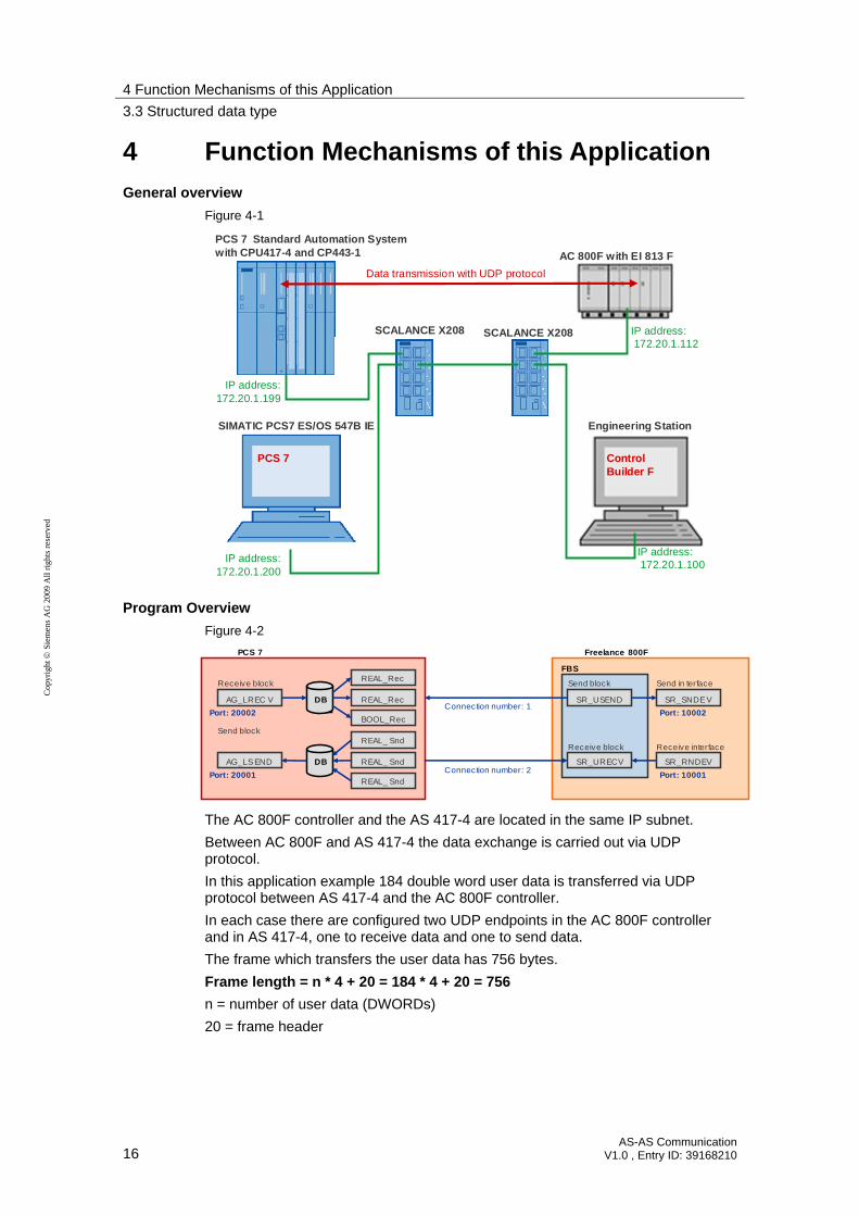
General overview
Figure 4-1
PCS 7 Standard Automation Systemwith CPU417-4 and CP443-1
SIMATIC PCS7 ES/OS 547B IE
SCALANCE X208
AC 800F with EI 813 F
Engineering Station
SCALANCE X208
Data transmission with UDP protocol
ControlBuilder F
PCS 7
IP address:172.20.1.199
IP address:172.20.1.112
IP address:172.20.1.200
IP address:172.20.1.100
Program Overview
Figure 4-2
SR_SNDEV
SR_RNDEV
Send in terface
Receive interface
Freelance 800F
SR_USEND
Send block
SR_URECV
Receive block
FBS
Port: 10002
Port: 10001
AG_LREC V
AG_LSEND
Receive block
Send block
PCS 7
REAL_Rec
REAL_Rec
BOOL_Rec
DB
REAL_ Snd
REAL_ Snd
REAL_ Snd
DB
Port: 20002
Port: 20001
Connection number: 1
Connection number: 2
The AC 800F controller and the AS 417-4 are located in the same IP subnet.
Between AC 800F and AS 417-4 the data exchange is carried out via UDP protocol.
In this application example 184 double word user data is transferred via UDP protocol between AS 417-4 and the AC 800F controller.
In each case there are configured two UDP endpoints in the AC 800F controller and in AS 417-4, one to receive data and one to send data.
The frame which transfers the user data has 756 bytes.
Frame length = n * 4 + 20 = 184 * 4 + 20 = 756
n = number of user data (DWORDs)
20 = frame header

4 Function Mechanisms of this Application
4.1 Freelance 800F process control system
AS-AS Communication V1.0 , Entry ID: 39168210 17
Cop
yrig
ht
Sie
men
s A
G 2
009
All
rig
hts
rese
rved
4.1 Freelance 800F process control system
Figure 4-3
FBS
Name: UDP_Sendlocal port: 10002remote port: 20002Destination IP address: 172.20.199
Name: UDP_Recivelocal port: 10001
SR_SNDEV
SR_RNDEV
Name: Sendy_1Interface name: UDP_SendID of remote receive block: 1
SR_USEND
Name: RecivyInterface name: UDP_ReciveID of receive block: 1
SR_URECV
Name: StrukturData type: Struktur_1
Name: Struktur_RData type: Struktur_2
Variable
Variable
4.1.1 Program details of Freelance 800F process control system
In the AC 800F controller you will use the SR_SNDEV send interface with the SR_USEND send block to send data via the communication module EI 813F. In this application example the data is sent via port 10002 to port 20002 of the AS 417-4.
In the AC 800F controller you will use the SR_RNDEV receive interface with the SR_URECV receive block to receive data via the communication module EI 813F. In this application example the data of the AS 417-4 are received via port 10001.
Make the following settings for the send and receive interface:
a unique name for the send and receive interface has to be assigned.
activate the UDP protocol
IP address of the communication partner (destination station)
local port of send or receive interface
remote port in communication partner (destination station)
In this application example the following settings are used for the "SR_SNDEV" send interface:
Table 4-1
Setting Value Note
Name UDP_Send Note down the name since it has to be entered as interface name when configuring the "SR_USEND" send block.
Local port (Own TCP/IP port)
10002 You have to use different local ports for the send and receive interface. The ports have to be > 10000.
Remote port (TCP/IP port of destination station)
20002
IP address of the communication partner (Internet address of destination station)
172.20.1.199 IP address of CP443-1 in AS 417-4

4 Function Mechanisms of this Application
4.1 Freelance 800F process control system
18 AS-AS Communication
V1.0 , Entry ID: 39168210
Cop
yrig
ht
Sie
men
s A
G 2
009
All
rig
hts
rese
rved
In this application example the following settings are used for the "SR_RNDEV" receive interface:
Table 4-2
Setting Value Note
Name UDP_Recive Note down the name since it has to be entered as interface name when configuring the "SR_URECV" receive block.
Local port (Own TCP/IP port)
10001 You have to use different local ports for the send and receive interface. The ports have to be > 10000.
In this application example the following settings are used for the "SR_USEND" send block:
Table 4-3
Setting Value Note
Name Sendy_1 use unique name
Interface name UDP_Send Name of send interface
Id of remote receive block 1 Connection ID A number between 1 and 255 is requested as ID which clearly assigns the block to the interface.
In this application example the following settings are used for the "SR_URECV" receive block:
Table 4-4
Setting Value Note
Name Recivy use unique name
Interface name UDP_Recive Name of receive interface
Id of receive block 1 Connection ID A number between 1 and 255 is requested as ID which clearly assigns the block to the interface.

4 Function Mechanisms of this Application
4.1 Freelance 800F process control system
AS-AS Communication V1.0 , Entry ID: 39168210 19
Cop
yrig
ht
Sie
men
s A
G 2
009
All
rig
hts
rese
rved
In the AC 800F user program the following variables are created as structured data types:
Table 4-5
Name of variable Data type Note
Struktur Struktur_1 to send data
Struktur_R Struktur_2 to receive data
Summerizing the variables to be transferred in a structured variable type, has the advantage that only one send and receive block is needed. This considerably facilitates the evaluation in the PCS 7 process control system.
In the structured data type "Struktur_1", 184 variables of the REAL data type are summarized. These 184 variables are transferred with the SR_USEND send block.
Table 4-6
Name Type Initial value
sREAL1 REAL 1.0
sREAL2 REAL 2.0
sREAL3 REAL 3.0
sREAL4 REAL 4.0
sREAL5 REAL 5.0
sREAL6 REAL 6.0
sREAL7 REAL 7.0
sREAL8 REAL 8.0
sREAL9 REAL 9.0
sREAL10 REAL 10.0
sREAL11 REAL 1.0
sREAL12 REAL 2.0
…
sREAL184 REAL 4.0
4 Function Mechanisms of this Application
4.2 PCS 7 process control system
20 AS-AS Communication
V1.0 , Entry ID: 39168210
Cop
yrig
ht
Sie
men
s A
G 2
009
All
rig
hts
rese
rved
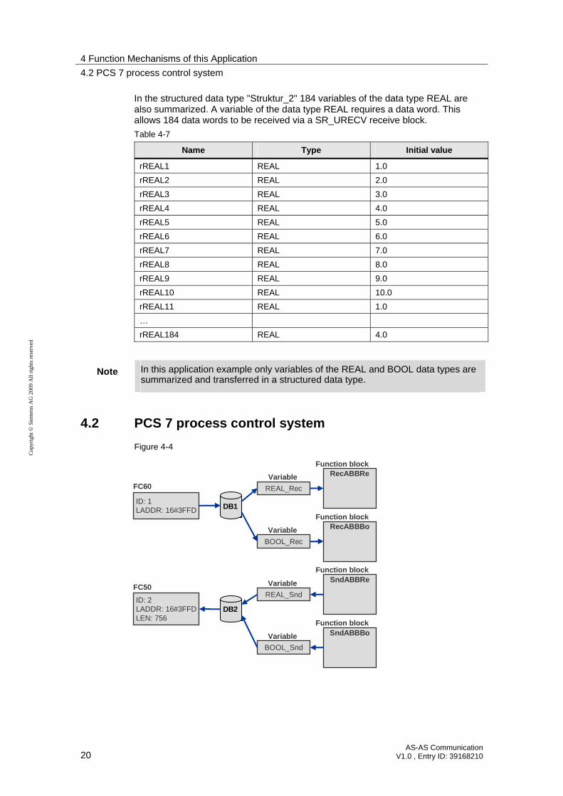
In the structured data type "Struktur_2" 184 variables of the data type REAL are also summarized. A variable of the data type REAL requires a data word. This allows 184 data words to be received via a SR_URECV receive block.
Table 4-7
Name Type Initial value
rREAL1 REAL 1.0
rREAL2 REAL 2.0
rREAL3 REAL 3.0
rREAL4 REAL 4.0
rREAL5 REAL 5.0
rREAL6 REAL 6.0
rREAL7 REAL 7.0
rREAL8 REAL 8.0
rREAL9 REAL 9.0
rREAL10 REAL 10.0
rREAL11 REAL 1.0
…
rREAL184 REAL 4.0
Note In this application example only variables of the REAL and BOOL data types are summarized and transferred in a structured data type.
4.2 PCS 7 process control system
Figure 4-4
ID: 1LADDR: 16#3FFD
ID: 2LADDR: 16#3FFDLEN: 756
FC60
FC50
REAL_Rec
BOOL_Rec
DB1
REAL_Snd
BOOL_Snd
DB2
RecABBRe
RecABBBo
SndABBRe
SndABBBo
Function block
Function block
Function block
Function block
Variable
Variable
Variable
Variable

4 Function Mechanisms of this Application
4.2 PCS 7 process control system
AS-AS Communication V1.0 , Entry ID: 39168210 21
Cop
yrig
ht
Sie
men
s A
G 2
009
All
rig
hts
rese
rved
4.2.1 Program details on user program of AS 417-4
Call the FC50 "AG_LSEND" send block in the user program of AS 417-4 to be able to send data via CP443-1. In this application example the data is send via port 20001 to port 10001 of the AC 800F controller.
Call the FC60 "AG_LRECV" receive block in the user program of AS 417-4 to be able to receive data via CP443-1. In this application example the data from the AC 800F controller is received via port 10002.
The received data is stored in DB1. The data to be sent is stored in DB2.
To make the frame of the Freelance 800F process control system readable in PCS 7, four function blocks have to be created. They contain conversion functions and convert:
data received by Freelance 800F into readable data for PCS7
data to be sent into data readable to Freelance
When converting, attention needs to be paid that a data word (DWORD) may constist of a variable by data type REAL or of 4 variables by data type BOOL.
"RecABBRe" function block
The "RecABBRe" function block converts a received variable of data type REAL.
The variable of the REAL data type has the following structure in Freelance 800F and is read at the IN input parameter of the "RecABBRe" function block:
Figure 4-5
HH byte HL byte LH byte LL byte
DWORD at inputparameter IN
The variable is converted into a format readable to PCS 7. The converted REAL value is transferred at the OUTREAL output.
Figure 4-6
LL byte LH byte HL byte HH byte
REAL at output parameter OUTREAL

4 Function Mechanisms of this Application
4.2 PCS 7 process control system
22 AS-AS Communication
V1.0 , Entry ID: 39168210
Cop
yrig
ht
Sie
men
s A
G 2
009
All
rig
hts
rese
rved
In the "RecABBRe" function block, the following variables are defined:
Table 4-8
Interface Name Data type
IN IN DWord
OUT OUTREAL Real
WORD1 Word
WORD2 Word
LL_Byte Byte
LH_Byte Byte
HL_Byte Byte
STAT
HH_Byte Byte
The received DWORD, a variable of the REAL data type, is divided into four bytes for further processing.
L #IN // load DWORD at IN input parameter
T #LL_Byte // store LL byte of DWORD
L DW#16#FFFFFF00
UD
SRD 8
T #LH_Byte // store LH byte of DWORD
L #IN
L DW#16#FFFF0000
UD
SRD 16
T #HL_Byte // store HL byte of DWORD
L #IN
L DW#16#FF000000
UD
SRD 24
T #HH_Byte // store HH byte of DWORD
The received DWORD is converted into a format readable to PCS 7.
L #LL_Byte
SLD 8
L #LH_Byte
OW
T #WORD1 // LL byte and LH byte are stored in WORD1
L #HL_Byte
SLD 8
L #HH_Byte
OW

4 Function Mechanisms of this Application
4.2 PCS 7 process control system
AS-AS Communication V1.0 , Entry ID: 39168210 23
Cop
yrig
ht
Sie
men
s A
G 2
009
All
rig
hts
rese
rved
T #WORD2 // HL byte and HH byte are stored in WORD2
L #WORD1
SLD 16
L #WORD2
OD
T #OUTREAL
BEA
The REAL value of the OUTREAL output parameter is now composed as follows: LL byte, LH byte, HL byte, HH byte.
"RecABBBo" function block
Four variables of the BOOL data type are transferred as DWORD. The "RecABBBo" function block converts the DWORD into PCS 7 readable BOOL values.
In Freelance 800F the DWORD is structured as follows. The DWORD is read at the IN input parameter of the "RecABBBo" function block:
Figure 4-7
HH byte HL byte LH byte LL byte
BOOL at outputOUTBL_4
DWORD at input IN
BOOL at outputOUTBL_3
BOOL at outputOUTBL_2
BOOL at outputOUTBL_1
The BOOL values filtered out of the DWORD are transmitted at the OUTBL_1, OUTBL_2, OUTBL_3 and OUTBL_4 outputs.
In the "RecABBBo" function block, the following variables are defined:
Table 4-9
Interface Name Data type
IN IN DWord
OUTBL_1 Bool
OUTBL_2 Bool
OUTBL_3 Bool
OUT
OUTBL_4 Bool
WORD1 Word
WORD2 Word
LL_Byte Byte
LH_Byte Byte
HL_Byte Byte
STAT
HH_Byte Byte

4 Function Mechanisms of this Application
4.2 PCS 7 process control system
24 AS-AS Communication
V1.0 , Entry ID: 39168210
Cop
yrig
ht
Sie
men
s A
G 2
009
All
rig
hts
rese
rved
The DWORD, in which four variables of the BOOL data type are transferred byte by byte, is divided into four bytes for further processing.
L #IN // load DWORD at input parameter
T #LL_Byte // store LL byte of DWORD
L DW#16#FFFFFF00
UD
SRD 8
T #LH_Byte // store LH byte of DWORD
L #IN
L DW#16#FFFF0000
UD
SRD 16
T #HL_Byte // store HL byte of DWORD
L #IN
L DW#16#FF000000
UD
SRD 24
T #HH_Byte // store HH byte of DWORD
The received DWORD is converted into PCS 7 readable BOOL values.
L 1
L #LL_Byte
==I
=OUTBL_1
L 1
L #LH_Byte
==I
=OUTBL_2
L 1
L #HL_Byte
==I
=OUTBL_3
L 1
L #HH_Byte
==I
=OUTBL_4
BEA
4 Function Mechanisms of this Application
4.2 PCS 7 process control system
AS-AS Communication V1.0 , Entry ID: 39168210 25
Cop
yrig
ht
Sie
men
s A
G 2
009
All
rig
hts
rese
rved
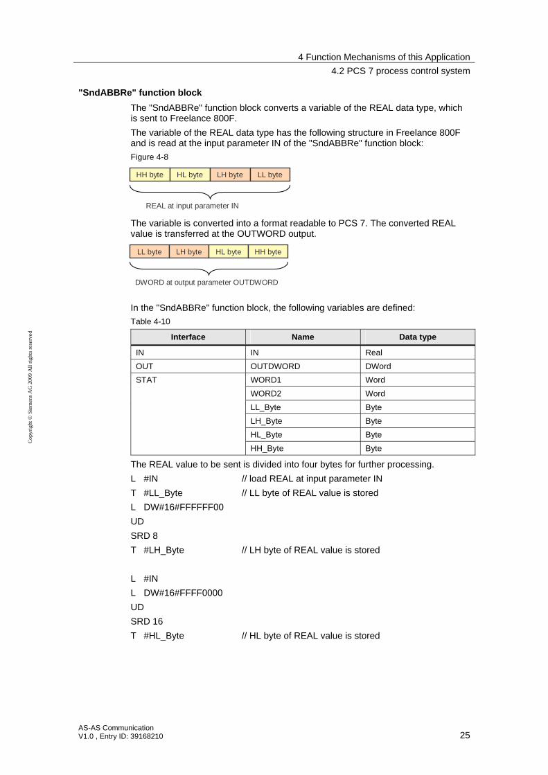
"SndABBRe" function block
The "SndABBRe" function block converts a variable of the REAL data type, which is sent to Freelance 800F.
The variable of the REAL data type has the following structure in Freelance 800F and is read at the input parameter IN of the "SndABBRe" function block:
Figure 4-8
HH byte HL byte LH byte LL byte
REAL at input parameter IN
The variable is converted into a format readable to PCS 7. The converted REAL value is transferred at the OUTWORD output.
LL byte LH byte HL byte HH byte
DWORD at output parameter OUTDWORD
In the "SndABBRe" function block, the following variables are defined:
Table 4-10
Interface Name Data type
IN IN Real
OUT OUTDWORD DWord
WORD1 Word
WORD2 Word
LL_Byte Byte
LH_Byte Byte
HL_Byte Byte
STAT
HH_Byte Byte
The REAL value to be sent is divided into four bytes for further processing.
L #IN // load REAL at input parameter IN
T #LL_Byte // LL byte of REAL value is stored
L DW#16#FFFFFF00
UD
SRD 8
T #LH_Byte // LH byte of REAL value is stored
L #IN
L DW#16#FFFF0000
UD
SRD 16
T #HL_Byte // HL byte of REAL value is stored
4 Function Mechanisms of this Application
4.2 PCS 7 process control system
26 AS-AS Communication
V1.0 , Entry ID: 39168210
Cop
yrig
ht
Sie
men
s A
G 2
009
All
rig
hts
rese
rved
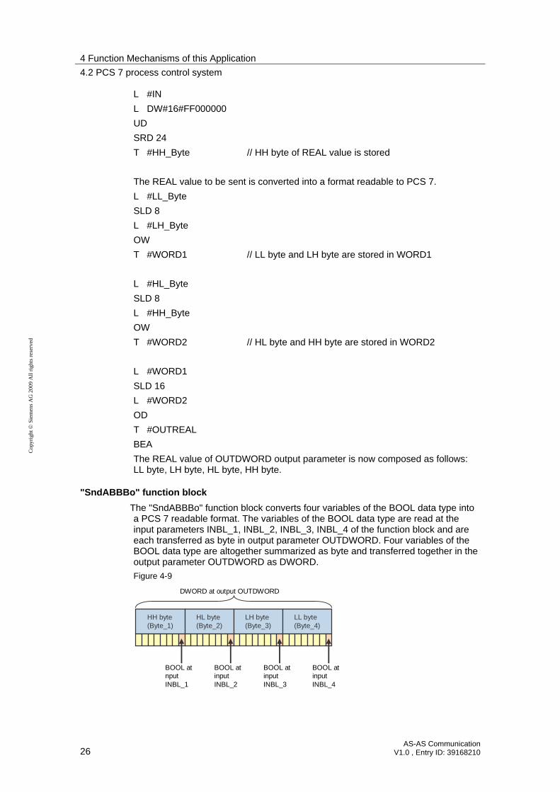
L #IN
L DW#16#FF000000
UD
SRD 24
T #HH_Byte // HH byte of REAL value is stored
The REAL value to be sent is converted into a format readable to PCS 7.
L #LL_Byte
SLD 8
L #LH_Byte
OW
T #WORD1 // LL byte and LH byte are stored in WORD1
L #HL_Byte
SLD 8
L #HH_Byte
OW
T #WORD2 // HL byte and HH byte are stored in WORD2
L #WORD1
SLD 16
L #WORD2
OD
T #OUTREAL
BEA
The REAL value of OUTDWORD output parameter is now composed as follows: LL byte, LH byte, HL byte, HH byte.
"SndABBBo" function block
The "SndABBBo" function block converts four variables of the BOOL data type into a PCS 7 readable format. The variables of the BOOL data type are read at the input parameters INBL_1, INBL_2, INBL_3, INBL_4 of the function block and are each transferred as byte in output parameter OUTDWORD. Four variables of the BOOL data type are altogether summarized as byte and transferred together in the output parameter OUTDWORD as DWORD.
Figure 4-9
HH byte(Byte_1)
HL byte(Byte_2)
LH byte(Byte_3)
LL byte(Byte_4)
BOOL at nputINBL_1
DWORD at output OUTDWORD
BOOL at inputINBL_2
BOOL at inputINBL_3
BOOL at inputINBL_4
4 Function Mechanisms of this Application
4.2 PCS 7 process control system
AS-AS Communication V1.0 , Entry ID: 39168210 27
Cop
yrig
ht
Sie
men
s A
G 2
009
All
rig
hts
rese
rved
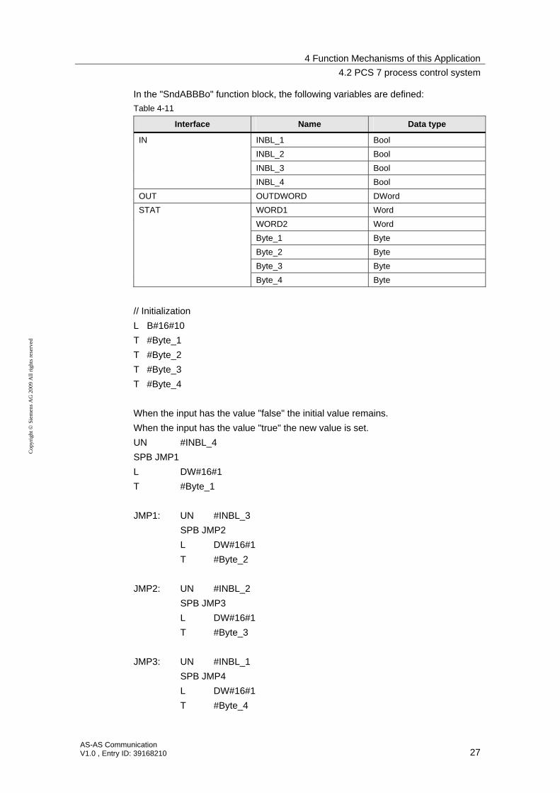
In the "SndABBBo" function block, the following variables are defined:
Table 4-11
Interface Name Data type
INBL_1 Bool
INBL_2 Bool
INBL_3 Bool
IN
INBL_4 Bool
OUT OUTDWORD DWord
WORD1 Word
WORD2 Word
Byte_1 Byte
Byte_2 Byte
Byte_3 Byte
STAT
Byte_4 Byte
// Initialization
L B#16#10
T #Byte_1
T #Byte_2
T #Byte_3
T #Byte_4
When the input has the value "false" the initial value remains.
When the input has the value "true" the new value is set.
UN #INBL_4
SPB JMP1
L DW#16#1
T #Byte_1
JMP1: UN #INBL_3
SPB JMP2
L DW#16#1
T #Byte_2
JMP2: UN #INBL_2
SPB JMP3
L DW#16#1
T #Byte_3
JMP3: UN #INBL_1
SPB JMP4
L DW#16#1
T #Byte_4

4 Function Mechanisms of this Application
4.2 PCS 7 process control system
28 AS-AS Communication
V1.0 , Entry ID: 39168210
Cop
yrig
ht
Sie
men
s A
G 2
009
All
rig
hts
rese
rved
JMP4: L #Byte_1
SLD 8
L #Byte_2
OW
T #WORD1 // Byte_1 and Byte_2 are stored in WORD1
L #Byte_3
SLD 8
L #Byte_4
OW
T #WORD2 // Byte_3 and Byte_4 are stored in WORD2
L #WORD1
SLD 16
L #WORD2
OD
T #OUTDWORD // WORD1 and WORD2 are stored in output OUTDWORD
BEA
The OUTDWORD output parameter is now composed as follows: Byte_1, Byte_2, Byte_3, Byte_4.

5 Configuration Process
5.1 Configuration of the AC 800F controller
AS-AS Communication V1.0 , Entry ID: 39168210 29
Cop
yrig
ht
Sie
men
s A
G 2
009
All
rig
hts
rese
rved
5 Configuration Process
5.1 Configuration of the AC 800F controller
Configuring of the EI 813F communication module
Open the project that contains the configuration of the AC 800F controller in the "Control Builder F" engineering tool.
The EI 813F communication module is configured with the following settings at slot E1 of the AC 800F controller.
Table 5-1
Setting Value
Brief Description Ethernet module 10BaseT
Module type EI813F
Tag name EI813F_2_E1 (Default tag name)
Station position 2
Slot E1
Inserting and configuring send and receive interface
Table 5-2
No. Instruction Comment
1. When you have opened the project with the configuration of the AC 800F controller in the "Control Builder F" engineering tool, then right click the EI 813F communication module and select the Insert menu. The Insert New Object dialog is opened.

5 Configuration Process
5.1 Configuration of the AC 800F controller
30 AS-AS Communication
V1.0 , Entry ID: 39168210
Cop
yrig
ht
Sie
men
s A
G 2
009
All
rig
hts
rese
rved
No. Instruction Comment
2. Select the "SR_SNDEV" Ethernet send interface. Confirm your selection with "OK".
3. Right click the EI 813F communication module and select the Insert menu. The dialog "Insert New Object" is opened.
4. Select the "SR_RNDEV" Ethernet receive interface. Confirm your selection with "OK".

5 Configuration Process
5.1 Configuration of the AC 800F controller
AS-AS Communication V1.0 , Entry ID: 39168210 31
Cop
yrig
ht
Sie
men
s A
G 2
009
All
rig
hts
rese
rved
No. Instruction Comment
5. Configure the send interface. Enter the values according to Table 4-1 and activate the UDP protocol.
Click the Save button to accept the settings and exit the configuration with OK.
6. Configure the receive interface. Enter the values according to Table 4-2 and activate the UDP protocol.
Click the Save button to accept the settings and exit the configuration with OK.
Note The input fields shaded in red are "required entry fields". Those fields have to be filled in.
The settings in the hardware are completed once you have inserted and configured the send and receive interface.

5 Configuration Process
5.1 Configuration of the AC 800F controller
32 AS-AS Communication
V1.0 , Entry ID: 39168210
Cop
yrig
ht
Sie
men
s A
G 2
009
All
rig
hts
rese
rved
Creating and configuring send and receive block
Table 5-3
No Instruction Comment
1. Create a plan in the FBS program (function block).
2. Create a SR_USEND send block via Blocks menu TCP/IP Send and Receive Send module.
3. Configure the send block. Enter the values according to Table 4-3 and activate the Autorequest function (automatic processing). In addition, you can configure an alarm message.
Click the Save button to accept the settings and exit the configuration with OK.
4. Create a SR_URECV receive block via Blocks menu TCP/IP Send and Receive Receive module.

5 Configuration Process
5.1 Configuration of the AC 800F controller
AS-AS Communication V1.0 , Entry ID: 39168210 33
Cop
yrig
ht
Sie
men
s A
G 2
009
All
rig
hts
rese
rved
No Instruction Comment
5. Configure the send block. Enter the values according to Table 4-4. In addition, you can configure an alarm message.
Click the Save button to accept the settings and exit the configuration with OK.
Creating structured data types
Table 5-4
No. Instruction Comment
1. Create a structured data type to send values.
Click the Structured data types button in the menu bar.
2. Right click an empty field and select the menu entry Insert a new data type.
3. Subsequently select the Define menu entry and configure the values in the structure.

5 Configuration Process
5.1 Configuration of the AC 800F controller
34 AS-AS Communication
V1.0 , Entry ID: 39168210
Cop
yrig
ht
Sie
men
s A
G 2
009
All
rig
hts
rese
rved
No. Instruction Comment
4. Define a variable in the plan of the FBS program and interconnect it with the "IN" pin of the "SR_USEND" send block. Doubleclick the variable to open the Insert New Variable dialog. Here you enter a name for the variable and assign the variable to the already specified data type "Struktur_1".
Apply the settings with OK.
5. Now the structured data type is transferred via the send block.
Note Creating and assigning a structured data type for the receive block is carried out the same way as for the send block. The variable is interconnected with the "OUT" pin of the "SR_URECV" receive block.
5 Configuration Process
5.2 Configuration of the AS 417-4 in PCS 7
AS-AS Communication V1.0 , Entry ID: 39168210 35
Cop
yrig
ht
Sie
men
s A
G 2
009
All
rig
hts
rese
rved
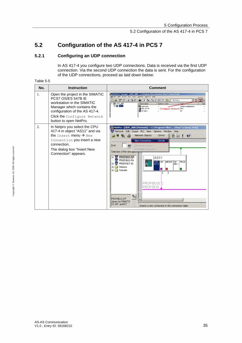
5.2 Configuration of the AS 417-4 in PCS 7
5.2.1 Configuring an UDP connection
In AS 417-4 you configure two UDP connections. Data is received via the first UDP connection. Via the second UDP connection the data is sent. For the configuration of the UDP connections, proceed as laid down below:
Table 5-5
No. Instruction Comment
1. Open the project in the SIMATIC PCS7 OS/ES 547B IE workstation in the SIMATIC Manager which contains the configuration of the AS 417-4.
Click the Configure Network button to open NetPro.
Configure Network
2. In Netpro you select the CPU 417-4 in object "AS11" and via the Insert menu New Connection you insert a new connection. The dialog box "Insert New Connection" appears.
5 Configuration Process
5.2 Configuration of the AS 417-4 in PCS 7
36 AS-AS Communication
V1.0 , Entry ID: 39168210
Cop
yrig
ht
Sie
men
s A
G 2
009
All
rig
hts
rese
rved
No. Instruction Comment
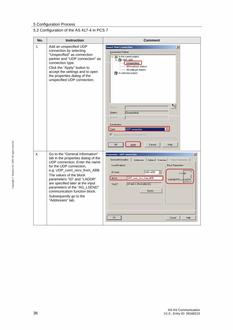
3. Add an unspecified UDP connection by selecting "Unspecified" as connection partner and "UDP connection" as connection type. Click the "Apply" button to accept the settings and to open the properties dialog of the unspecified UDP connection.
4. Go to the "General Information" tab in the properties dialog of the UDP connection. Enter the name for the UDP connection, e.g. UDP_conn_recv_from_ABB The values of the block parameters "ID" and "LADDR" are specified later at the input parameters of the "AG_LSEND" communication function block. Subsequently go to the "Addresses" tab.

5 Configuration Process
5.2 Configuration of the AS 417-4 in PCS 7
AS-AS Communication V1.0 , Entry ID: 39168210 37
Cop
yrig
ht
Sie
men
s A
G 2
009
All
rig
hts
rese
rved
No. Instruction Comment
5. Under Remote IP address enter the IP address 172.20.1.112 of the EI 813F communication module in Freelance 800F. Under Remote port, enter port 10002 that you have defined for the send interface of the EI 813F communication module under "Own TCP/IP-Port". As local port, enter port 20002 which you have already defined for the send interface of the EI 813F communication module under "TCP/IP port of destination station". Confirm the input with OK.
• IP address of the EI 813F communication module in Freelance 800F
• own TCP/IP-Port of the send interface of the EI 813F communication module in Freelance 800F
6. Mark the CPU 417-4 in object "AS11". In the connection table you will see the UDP connection "UDP_conn_recv_from_ABB" to receive the data.
7. Add another unspecified UDP connection. Go to the "General Information" tab in the properties dialog of the UDP connection. Enter a sensible name for the UDP connection, e.g. UDP_conn_send_to_ABB The values of the block parameters "ID" and "LADDR" are specified later at the input parameters of the FC60 "AG_LRECV" communication function block. Subsequently go to the "Addresses" tab.

5 Configuration Process
5.2 Configuration of the AS 417-4 in PCS 7
38 AS-AS Communication
V1.0 , Entry ID: 39168210
Cop
yrig
ht
Sie
men
s A
G 2
009
All
rig
hts
rese
rved
No. Instruction Comment
8. Under Remote IP address enter the IP address 172.20.1.112 of the EI 813F communication module in Freelance 800F. Under Remote port, enter port 10001 which you defined for the receive interface of the EI 813F communication module under "Own TCP/IP-Port". Enter port 20001 as local port. Confirm the entry by clicking "OK". • IP address of the EI 813F communication
module in Freelance 800F
• own TCP/IP-Port of the receive interface of the EI 813F communication module in Freelance 800F
9. Mark the CPU 417-4 in object "AS11". In the connection table you will see two UDP connections:
UDP_conn_recv_from_ABB to receive data
UDP_conn_send_to_ABB to send data
10. Mark the "AS11" object and click the "Save and Compile" button. Subsequently click the "Download" button to load the configuration of the AS 417-4 including the UDP connections into the CPU. Save and Compile Download

5 Configuration Process
5.2 Configuration of the AS 417-4 in PCS 7
AS-AS Communication V1.0 , Entry ID: 39168210 39
Cop
yrig
ht
Sie
men
s A
G 2
009
All
rig
hts
rese
rved
5.2.2 Inserting data blocks
Table 5-6
No. Instruction Comment
1. Open the project of the AS 417-4. In the "AS11" object, navigate to the "Block" entry and select it. Add a new data block (DB) in the user program of AS 417-4 via the Insert menu S7 Block Data Block.
2. Enter a free number and a sensible symbolic name in the properties dialog of the DB. e.g.: DB1 "FROM_ABB"
3. Emulate the frame header in bytes 0-19 of the DB. From byte 20 the user data received by PCS 7 will be saved.

5 Configuration Process
5.2 Configuration of the AS 417-4 in PCS 7
40 AS-AS Communication
V1.0 , Entry ID: 39168210
Cop
yrig
ht
Sie
men
s A
G 2
009
All
rig
hts
rese
rved
No. Instruction Comment
4. The volume of user data that is received by PCS 7 is determined by the number of variables in the structured data of the Freelance 800F process control system.
5. Add another DB in the AS 417-4 user program. Enter a free number and a sensible symbolic name in the properties dialog of the DB. e.g.: DB2 "TO_ABB"
6. Emulate the frame header in bytes 0-19 of the DB. From byte 20 the user data that is to be sent from PCS 7 to Freelance 800F will be saved.

5 Configuration Process
5.2 Configuration of the AS 417-4 in PCS 7
AS-AS Communication V1.0 , Entry ID: 39168210 41
Cop
yrig
ht
Sie
men
s A
G 2
009
All
rig
hts
rese
rved
No. Instruction Comment
7. The volume of user data that is sent from PCS 7 to Freelance 800F is determined by the number of variables in PCS 7. The structured data type of the Freelance 800F process control system has to be adjusted accordingly.
Note Copy the frame header of the receive data block in Online mode into the frame header of the send block. Doing this updates the send and receive interface of ABB and it does not have to be updated manually.
5.2.3 Calling and configuring the communication function blocks FC50 "AG_LSEND" and FC60 "AG_LRECV"
Overview FC60 "AG_LRECV"
Figure 5-1
AG_LRECV
ID
LADDR
RECV
NDR
ERROR
STATUS
LEN
INT
WORD
ANY
BOOL
BOOL
WORD
INT
Input parameters FC60 "AG_LRECV"
Table 5-7
Input parameters Data type Description
ID INT The parameter ID specifies the connection number of the configured communication connection.
LADDR WORD Module start address
RECV ANY Specifying address and length of receive data area The address of the data area alternatively refers to:
data area
memory area

5 Configuration Process
5.2 Configuration of the AS 417-4 in PCS 7
42 AS-AS Communication
V1.0 , Entry ID: 39168210
Cop
yrig
ht
Sie
men
s A
G 2
009
All
rig
hts
rese
rved
Output parameters FC60 "AG_LRECV"
Table 5-8
Output parameters Data type Description
NDR BOOL The parameter indicates whether new data has been accepted 0: - 1: New data
ERROR BOOL Error display 0: - 1: Error when receiving the data
STATUS WORD Status display
LEN INT Indicates the number of bytes which were adopted in the receive data area.
Overview FC50 "AG_SEND"
Figure 5-2
AG_LSEND
ID
LADDR
SEND
DONE
ERROR
STATUS
INT
WORD
ANY
BOOL
BOOL
WORD
BOOL ACT
INT LEN
Input parameters FC50 "AG_LSEND"
Table 5-9
Input parameters Data type Description
ACT BOOL Job trigger 1: Data is sent from the send buffer indicated 0: Status displays DONE, ERROR and STATUS are updated
ID INT The parameter ID specifies the connection number of the configured communication connection.
LADDR WORD Module start address
SEND ANY Specifying address and length of send data area The address of the data area alternatively refers to:
data area
memory area
LEN INT Number of bytes which are to be transmitted by the job from the indicated send data area.

5 Configuration Process
5.2 Configuration of the AS 417-4 in PCS 7
AS-AS Communication V1.0 , Entry ID: 39168210 43
Cop
yrig
ht
Sie
men
s A
G 2
009
All
rig
hts
rese
rved
Output parameters FC50 "AG_LSEND"
Table 5-10
Output parameters Data type Description
DONE BOOL The parameter indicates whether the job has been processed without errors. No other job can be triggered as long as DONE=0 0: Job running 1: Job completed
ERROR BOOL Error display 0: - 1: Error when sending the data
STATUS WORD Status display
5 Configuration Process
5.2 Configuration of the AS 417-4 in PCS 7
44 AS-AS Communication
V1.0 , Entry ID: 39168210
Cop
yrig
ht
Sie
men
s A
G 2
009
All
rig
hts
rese
rved
Calling and configuring the communication function blocks
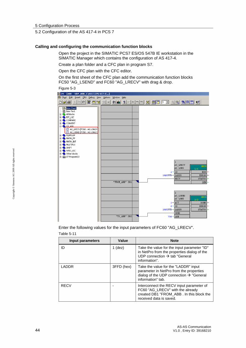
Open the project in the SIMATIC PCS7 ES/OS 547B IE workstation in the SIMATIC Manager which contains the configuration of AS 417-4.
Create a plan folder and a CFC plan in program S7.
Open the CFC plan with the CFC editor.
On the first sheet of the CFC plan add the communication function blocks FC50 "AG_LSEND" and FC60 "AG_LRECV" with drag & drop.
Figure 5-3
Enter the following values for the input parameters of FC60 "AG_LRECV".
Table 5-11
Input parameters Value Note
ID 1 (dez) Take the value for the input parameter "ID" in NetPro from the properties dialog of the UDP connection tab "General information".
LADDR 3FFD (hex) Take the value for the "LADDR" input parameter in NetPro from the properties dialog of the UDP connection "General information" tab.
RECV - Interconnect the RECV input parameter of FC60 "AG_LRECV" with the already created DB1 "FROM_ABB . In this block the received data is saved.
5 Configuration Process
5.2 Configuration of the AS 417-4 in PCS 7
AS-AS Communication V1.0 , Entry ID: 39168210 45
Cop
yrig
ht
Sie
men
s A
G 2
009
All
rig
hts
rese
rved
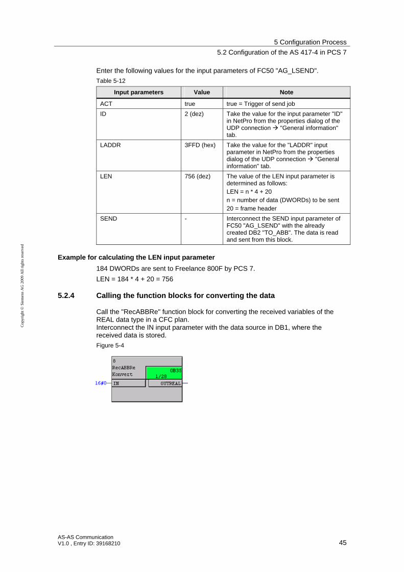
Enter the following values for the input parameters of FC50 "AG_LSEND".
Table 5-12
Input parameters Value Note
ACT true true = Trigger of send job
ID 2 (dez) Take the value for the input parameter "ID" in NetPro from the properties dialog of the UDP connection "General information" tab.
LADDR 3FFD (hex) Take the value for the "LADDR" input parameter in NetPro from the properties dialog of the UDP connection "General information" tab.
LEN 756 (dez) The value of the LEN input parameter is determined as follows: LEN = n * 4 + 20 n = number of data (DWORDs) to be sent 20 = frame header
SEND - Interconnect the SEND input parameter of FC50 "AG_LSEND" with the already created DB2 "TO_ABB". The data is read and sent from this block.
Example for calculating the LEN input parameter
184 DWORDs are sent to Freelance 800F by PCS 7.
LEN = 184 * 4 + 20 = 756
5.2.4 Calling the function blocks for converting the data
Call the "RecABBRe" function block for converting the received variables of the REAL data type in a CFC plan. Interconnect the IN input parameter with the data source in DB1, where the received data is stored.
Figure 5-4

5 Configuration Process
5.2 Configuration of the AS 417-4 in PCS 7
46 AS-AS Communication
V1.0 , Entry ID: 39168210
Cop
yrig
ht
Sie
men
s A
G 2
009
All
rig
hts
rese
rved
Call the "RecABBRo" function block for converting the received variables from the BOOL data type in a CFC plan. Interconnect the following input parameters with the data source in DB1, where the received data is stored.
INBL_1
INBL_2
INBL_3
INBL_4
Figure 5-5
Call the "SndABBRe" function block for converting the received variables from the REAL data type in a CFC plan. Interconnect the IN input parameter with the data source in DB2 where the data to be sent to Freelance 800F, is stored.
Figure 5-6
Call the "SndABBRo" function block for converting the received variables from the REAL data type in a CFC plan. Interconnect the IN input parameter with the data source in DB2 where the data to be sent to Freelance 800F, is stored.
Figure 5-7

6 Installation
6.1 Installation of the hardware
AS-AS Communication V1.0 , Entry ID: 39168210 47
Cop
yrig
ht
Sie
men
s A
G 2
009
All
rig
hts
rese
rved
6 Installation
6.1 Installation of the hardware
The figure below shows the hardware configuration of the application:
Figure 6-1
IP address:172.20.1.199
IP address:172.20.1.200
PCS7 Standard Automation System withCPU417-4 and CP443-1
SIMATIC PCS7 OS/ES 547B IE
SCALANCE X208
AC 800F with EI 813 F
Engineering Station
SCALANCE X208 IP address:172.20.1.112
IP address:172.20.1.100
PCS 7 Process Control System Freelance 800F Process Control System
For details on the hardware components, please refer to chapter 2.3 Hardware and software components used.
The table below gives an overview of the IP addresses as well as the devices which are used in the hardware setup of the application.
Table 6-1
Device IP Address
CP443-1 in AS 417-4 172.20.1.199
EI 813F in AC 800F controller 172.20.1.112
SIMATIC PCS 7 OS/ES 547B IE 172.20.1.200
Engineering Station Freelance 800F 172.20.1.100
Note The setup guidelines for PCS 7 must always be followed. Further information on installation guidelines for PCS 7 can be found in the "SIMATIC Process Control System PCS 7 Compendium Part A - Configuration Guidelines" manual. This is available as a download via the following link:
http://support.automation.siemens.com/WW/view/en/35016996
6.2 Installation of the software
In the manual "SIMATIC Process Control System PCS 7 V7.0 SP1 PC Configuration and Authorization" you will find information on installing PCS 7. This is available as a download via the following link:
http://support.automation.siemens.com/WW/view/en/27002558
7 Startup of the Application
7.1 Commissioning the application in PCS 7
48 AS-AS Communication
V1.0 , Entry ID: 39168210
Cop
yrig
ht
Sie
men
s A
G 2
009
All
rig
hts
rese
rved
7 Startup of the Application
7.1 Commissioning the application in PCS 7
When commissioning the application in PCS 7 proceed as follows.
Set IP address and PG/PC interface of the SIMATIC PCS7 OS/ES 547B IE workstation
Table 7-1
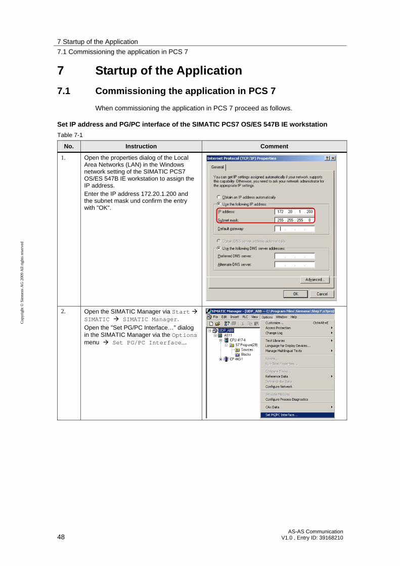
No. Instruction Comment
1. Open the properties dialog of the Local Area Networks (LAN) in the Windows network setting of the SIMATIC PCS7 OS/ES 547B IE workstation to assign the IP address. Enter the IP address 172.20.1.200 and the subnet mask und confirm the entry with "OK".
2. Open the SIMATIC Manager via Start SIMATIC SIMATIC Manager.
Open the "Set PG/PC Interface…" dialog in the SIMATIC Manager via the Options menu Set PG/PC Interface….

7 Startup of the Application
7.1 Commissioning the application in PCS 7
AS-AS Communication V1.0 , Entry ID: 39168210 49
Cop
yrig
ht
Sie
men
s A
G 2
009
All
rig
hts
rese
rved
No. Instruction Comment
3. Under "Interface Parameter Assignment Used" select the following entry: TCP/IP <Network card> Confirm your selection by clicking OK.

7 Startup of the Application
7.1 Commissioning the application in PCS 7
50 AS-AS Communication
V1.0 , Entry ID: 39168210
Cop
yrig
ht
Sie
men
s A
G 2
009
All
rig
hts
rese
rved
Setting IP address of CP443-1 in AS 417-4
Table 7-2
No. Instruction Comment
1. Open the "Set PG/PC interface…" dialog in the SIMATIC Manager via the PLC menu Edit Ethenet Node….
2. Click the "Browse..." button to search your network for accessible nodes. Select the MAC address of the CP443-1 and enter the IP address 172.20.1.199 and subnet mask 255.255.255.0 for the CP443-1 in the "Edit Ethernet Node" dialog. Click the "Assign IP Configuration" button to assign the IP address and the subnet mask just entered to the CP443-1. Click the "Close" button to exit the "Edit Ethernet Node" dialog.

7 Startup of the Application
7.1 Commissioning the application in PCS 7
AS-AS Communication V1.0 , Entry ID: 39168210 51
Cop
yrig
ht
Sie
men
s A
G 2
009
All
rig
hts
rese
rved
Load hardware configuration and user program of AS 417-4
Table 7-3
No. Instruction Comment
1. Open the properties dialog of the Industrial Ethernet Interface of the CP443-1 in the hardware configuration of the AS 417-4. In the "General" tab, click the "Properties..." button. The "Properties – Ethernet interface PN-IO" dialog is opened.
2. In the "Properties – Ethernet interface PN-IO" dialog "General" tab enter the IP address 172.20.1.199 and the subnet mask 255.255.255.0 which you have already assigned to CP443-1. Assign a subnet to CP443-1. If there is no subnet yet, click the "New…" button and create a new subnet. Apply the settings with OK.
3. Save and compile the configuration of AS 417-4. Subsequently load the configuration in the CPU of the AS 417-4.
Save and Compile
Download
Once the configuration of the AS 417-4 is completed, load the user program into the CPU of the AS 417-4.

7 Startup of the Application
7.2 Commissioning the application in the Freelance 800F process control system
52 AS-AS Communication
V1.0 , Entry ID: 39168210
Cop
yrig
ht
Sie
men
s A
G 2
009
All
rig
hts
rese
rved
7.2 Commissioning the application in the Freelance 800F process control system
When commissioning the application in the Freelance 800F process control system proceed as follows.
Setting IP address and PG/PC interface of the engineering station
Table 7-4
No. Instruction Comment
1. Open the properties dialog of the Local Area Networks (LAN), to set the IP address of the engineering station in the Windows network settings of the engineering station in the Freelance 800F process control system. Enter the IP address 172.20.1.100 and the subnet mask.
2. Select the Start menu Programs ABB Industrial IT Freelance 800F Vx.x Configure.
In the General Settings menu enter the IP address 172.20.1.100 and the subnet mask 255.255.255.0 of the engineering station in the Freelance 800F process control system.

7 Startup of the Application
7.2 Commissioning the application in the Freelance 800F process control system
AS-AS Communication V1.0 , Entry ID: 39168210 53
Cop
yrig
ht
Sie
men
s A
G 2
009
All
rig
hts
rese
rved
No. Instruction Comment
3. Open the engineering tool "Control Builder F" via Start Programs ABB Industrial IT Freelance 800F Vx.x.
Select the Project menu Network… to open the Network Configuration dialog.
4. Selet type AC800F. Click the Edit button to open the Network Configuration AC800F2 dialog.
5. Enter the IP address 172.20.1.112 of the AC 800F controller.

7 Startup of the Application
7.2 Commissioning the application in the Freelance 800F process control system
54 AS-AS Communication
V1.0 , Entry ID: 39168210
Cop
yrig
ht
Sie
men
s A
G 2
009
All
rig
hts
rese
rved
No. Instruction Comment
6. Verify all settings made in Project menu Check all.
7. Right click the AC800F controller in the engineering tool "Control Builder F" and select the Load menu Changed objects, to load the settings.

8 Operation of the Application
8.1 Operation of the application in PCS 7
AS-AS Communication V1.0 , Entry ID: 39168210 55
Cop
yrig
ht
Sie
men
s A
G 2
009
All
rig
hts
rese
rved
8 Operation of the Application
8.1 Operation of the application in PCS 7
Monitoring receive data in the variable table
Table 8-1
No. Instruction Comment
1. Add another variable table in the AS 417-4 user program.
2. Add the receive data area for monitoring via the Insert menu Range of Variables….
3. 756 bytes are defined as receive data area in DB1 from address 0 onward. Via the variable table you can monitor the receive data area and therefore the data received by ABB (header frame and user data). The user data received is saved in DB1 from address 20 onwards.

8 Operation of the Application
8.1 Operation of the application in PCS 7
56 AS-AS Communication
V1.0 , Entry ID: 39168210
Cop
yrig
ht
Sie
men
s A
G 2
009
All
rig
hts
rese
rved
Controlling send data via the variable table
Table 8-2
No. Instruction Comment
1. Set the input parameter ACT=1 at FC50 "AG_LSEND".
The send job is triggered or excecuted.
2. Add another variable table in the AS 417-4 user program.
3. Add the send data area for controlling the send data via the Insert menu Range of Variables….
4. 756 bytes are defined as send data area in DB2 from address 0 onward. Via the variable table you can control the data (header frame and user data) to be sent to ABB. The user data to be sent is saved in DB2 from address 20.
Activate modify values

8 Operation of the Application
8.2 Operation of the application in the Freelance 800F process control system
AS-AS Communication V1.0 , Entry ID: 39168210 57
Cop
yrig
ht
Sie
men
s A
G 2
009
All
rig
hts
rese
rved
8.2 Operation of the application in the Freelance 800F process control system
Table 8-3
No. Instruction Comment
1. In the engineering tool "Control Builder F" go to the commissioning mode via Project menu Commissioning.
2. Select the FBS program with a send or receive block in project tree.
Subsequently open the Define Debug Windows dialog via the Windows menu Define debug windows….
3. At first the dialog is empty. Doubleclick the respective variable in the plan which you would like to add.
8 Operation of the Application
8.2 Operation of the application in the Freelance 800F process control system
58 AS-AS Communication
V1.0 , Entry ID: 39168210
Cop
yrig
ht
Sie
men
s A
G 2
009
All
rig
hts
rese
rved
No. Instruction Comment
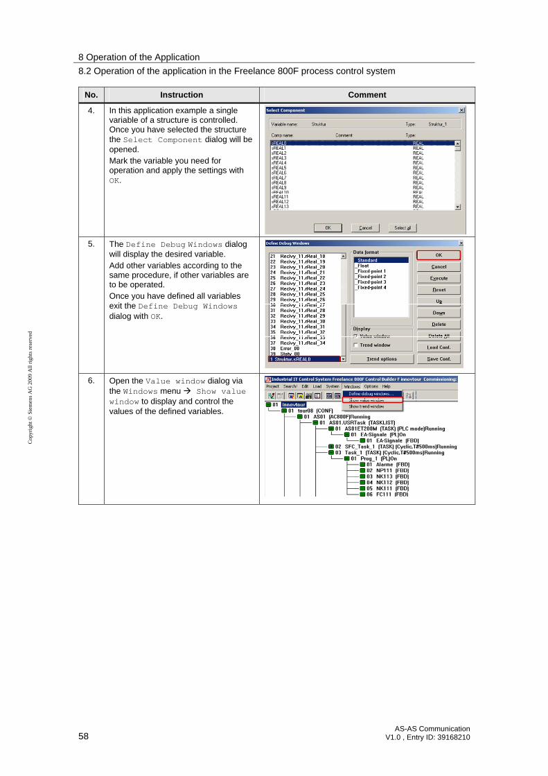
4. In this application example a single variable of a structure is controlled. Once you have selected the structure the Select Component dialog will be opened. Mark the variable you need for operation and apply the settings with OK.
5. The Define Debug Windows dialog will display the desired variable. Add other variables according to the same procedure, if other variables are to be operated. Once you have defined all variables exit the Define Debug Windows dialog with OK.
6. Open the Value window dialog via the Windows menu Show value window to display and control the values of the defined variables.

8 Operation of the Application
8.2 Operation of the application in the Freelance 800F process control system
AS-AS Communication V1.0 , Entry ID: 39168210 59
Cop
yrig
ht
Sie
men
s A
G 2
009
All
rig
hts
rese
rved
No. Instruction Comment
7. The defined variables are displayed with the current value. Doubleclick the variable to change the value.
8. Enter the new value and apply the settings with OK.
9 Related Literature
60 AS-AS Communication
V1.0 , Entry ID: 39168210
Co
pyr
igh
t
Sie
me
ns
AG
20
09
All
righ
ts r
ese
rve
d
9 Related Literature
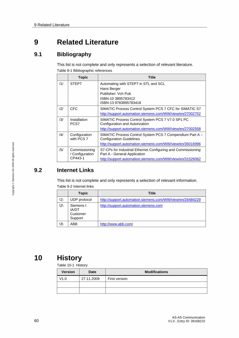
9.1 Bibliography
This list is not complete and only represents a selection of relevant literature.
Table 9-1 Bibliographic references
Topic Title
/1/ STEP7 Automating with STEP7 in STL and SCL Hans Berger Publisher: Vch Pub ISBN-10 3895783412 ISBN-13 9783895783418
/2/ CFC SIMATIC Process Control System PCS 7 CFC for SIMATIC S7 http://support.automation.siemens.com/WW/view/en/27002752
/3/ Installation PCS7
SIMATIC Process Control System PCS 7 V7.0 SP1 PC Configuration and Autorization http://support.automation.siemens.com/WW/view/en/27002558
/4/ Configuration with PCS 7
SIMATIC Process Control System PCS 7 Compendium Part A – Configuration Guidelines http://support.automation.siemens.com/WW/view/en/35016996
/5/ Commissioning/ Configuration CP443-1
S7-CPs for Industrial Ethernet Configuring and Commissioning Part A - General Application http://support.automation.siemens.com/WW/view/en/31526062
9.2 Internet Links
This list is not complete and only represents a selection of relevant information.
Table 9-2 Internet links
Topic Title
\1\ UDP protocol http://support.automation.siemens.com/WW/view/en/26484229
\2\ Siemens I IA/DT Customer Support
http://support.automation.siemens.com
\3\ ABB http://www.abb.com/
10 History Table 10-1 History
Version Date Modifications
V1.0 27.11.2009 First version