applications pp a - parajumpers jacka hos miinto.se ..._batteries_v01.pdffigure 1:battery pack...
TRANSCRIPT
App
licat
ion
Not
e 07
Li-Ion batteries in GSM applications Solutions for Innovative Mobile Telecommunications Siemens Cellular Engines Version: 01 DocID: WM_AN_07_Li+_Batteries_v01

Application Note 07: Li-Ion batteries in GSM applications Confidential/Released s
mo b i l e
WM_AN_07_Li+_Batteries_v01 Page 2 of 16 19.05.2004
Application Note 07: Li-Ion batteries in GSM applications Supported products: Siemens Cellular Engines Version: 01 Date: May 19, 2004 DocId: WM_AN_07_Li+_Batteries_v01 Status: Confidential/Released
General Notes Product is deemed accepted by recipient and is provided without interface to recipient’s products. The documentation and/or product are provided for testing, evaluation, integration and information purposes. The documentation and/or product are provided on an “as is” basis only and may contain deficiencies or inadequacies. The documentation and/or product are provided without warranty of any kind, express or implied. To the maximum extent permitted by applicable law, Siemens further disclaims all warranties, including without limitation any implied warranties of merchantability, completeness, fitness for a particular purpose and non-infringement of third-party rights. The entire risk arising out of the use or performance of the product and documentation remains with recipient. This product is not intended for use in life support appliances, devices or systems where a malfunction of the product can reasonably be expected to result in personal injury. Applications incorporating the described product must be designed to be in accordance with the technical specifications provided in these guidelines. Failure to comply with any of the required procedures can result in malfunctions or serious discrepancies in results. Furthermore, all safety instructions regarding the use of mobile technical systems, including GSM products, which also apply to cellular phones must be followed. Siemens or its suppliers shall, regardless of any legal theory upon which the claim is based, not be liable for any consequential, incidental, direct, indirect, punitive or other damages whatsoever (including, without limitation, damages for loss of business profits, business interruption, loss of business information or data, or other pecuniary loss) arising out the use of or inability to use the documentation and/or product, even if Siemens has been advised of the possibility of such damages. The foregoing limitations of liability shall not apply in case of mandatory liability, e.g. under the German Product Liability Act, in case of intent, gross negligence, injury of life, body or health, or breach of a condition which goes to the root of the contract. However, claims for damages arising from a breach of a condition, which goes to the root of the contract, shall be limited to the foreseeable damage, which is intrinsic to the contract, unless caused by intent or gross negligence or based on liability for injury of life, body or health. The above provision does not imply a change on the burden of proof to the detriment of the recipient. Subject to change without notice at any time. The interpretation of this general note shall be governed and construed according to German law without reference to any other substantive law. Copyright Transmittal, reproduction, dissemination and/or editing of this document as well as utilization of its contents and communication thereof to others without express authorization are prohibited. Offenders will be held liable for payment of damages. All rights created by patent grant or registration of a utility model or design patent are reserved. Copyright © Siemens AG 2004

Application Note 07: Li-Ion batteries in GSM applications Confidential/Released s
mo b i l e
WM_AN_07_Li+_Batteries_v01 Page 3 of 16 19.05.2004
Contents
1 Introduction ...................................................................................................................5 1.1 Related documents................................................................................................5 1.2 Approval considerations ........................................................................................5 1.3 Terms and abbreviations .......................................................................................5
2 Requirements to the battery ........................................................................................6 2.1 Minimum battery requirements for charging ..........................................................7 2.2 Minimum battery requirements for discharging......................................................8 2.3 Charger requirements............................................................................................8
3 Current loads in GSM applications .............................................................................9 3.1 Transmitting current burst......................................................................................9 3.2 Peak current depending on antenna load............................................................10
4 Typical properties of Li+ Batteries and its effects...................................................11 4.1 Effects of the application power supply resistance ..............................................11 4.2 Recovery voltage .................................................................................................12 4.3 Temperature effects.............................................................................................13
5 Construction hints ......................................................................................................14 5.1 Reduced resistance between battery and module...............................................14
6 Implemented charging technique..............................................................................15
7 Siemens support for battery parameterization ........................................................16

Application Note 07: Li-Ion batteries in GSM applications Confidential/Released s
mo b i l e
WM_AN_07_Li+_Batteries_v01 Page 4 of 16 19.05.2004
Figures Figure 1:Battery pack circuit diagram.......................................................................................6 Figure 2: Current at Power Control Level 5..............................................................................9 Figure 3: Current at Power Control Level 19............................................................................9 Figure 4: Typical current consumption for GSM 900, PCL 5, 10, 15, 19................................10 Figure 5:Voltage of a typical 1000mAh Li+ battery under discharge at 20°C.........................11 Figure 6: Recovery voltage and voltage drops of a typical Li+ battery @ GSM PCL5 load ...12 Figure 7: Voltage @ different temperatures of a 1000mAh Li+ battery..................................13 Figure 8: Charging process (quality representation) ..............................................................15
Tables Table 1: Specifications of recommended battery pack.............................................................7 Table 2:Requirements to the battery in charging process........................................................7 Table 3: Requirements to the battery in discharging (calling) process.....................................8 Table 4: Typical resistance of a power supply line.................................................................11 Table 5: Measured resistance and voltage drops of a typical 1000mAh battery....................12 Table 6: Measured battery under temperature influence .......................................................14 Table 7: Typical values of a battery application at 2A current burst.......................................14

Application Note 07: Li-Ion batteries in GSM applications Confidential/Released s
mo b i l e
WM_AN_07_Li+_Batteries_v01 Page 5 of 16 19.05.2004
1 Introduction This application note provides technical recommendations for integrating battery accessories into cellular applications based on Siemens GSM modules. Chapter 2 briefly describes the requirements on batteries. The document focuses on various important points of mind for typical design approaches and general issues regarding battery equipment.
1.1 Related documents
[1] Hardware Interface Description of your Siemens wireless module [2] AT Command Set for your Siemens Wireless module [3] Release Notes related to the firmware of your Siemens wireless module [4] Application Note 16: Updating Firmware The latest product information and technical documents are ready for download on the Siemens Website or may be obtained from your local dealer or the Siemens Sales department. To visit the Siemens Website you can use the following link: http://www.siemens.com/wm
1.2 Approval considerations
The Siemens GSM modules listed above have been type approved for use with the Siemens reference setup. When designing a GSM application you are advised to make sure whether or not the final product is standard compliant. This is particularly important for mobile phones, PDAs or other handheld transmitters and receivers incorporating a GSM module. Depending on the individual design, such devices may require additional Type Approval. Outside of Europe, there may be further international, national or government standards and regulations to be observed for type approval.
1.3 Terms and abbreviations
Abbreviation Meaning
GSM Global System for Mobile Communication
HID Hardware Interfaces Description
PCB Printed Circuit Board
RF Radio Frequency
Vbat Battery Voltage
Li+ battery rechargeable Lithium Ion or Lithium polymer battery

Application Note 07: Li-Ion batteries in GSM applications Confidential/Released s
mo b i l e
WM_AN_07_Li+_Batteries_v01 Page 6 of 16 19.05.2004
2 Requirements on the battery For use of Li+ batteries in mobile applications together with Siemens GSM engines, the battery must fulfill requirements to warrant a proper, long-lasting and high quality operation. Siemens GSM modules provide control of trickle, fast and final charging management of Li+ batteries. For complete support of charging management an external charging circuit is needed for some GSM engines (refer to [1]). The charging algorithm has been optimized for a Li+ battery pack that meets the characteristics listed below. It is recommended that the battery pack you want to integrate into your application is compliant with these specifications. The Li+ battery pack must be specified for a maximum charging voltage of 4.2V. Since charging and discharging largely depend on the battery temperature, the battery pack should include an NTC resistor for battery recognition and temperature observation. If the NTC is not inside the battery, it must be at least in thermal contact with the battery. The charging process will not start if the NTC is not present. Ensure that the pack incorporates a protection circuit capable of detecting overvoltage (protection against overcharging), undervoltage (protection against deep discharging) and overcurrent. The circuit must be insensitive to pulsed current. The internal resistance of the battery and the protection should be as low as possible. It is recommended not to exceed 150mΩ, even under extreme conditions at low temperature. The battery pack must be approved to satisfy the requirements of CE conformity. Figure 1 shows the circuit diagram of a typical battery pack design including the protection elements described above.
Figure 1:Battery pack circuit diagram
to BATT_TEMP to GND
NTC
Polyfuse
ϑ
Protection Circuit
+ -
Battery cell
to BATT+

Application Note 07: Li-Ion batteries in GSM applications Confidential/Released s
mo b i l e
WM_AN_07_Li+_Batteries_v01 Page 7 of 16 19.05.2004
The recommended battery pack in Table 1 has been designed specifically for use with Siemens GSM modules. Table 1: Specifications of recommended battery pack
Battery type Li-Ion
Nominal voltage 3.6V
Capacity 800mAh
NTC 10kΩ ± 5% @ 25°C, B (25/85)=3435K ± 3%
Overcharge detection voltage 4.325 ± 0.025V
Overcharge release voltage 4.075 ± 0.025V
Overdischarge detection voltage 2.5 ± 0.05V
Overdischarge release voltage 2.9 ± 0.5V
Overcurrent detection 3 ± 0.5A
Nominal working current <5µA
Current of low voltage detection 0.5µA
Overcurrent detection delay time 8~16ms
Short detection delay time 50µs
Overdischarge detection delay time 31~125ms
Overcharge detection delay time 1s
Internal resistance <130mΩ
Dimensions 8 x 25 x 40mm
2.1 Minimum battery requirements for charging
When using a different type of battery, the specification given in Table 1 must be fulfilled, especially the requirements for charging. Table 2:Requirements to the battery in charging process
Maximum charging voltage 4.2V
Maximum fast charging Current 500mA
NTC 10kΩ ± 5% @ 25°C, B (25/85)=3435K ± 3%
Charging temperature range 0...45°C
Overcharge detection voltage 4.3 ± 0.025V
Overcharge detection delay time >100ms
Internal resistance <150mΩ Failure to comply with these specifications might cause • the charging process not to start • a premature termination of charging • a short battery lifetime or a destroyed battery See also Chapter 4.1 and 4.3 for more details.

Application Note 07: Li-Ion batteries in GSM applications Confidential/Released s
mo b i l e
WM_AN_07_Li+_Batteries_v01 Page 8 of 16 19.05.2004
2.2 Minimum battery requirements for discharging
When a GSM call or a GPRS connection is established, the battery is discharged by a current profile according to the GSM (GPRS) transmitting and receiving bursts. At best condition the transmit current burst rises up to 2A when the module is transmitting at EGSM900 / Power Level (PCL) 5. The current burst might even reach 3A at worst case condition e.g. bad antenna matching. In order to use the full battery capacity the battery should meet the following requirements for discharging. Table 3: Requirements to the battery in discharging (calling) process
NTC 10kΩ ± 5% @ 25°C, B (25/85)=3435K ± 3%
Overdischarge detection voltage <3.0V
Overdischarge detection delay time 31~125ms
Overcurrent detection 3 ± 0.5A
Overcurrent detection delay time >1ms
Discharging temperature range -20...60°C
Internal resistance <130mΩ See also chapter 4.1 and 4.2 for more details.
2.3 Charger requirements
If you are using the implemented charging technique the charger must be designed to meet the following requirements regarding simple transformer plug or an AC/DC converter: - Output voltage: 5.5V...8V (under load) - The charging current must be limited to max. 500mA1) - Voltage spikes that may occur while you connect the charger must be limited to a
maximum of 10V and must not exceed 1ms - When the charging current is switched off by the module a voltage peak of 10V is allowed
for a maximum of 1ms - There must not be any capacitor on the secondary side of the power plug (avoidance of
current spikes while charge current is pulsed) - When the current is switched on by the module a spike of 1.6A for 1ms shall not be
exceeded 1) This requirement results from possible short time overvoltage at battery pins for a given charging voltage and inner resistance.

Application Note 07: Li-Ion batteries in GSM applications Confidential/Released s
mo b i l e
WM_AN_07_Li+_Batteries_v01 Page 9 of 16 19.05.2004
3 Current loads in GSM applications
3.1 Transmitting current burst
Due to the maximum RF power level of approximately 2W, the battery discharge current is modulated at 2 A (approx.) pulses of 0.577 ms every 4.6 ms. During the low current period, the current consumption during a GSM call is about 70 mA. The current profile is illustrated in Figure 2 and Figure 3. The measured values refer to the GSM band 900 MHz at maximum power level (PCL 5) and minimum power level (PCL 19) with a real 50Ω load. These values may increase up to 2...3A with a badly matching antenna.
Figure 2: Current at Power Control Level 5
Figure 3: Current at Power Control Level 19
Depending on the overall power supply resistance, the corresponding voltage drops measured at the module´s connector may reach higher values.
Application Note 07: Li-Ion batteries in GSM applications Confidential/Released s
mo b i l e
WM_AN_07_Li+_Batteries_v01 Page 10 of 16 19.05.2004
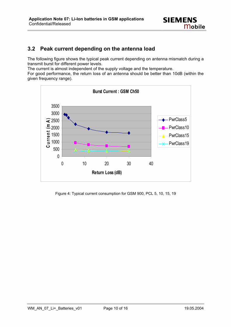
3.2 Peak current depending on the antenna load
The following figure shows the typical peak current depending on antenna mismatch during a transmit burst for different power levels. The current is almost independent of the supply voltage and the temperature. For good performance, the return loss of an antenna should be better than 10dB (within the given frequency range).
Figure 4: Typical current consumption for GSM 900, PCL 5, 10, 15, 19
Burst Current : GSM Ch50
0500
100015002000250030003500
0 10 20 30 40
Return Loss (dB)
Curr
ent (
mA
) PwrClass5PwrClass10PwrClass15PwrClass19

Application Note 07: Li-Ion batteries in GSM applications Confidential/Released s
mo b i l e
WM_AN_07_Li+_Batteries_v01 Page 11 of 16 19.05.2004
4 Typical properties of Li+ Batteries and its effects The most important feature when using batteries in a mobile application such as cellular telephones or PDAs, is the available capacity per volume. Chapter 3.1 and 3.2 describe battery properties and other influences, which lower the available capacity. The overall power supply resistance and the temperature have the biggest influence on the available capacity.
4.1 Effects of the application power supply resistance
A typical power supply resistance of a mobile application consists of: Table 4: Typical resistance of a power supply line
Cell resistance 10...40mΩ
Resistance of batteries protection circuit
80...100mΩ Battery
Resistance of pcb and connectors 20...100mΩ (depends on design) Application
Minimum overall resistance >110mΩ A current transmit burst of 2A results in a voltage drop of 0.22V in the power line. The undervoltage shut down threshold of a Siemens GSM module is 3.2V. It means that the battery is empty at 3.42V (only considering the internal resistance). Figure 5 illustrates a measurement under real conditions. It has been made during idle discharging with a current consumption of 10mA. Every hour a GSM call was established with PCL5 lasting one minute with a current profile 2A / 200mA, until the battery was discharged.
2 ,8
3
3 ,2
3 ,4
3 ,6
3 ,8
4
4 ,2
0 5 0 0 1 0 0 0 1 5 0 0 2 0 0 0 2 5 0 0 3 0 0 0
T im e [m in ]
Vbat
Figure 5:Voltage of a typical 1000mAh Li+ battery under discharge at 20°C
Application Note 07: Li-Ion batteries in GSM applications Confidential/Released s
mo b i l e
WM_AN_07_Li+_Batteries_v01 Page 12 of 16 19.05.2004
In addition to voltage drops caused by inner resistance there is the effect of recovery voltage (see Chapter 4.2). Both together result in a voltage recursion. Note that the voltage recursion increases with lower battery voltage. The values of the measured battery are as follows: Table 5: Measured resistance and voltage drops of a typical 1000mAh battery
Inner resistance @ 4.2V / 3.6V 90mΩ / 100mΩ (to multiply by 2A)
Recovery voltage @ 4.2V / 3.6V 80mV / 210mV
Voltage recursion @ 4.2V / 3.6V 260mV / 410mV In Figure 5 you can see the voltage recursion of 260 / 470mV as a sum of voltage drops caused by inner resistance and the recovery voltage. This means: At a voltage of 3.6V the battery is empty, because during a 1min call with PCL5 the battery voltage falls bellow 3.2V (module shuts off voltage). Note that at 3.6V a typical battery has only about 5% capacity left – the voltage is falling rapidly as well under idle load (10mA). Summary: The available capacity is depends on the recovery voltage and the power supply resistance. Design engineers should choose a battery with a low recovery voltage and a low inner resistance. Also the PCB power supply lines must be designed with low resistance.
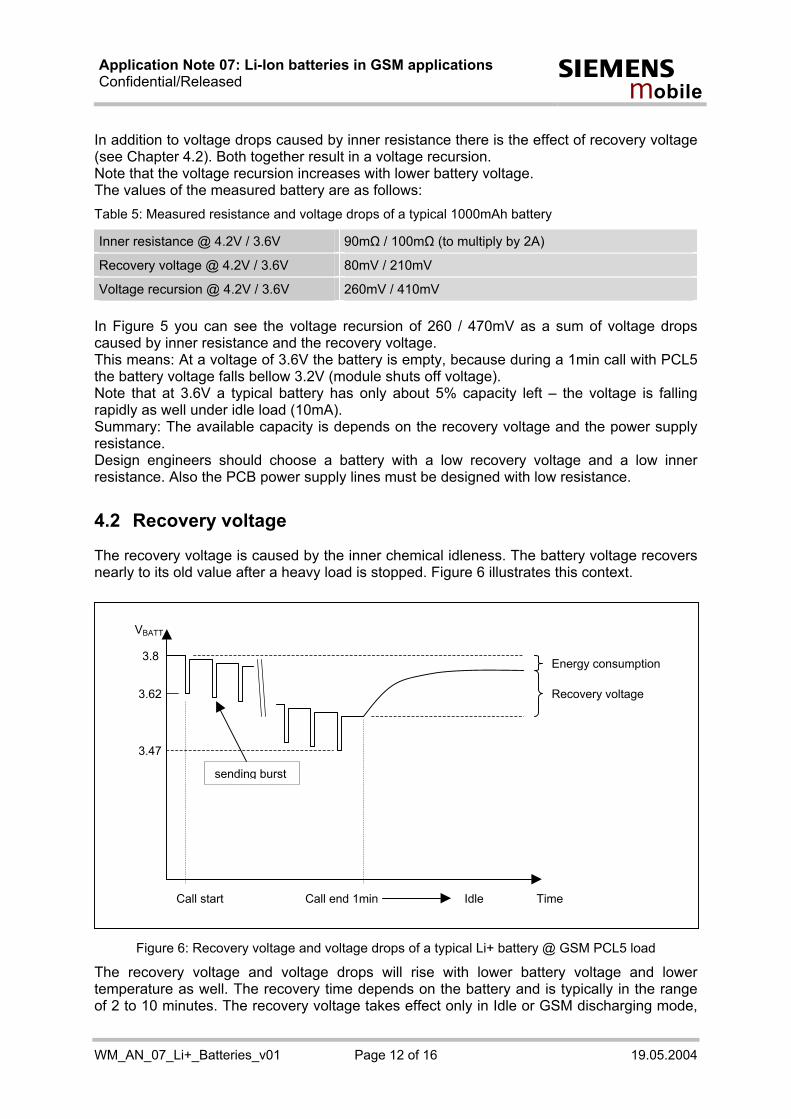
4.2 Recovery voltage
The recovery voltage is caused by the inner chemical idleness. The battery voltage recovers nearly to its old value after a heavy load is stopped. Figure 6 illustrates this context.
Figure 6: Recovery voltage and voltage drops of a typical Li+ battery @ GSM PCL5 load
The recovery voltage and voltage drops will rise with lower battery voltage and lower temperature as well. The recovery time depends on the battery and is typically in the range of 2 to 10 minutes. The recovery voltage takes effect only in Idle or GSM discharging mode,
3.8
3.62 Recovery voltage
Energy consumption
Call start
3.47
sending burst
Call end 1min Idle Time
VBATT
Application Note 07: Li-Ion batteries in GSM applications Confidential/Released s
mo b i l e
WM_AN_07_Li+_Batteries_v01 Page 13 of 16 19.05.2004
which is the normal state of a mobile equipment. If the battery is discharged only by GSM load, the recovery voltage has no effect, because the battery has no time for recovering. The implemented software and battery parameters in the Siemens GSM module consider these effects to achieve best results. In Idle state the module software calculates the voltage loss (inner resistance and recovery voltage) that will happen when a call is started. During idle mode, when the battery voltage is too low to guarantee a trouble free active call, the module shuts down. The intention is to guarantee enough remaining power for at least a 1 minute call (e.g. emergency call).
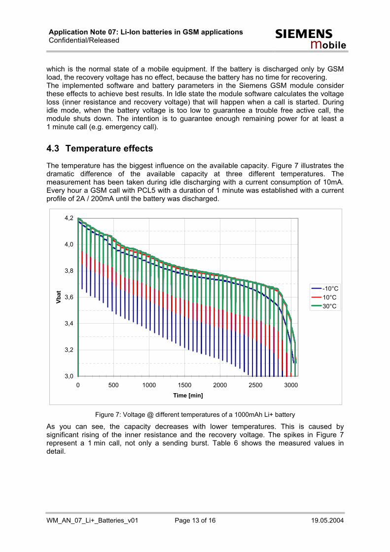
4.3 Temperature effects
The temperature has the biggest influence on the available capacity. Figure 7 illustrates the dramatic difference of the available capacity at three different temperatures. The measurement has been taken during idle discharging with a current consumption of 10mA. Every hour a GSM call with PCL5 with a duration of 1 minute was established with a current profile of 2A / 200mA until the battery was discharged.
Figure 7: Voltage @ different temperatures of a 1000mAh Li+ battery
As you can see, the capacity decreases with lower temperatures. This is caused by significant rising of the inner resistance and the recovery voltage. The spikes in Figure 7 represent a 1 min call, not only a sending burst. Table 6 shows the measured values in detail.
3,0
3,2
3,4
3,6
3,8
4,0
4,2
0 500 1000 1500 2000 2500 3000
Time [min]
Vbat
-10°C10°C30°C

Application Note 07: Li-Ion batteries in GSM applications Confidential/Released s
mo b i l e
WM_AN_07_Li+_Batteries_v01 Page 14 of 16 19.05.2004
Table 6: Measured battery under temperature influence
Temperature Relative capacity Internal resistance Recovery voltage
-10°C 54% 115mΩ 490mV
10°C 92% 95mΩ 330mV
30°C 100% 85mΩ 140mV For use of the mobile equipment at lower temperatures, design engineers should choose a battery with the lowest recovery voltage to get more capacity. Even a battery with a lower nominal capacity and low recovery voltage may be much more suitable than a battery with higher nominal capacity and higher recovery voltage. These effects have also been considered by the implemented software and battery parameters in the Siemens GSM module.
5 Construction advices
5.1 Reduced resistance between battery and module
Generally, the power lines of the FF cable or PCB tracks connecting the module with the battery, should be as short and low resistant as possible. To minimize the effect of voltage drops (max. 400mV recommended), you can decrease the GND resistance by using additional ground connections from the module to the customer application. This can be done by using a screw or spring contact and as well via soldering on the battery contact pads (not for all GSM engines). Typical resistance values are listed in the table below. These values increase up to 80% when decreasing the temperature to –10°C! Table 7: Typical values of a battery application at 2A current burst
Voltage recursion at the module Measured resistance at 25°C
ZIF B2B
Battery and protection circuitry ≈100 mΩ 200mV 200mV
Battery spring connections 2 x 6 mΩ 24mV 24mV
PCB and ZIF/B2B connector 2 x 9 mΩ 36mV 36mV
Short FFC 2 x 8 mΩ 32mV -
ZIF connector 2 x 7 mΩ 28mV -
Sum 320mV 260mV

Application Note 07: Li-Ion batteries in GSM applications Confidential/Released s
mo b i l e
WM_AN_07_Li+_Batteries_v01 Page 15 of 16 19.05.2004
6 Implemented charging technique The implemented charging technique consists of trickle charging and processor controlled fast and final charging. For this solution, the fast charging current provided by the charger or any other external source must be limited to 500mA. For detailed requirements on the charging circuit please refer to [1].
After trickle charging has raised the battery voltage to 3.2V, within 60 minutes after connecting the charger fast charging begins. If the battery voltage was already above 3.2V, processor controlled fast charging starts after the charger was connected to the POWER pins. Fast charging delivers a constant current until the battery voltage reaches 4.2V.
• If the overall current consumption of module and application is more than 200mA (set the current consumption of your application with the AT command “AT^SBC=xxx”), fast charging ends at this point. This prevents the battery voltage from overshooting beyond 4.2V in case of deactivated load. E.g. when charging up to nearly 4.2V when a call is in progress, this may terminate the call, because the battery voltage may overshoot 4.2 or 4.3V caused by charging current – battery’s protection circuit may disconnect the battery cell.
• If the overall current consumption of module and application is less than 200mA (set the current consumption of your application with the AT command “AT^SBC=xxx”), final charging begins with changing pulse duty cycle. As shown in Figure 8, the pulse duty cycle is reduced to adjust the charging current. The average duty cycle charging current goes down to 5% of the available fast charge current (500mA maximum). Once the pulse width reaches the minimum of 100ms and the duty cycle does not change for 2 minutes, fast charging is completed. This reduction of the pulse duty cycle is similar to a constant voltage source.
If the charger is connected permanently, the charging process starts again after the end of charging, when the battery voltage falls below 4.0V (approximately). The difference in capacity for these two charging methods depends on the battery and is in the range of 5 to 10%. For best charging results you need to set the current consumption of your application.
4.3
4.2
3.8
Voltage
3.4
3.0
Constant current tOFF = 100 ms tON = 100 ms Time
100ms 2 ... 0.1s 100ms 0.1 ... 2s
End of charging
Figure 8: Charging process (quality representation)

Application Note 07: Li-Ion batteries in GSM applications Confidential/Released s
mo b i l e
WM_AN_07_Li+_Batteries_v01 Page 16 of 16 19.05.2004
Note: The battery manufacturer must guarantee that the battery complies with the described charging technique.
7 Siemens support for battery parameterization Siemens WM AE offers support for battery qualification, measurements and judgment. To adjust any battery to your application, Siemens prepares individual parameter sets for your Siemens GSM module, so the battery is best adjusted to your application.