applications for the abi mobilram-system tm 14/17 pile
TRANSCRIPT
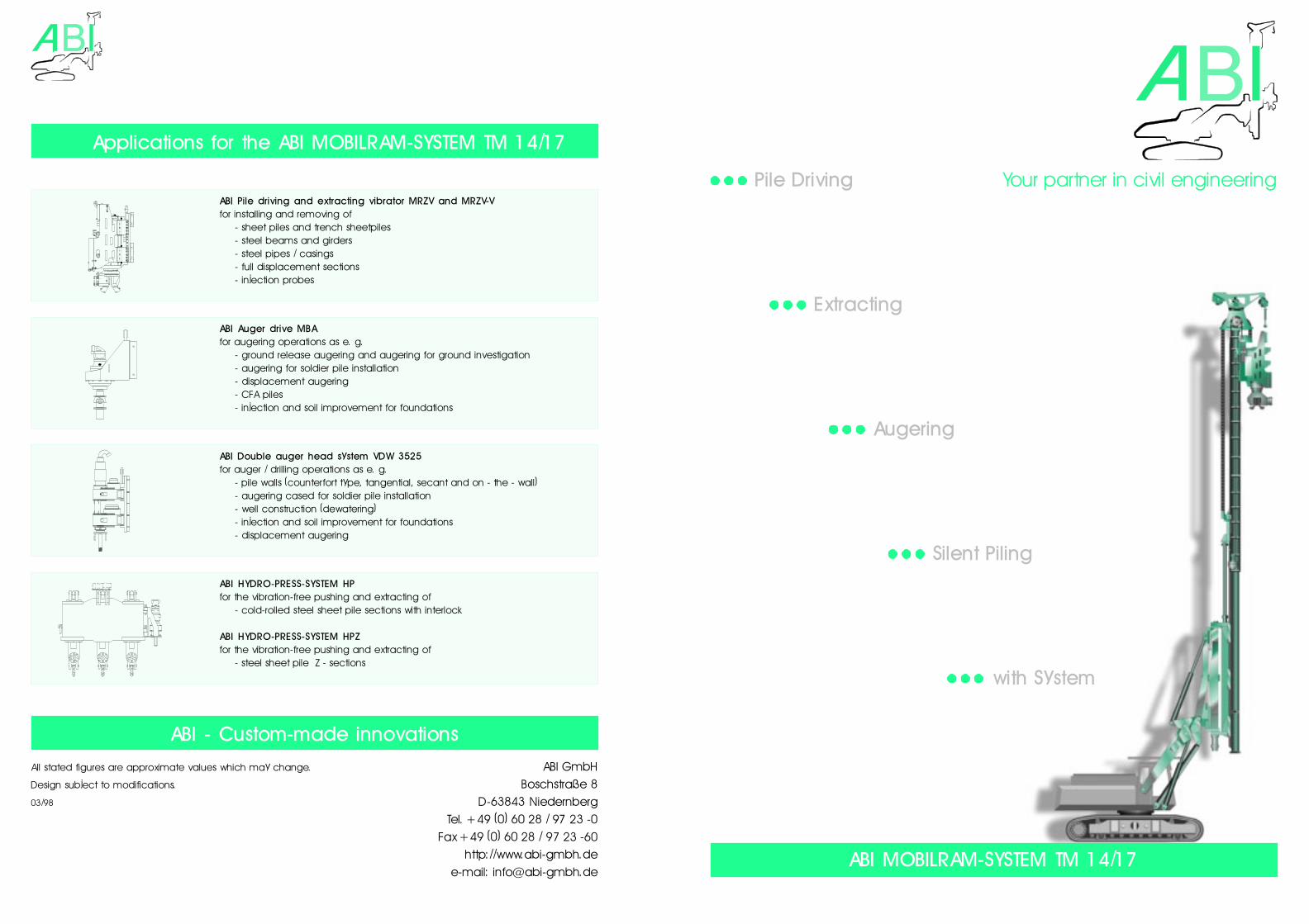
ABI MOBILRAM-SYSTEM TM 14/17
Your partner in civil engineering
ABI GmbHBoschstraße 8
D-63843 NiedernbergTel. +49 (0) 60 28 / 97 23 -0
Fax +49 (0) 60 28 / 97 23 -60http://www.abi-gmbh.de
e-mail: [email protected]
Applications for the ABI MOBILRAM-SYSTEM TM 14/17
ABI - Custom-made innovations
All stated figures are approximate values which may change.
Design subject to modifications.
03/98
ABI HYDRO-PRESS-SYSTEM HPfor the vibration-free pushing and extracting of
- cold-rolled steel sheet pile sections with interlock
ABI HYDRO-PRESS-SYSTEM HPZfor the vibration-free pushing and extracting of
- steel sheet pile Z - sections
ABI Double auger head system VDW 3525for auger / drilling operations as e. g.
- pile walls (counterfort type, tangential, secant and on - the - wall)- augering cased for soldier pile installation- well construction (dewatering)- injection and soil improvement for foundations- displacement augering
ABI Pile driving and extracting vibrator MRZV and MRZV-Vfor installing and removing of
- sheet piles and trench sheetpiles- steel beams and girders- steel pipes / casings- full displacement sections- injection probes
ABI Auger drive MBAfor augering operations as e. g.
- ground release augering and augering for ground investigation- augering for soldier pile installation- displacement augering- CFA piles- injection and soil improvement for foundations
Pile Driving
Extracting
Augering
Silent Piling
with System
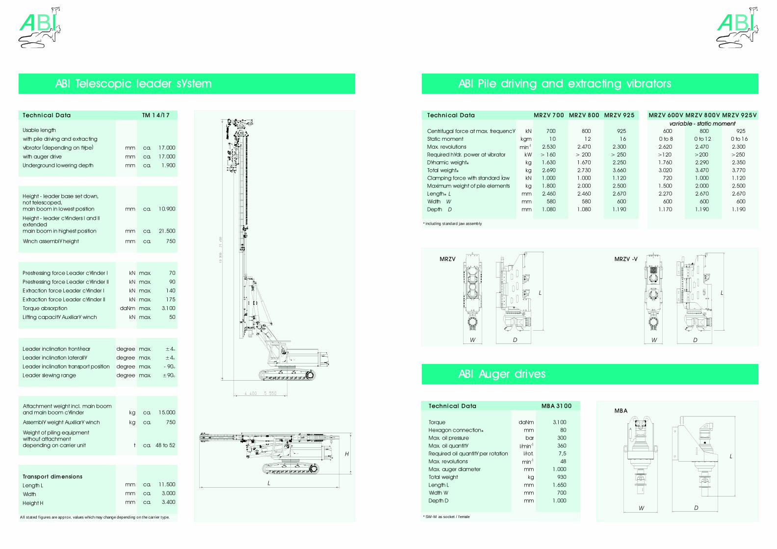
Technical Data TM 14/17
Usable length
with pile driving and extracting
vibrator (depending on type) mm ca. 17.000
with auger drive mm ca. 17.000
Underground lowering depth mm ca. 1.900
Height - leader base set down,not telescoped,main boom in lowest position mm ca. 10.900
Height - leader cylinders I and IIextendedmain boom in highest position mm ca. 21.500
Winch assembly height mm ca. 750
Prestressing force Leader cylinder I kN max. 70
Prestressing force Leader cylinder II kN max. 90
Extraction force Leader cylinder I kN max. 140
Extraction force Leader cylinder II kN max. 175
Torque absorption daNm max. 3.100
Lifting capacity Auxiliary winch kN max. 50
Leader inclination front/rear degree max. ±4°
Leader inclination laterally degree max. ±4°
Leader inclination transport position degree max. - 90°
Leader slewing range degree max. ±90°
Attachment weight incl. main boomand main boom cylinder kg ca. 15.000
Assembly weight Auxiliary winch kg ca. 750
Weight of piling equipmentwithout attachmentdepending on carrier unit t ca. 48 to 52
Transpo rt dimensions
Length L mm ca. 11.500
Width mm ca. 3.000
Height H mm ca. 3.400
All stated f igures are approx. values which may change depending on the carrier type.
Technical Data MBA 3100
Torque daNm 3.100 Hexagon connection* mm 80 Max. oil pressure bar 300 Max. oil quantity l/min-1 360 Required oil quantity per rotation l/rot. 7,5 Max. revolutions min-1 48 Max. auger diameter mm 1.000 Total weight kg 930 Length L mm 1.650 Width W mm 700 Depth D mm 1.000
* SW-M as socket / female
Technical Data MRZV 700 MRZV 800 MRZV 925 MRZV 600V MRZV 800V MRZV 925Vvariable - static moment
Centrifugal force at max. frequency kN 700 800 925 600 800 925 Static moment kgm 10 12 16 0 to 8 0 to 12 0 to 16Max. revolutions min-1 2.530 2.470 2.300 2.620 2.470 2.300 Required hydr. power at vibrator kW > 160 > 200 > 250 >120 >200 >250 Dynamic weight* kg 1.630 1.670 2.250 1.760 2.290 2.350 Total weight* kg 2.690 2.730 3.660 3.020 3.470 3.770 Clamping force with standard jaw kN 1.000 1.000 1.120 720 1.000 1.120 Maximum weight of pile elements kg 1.800 2.000 2.500 1.500 2.000 2.500 Length* L mm 2.460 2.460 2.670 2.270 2.670 2.670 Width W mm 580 580 600 600 600 600 Depth D mm 1.080 1.080 1.190 1.170 1.190 1.190
* including standard jaw assembly
H
L
ABI Telescopic leader system
W WD D
L L
W D
L
MRZV MRZV -V
MBA
ABI Pile driving and extracting vibrators
ABI Auger drives