application note – performance ... application note – performance characteristics of the xrt7300...
TRANSCRIPT

TAN-030 Application Note – Performance Characteristics of the XRT7300 Device for DS3 Applications Rev. 1.00
1
APPLICATION NOTE – PERFORMANCE CHARACTERISTICS OF THE XRT7300 DEVICE FOR DS3
APPLICATIONS

TAN-030 Application Note – Performance Characteristics of the XRT7300 Device for DS3 Applications Rev. 1.00
2
Table of Contents Table of Contents........................................................................................................................................... 2 1.0 INTRODUCTION .................................................................................................................................. 3 2.0 TRANSMIT OUTPUT PULSE TEMPLATE MEASUREMENTS – DS3 APPLICATIONS ............. 3
2.1 THE TRANSMIT OUTPUT PULSE TEMPLATE TEST/MEASUREMENT RESULTS...... 3 2.2 THE TRANSMIT OUTPUT PULSE TEMPLATE TEST/MEASUREMENT APPROACH ......... 9 How the Test Set up works ..................................................................................................................... 10
2.2.1 Testing with 2 feet of Cable Loss .............................................................................................. 11 2.2.2 Testing with 225 feet of Cable Loss ......................................................................................... 11 2.2.3 Testing with 450 feet of Cable Loss ......................................................................................... 13
3.0 RECEIVE SENSITIVITY OF THE XRT7300 DEVICE FOR DS3 AND STS-1 APPLICATIONS. ........................................................................................................................................ 14
3.1 THE RECEIVE SENSITIVITY TEST/MEASUREMENT RESULTS ......................................... 14 3.2 RECEIVE SENSITIVITY TEST/MEASUREMENT APPROACH .............................................. 16
3.2.1 Pure Cable-Loss from the DSX-3/STSX-1 Cross-Connect Location ...................................... 17 3.2.2 Flat Loss, over and above “DSX-3/STSX-1 Cross-Connect Location” plus 450 of cable loss............................................................................................................................................................. 19 3.2.3 Pure Flat Loss from the “DSX-3/STSX-1 Cross-Connect” Location. ................................... 20
4.0 THE INPUT JITTER TOLERANCE CAPABILITY OF THE XRT7300 DEVICE, FOR DS3 APPLICATIONS. ........................................................................................................................................ 22
4.1 THE INPUT JITTER TOLERANCE TEST RESULTS FOR THE XRT7300 DEVICE. ............ 22 4.2 THE JITTER TOLERANCE MEASUREMENT TEST PROCEDURE....................................... 25
TAN-030 Application Note – Performance Characteristics of the XRT7300 Device for DS3 Applications Rev. 1.00
3
1.0 INTRODUCTION The purpose of this Applications Note is to document some of the Performance Characteristics of the XRT7300 Device, for DS3 Applications. In particular, this Application Note will document the following. • The Transmit Output Pulse of the XRT7300 Device, and how well it complies with “Isolated Transmit Output Pulse Template” requirements for DS3 applications (per Bellcore GR-499-CORE, and ANSI TI.102)”. • The Receive Sensitivity of the XRT7300 Device. • The Input Jitter Tolerance Capability of the XRT7300 Device, for DS3 Applications, and how well it complies to the “Input Jitter Tolerance Requirements”, (per Bellcore GR-499-CORE). NOTE: In each of these parameters, this Application Note will address two (2) things.
a. The Test Results, and b. The Test Procedure/Approach that we used to obtain these results.
2.0 TRANSMIT OUTPUT PULSE TEMPLATE MEASUREMENTS – DS3 APPLICATIONS This section will discuss the following two (2) topics in some detail. a. The Test/Measurement Results when testing to verify that the Transmit Output (of the XRT7300 device) complies with the Isolated Pulse Template requirements (per Bellcore GR-499-CORE and ANSI TI.102). b. The Test/Measurement Approach for Verifying that the Transmit Output of the XRT7300 device complies with these pulse template requirements. 2.1 THE TRANSMIT OUTPUT PULSE TEMPLATE
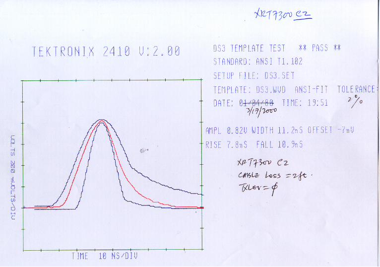
TEST/MEASUREMENT RESULTS Included with this Application Note are four (4) plots. A brief description of each of these plots are presented below. PLOT 1 (In Figure 1 of this document) – The XRT7300 Transmit Output pulse (plotted against the ANSI TI.102 DS3 pulse template requirement curves) after being subjected to 2 feet of cable-loss (Transmit Line Build-Out Circuit = ON).
TAN-030 Application Note – Performance Characteristics of the XRT7300 Device for DS3 Applications Rev. 1.00
4
PLOT 2 (In Figure 2 of this document) – The XRT7300 Transmit Output pulse (plotted against the ANSI TI.102 DS3 pulse template requirement curves) after being subjected to 225 feet of cable-loss (Transmit Line Build-Out Circuit = ON). PLOT 3 (In Figure 3 of this document) – The XRT7300 Transmit Output pulse (plotted against the ANSI TI.102 DS3 pulse template requirement curves) after being subjected to 225 feet of cable-loss (Transmit Line Build-Out Circuit = OFF). PLOT 4 (In Figure 4 of this document) – The XRT7300 Transmit Output pulse (plotted against the ANSI TI.102 DS3 pulse template requirement curves) after being subjected to 450 feet of cable-loss (Transmit Line Build-Out Circuit = OFF). In each of these plots the “Transmit Output” pulse (of the XRT7300 device) is overlayed on top of the “ANSI TI.102 Pulse Template Requirements. In each of these cases, the “Transmit Output Pulse” is said to be “passing” the “Pulse Template” requirements, if the “Transmit Output Pulse” curve (as captured via the “Tektronics Oscilloscope) is NOT touching the either the lower or upper curves of the “Pulse Template” requirements.

TAN-030 Application Note – Performance Characteristics of the XRT7300 Device for DS3 Applications Rev. 1.00
5
PLOT 1 (In Figure 1 of this document) – The XRT7300 Transmit Output pulse (plotted against the ANSI TI.102 DS3 pulse template requirement curves) after being subjected to 2 feet of cable-loss (Transmit Line Build-Out Circuit = ON).
TAN-030 Application Note – Performance Characteristics of the XRT7300 Device for DS3 Applications Rev. 1.00
6
PLOT 2 (In Figure 2 of this document) – The XRT7300 Transmit Output pulse (plotted against the ANSI TI.102 DS3 pulse template requirement curves) after
being subjected to 225 feet of cable-loss (Transmit Line Build-Out Circuit = ON).

TAN-030 Application Note – Performance Characteristics of the XRT7300 Device for DS3 Applications Rev. 1.00
7
PLOT 3 (In Figure 3 of this document) – The XRT7300 Transmit Output pulse (plotted against the ANSI TI.102 DS3 pulse template requirement curves) after
being subjected to 225 feet of cable-loss (Transmit Line Build-Out Circuit = OFF).


TAN-030 Application Note – Performance Characteristics of the XRT7300 Device for DS3 Applications Rev. 1.00
8
PLOT 4 (In Figure 4 of this document) – The XRT7300 Transmit Output pulse (plotted against the ANSI TI.102 DS3 pulse template requirement curves) after
being subjected to 450 feet of cable-loss (Transmit Line Build-Out Circuit = OFF).

TAN-030 Application Note – Performance Characteristics of the XRT7300 Device for DS3 Applications Rev. 1.00
9
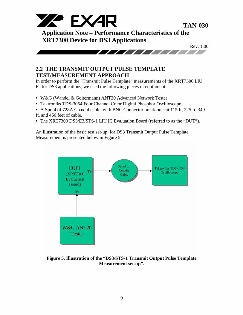
2.2 THE TRANSMIT OUTPUT PULSE TEMPLATE TEST/MEASUREMENT APPROACH In order to perform the “Transmit Pulse Template” measurements of the XRT7300 LIU IC for DS3 applications, we used the following pieces of equipment. • W&G (Wandel & Goltermann) ANT20 Advanced Network Tester • Tektroniks TDS-3054 Four Channel Color Digital Phosphor Oscilloscope. • A Spool of 728A Coaxial cable, with BNC Connector break-outs at 115 ft, 225 ft, 340 ft, and 450 feet of cable. • The XRT7300 DS3/E3/STS-1 LIU IC Evaluation Board (referred to as the “DUT”). An illustration of the basic test set-up, for DS3 Transmit Output Pulse Template Measurement is presented below in Figure 5.
DUT(XRT7300Evaluation
Board)
DUT(XRT7300Evaluation
Board)
Spool of CoaxialCable
Spool of CoaxialCable
Tektroniks TDS-3054Oscilloscope
Tektroniks TDS-3054Oscilloscope
W&G ANT20Tester
W&G ANT20Tester
Rx
Tx
Figure 5, Illustration of the “DS3/STS-1 Transmit Output Pulse Template
Measurement set-up”.

TAN-030 Application Note – Performance Characteristics of the XRT7300 Device for DS3 Applications Rev. 1.00
10
Figure 5 indicates the following. 1. That the “Transmit Output” of the “W&G ANT20 Tester” is connected to the Receive Input of the XRT7300 Evaluation Board (or the DUT). 2. That the “Transmit Output” of the XRT7300 Evaluation Board (or the DUT) is
connected to either the “Spool of Coaxial cable” or directly to the Receive Input of the “Tektroniks TDS-3054 Oscilloscope
Things which are not obvious within Figure 5. 1. The Transmit Output of the W&G ANT20 Tester is set to “DSX-3”. 2. The W&G ANT20 Tester was configured to transmit a DS3 line signal carrying a repeating “100” pattern. 3. The XRT7300 Evaluation Board (e.g., the DUT) was configured to operate in the
“Remote Loop-back” Mode. 4. The “Tektroniks TDS-3054 Oscilloscope” contains a “Bellcore/ANSI Pulse Template
Overlay” which can be superimposed on the display of the Oscilloscope. This feature makes it easy for a user to determine whether the transmit output (from the XRT7300 device) complies with the “Pulse-Template” or not.
How the Test Set up works The W&G ANT20 Tester is configured to transmit a DS3 line signal, that contains a repeating “100” pattern. This particular pattern was selected because it is recommended (per Bellcore GR-499-CORE) for use when verifying “Pulse Template Requirement” measurements. The XRT7300 LIU IC (which resides within the DUT) receives this DS3 line signal (from the W&G ANT20) and does the following. • The Receive Section of the LIU IC performs “Clock” and “Data Recovery” of the DS3 line signal (from the W&G ANT20). • Since the XRT7300 LIU device is configured to operate in the “Remote Loop-back” Mode; then it will take the recovered data and clock, and will use it to generate (and transmit) a DS3 line signal to the “Tektroniks Oscilloscope”. As this DS3 line signal is routed to the “Tektroniks Oscilloscope”, it will be subjected to a certain amount of “cable-loss”, as described below. Next, we proceeded measure the “Transmit Output” pulse of the XRT7300 device and compare it with the “Isolated Pulse Template” requirements per ANSI TI.102. These measurements were performed with the following amounts of cable loss inserted between the W&G ANT20 and the DUT.

TAN-030 Application Note – Performance Characteristics of the XRT7300 Device for DS3 Applications Rev. 1.00
11
• 2 feet of Cable Loss • 225 feet of Cable Loss • 450 feet of Cable Loss. A brief description of the test procedure that was used with each of these amounts of cable loss, is presented below.
2.2.1 Testing with 2 feet of Cable Loss When we tested and verified that the “Transmit Output Pulse” (of the XRT7300 device) complies with the “DS3 Isolated Pulse Template requirements (per ANSI TI.102), with 2 feet of cable loss, we did the following. • We directly connected the Transmit Output of the “DUT” (Device Under Test) to the “Tektroniks Oscilloscope (by-passing the “Spool of Coaxial Cable”). • We then enabled the “Transmit Line Build-Out” circuit (within the XRT7300 device), by setting the “TxLEV” input pin to “GND”. By doing this, the XRT7300 device (via the “Transmit Line Build-Out” circuit) will shape the “Transmit Output” pulses to comply with the “Pulse Template” requirements over “short-cable” lengths. • We then captured and plotted the waveform of the Transmit Output pulse (from the XRT7300 device) via the Tektroniks Oscilloscope. The Transmit Output pulse, when superimposed over the “ANSI TI.102” pulse template requirement curves (for DS3 applications) is presented in Figure 1. This plot indicates that the “Transmit Output” pulse (of the XRT7300 device) complies with the DS3 pulse template requirements (per ANSI TI.102) when subjected to 2 feet of cable loss. NOTE: The “2 feet” of cable loss was realized via the strand of coaxial cable which was connected between the “Transmit Output” of the DUT and the “Receive Input” of the Tektroniks” Oscilloscope.
2.2.2 Testing with 225 feet of Cable Loss When we tested and verified that the “Transmit Output Pulse” (of the XRT7300 device) complies with the “DS3 Isolated Pulse Template requirements (per ANSI TI.102), with 225 feet of cable loss, we did the following. • We connected the Transmit Output of the “DUT” to the “Spool of Coaxial Cable”.
TAN-030 Application Note – Performance Characteristics of the XRT7300 Device for DS3 Applications Rev. 1.00
12
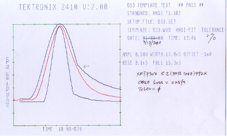
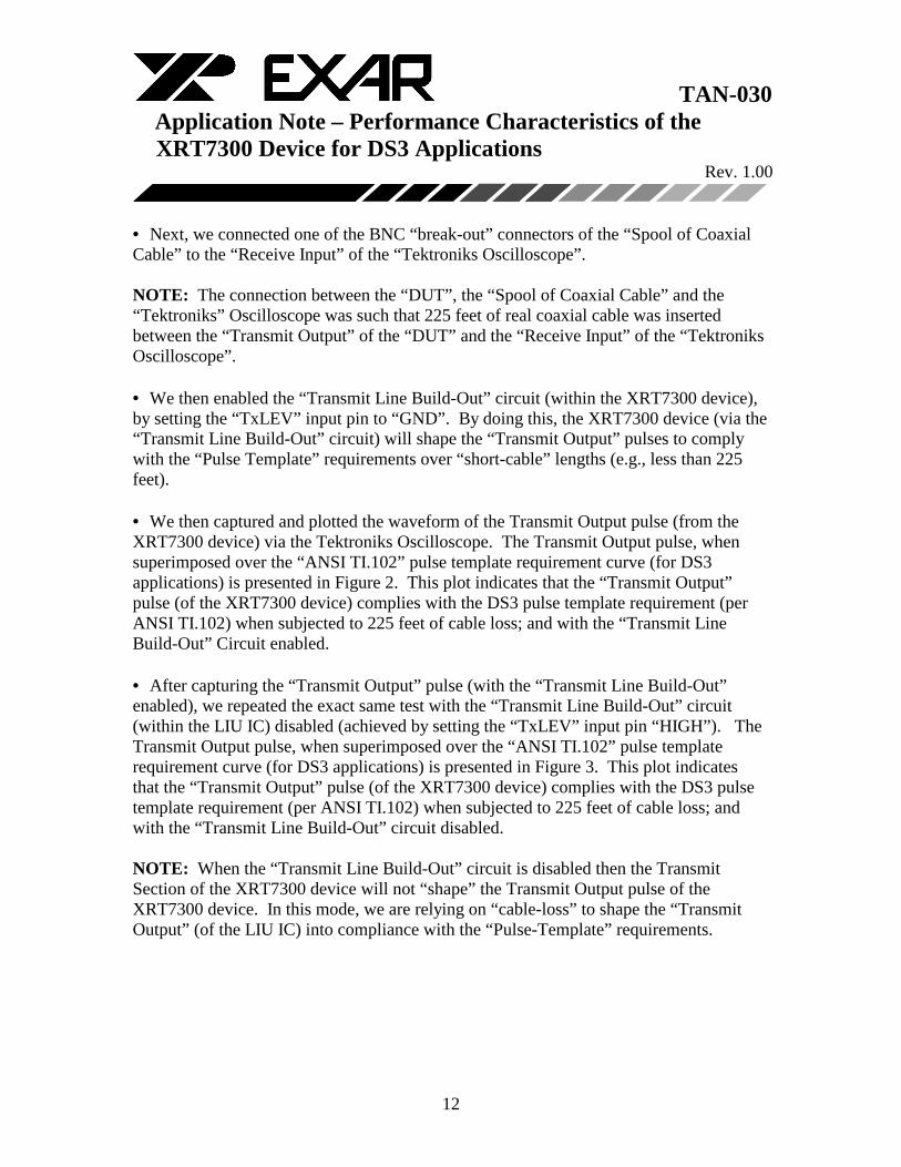
• Next, we connected one of the BNC “break-out” connectors of the “Spool of Coaxial Cable” to the “Receive Input” of the “Tektroniks Oscilloscope”. NOTE: The connection between the “DUT”, the “Spool of Coaxial Cable” and the “Tektroniks” Oscilloscope was such that 225 feet of real coaxial cable was inserted between the “Transmit Output” of the “DUT” and the “Receive Input” of the “Tektroniks Oscilloscope”. • We then enabled the “Transmit Line Build-Out” circuit (within the XRT7300 device), by setting the “TxLEV” input pin to “GND”. By doing this, the XRT7300 device (via the “Transmit Line Build-Out” circuit) will shape the “Transmit Output” pulses to comply with the “Pulse Template” requirements over “short-cable” lengths (e.g., less than 225 feet). • We then captured and plotted the waveform of the Transmit Output pulse (from the XRT7300 device) via the Tektroniks Oscilloscope. The Transmit Output pulse, when superimposed over the “ANSI TI.102” pulse template requirement curve (for DS3 applications) is presented in Figure 2. This plot indicates that the “Transmit Output” pulse (of the XRT7300 device) complies with the DS3 pulse template requirement (per ANSI TI.102) when subjected to 225 feet of cable loss; and with the “Transmit Line Build-Out” Circuit enabled. • After capturing the “Transmit Output” pulse (with the “Transmit Line Build-Out” enabled), we repeated the exact same test with the “Transmit Line Build-Out” circuit (within the LIU IC) disabled (achieved by setting the “TxLEV” input pin “HIGH”). The Transmit Output pulse, when superimposed over the “ANSI TI.102” pulse template requirement curve (for DS3 applications) is presented in Figure 3. This plot indicates that the “Transmit Output” pulse (of the XRT7300 device) complies with the DS3 pulse template requirement (per ANSI TI.102) when subjected to 225 feet of cable loss; and with the “Transmit Line Build-Out” circuit disabled. NOTE: When the “Transmit Line Build-Out” circuit is disabled then the Transmit Section of the XRT7300 device will not “shape” the Transmit Output pulse of the XRT7300 device. In this mode, we are relying on “cable-loss” to shape the “Transmit Output” (of the LIU IC) into compliance with the “Pulse-Template” requirements.
TAN-030 Application Note – Performance Characteristics of the XRT7300 Device for DS3 Applications Rev. 1.00
13
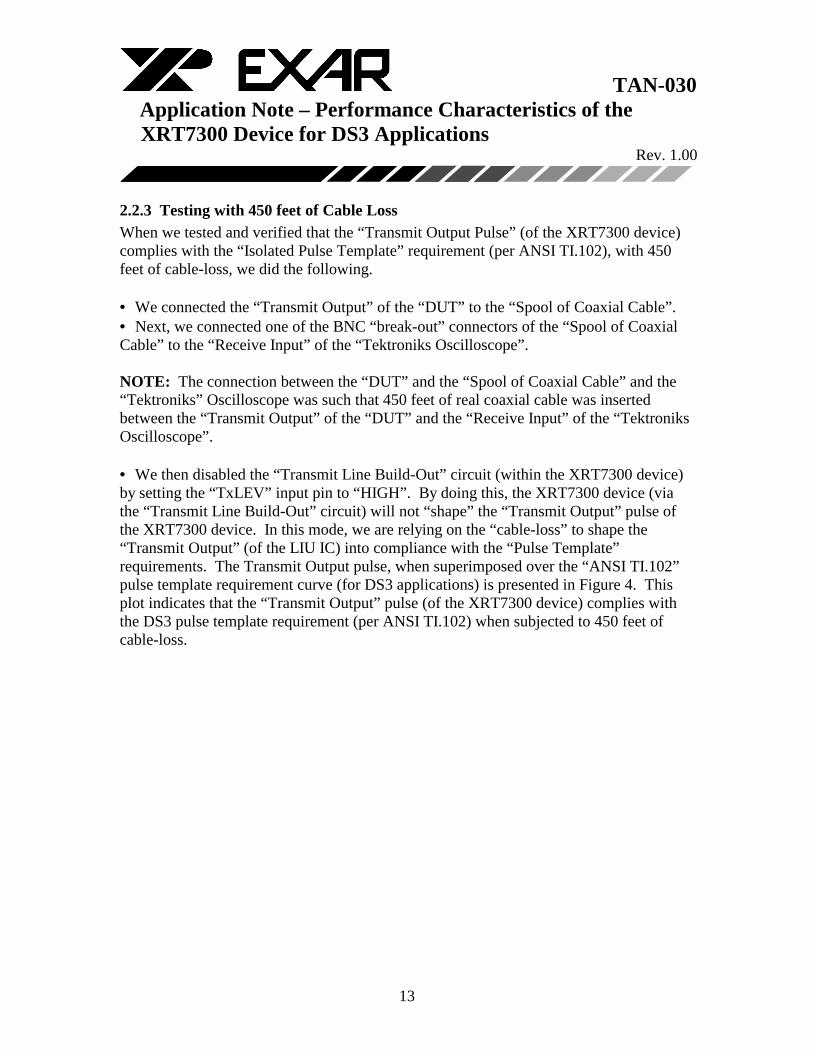
2.2.3 Testing with 450 feet of Cable Loss When we tested and verified that the “Transmit Output Pulse” (of the XRT7300 device) complies with the “Isolated Pulse Template” requirement (per ANSI TI.102), with 450 feet of cable-loss, we did the following. • We connected the “Transmit Output” of the “DUT” to the “Spool of Coaxial Cable”. • Next, we connected one of the BNC “break-out” connectors of the “Spool of Coaxial Cable” to the “Receive Input” of the “Tektroniks Oscilloscope”. NOTE: The connection between the “DUT” and the “Spool of Coaxial Cable” and the “Tektroniks” Oscilloscope was such that 450 feet of real coaxial cable was inserted between the “Transmit Output” of the “DUT” and the “Receive Input” of the “Tektroniks Oscilloscope”. • We then disabled the “Transmit Line Build-Out” circuit (within the XRT7300 device) by setting the “TxLEV” input pin to “HIGH”. By doing this, the XRT7300 device (via the “Transmit Line Build-Out” circuit) will not “shape” the “Transmit Output” pulse of the XRT7300 device. In this mode, we are relying on the “cable-loss” to shape the “Transmit Output” (of the LIU IC) into compliance with the “Pulse Template” requirements. The Transmit Output pulse, when superimposed over the “ANSI TI.102” pulse template requirement curve (for DS3 applications) is presented in Figure 4. This plot indicates that the “Transmit Output” pulse (of the XRT7300 device) complies with the DS3 pulse template requirement (per ANSI TI.102) when subjected to 450 feet of cable-loss.
TAN-030 Application Note – Performance Characteristics of the XRT7300 Device for DS3 Applications Rev. 1.00
14
3.0 RECEIVE SENSITIVITY OF THE XRT7300 DEVICE FOR DS3
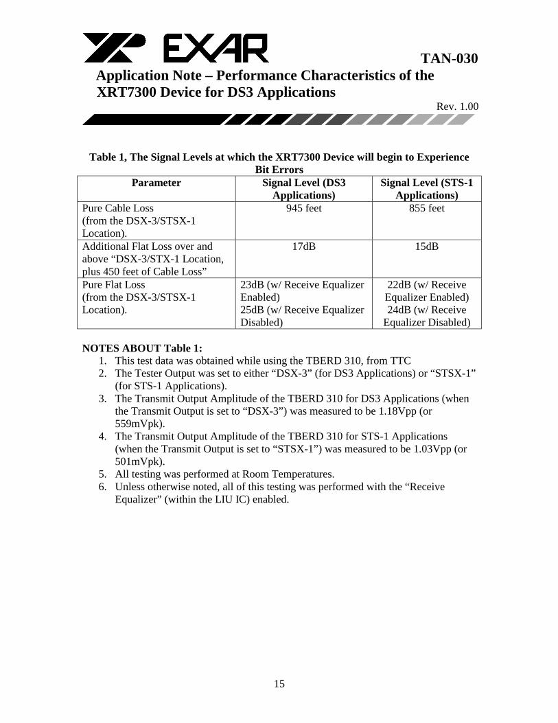
AND STS-1 APPLICATIONS. This section discusses the following topics in some detail. • The Receive Sensitivity measurements of the XRT7300 LIU IC for both DS3 and STS-1 applications. • The Test Procedure/Approach used to obtain these results. 3.1 THE RECEIVE SENSITIVITY TEST/MEASUREMENT RESULTS In this document, the “Receive Sensitivity” of the XRT7300 LIU IC is defined as the smallest amplitude signal that the LIU IC can receive in an “error-free” manner. The Receive Sensitivity of the LIU IC can be expressed in any of the following three terms. • Pure Cable Loss • Additional Flat Loss, over and above 450 feet of Cable Loss • Pure Flat Loss. Each of these three terms are defined below. Pure Cable Loss This is the maximum amount of cable loss (from the “DSX-3/STSX-1 Cross-Connect” location) that one can insert into the “Receive Path” before the XRT7300 device begins to experience bit errors. Additional Flat Loss, over and above 450 feet of Cable Loss This is the maximum amount of flat loss (over and above the mandated 450 feet of cable loss, from the “DSX-3/STSX-1 Cross-Connect” location) that one can insert into the “Receive Path” before the XRT7300 device will begin to experience bit-errors. Pure Flat Loss This is the maximum amount of flat loss (from the “DSX-3/STSX-1 Cross-Connect” location) that one can insert into the “Receive Path” before the XRT7300 device will begin to experience bit-errors. The signal levels (expressed in each of these three terms) that the XRT7300 device will begin to experience Bit Errors, is presented below in Table 1.
TAN-030 Application Note – Performance Characteristics of the XRT7300 Device for DS3 Applications Rev. 1.00
15
Table 1, The Signal Levels at which the XRT7300 Device will begin to Experience
Bit Errors Parameter Signal Level (DS3
Applications) Signal Level (STS-1
Applications) Pure Cable Loss (from the DSX-3/STSX-1 Location).
945 feet 855 feet
Additional Flat Loss over and above “DSX-3/STX-1 Location, plus 450 feet of Cable Loss”
17dB 15dB
Pure Flat Loss (from the DSX-3/STSX-1 Location).
23dB (w/ Receive Equalizer Enabled) 25dB (w/ Receive Equalizer Disabled)
22dB (w/ Receive Equalizer Enabled) 24dB (w/ Receive
Equalizer Disabled) NOTES ABOUT Table 1:
1. This test data was obtained while using the TBERD 310, from TTC 2. The Tester Output was set to either “DSX-3” (for DS3 Applications) or “STSX-1”
(for STS-1 Applications). 3. The Transmit Output Amplitude of the TBERD 310 for DS3 Applications (when
the Transmit Output is set to “DSX-3”) was measured to be 1.18Vpp (or 559mVpk).
4. The Transmit Output Amplitude of the TBERD 310 for STS-1 Applications (when the Transmit Output is set to “STSX-1”) was measured to be 1.03Vpp (or 501mVpk).
5. All testing was performed at Room Temperatures. 6. Unless otherwise noted, all of this testing was performed with the “Receive
Equalizer” (within the LIU IC) enabled.
TAN-030 Application Note – Performance Characteristics of the XRT7300 Device for DS3 Applications Rev. 1.00
16
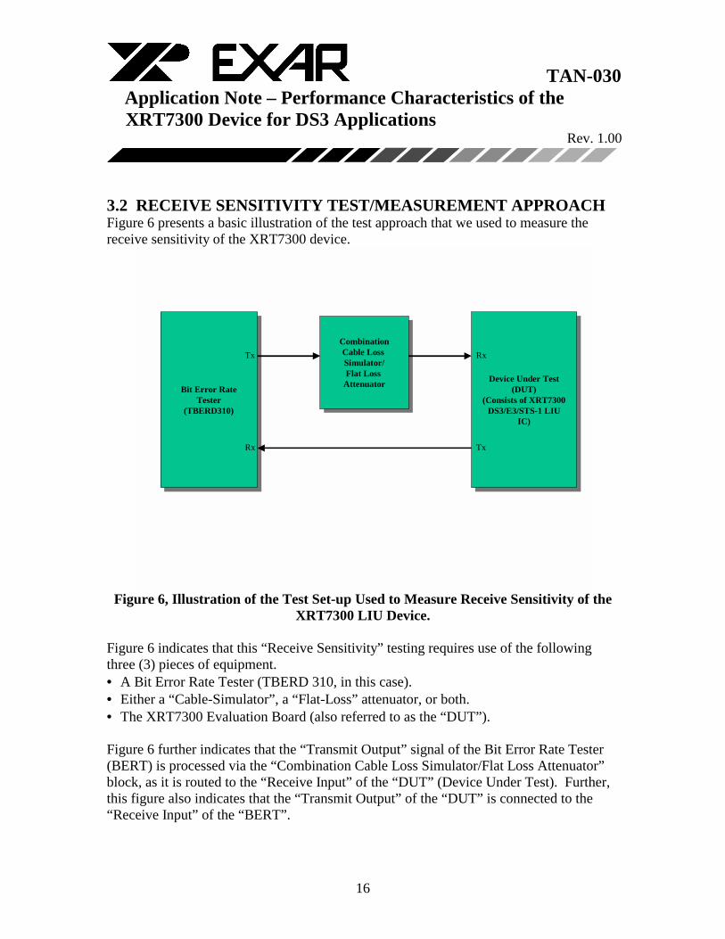
3.2 RECEIVE SENSITIVITY TEST/MEASUREMENT APPROACH Figure 6 presents a basic illustration of the test approach that we used to measure the receive sensitivity of the XRT7300 device.
Bit Error RateTester
(TBERD310)
Bit Error RateTester
(TBERD310)
CombinationCable Loss Simulator/Flat Loss
Attenuator
CombinationCable Loss Simulator/Flat Loss
Attenuator Device Under Test(DUT)
(Consists of XRT7300DS3/E3/STS-1 LIU
IC)
Device Under Test(DUT)
(Consists of XRT7300DS3/E3/STS-1 LIU
IC)
Tx
Rx
Rx
Tx
Figure 6, Illustration of the Test Set-up Used to Measure Receive Sensitivity of the
XRT7300 LIU Device. Figure 6 indicates that this “Receive Sensitivity” testing requires use of the following three (3) pieces of equipment. • A Bit Error Rate Tester (TBERD 310, in this case). • Either a “Cable-Simulator”, a “Flat-Loss” attenuator, or both. • The XRT7300 Evaluation Board (also referred to as the “DUT”). Figure 6 further indicates that the “Transmit Output” signal of the Bit Error Rate Tester (BERT) is processed via the “Combination Cable Loss Simulator/Flat Loss Attenuator” block, as it is routed to the “Receive Input” of the “DUT” (Device Under Test). Further, this figure also indicates that the “Transmit Output” of the “DUT” is connected to the “Receive Input” of the “BERT”.

TAN-030 Application Note – Performance Characteristics of the XRT7300 Device for DS3 Applications Rev. 1.00
17
Set-up Conditions which are not so obvious in Figure 6. In addition to the configuration that is illustrated in Figure 6, there are other set-up conditions that should also be noted. • The Transmit Output, of the BERT (TBERD 310, in this case) is always set to either “DSX-3” or “STSX-1” (depending upon whether we were testing at DS3 or STS-1 rates). • The XRT7300 device was tested with an “Unframed” 2^23-1 PRBS pattern (for DS3 applications); or with DS1 signals (each carrying a 2^23-1 PRBS pattern) which are VT-mapped into an “STS-1” signal. • The “XRT7300 Device” (residing within the DUT) is always configured to operate in the “Remote Loop-back” Mode. Hence, all “inbound” DS3/STS-1 traffic (which it receives) will undergo “Clock and Data Recovery” (via the Receive Section of the LIU IC). This “Recovered Clock” and Data will then be used to transmit DS3 or STS-1 data out to the BERT. • The Receive Equalizer (within the XRT7300 device) is always enabled. Table 1 indicates that testing (for both the DS3 and STS-1 rates) was performed under the following cable-loss/flat-loss conditions. • Pure Cable Loss from the “DSX-3/STSX-1 Cross-Connect” location. • Flat Loss, over and above “DSX-3/STSX-1 Cross-Connect” location” plus 450 feet of cable loss. • Pure Flat Loss from the “DSX-3/STSX-1 Cross-Connect” location. A more detailed explanation of each of these tests are presented below.
3.2.1 Pure Cable-Loss from the DSX-3/STSX-1 Cross-Connect Location When the System Manufacturer is interfacing the Receive Section of the XRT7300 device to the Cross-Connect system, he/she is aware of the following facts. • By definition, all DS3 or STS-1 line signals that are present at the Cross-Connect system are required to meet the “Isolated Pulse Template Requirements” (per Bellcore GR-499-CORE or ANSI TI.102 for DS3 applications, or Bellcore GR-253-CORE for STS-1 applications). • Further, these Bellcore documents state that the amplitude of these pulses (at the DSX-3 or STSX-1) can range in amplitude from 360mVpk to 850mVpk.

TAN-030 Application Note – Performance Characteristics of the XRT7300 Device for DS3 Applications Rev. 1.00
18
• Finally, these Bellcore documents stipulate that the DS3/STS-1 Receiving Terminal must be able to receive this “pulse-template” compliant line signal over a cable length of 0 to 450 feet from the DSX-3 or STSX-1 Cross Connect system. These facts are also reflected below in Figure 7.
Cross-ConnectSystemTransmitting
Terminal
Receiving Terminal
0 to 450 feet of Cable
Pulses that arecompliant to theIsolated DSX-3 orSTSX-1 Pulse TemplateRequirement
0 to 450 feet ofCable
DSX-3or
STSX-1
Figure 7, Illustration of the Typical Application for the System Installer.
The purpose of this portion of testing is two-fold. 1. To verify that the “Receive Section” of the XRT7300 device is capable of receiving a “DSX-3/STSX-1 Cross-Connect” signal which has been subjected to 450 feet of cable loss (per Bellcore requirements). 2. To quantify the amount of “Receive Sensitivity” margin (over and above these “Receive Requirements) the XRT7300 device has.
TAN-030 Application Note – Performance Characteristics of the XRT7300 Device for DS3 Applications Rev. 1.00
19
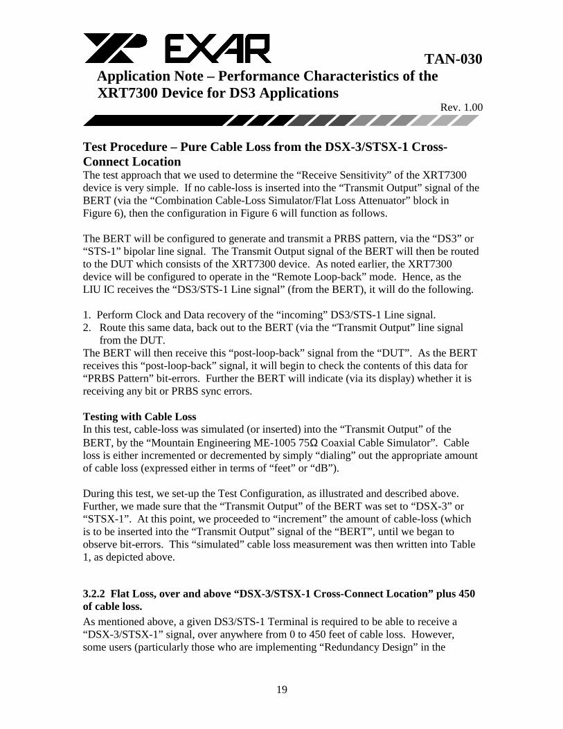
Test Procedure – Pure Cable Loss from the DSX-3/STSX-1 Cross-Connect Location The test approach that we used to determine the “Receive Sensitivity” of the XRT7300 device is very simple. If no cable-loss is inserted into the “Transmit Output” signal of the BERT (via the “Combination Cable-Loss Simulator/Flat Loss Attenuator” block in Figure 6), then the configuration in Figure 6 will function as follows. The BERT will be configured to generate and transmit a PRBS pattern, via the “DS3” or “STS-1” bipolar line signal. The Transmit Output signal of the BERT will then be routed to the DUT which consists of the XRT7300 device. As noted earlier, the XRT7300 device will be configured to operate in the “Remote Loop-back” mode. Hence, as the LIU IC receives the “DS3/STS-1 Line signal” (from the BERT), it will do the following. 1. Perform Clock and Data recovery of the “incoming” DS3/STS-1 Line signal. 2. Route this same data, back out to the BERT (via the “Transmit Output” line signal
from the DUT. The BERT will then receive this “post-loop-back” signal from the “DUT”. As the BERT receives this “post-loop-back” signal, it will begin to check the contents of this data for “PRBS Pattern” bit-errors. Further the BERT will indicate (via its display) whether it is receiving any bit or PRBS sync errors. Testing with Cable Loss In this test, cable-loss was simulated (or inserted) into the “Transmit Output” of the BERT, by the “Mountain Engineering ME-1005 75Ω Coaxial Cable Simulator”. Cable loss is either incremented or decremented by simply “dialing” out the appropriate amount of cable loss (expressed either in terms of “feet” or “dB”). During this test, we set-up the Test Configuration, as illustrated and described above. Further, we made sure that the “Transmit Output” of the BERT was set to “DSX-3” or “STSX-1”. At this point, we proceeded to “increment” the amount of cable-loss (which is to be inserted into the “Transmit Output” signal of the “BERT”, until we began to observe bit-errors. This “simulated” cable loss measurement was then written into Table 1, as depicted above.
3.2.2 Flat Loss, over and above “DSX-3/STSX-1 Cross-Connect Location” plus 450 of cable loss. As mentioned above, a given DS3/STS-1 Terminal is required to be able to receive a “DSX-3/STSX-1” signal, over anywhere from 0 to 450 feet of cable loss. However, some users (particularly those who are implementing “Redundancy Design” in the
TAN-030 Application Note – Performance Characteristics of the XRT7300 Device for DS3 Applications Rev. 1.00
20
Receive Direction) will require even greater receive sensitivity from the XRT7300 LIU IC. A common approach to “Redundancy Design” in the “Receive Direction” is to use a “Cable-Splitter” in the “incoming” (Receive) line signal. This “cable-splitter” will permit the routing of a single “incoming” line signal into the receive inputs of two separate DS3/STS-1 line cards (in parallel). However, this cable-splitter inserts a flat loss of about 6dB into the line signal that each these two line cards will receive. Hence, these particular customers require that the LIU IC be capable of receiving the “afore-mentioned DSX-3/STSX-1 plus 450 feet of cable-loss” signal; with an additional 6dB of flat-loss. The purpose the this particular test is to determine the following. 1. If the XRT7300 device is capable of meeting this combined “flat-loss” and “cable-loss” requirements. 2. How much “flat-loss” Receive Sensitivity margin does the XRT7300 device have
over and above these “Receive Redundancy” design requirements. In order to perform this particular test, we had to execute the following procedures. a. Insert 450 feet of cable-loss, between the “Transmit Output” of the “BERT” and the “Receive Input” of the “DUT”. b. In addition to this “450 feet of cable-loss”, we also connected some “VHF Flat Loss Attenuators”, in series, between the “Cable Simulator” and the “Receive Input” of the DUT. c. Afterwards, we began to increase the amount of “Flat-Loss” into the signal path, until the BERT started to reflect bit errors, on its display. The results of this particular test are presented in Table 1.
3.2.3 Pure Flat Loss from the “DSX-3/STSX-1 Cross-Connect” Location. The purpose of this test is to simply test out the “AGC” (Automatic Gain Control) block within the Receive Section of the XRT7300 device. When performing this measurement, we connected everything up as indicated in Figure 6. However, instead of using the “Mountain Engineering” cable simulator, we strictly used the “VHF Flat Loss” attenuator. In order to perform this particular test, we had to execute the following procedure.

TAN-030 Application Note – Performance Characteristics of the XRT7300 Device for DS3 Applications Rev. 1.00
21
a. Connect up the “BERT”, the “Flat-Loss” Attenuator, and the “DUT” as illustrated in Figure 6. b. Make sure that the “Flat-Loss” Attenuator is initially set to “0dB” and verify that the BERT is not receiving any bit errors.. c. Begin increasing the amount of flat-loss, into the “signal path” (via the “flat-loss” attenuator) until the BERT starts to indicate the occurrence of bit errors (via its display). The results of this measurement are indicated in Table 1.
TAN-030 Application Note – Performance Characteristics of the XRT7300 Device for DS3 Applications Rev. 1.00
22
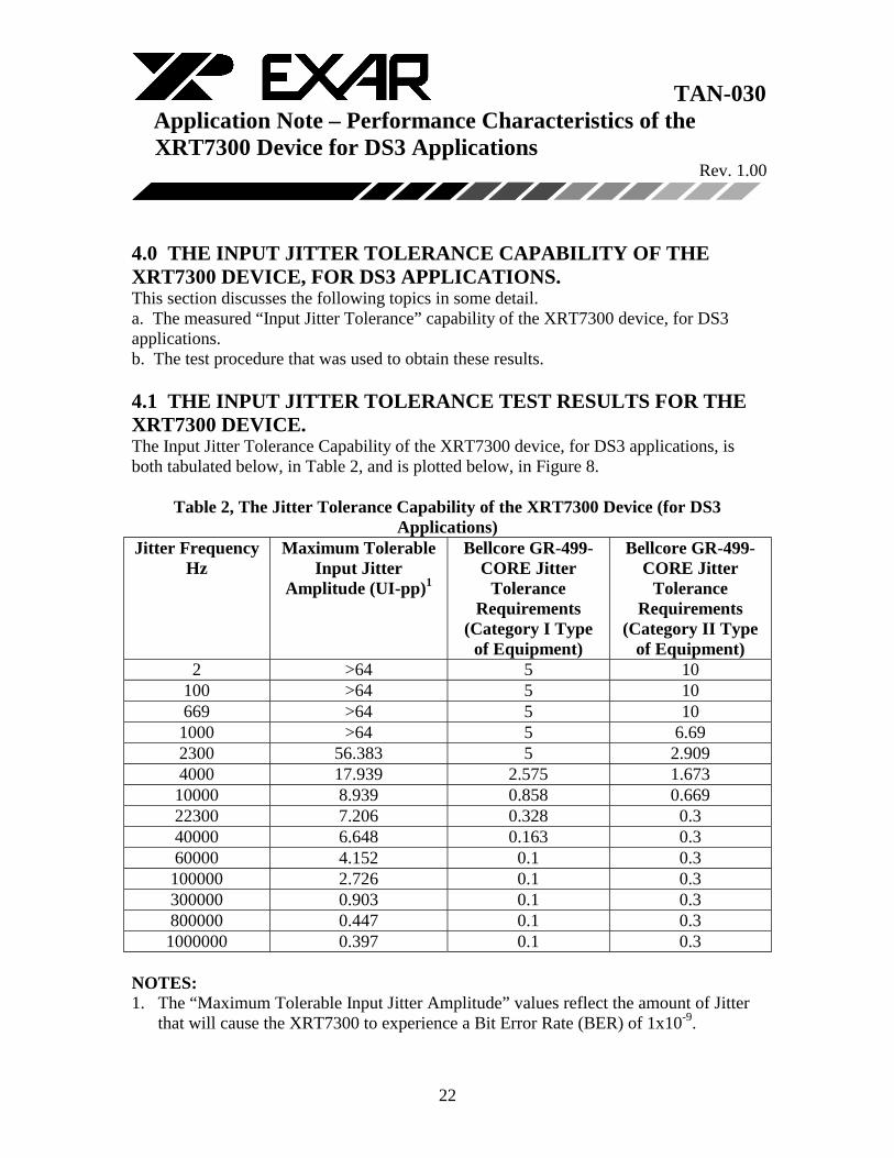
4.0 THE INPUT JITTER TOLERANCE CAPABILITY OF THE XRT7300 DEVICE, FOR DS3 APPLICATIONS. This section discusses the following topics in some detail. a. The measured “Input Jitter Tolerance” capability of the XRT7300 device, for DS3 applications. b. The test procedure that was used to obtain these results. 4.1 THE INPUT JITTER TOLERANCE TEST RESULTS FOR THE XRT7300 DEVICE. The Input Jitter Tolerance Capability of the XRT7300 device, for DS3 applications, is both tabulated below, in Table 2, and is plotted below, in Figure 8.
Table 2, The Jitter Tolerance Capability of the XRT7300 Device (for DS3 Applications)
Jitter Frequency Hz
Maximum Tolerable Input Jitter
Amplitude (UI-pp)1
Bellcore GR-499-CORE Jitter
Tolerance Requirements
(Category I Type of Equipment)
Bellcore GR-499-CORE Jitter
Tolerance Requirements
(Category II Type of Equipment)
2 >64 5 10 100 >64 5 10 669 >64 5 10 1000 >64 5 6.69 2300 56.383 5 2.909 4000 17.939 2.575 1.673 10000 8.939 0.858 0.669 22300 7.206 0.328 0.3 40000 6.648 0.163 0.3 60000 4.152 0.1 0.3 100000 2.726 0.1 0.3 300000 0.903 0.1 0.3 800000 0.447 0.1 0.3 1000000 0.397 0.1 0.3
NOTES: 1. The “Maximum Tolerable Input Jitter Amplitude” values reflect the amount of Jitter
that will cause the XRT7300 to experience a Bit Error Rate (BER) of 1x10⁻⁹.

TAN-030 Application Note – Performance Characteristics of the XRT7300 Device for DS3 Applications Rev. 1.00
23
2. 64UI-pp is the maximum amount of “Input Jitter Amplitude” that our Test Equipment (e.g., the W&G ANT-20) can insert into the DS3 line signal.
3. The Test Set-up was as listed below. • Test Equipment Output Setting = DSX-3 • Cable Loss (between Test Equipment Output and RTIP/RRING inputs) = 0 feet. • Test Equipment used – W&G ANT-20. • Test Pattern = 2^23-1 PRBS. The data, which is tabulated in Table 2 is plotted below in Figure 8.
J itte r To le r anc e o f the XR T7 300 D evic e (D S3 A pplic a tions)
0.1
1
10
100
1 10 100 1000 10000 100000 1000000
J itte r Fre que ncy , H z
Inpu
t Ji
tter
Am
plit
ude,
UIp
Maxim um Input Jitter To leranc e - XR T 7300
B ellc ore GR -499-C O R E R equirem ent - C at IB ellc ore GR -499-C O R E R equirem ent - C at II
Figure 8, A Plot of the “Jitter Tolerance Capability” of the XRT7300 Device (for
DS3 Applications) How to Read This Plot The “Pink Curve” (e.g., marked with “Square” boxes) and the “Yellow Curve (e.g., marked with “Triangular” boxes) are the Jitter Tolerance Requirements per Bellcore GR-499-CORE (for DS3 Applications). The “Maximum Jitter Tolerance” measurements for

TAN-030 Application Note – Performance Characteristics of the XRT7300 Device for DS3 Applications Rev. 1.00
24
the XRT7300 device (for DS3 applications) is presented in the “Blue Curve” (e.g., marked with the “Diamond” boxes). This specification document requires that the “Jitter Tolerance Measurements” (see the “Blue Curve”) always be “above” (or NORTH) of the “Pink Curve” and the “Yellow Curve” over all ranges of “input” Jitter Frequencies.
TAN-030 Application Note – Performance Characteristics of the XRT7300 Device for DS3 Applications Rev. 1.00
25
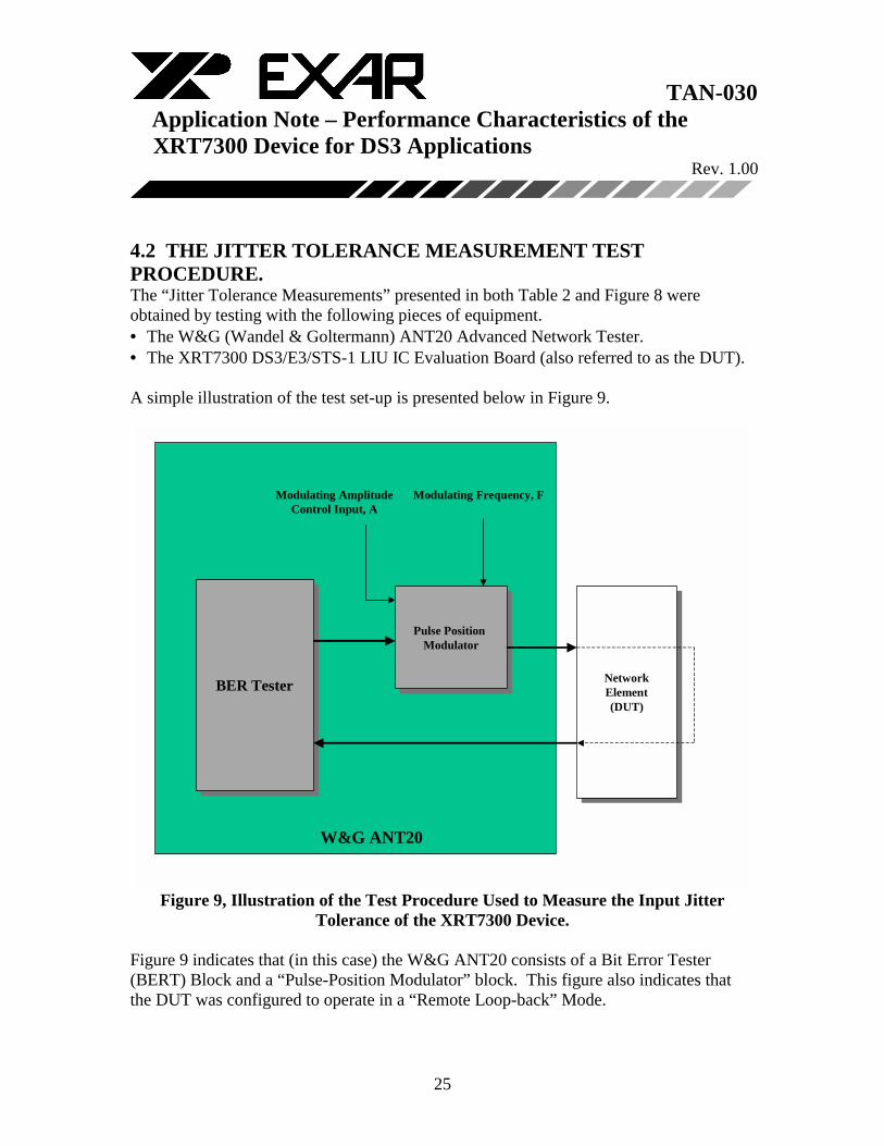
4.2 THE JITTER TOLERANCE MEASUREMENT TEST PROCEDURE. The “Jitter Tolerance Measurements” presented in both Table 2 and Figure 8 were obtained by testing with the following pieces of equipment. • The W&G (Wandel & Goltermann) ANT20 Advanced Network Tester. • The XRT7300 DS3/E3/STS-1 LIU IC Evaluation Board (also referred to as the DUT). A simple illustration of the test set-up is presented below in Figure 9.
BER TesterBER Tester
Pulse Position Modulator
Pulse Position Modulator
NetworkElement(DUT)
NetworkElement(DUT)
Modulating Frequency, FModulating AmplitudeControl Input, A
W&G ANT20
Figure 9, Illustration of the Test Procedure Used to Measure the Input Jitter
Tolerance of the XRT7300 Device.
Figure 9 indicates that (in this case) the W&G ANT20 consists of a Bit Error Tester (BERT) Block and a “Pulse-Position Modulator” block. This figure also indicates that the DUT was configured to operate in a “Remote Loop-back” Mode.

TAN-030 Application Note – Performance Characteristics of the XRT7300 Device for DS3 Applications Rev. 1.00
26
NOTE: This particular loop-back mode was realized by configuring the XRT7300 device into the “Remote Loop-back” Mode. The W&G ANT20 Tester is a very flexible machine that can be configured to automatically measure the “Input Jitter Tolerance” of a given piece of Network Equipment over various data rates. This tester was used to measure the “Jitter Tolerance Capability” of the XRT7300 device, for DS3 rates. Figure 9 presents a “theoretical” illustration as how the W&G ANT20 would measure the input jitter tolerance of the XRT7300 device. This figure indicates that the W&G ANT20 Tester consists of the following two blocks. • A Bit Error Rate Tester (BERT) which can be configured to transmit and receive a DS3 line signal. • A Pulse-Position Modulator Block. The “BERT” block can be configured to transmit and receive a PRBS pattern, over a DS3 line signal. As this DS3 line signal is routed to the DUT; it passes through the “Pulse-Position Modulator” block. The purpose of the “Pulse Position Modulator” block would be to modulate the “position” of each of these “outbound” pulses within the DS3 line signal. The “position” of each of these pulses could be modulated by both “amplitude” (in terms of UIpp) and “frequency” (in terms of Hz). NOTE: By modulating the position of each of these pulse (within the DS3 line signal), the W&G ANT20 is introducing jitter into the “Transmit Output” DS3 signal. This “jittery” signal will be routed to the “Receive Input” of the XRT7300 LIU IC. The W&G ANT20 measured the Jitter Tolerance capability of the XRT7300 device by executing the following steps. STEP 1. The W&G ANT20 selects a “user-defined” jitter frequency. STEP 2. The W&G ANT20 then proceeds to (via the “Pulse-Position Modulator” block) modulate the position of each “Transmit Output” pulse (from the BERT block) at this particular jitter frequency. STEP 3. The W&G ANT20 would then proceed to increase the amplitude of this “pulse-position modulation” (while keeping the “jitter frequency” constant); until the BERT block begins to detect a Bit Error Rate (from the LIU IC) of 1x10⁻⁹. STEP 4. The W&G ANT20 would then slightly reduce the amplitude of this “Pulse-Position Modulation” until the bit-errors went away. STEP 5. This particular “Pulse-Position Modulation” amplitude is then converted into a “Maximum Tolerable Input Jitter (expressed in terms of “UI-pp”); and is recorded by the W&G ANT20.
TAN-030 Application Note – Performance Characteristics of the XRT7300 Device for DS3 Applications Rev. 1.00
27
STEP 6. The W&G ANT20 then selects a different “user-defined” jitter frequency and then proceeds to repeat “STEPS 2” through “5” of the “above-mentioned” procedure. When this whole procedure is completed, for the user-defined range of frequencies, the W&G ANT20 will “halt” this testing and will display data which is very similar to that presented within Table 2.