application note - nj7p.orglected under program control. the flexibility of the 8255 is due to the...
TRANSCRIPT

APPLICATION NOTE
I I @ Intel Corporation, 1976
PRICE $1 00

Contents
8255 Programmable Peripheral Interface Applications
. . . . . . . . . . . . . . . . . . . . . . . . . INTRODUCTION 1
. . . . . . . . . . . . . . . . . . . . . . . . . . . . . OVERVIEW 1
8080 CPU MODULE INTERFACE . . . . . . . . . . . . 1
PERIPHERAL INTERFACE SECTION . . . . . . . . 3
. . . . . . . . . . . . . . . INTERNAL LOGIC SECTION 4
Mode Definition . . . . . . . . . . . . . . . . . . . . . . . . 4 Bit SetIReset . . . . . . . . . . . . . . . . . . . . . . . . . . . 5
INTERRUPT CONTROL LOGIC STATUS . . . . . . . . . . . . . . . . . . . . . . . . . . . . . . . WORDS 6
. . . . . . . . . . . . SOFTWARE CONSIDERATIONS 8
MODE 0 . STATUS DRIVEN PERIPHERAL INTERFACE . . . . . . . . . . . . . . 10
8255 To Peripheral Hardware Interface . . . . . . 10 8080 CPU Module To 8255 Interface . . . . . . . 10 Mode 0 Interface Software . . . . . . . . . . . . . . . 12
. . . . . . . . . . . . . . . . . . . Summary /Conclusions 13
MODE 1 . INTERRUPT DRIVEN PRINTER INTERFACE . . . . . . . . . . . . . . . . . 15
CPU Module To 8255 Interface . . . . . . . . . . . . 15 8255 To Peripheral Interface . . . . . . . . . . . . . . 15 Mode 1 Software Driver . . . . . . . . . . . . . . . . . 16
. . . . . . . . . . . . . . . . . . . Surnmary/Conclusions 17
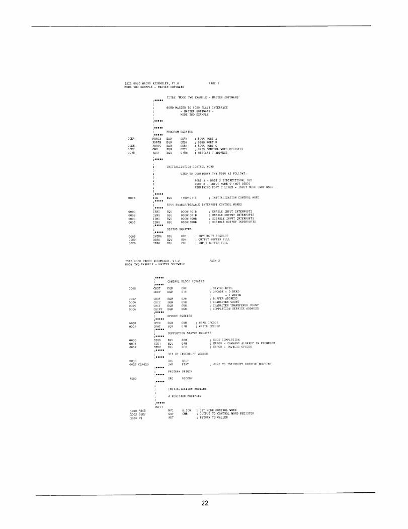
MODE 2 . 8080 TO 8080 INTERFACE . . . . . . 20
Hardware Discussion . . . . . . . . . . . . . . . . . . . . 20 . . . . . . . . . . . . . . . . . . . Software Discussion 20 . . . . . . . . . . . . . . . . . . Summary/Conclusions 20
APPENDIX A . 8255 QUICK . . . . . . . . . . . . . . . . . . . . . . . . . REFERENCE 27
lntel Corporat~on assumes no responsibility for the use of any circuitry or software other than circuitry or software embodled i n an lntel product . No other circuit patent licenses ere implied .

Related Intel Publications
"Intel 8080 Microcoinputer Systems User's Manual"
"Memory Design Handbook"
"Using the 825 1 Universal Synchronous/Asyncl~ronous Receiver/Transmitter"


When a system utilizing the linear select scheme is implemented, a maximum of six 110 devices may be s-lected. If more than six I/O devices must be addressed, the six device select bits must be en- eodtd t o generate a maximum of 64 device select lines. Note that when large systems are imple- mented, bus loading considerations may require that bus drivers be included in the CPU module. The MCS-80 component family contains parts which are designed t o perform this function (82 16, 8220).
The 8255 110 read (RD) and 110 write (m) sign2ls may be directly driven by the 8228. This results in an isolated I/O architecture where 8080 Input/Output instructions are used t o reference an independent 110 address space. An alternate ap- proa211 is memory mapped 110. This architecture treats an area of memory as the 110 address space. The memory mapped I/O architecture utilizes 8080 memory reference instructions t o access the 110 address space. Interfacing with the 8080 is outlined in Chapter 3 of the "8080 Microcomputer User's Manual".
The [nost important feature of the 8255 to 8080 CPU Module Interface is that for small system designs the 8255 may be interfaced directly t o the
standard MCS-80 component family with no external logic. Minimum external logic i s required in large system designs.
p, 1 A6 1 A5 1 A4 I A3 1 A, A1 A0 1 C I I --
I 8255 = 1 SeIec1
0 = Select
I 1 = No Select
i 8255 - 2 Select
0 = Select 1 = NO Select
Spare Select Lmex (other 8255's or 110 Devcerl Set ro 11 11 Blnary
Hexajec~mlal Port Select Character
Port B 8255 =1 Part C 8255 = 1 F A Control Word Reg~rter 8255 =1 FB
Port A 8255 =2 1 Par1 8 8255 ~2 1 1 Port C 8255 2 2 Control Ward Reglrter 8255 =2 --
Figure 4. 110 Port Select Characters
Figure 3. Linear Select 8255 Interconnect

PERIPHERAL INTERFACE SECTION
The peripheral interface section contains 24 per- ipheral interface lines, buffers, and control logic. The characteristics and functions of the interface lines are determined by the operating rnode se- lected under program control. The flexibility of the 8255 is due to the fact that the device is pro- grammable. Three modes of operation may be selected under prograrn control: Mode 0 - Basic Input/Output, Mode 1 - Strobed Input/Output with irltcrrupt support, and Mode 2 - Bidirectional bus with interrupt support. Through selecting the correct operating mode, the interface lines may be configured to fulfill specific interface require- ments. The characteristics of the interface lines within each mode rnust be understood so that the designer may utilize the 8255 t o achieve the most efficient design. Table I lists the basic features of the peripheral interface lines within each mode group. Figure 5 shows the grouping of the periph- eral interface lines within each mode.
Table I. Features of Peripheral lnterface Lines
Mode 0 - Basic InputIOutput
Two 8-bit ports
1 Two 4-bit ports with bit setireset capability I
I Outputs are latched
Inputs are not latched
( Mode 1 - Strobed Input/Output I One or two strobed ports
Each Mode 1 port contains:
8-bit data port 3 control lines lnterrupt support logic
Any port may be input or output
I f one Mode 1 port is used, the remaining 13 lines may be configured in Mode 0.
I f two Mode 1 ports are used, the remaining 2 bits may be input or output with bit setireset capability.
Mode 2 - Strobed Bidirectional Bus
One bidirectional bus which contains:
8-bit bidirectional bus supported by Port A 5 control lines Interrupt support logic Inputs and outputs are latched
The remaining 11 lines may be configured in either Mode 0 or Mode 1.
One feature of Port C is important t o note. Each Port C bit may be individually set and reset. Through the use of this feature, device strobe.; may be easily generated by software without utilizing extcrnal logic. Thc Mode 1 and Mode 2 conf~gura- tions use a number of the Port C lines for interrupt control lines. Thus, the 8255 contains a largt por- tion of the logic required to implement an inter- rupt driven 110 interface. This feature sim1,lifies interrupt driven hardware design and saves a signi- ficant amount of the external logic that is normally required when less powerful 110 chips are usttd. In fact. the design examples contained in this applica- tion note describe how interrupt driven inte~faces may be designed such that the only interrupt con- trol logic required is that contained in the 8255.
L _ _ _ ADDRESS BUS I I-
A I I
CONTROL BUS
MODE l
PB7-PBO PC3-PCO PC7-PC4 PA7-PAO
MODE 1 -
PB7-PBO lNTRA lBFA mA PA7-PAO 110 OR
CONTROL , PORT A CONTROL E I
/ DIREC'IONAL PORT B MAY BE B I S MODE 0 OR MODE 1
Figure 5. Grouping of Peripheral Interface Lines
3

INTERNAL LOGIC SECTION
The internal logic section manages the transfer o f data and control information on the internal data bus (refer t o Figure 2). If the port select lines (A l and 40) specify Ports A, B, or C, the operation is an 1 ' 0 port data transfer. The internal logic will select the specified IJO port and perform the data tran5fer between the 110 port and the CPU inter- face. As was previously mentioned, both the fun c- tion; 1 configuration of each port and bit setlreset on Port C are controlled by the systenl's software. Whe I the control word register is selected, the internal logic performs the operation described by the ;ontrol word. The control word contains an opcode field which defines which of the two func- t ion~ , are t o be performed (mode definition o r bit setlreset).
Mode Definition
When the opcode field (Bit 7) of the control word is equal t o a one, tlie control word is interpreted by 111e 8255 as a mode definition control word. The mode definition control word (shown in Fig- ure 6) is used t o specify the configuration of the
CONTROL WORO
1 4
PORTC (LOWFR - PC3PCO) 1 = INPUT 0 =OUTPUT 1 PORT B 1 = INPUT 0 = OUTPUT
MODE SELECTION O = M O D t O 1 =MODE 1 I
GROUP A
PORTC (UPPFR - PC7PC4) +I 1 = INPUT 0 = OUTPUT I PORT A +I 1 = INPUT 0 = OUTPUT
MODE SELECTION 0 0 = MODE 0 01 = MODE 1 1X =MODE 2 -1
24 8255 peripheral interface lines. The system's software may specify the modes of Port A and Port B independently. Port C may be treated independ- ently o r divided into two portions as required by the Port A and Port B mode definitions.
Example # I : This example demonstrates how a mode control word is constructed and issued t o an 8255. The mode control word is passed to the device through the use of an ou tpu t instruction that references an 8080 110 port address. The value of the 110 port address is determined by the 8080 CPU interface implemented. This example refer- ences the 110 port addresses realized by tlie simple 8080 t o 8255 interface shown in Figure 3.
If an 8255 is t o be configured through the use of the mode control word interface as:
Port A Mode 0 Input Port B Mode 1 Output Port C Bits PC7-PC4 Output Port C Bit 3 Input
The following mode control word is used:
Port B Mode 1 - 1
Part C Bqtr PC7-PC4 Outpl~t = 0
Port A Input = 1
Part A Mode 00 -- Opcode Made Set = 1
Mode Control Ward = lOOlOlO1 Binary
The assembly language program is:
CWR EOU OFBH ; 8255 "1 CONTROL WORD REGISTER , *.... , ISSUE MODE CONTROL WORD .....
M V I A.10010101B : G E T MODE CONTROL WORD OUT CWR ;OUTPUT TO 8255 ftl CONTROL WORD
.REGISTER
Figure 6. Mode Definition Control Word -
4

Bit Set/Reset
When the opcode field (Bit 7) of the control word is equal t o a zero, the control word is interpreted by the 8255 as a Port C bit setlreset command word (see Figure 7). Through the use of the bit setlreset command, any of the 8 bits o n Port C may be independently set or reset. Note that con- trol word bits 6-4 are no t used. Bits 6-4 should be set t o zero.
Corztrol word (see Figure 7).
1 1 L s e t Bnt = 1 R e w 811 = 0
Brr Selecr = 011 IBonary! = 3 IDeclmal
Not Used = 000 IBlnary!
Blr SetIR~rer Dpcode = 0
The control word for set Porr C blc 3 or 000001 11 binary The control word for reset Port C h ~ t 3 Ir 00000110 binary
The assembly language program is:
CONTROL WORD
l ~ ~ , D 6 ~ D 5 1 D 4 ~ D 3 ~ q 2 1 D 1 ! D i I
- Y -- SET RESET FLAG
BIT SELECT
0 1 0 BIT 2 0 1 1 RIT 3 1 0 0 BIT 4 1 0 1 BIT 5 1 1 0 1 1 1
~ OP CODE
L -1 O B I T SETIRESET I
CWR EOU OFBH ..... 8255 -1 CONTROL WORD REGISTER
...*. SET BIT 3
MVI A OOOOOlllB GET SET BIT 3 CONTROL WORD OUT CWR OUTPUT TO8255 = I CONTROL WORD IiEGlSTER
..... RESET BIT 3
M V I A.OOOOO110B . GET RESET B I T 3 C D N T R O L WORD OUT CWR OUTPUT TO 8255 =1 CONTROL WORD I(EG1STER
NOTE: An MVI instruction is used t o load the re:.et bit 3 control word into the A register. Since it i. known that the set bit control word is already in the A register, a "DCK A" Instruction could be used t o generate the correct control word and s w e one byte of code.
000001 11 - 1 = 000001 1 0 (RESET BIT 3 CON- T R O L WORD)
Example #3: This example d e m o n s t r a t s one simple method of performing a bit set/resef opera- tion o n Ports A and B. The state of any ou tpu t port may be determined by reading the port. The assembly language program which may be ~ s e d t o setlreset Port A o r B bits is:
Figure 7. Bit SetIReset Control Word
Example #2: This cxample demonstrates how a Port C bit setlreset control word is constructed and issued t o an 8255 . The bit setlreset control word is passed t o the device through the use of an ou tpu t instruction that references an 8080 I /O port ad- dress. The value of the 110 port address is deter- mined by the 8080 CPU interface implemented. This example references the 110 port addresses realized by the simple 8080 t o 8255 interface shown in Figure 3.
PORTA EOU OF8H ..... : 8255 :1 PORT A
..... SET B I T 0
IN PORTA GET STATE OF PORT OR1 01H SET BIT 0
..... OUT PORTA :OUTPUT TO PORT
*.... RESET BIT 0
IN PORTA : GET STATE OF PORT AN1 OFEH , RESET B I T 0
OUT PORTA OUTPUT TO PORT

INTERRUPT CONTROL LOGIC STATUS WORDS As previously mentioned, the 8255 Mode 1 and Mode 2 configurations support interrupt control logic. If a read of Port C is issued when the 8255 is configured in Mode 1, the software will receive.the Mode 1 status word shown in Figure 8 . The bits in the status word correspond t o the state o f the asso- ciated Port C lines (buffer full, interrupt request, etc.). The INTE bit shown in the status word corre- sponds t o the interrupt enable flip-flop contained in the 8255 . This signal is not available externally. The s:ructure o f the Mode 1 status word varies as a f u n c t ~ o n of the mode of the 8 2 5 5 . Example #4 shows the status word which results from reading Port (' from an 8255 which is configured with Port A Mode 1 input and Port B Mode 1 output .
Port B Output = 0
1 I I 1 Port B Mode 1 = 1
I I I L Port C Bits 6 & 7 Outpufi
I L Port A Input = 1
I Port A Mode = 01
L Opeode Mode Set = 1
Mode Control Word - 10110100 Elnary
After the 8255 mode control word has been issued, a READ of Port C will obtain the following Mode I status word:
PORT C BITS
GROUP A GROUP B ! STATOS 1 STATUS
( INPUT PORT
7- bp 1
t -- D2 D l Do -1
OUTPUT PORT
-7 - DZ D l Do
4 - . "7 D6 D5 D4 D3
Figure 8. Mode 1 Status Word
110
Exa~~iple #4 - MODE 1 STATUS WORD
If an 8255 is t o be configured through the use of the rn'lde control word interface as:
Port A Mode 1 Input Port B Mode 1 Output Port C Bits 6 & 7 Output
The following mode control word is used:
I 1 110 110 I F B ~ I N T E ~ I N T R ~ / I N T E B 0-B I N T R ~ . - ,
Group A Group B
OUTPUT
rR- D7 D6 D5 D4 D3
I10 ) lBFA
NOTE: T h e Port C 1 / 0 bits D7 and Dg should be modified through the use of t h e Port C bit set/reset com- mand word. If a write t o Por t C is issued, t he INTEA and INTEB bits may be inadvertently modified by the user. T h e IBFA, INTRA, OBFB, and INTRB bits will not be modified by either a write t o Port C o r a bit set/reset command. These four bits always reflect the state of the interrupt control logic.
Note that the Mode 2 status word (shown in Fig- ure 9) differs from the Mode 1 status word. The format of the status word data bits Dl-Do are defined by the specification of the Port B configu- ration. Example #5 shows the structure of the Mode 2 status word when the 8255 is configured with Port A Mode 2 (bidirectional bus) and Port B Mode 1 input.
INTEA
The Mode 1 and Mode 2 status words reflect the state of the interrrupt logic supported by the 8255 .
INTRA

Example #6 demonstrates how the interrupt After the 8255 mode control word has been is- enable bits are controlled through the use of the sued, a read of Port C will obtain the following Port C bit setlreset feature. The application exam- Mode 2 status word: ples provide a more detailed explanation of the use of the Port C status word in the Mode 1 and Mode 2 configurations.
GROUP A STATUS 1
PORT C BITS
7-
DZ Do
MODE 1 INPUT PORT
7
MODE 1 OUTPUT
PORT 1
D7
Figure 9. M o d e 2 Status Word
'4
Example #5 - MODE 2 STATUS WORD
D6
If the 8255 is t o be configured as follows:
Port A Mode 2 Bidirectional Bus Port B Mode 1 Input
D5 D3
The following mode control word is used:
D2
No t Used = Sec to 0
Port B Input = 1
Port B Mode 1 = 1
Not Used = Set to 00
Port A Mode 2 = 10
Dpcode Mode Set = 1
Mode Control Word = 11000110 Bmnary.
Example #6 - MODE 2 lNTEKRUPT ENABLE/ DISABLE
The Mode 2 status word shown in Figure 0 con- tains two interrupt enable bits:
'37 0 6 '35 0 4 '33 0 2 D l Do
INTEl - Bit 6 - Enable output interrupts INTE2 - Bit 4 - Enable input interrupts
~ ~ ~ ~ ~ ~ s R : " ~ ~
Bit set/reset control words may be constructed which may be used t o control the INTE bits.
Set Bit 6 (Enable Output Interrupts ) = 0000 1 10 1 Binary
. '-- Group A Group B
Reset Bit 6 (Disable Output Interrupts) = 0000 l 100 Binary
lNTRB
Set Bit 4 (Enable Input Interrupts) = 0000 100 1 Binary
lNTEl
Reset Bit 4 (Disable Input Interrupts) = 0000 I000 Binary
INTE2 lBFA
The control words shown were constructed from the standard bit set/reset format shown ill Fig- ure 7.
The value of CWR used in the following program example corresponds t o the 8080 configuration shown in Figure 3.
CWR EOU OFBH .*.*.
8255 = l CONTROL WORD REGISTER
....* ENABLE INTERRUPTS FOR MODE 2 OUTPUT [SET PORT C BIT 61
lNTRA
M V I A. 00001 l O l B . GET SET BIT 6 CONTROL WORD OUT CWR . OUTPUT TO 8255 -1 CONTROL WORD H t GlSTER
r . * * *
*.... OISABLE INTERRUPTS FOR MODE 2 OUTPUT IRESETPORTC B I T 6 1
INTEE
M V I A.OOOO1lOOB GET RESET B I T 6 C O N T R O L WORD OUT CWR OUTPUT TO6255 = l CONTROL WORD REGISTER
IBFB

SOFTWARE CONSIDERATIONS
Regrirrlless of the mode selected, the software must always issue the cor rec t .n~ode control word after a reset of the device. Generally. an initialization rout i r~e is constructed which issues the correct mode control word, sets up the initial state of the contr'11 lines, and initializes any program internal data.
Many of the software requirements of the 8255 vary as a f i~nct ion of the mode selected. The sirnp11:st mode supported by the device is Mode 0 (Basic Input/Output). Generally, Mode 0 is used for si nple status driven device interfaces (no inter- r ~ ~ p t s ' . Figure 10 illustrates sample software that could be used t o support such interfaces. Most deviccss support a BUSY o r READY signal which is used t o determine when the device is ready t o input o r output data and a DATA STROBE which is used t o recl~~est data transfer (DATA STROBE may :asily be generated with the Port C bit set/ reset feature). In the Mode 0 configuration, Ports A an1 B are used t o input/output byte oriented data. Port C is used t o input 8255 status, periph- eral status and t o drive peripheral control lines.
When the Mode 1 and Mode 2 configurations are used, the software is generally required t o support interrupts. Software routines written for an inter- rupt rlriven environment tend t o be more complex than ;tatus driven routines. The added complexity is duf. t o the fact that interrupt driven systems are constructed such that other software tasks are run while the I /O transaction is in progress. A software rou t i l~e that controls a peripheral device is gener- ally referred t o as a device driver. One method of iniplt.menting an interrupt driven device driver is t o partition thc device driver into a "Command Proc- essor" and an "Interrupt Service Routine". The com~liand processor is the module that validates
INPUT 0
RETURN 0
OUTPUT (-) o d BUSY
SET UP
STROBE
RETURN 0
Figure 10. Sample Status Driven Software Flowchart
and initiates user program requests t o the device driver. A common method of passing information between the various software programs is t o have the r eq~~es t i ng routine provide a device control block in memory. A sample device control block is shown in Table 11.
Table II. Sample Device Control Block
Status
r NAME
1 This 1-byte field is used to transmit the status of the I10 transaction (busy, I DESCRIPTION
I ( complete, etc.). I Op ,ode This 1-byte field defines the type of 110 (READ, WRITE, etc.). i I Bu'fer Address I This 2-byte field specifies the source/destination of the data block. ~ Character Count This 1-byte field i s a count of the number of characters involved in the transaction. I Chjracter Transferred Count 1 This 1-byte count of the number of characters which were actually transferred. I Covpletion Address This 2-byte field is the address of the user supplied completion routine which will
be called after the I10 has been performed.
8

The command processor validates the transaction and initiates the operation described by the control block. Control is then returned t o the requestor so that other processing rnay proceed The interrupt service routine processes the remainder of the transaction.
The interrupt service routine supports the follow- ing functions:
1 . The state of the machine (registers, status, etc.) must be saved so that it may be restored after the interrupt is processed.
2. Tlie source of the interrupt must be determined. Tlie Iiardware may support a register which indi- cates the interrupting device. or the software may poll the devices through interrogating the Port C status word of each 8255.
3. Data must be passed t o or from the device.
4. Control must be passed t o the requestiilg routine at the completion of the 110.
5. The statc of the machine must be restored be- fore returning t o the interrupted program.
START (7 VALID
TRANSACTION,
STATE OF DEVICE & DEVICE CONTROL BLOCK
i DECODE OPCODE 0
ERROR
ROUTINE
OPCODE 1 1 OPCODE 0
STAHT START START
ENABLE INTERRUPTS
RETURN TOCALLER E-
Figure l l . Command Processor
Figures 1 1 and 12 are simplified flowchart: of one of the many methods of implementing c o x m a n d processor and interrupt service routine modules.
The rest of this application note presents !,pecific application exaniyles. All o f the 8080 assembly language programs supplied with the application examples use the standard Intel 8080 assembly language mnemonics. The programs discus5ed use thc program equate statement t o specify all hard- ware related data. Equate statements are i sed so that all references t o an 110 port may be c laiiged through a simple reassignment of the port xidress in the equate statenlent.
INTERRUPT
Y MACHINE
1 YES I
INPUT/ OUTPUT
CHARACTER - RESTORE MACHINE
ENABLE INTERRUPTS
RETURN 0 Figure 12. Interrupt Service Routine

MODE 0 - STATUS DRIVEN PERIPHERAL INTERFACE This design example shows how a single 825.5 in Mode 3 rnay be used to develop a status driven interfa:e (no interrupts) for the Centronics 306 character printer, the Remex paper tape punch, and the Remex paper tape reader.
8255 To Peripheral Hardware Interface
The first step in the design is t o examine the speci- fication for tlie peripheral devices and identify the contrcl and data signals which must be supported by t h ~ : interface. Table 111 lists the signals which were ;hose11 to be supported by the 8255 inter- face. ,411 three of the devices support the standard
Table I I I . Peripheral Interface Signals
P R I N T E R
Idame: D A T A O- D A T A 7
Def in i t ion: l n p u t data levels. A high signal represents a b inary 1 and a l o w signal represents a b inary 0. These eight lines are the data lines t o t h e pr in ter . -
l a m e : DATA STROBE
Def in i t ion: A 0.5 Isec pulse (m in imum) used t o trans- fer data f r o m t h e 8255 t o the pr inter.
Name: BUSY
1 Def in i t ion: The level indicat ing tha t t he pr in ter cannot '
receive data. i Name: T R A C K S 1-8 D A T A I N P U T
Def in i t ion: l n p u t data levels. A high signal causes a ho le t o be punched o n t h e associated track. These eight lines are the data lines t o t he pr inter.
Name: P U N C H C O M M A N D I N P U T
Def in i t ion: A t rue cond i t i on moves t h e tape and initiates punching the tape. This signal is actual ly a data strobe.
Name: P U N C H R E A D Y O U T P U T
Def in i t ion: True signal indicates tha t t he punch is ready t o accept a punch command. This is t h e punch busy line.
PAPER T A P E R E A D E R ---
Name: D A T A T R A C K O U T P U T S
Def in i t ion: True signal indicates data track hole. These eight lines are the data lines f r o m the punch. --
Name: D R I V E R I G H T
De f i n i t i on : True signal drives the tape t o the r ight and reads a character. This signal is actual ly t he data strobe ( ini t iate read signal).
Name: D A T A R E A D Y O U T P U T
Def in i t ion: True signal indicates data t rack outputs are i n "On character" condi t ion. Th is signal is t h e reader busy line.
BUSY/DATA STROBE interface discussed previ- ously (see Figure 10). Figure 13 is a block diagram of the interface design. The 8255 Port A is con- figured as a Mode 0 output port which is used to support the printer and the paper tape punch data bus. Port B is configured as a Mode 0 input port and is used t o input the paper tape reader data. Three of the Port C lower bits (PC2-PCo) config- ured in input nlodc are used t o input the device busy indications. Three of tlie Port C upper bits (PC6-PC4) configured in output mode are used to support the device strobe signals required by each device.
The drive rcquirements of the interface lines are a function of the peripheral interface circuitry, the length of the interface cable, and the environment in which the unit is running. In this particular de- sign example, all output lines frorn the 8255 to tlie peripherals were buffered through a 7407 buffer/ driver. The input lines from the peripherals were fed directly into the Port C and Port B inputs.
8080 CPU Module To 8255 Interface
The schematic of tlie completed hardware design is shown in Figure 14. The CPU module design shown is the design which was implemented for Intel's SDK 80 kit board. Thc 8255 is addressed through the use of an isolated I/O architecture utilizing a linear select sclieme. Address bits A l and A0 are used t o select the 8255 port. Address bit A3 is the exclusive enable for 8225 # l . Examina- tion of the sclie~natic shows that all of the 8255 interface lines are directly driven by the CPU module.
7407 DATA STROBE
I I OUTPUT DATA BUS - 8 LINES a 1 "INTE
- PC6
I 1 PUNCH lLF{ p A ~ ~ ~ ~ ~ p E 1 PUNCH READY OUTPUT
. Y
INPUT DATA BUS - 8 LINES
7407 PAPER TAPE E T a T a T READER
PC4
SPARE LINES
P C ~ - BUSY ;, 1 1 CHARACTER 7
NOTE 1 OUTPUT DATA BUS BUFFEHED WITH 7407 2 ALL 8255 OUTPUT LINES ARE PULLED UP TO +5V AT THE PERIPHERAL
Figure 13. Interface Block Diagram


APPElUDlX A - 8255 QUICK REFEREIUCE
CONTROL WORD
PORT C BlTS
PORT C (LOWER - PC3-PCO] 1 = INPUT 0 =OUTPUT
PORT B 1 = INPUT 0 = OUTPUT I MODE SELECTION 0 = MODE 0 1 = MODE 1 D2 D l L o
p+q-q MODE 1 INPUT PORT
1 PORT C IUPPER - PC7-PC4) 1 =INPUT 0 =OUTPUT
1 = INPUT 0 =OUTPUT
MODE 1 OUTPUT
P n Q T
OPCODE
+
CONTROL WORD
1 = MODE SET
MODE CONTROL WORD
PORT C BlTS
~7 D6 D~ D~ D~ D~ i DI DO
MODE 1 STATUS WORD
~ ~ ~ D 6 ~ D s ~ D ~ ~ D 3 ~ ~ 2 ~ D l ~ D ~ ~
-+ -- SETIRESET FLAG
L 0 = RESET BIT 1 =SET BIT GROUP A
STATUS GROUP B 1 STATUS
'0
INPUT PORT 7
- 1 D3 D2 Dl I PORTC BIT I BIT 0 BIT 1 BIT 2 BIT 3 BIT 4 BIT 5 BIT 6 BIT 7
NOT USED SET TO 000 DUTPUT PORT 7
BIT SETIRESET CONTROL WORD MODE 2 STATUS WORD

MODE 1 CONFIGURATIONS
CONTROL WORD
STBA
1 = INPUT 0 = OUTPUT IBFA
PORT A - STROBED INPUT PORT B - STROBED OUTPUT
CONTROI WORD
1 - INPUT 0 - OUTPUT
PORT A - STROBED INPUT PORT B - STROBED INPUT
CONTROLWORD
1 = INPUT 0 =OUTPUT
PORT A - STROBED OUTPUT PORT B - STROBED INPUT
CONTROL WORD
PORT A - STROBED OUTPUT PORT B -STROBED OUTPUT

MODE 2 CONFlGLlRATlONS
PC2-0 2 1 = INPUT 0 =OUTPUT
CONTROL WORD I I
PORT A - MODE 2 PORT B M O D E 0 INPUT
CONTROL WORD
0 7 0 6 Ds 0 4 D3 D2 D l Do
1 j 1 o 1 110
pc2-0 1 = INPUT 0 =OUTPUT
- R D co
- WR -0
- . PA7-PAO
c
PC6 *
PC4 *
*
PC2-0 * // - 3
PB7-PBo
P
PORT A - MODE 2 PORT B - MODE 0 INPUl
CONTROL WORD
D7 D6 D5 D4 D3 D2
CONTROL WORD
1 1
PORT A - MODE 2 PORT B - MODE 1 OUTPUT
CONTROL WORD I I
PC2-0 1 = INPUT 0 =OUTPUT
- RD
- WR -
0
PORT A - MODE 2 PORT B M O D E 1 OUTPUl
0 110

U.S. AND CANADIAN SALES OFFICES ALABAMA Barnhill and Associates 7844 Horseshoe Trail Huntsviile 35802 Tel: (205) 883-9394
FLORIDA (cont.) MICHIGAN Intel Corp. 725 South Adams Road Sulte 288 Birmingha~n 4801 1 Tel. (313) 642-7018 TWX' 910-420-1212 TELEX. 2 31143
NEW YORK (cont.) T-Squared 640 Craig Road P.O. Box W Pittsford 14534 Tel: (716) 331-2551 TELEX: 97-8289
TENNESSEE Barnhlll and A s s o c ~ a t ~ s 206 Ch~ckasaw Dr~ve Johnson Crty 37601 Tel (615) 923-0184
TEXAS Evans & McDowell As ioc~ates 13777 N Central Expressway suite 405 Dallas 75231 Tel (214) 238-7157 TWX 910-867-4763 Evans 8 McDowell As, oclales 6610 Ha rw~n Avenue, ;ulte 125 Houston 77036 Tel 1713) 783-2900
lntel Corp. 5151 Adanson Street, Suite 200-3 Orlando 32804 Tel (305) 628-2393 TWX: 810-853-9219
ARIZONA Sales Englneering, Inc. 7155 E. Thomas Road, No Scottsdale 85252 Tel. (602) 945-5781 TWX: 910-950-1288
ILLINOIS lntel Corp.' 900 Jorie Boulevard Suite 138
lntel Corp. 55 Markel Street Poughkeepsie, New York Tel: (914) 473-2303 TWX: 510-248-0060
NORTH CAROLINA Barnhill and Associales 913 Plateau Lane Raleigh 27609 Tel. (919) 876-5617
MINNESOTA lntel Corp. 675 Southgate Office Plaza 5001 West 8Olh Street Bloomington 55437 Tel: (61 2) 835-6722 TWX. 910-576-2367
Oakbrook 60521 Tel: (312) 325-9510 TWX: 910-651-5881 CALIFORN!A
lntel Corp. 990 E. Arques Ave. Suite 112 Sunnyvale 94086 Tel: (403) 738-3870 TWX. 910-339-9279
IOWA Technical Representatives, Inc. 1703 Hillside Drlve Cedar Rapids Tel. (3 19) 396-5662
MISSOURI Technical Representatives, Inc Trade Center Bldg. 300 Brookes Drive, Suite 108 Hazelwood 63042 Tel. (314) 731-5200 TWX: 910-762-0618
~, ,
lntel Co rp ' 6350 L.B.J. Freeway Suite 173 OHIO
lntel Corp." 8312 Norlh Main Street Dayton 45415 Tel: (513) 890-5350 TELEX: 288-004 lntel Corp.' 27801 Euclid Ave. Suite 450 Euclid 44132 Tei: (218) 289-0101
Mac-l P.O. Box 1420 Cuperttno 95014 Tel. 1408) 257-9880
Dallas 75240 Tel. (214) 661-8829 TWX. 910-860-5487
KANSAS Technical Representatives, Inc. 801 Clairborne Olathe 66061 Tel (913) 782-1177 T W X 910-749-6412
VIRGINIA Ea re Associates, Inc. 4433 Convoy Street Suite A San Diego 92111 Tel: (7141 278-5441
NEW JERSEY lntel Corp. 2 Kilmer Road Edison 08817 Tel: (201) 985,9100 TWX: 710-480-6238
Barnhill and Assoc~ate? P .0 Box 1104 Lynchburg 24505 Tel: (804) 846-4624 MARYLAND
Barnhill and Associales 57 West Timonium Road Tirnoniurn 21093 T e l (301) 252-7742
Intel Corp.' 57 West Timonium Road Suite 307 Tirnonium 21093 Tel: (301) 252-7742 TWX: 710-232-1807
TWX) 910-335-1585 lntel Corp.' 1651 East 4th Street Sulte 228 Sanla Ana 92701 Tel: (714) 835-9642 TWX- 910-595-1 114
WASHINGTON E.S./Chase Co. P.O. Box 80903 Seattle 93108 Tel, (206) 762-4824 Twx: 910-444-2298
PENNSYLVANIA Vantage Sales Company 21 Bala Avenue Bala Cynwyd 19004 Tel: (215) 667-0990 TWX: 510-662-5846 lntel Corp.' 1777 Walton Rd. Suite 323A Blue Bell 19422 Tel. (215) 542-9444 TWX: 510-661-0709
NEW YOR? lntel Corp. 6901 Jericho Turnpike Syosset 11791 Tel. (516) 364-9860 TWX: 510-221-2198 lntel Corp. 474 Thurston Road Rochester, N.Y. 14619 Tel. (716) 328-7340 TWX: 510-253-3841 T-Sauared
COLORADO lntel Corp. 12075 East 45th Avenue Suite 310 Denver 80239 Tel: (303) 373-4920 TWX 910-932-0322
MASSACHVSETS Datcorn 55 Moody Street Waltham 02154 Tel: (617) 891-4600 TELEX: 92-3462 CANADA
Multilek. Inc. 4 Barren Street Ottawa. Ontario K2J IG: ' Tel: (613) 325-4695 TELEX: 053-4585
FLORIDA lntel Corp.' 187 Billerica Road. Suite 14A Chelmslord 01824 Tel: (617) 861-1136 TWX. 710-343-6333
lntel Corp. 1090 NE 27th Terrace Pompano Beach 33062 Tel. (305) 781-7450 TWX: 510-956-9407
EUROPEAN MARKETING OFFICES BELGIUM FRANCE SCANDINAVIA ENGLAND Intel International' Intel Corporation, S.A.R.L.' Intel Scandinavia A/S' Intel Corporation (U.K.) Lld.' Rue du Moulin B Papier 74, Rue D'Arcueil Lyngbyvej 32 2nd Floor Bruadlleld House 51-Boite 1 Silic 223 DK-2100 Copenhagen East 8-1 160 Brussels
4 Between Towns Road 94528 Rungis Cedex Denmark Cowley, Oxford OX4 3NB
T e l (02) 660 30 10 Tel: (01) 687 22 21 Tel: (01) 1 8 20 00 TELEX 24814
Tel: (0865) 77 14 31 TELEX: 270475 TELEX. 19567 TELEX: 837203
GERMANY lntel Semiconductor GmnH' Wolfratshauserstrasse 169 D8 Munich 71 re ! : 1089) 79 89 23 TELEX: 5-212870 lntel Semiconductor GrnoH D-6272 Niedernhausen Wiesenweg 26 Tel: (06127) 2314 TELEX: 04186183 lntel Semiconductor Grnt~H 0-7000 Stuttgart 30 Ernsthaldenstrasse 17 Tel: (0711) 7351506 TELEX: 7255346
Intel Sweden AB' Intel Corporation (U.K.) Ltd. Box 86 46-50 Beam Street S-16212 Vallingby 1 Nantwich, Chesch~re CW5 5LJ Sweden Tel: (0270) 62 65 60 Tel. (08) 37 53 70 TELEX' 36620 TELEX: 13164 (ABCENT)
ORIENT MARKETING OFFICES JAPAN HONG KONG Intel Japan Corporation* Q1 (Far East) Ltd. Flower Hill-Sh~nmachi East Bldg. Tak Yan Commercial Bldg. 6th floor 1-23-9, Shlnmachi. Setaqaya-ku 30-32 D'Aguilar Street, Central
TAIWAN Taiwan Automation Co.' 8th Floor. 140, Section 1 Chung Hsiao E. Road
TAIWAN (cont.) Asionics-Taiwan. Inc 205 Pa-Teh Road, Section 4 Taipei Tel: 75 55 82 TELEX: 22158 Asion~cs
Tokyo 154 T e l (03) 426-9261 TELEX: 781-28426
Hong ~ o n g Tel: 5-26031 1 TELEX: 33133 JADE HX
~ a l p e i Tel: 393-1115 TELEX: 11942 TAIAUTO
INTERNATIONAL DISTRIBUTORS AUSTRALIA FINLAND A J Ferguson (Adela~de) PTY Ltd Oy F~ntronlc AB 44 Prospect n d Karlalankatu 2C Prospect 5082 SF 00520 South Australla Helslnkc 52 Tel 269-1244 Tel (90) 664 451 TELEX 82635 TELEX 12426
AUSTRIA FRANCE Bacher Elektronlsche Gerate GmbH Tekelec Alrtronlc Me~dllnger Hauplstrasse 78 Clte des Bruyeres A 1120 Vlenna Rue Carle Vernet Tel (0222) 83 63 96 92310 Sevres TELEX (01) 1532 Tel (1) 027 75 35
BELGIUM TELEX 250997
lnelco Belg~um S A GERMANY Avenue Val Duchesse 3 Alfred Neye Eratachnlk GmbH 0-1160 Brussels Schlllerstrasse 14 Tei (02) 660 00 12 D-2085 Qu~ckborn-Hamburg TELEX 25441 Tel (04106) 6121
TELEX 02-13590 DENMARK Scandlnavlan Semiconductor
Electron~c 2000 Verirlebs GmbH
buPPlY A/S Neumarketer Strasse 75
Nannasgade 18 D-8000 Muenchen 80 DK-2200 Copenhagen N Tel 1089) 434061 Tel (01) 93 50 90 TELEX 484426
TELEX 19037 Jermyn GmbH Postfach 1146 D 6277 Kamberg Tel (06434) 6005 TELEX 484426
HONG KONG ASTEC International Keystone House. 2nd Floor Hankow Road, Kowloon Tel: 3-687760 TELEX: 74899 ASCOM
ISRAEL Telsys Ltd. 54. Jabotinsky Road IL-Ramat - Gan 52 464 Tel: (3) 73 98 65 TELEX: 32392 Eastrunics Ltd. 11 Rozan~s Street P 0 Box 39300 Tel-Aviv Tel: 475151 TELEX. 33638
JAPAN Pan Electron No. 1 Higashikata-Machi Midori-Ku, Yokohama 226 Tel: (045) 471-881 1 TELEX: 781-4773
NETHERLANDS lnelco Nederland AFD Eeklronic Joan Muyskenweg 22 NL-1006 Amsterdam Tel: (020) 934824 TELEX: 14622
NORWAY Nordisk Elektronik (Norge) A/S Mustads Vei 1 N-Oslo 2 Tel: (02) 55 38 93 TELEX. 16963
SOUTH AFRICA Electronic Bui ld~ng Elements P.O. Box 4609 Pretoria Tel: 78 92 21 TELEX. 30181
SPAIN Interface Ronda General Mitre I t7 E-Barcelona 17 Tel: (93) 203-53-30 TELEX: 52838
SWEDEN Nordisk Electronik AB
SWITZERLAND lndustrade AG Gemsenstrasse 2 Postcheck 8 0 - 21190 CH-8021 Zurich Tel. (01) 60 22 30 TELEX- 56783
UNITED KINGDOM Rapid Recall, Ltd. 11~15 Beltarton Street Drury Lane London WC2H 9BS Tel. (01) 379-6741 TELEX 28752 G.E.C. Sernlconductors L td
ITALY Eledra 3S S P A . Vlale Elvezia. 18 20154 Milan, Tel: (02) 3493041 TELEX: 39332
East Lare Wembley HA9 7PP Middlesex Tel (01) 904-9303 TELEX 923429
Eledra 3S S.P A. Via Giuseppe Valmarana, 63 00139 Rome, Italy Tel. (06) 31 27 290 - 81 27 324
Jermyn lnduslr~ea Beslry. Sevenoaks Road Sevenoaks. Kent Tel: (0732) 51174 TELEX: 95143 *Field Application Loc

U.S. AND CANADIAN DISTRIBUTORS
OREGON Almac/Stroum Electronics 4475 S.W. Scholis Ferry Rd. Portland 97225 Tel (503) 292-3534
PENNSYLVANIA Sheridan Sales Co. 1717 Penn Avenue. Suite 5009
ALABAMA GEORGIA Cramer/EW Atlanta 3923 Oakclilf lndustrial Center Atlanta 30340 Tel: (404) 448-9050 Hamilton/Avnet Electronics 6700 I 85. Access Road, Sulte 28 Norcross 30071 Tel- (404) 448-0800
NEW JERSEY (cont.) tHamilton/Avnet Electronics 218 Little Fails Road Cedar Grove 07009 Tel. (201) 239-0800 TWX: 710-994-5787 Cramer/New Jersey No. 1 Barrett Avenue Moonachie 07074 Tel: (201) 935-5600 tHamilton/Avnet Electronics 113 Gailher Drive
! h i m , lor/Avnet E1ectron.c~ 805 Oser Dr.ve hW riuntsv e 35805 Tel (205) 533-1 170
ARIZONA Cramer/Arizona 2643 East University Drive Phoenix 85034 Tel. (602) 263-1 1 12
Pittsburgh 15221 Tel: (412) 244-1640
ILLINOIS tCramer/Chicago 191 1 So. Busse Rd. Mt. Prospect 60056 Tel: (312) 593-8230 tHamiiton/Avnet Electronics
3901 No. 25th Ave. Schiller Park 60176 Tel. (312) 676-6310
Pioneer/Pittsburgh 560 Alpha D r ~ v e Pittsburgh 15238 Tel: (41 2) 782-2300
Hamilton/Avnet Electronics 2615 South 21st Street Phoenix 85034 Tel: 1602) 275-7851 . . Liberty/Arizona 3130 N. 27th Avenue
TEXAS Cramer Eiectronics
NEW MEXICO Hamilton/Avnet Electronics 2450 Bavlor Drive. S.E.
73740 Midway Road Dallas 75240 Tel. 1214) 661-9300
INDIANA Pioneer/lndiana 6408 Castleplace Drive Indianapolis 46250 Tel: (317) 547-7777 Sheridan Saies Co.
. . fHamilton/Avnet Electronics 4445 Sigma Road Dallas 75240 Tel: (214) 661-8661 fHamilton/Avnet Electronics 1216 W. Clay Houston 77019 Tel: (713) 526-4661 Component Speclalties, Inc. 10907 Shady Trail, Suite 101 Dallas 75220 Tel: (21 4) 357-4576 +Component Specialties, Inc. 7313 Ashcroft Street Houston 77036 Tel: (713) 771-7237
UTAH
~ l b u q u e i q u e 87119 Tel: (505) 765-1 500 CALIFORNIA
fHamilton/Avnet Electronics 575 E. Middlefield Road Mountain V ~ e w 94040 Tel: (415) 961-7000 fHamilton/Avnet Electronics
Cramer/New Mexico 137 Vermont, N.E. Albuquerque 67108 T e l (505) 265-5767
8790 P,rd~e Road lnd~anapo~ s 462b8 Tel (3171 297-3146
8917 complex Drive San Diego 92123 Tel: (714) 279-2421
NEW YORK Cramer/Rochester
KANSAS 3000 winton Road South
Hamilton/Avnet Electronics Rochester 14623
37 Lenexa lndustrial Center Tel: (716) 275-0300
9900 Pflumm Road Components Plus
Lenexa 66215 40 Oser Avenue
Tel: (913) 888-8900 Hauppauge 11787 Tel: (516) 231-9200
!Hamilton Electro Sales 10912 W Washington Boulevar Culver City 90230 Tel: (213) 558-2121 !Cramer/San Francisco 720 Palomar Avenue Sunnyvale 94086 Tel: 14081 739-301 1 MARYLAND
Cramer/EW Baltimore 7235 Standard Drive Hanover 21076 Tel: (301) 796-5790 !Cramer/EW Washington 16021 lndustrial Drive Gaithersburg 20760 Tel: (301) 948-01 10
t Hamilton/Avnet Electronics 1 6 f ~ l a y doad Rochester 14623 Tel 1716) 442-7820
Cramer/Utah 391 W. 2500 South Salt Lake City 84115 Tel: 1801) 487-4131
. . !Cramer/Los Anaeles 1720 ~ a i m l e r street lrvine 92705 Tel: (714) 979-3000
. . fCrarner/Syracuse 6716 Joy Road East Syracuse 13057 Tel: (315) 437-6671 fHamilton/Avnet Electronics 6500 Joy Road E. Syracuse 13057 Tel: (31 5) 437-2642 fCramer/Long Island 29 Oser Avenue Hauppauge. L.I. 11787 Tel: (516) 231-5600 TWX: 510-227-9863
~ a m i l t o n / ~ v n e t Electronics 647 W. Billinis Road Cramer/San Diego
8975 Complex Drive San Dleao 92123
Sa t ~ a * e ~ t y 84119 Te. ,801, 262-8451
Tel: (71 i) 565-1881 WASHINGTON tHamilton/Avnet Electronics
7235 Standard Drive Hanover 21076 Tel: (301) 796-5000
f Libertv Electronics tHamiiton/Avnet Electronics 13407 Northrup Way Bellevue 98005 Tel: 1206) 746-8750
MASSACHUSETTS tCramer Electronics Inc. 85 Wells Avenue Newton 02159 Tel: (617) 969-7700 tHamilton/Avnet Electronics
, . tAlmac/Stroum Electronics 5811 Sixth Ave. South Seattle 98108 Tel: (206) 763-2300 Cramer/Seattie 1059 Andover Park East Tukwila 98188 Tel: (206) 575-0907
Libertv/San Dieao tHamilton/Avnet Electronics
Eimar Electronics 2288 Charleslon Road Mountain View 94040 Tel: (415) 961-3611 TELEX: 910-379-6437
NORTH CAROLINA CANADA MICHIGAN Sheridan Sales Go. 24543 lndoplex Drive Farmington Hiiis 48024 T e l (313) 477-3800
Cramer Electronics 938 Burke Street Wlnston-Salem 27102 Tel: (919) 725-871 1
ALBERTA L A. Varah Ltd. 4742 14th Street N.E COLORADO
Cramer/Denver 5465 E. Evans PI. at Hudson Denver 80222 Tel: (303) 758-2100
Elmar/Denver 6777 E. 50th Avenue Commerce City 80022 Tel: (303) 287-961 1 TWX. 910-936-0770
iHamilton/Avnet Electronics 5921 No. Broadway Denver 80216 Tel: (303) 534-1212
CONNECTICUT Cramer/Connecticut 35 Dodge Avenue North Haven 06473 T e l (203) 239-5641 Components Plus 361 W. State Westport 08880 Tel: (203) 226-4731 Hamilton/Avnet Eiectronics 643 Danbury Road Georgetown 68829 Tei: (203) 762-0361
FLORIDA Cramer/E.W. Hollywood 4035 No. 29th Avenue
f Pioneer/Michigan I3485 Stamford Livonla 48150 Tel: (313) 729-8500 fHamilton/Avnet Electronics 12870 Farmington Road Llvonia 48150 Tel: (313) 522-4700 TWX: 810-242-8775
MINNESOTA f lndustrial Components 5280 West 74th Street Minneapolis 55435 Tel: (612) 831-2666
OHIO fHamliton/Avnet Electronics 118 Westpark Road Dayton 45459 Tel: (513) 433-0610 TWX. 810-450-2531
BRITISH COLUMBIA 1L.A. Varah Ltd. 2077 Albe'ta Street
f Pioneer/Dayton 1900 Troy Street Dayton 45404 Tel: (5131 236-9900 ONTARIO
Cramer/Canada
. . tSheridan Saies Co
920 ~ l n k s s Avenue, Unit No. 9 Downsview Toronto 392 M3J 2H7 T e l (416) 661-9222 TWX: 610-492-6210
Cramer/Bonn 7275 Bush Lake Road Edina 55435 Tel: 16121 835-7811
fPioneer/Cleveland 4800 E. 13151 Street Cleveland 44105 Tel: (216) 587-3600 fHamllton/Avnet Electronics 761 Beta Drive Cleveland 44143 Tel: (216) 461-1400 Sheridan Sales Co. 23224 Commerce Park Road Beachwood 44122 Tel: (216) 831-0130
Hamilton/Avnet Electronics 6291-16 Dorman Road Mississauga L4V 1H2 Tel: (416) 677-7432 TWX: 610-492-8867 Hamilton/Avnet Electron~cs
, ,
!Hamilton/Avnet Electronics 7683 Washington Avenue So. E d ~ n a 55435 Tel (612) 941-3801
MISSOURI fHamilton/Avnet Electronics 364 Brookes Lane Hazelwood 63042 Tel- (314) 731-1144 QUEBEC
f Hamtlton/Avnet Electron~cs 2670 Paulus St. Laurent H4S 1G2 Tel (514) 331-6443 TWX 610-421-3731
Sheridan Sales Co. Shiloh Building, Suite 250 5045 North Main Street Dayton 45405 Tel: (513) 277-891 1
NEW JERSEY Cramer/Pennsylvan~a, Inc. 12 Springdale Road Cherry Hill lndustrial Center Cherry Hill 08003 Tel: (609) 424-5993 TWX 710-896-0908 Components Plus 310 Railroad Avenue Hackensack07601 Tel: (201) 487-0565
~ o l l ~ w o o d 33020 Tel: (305) 923-8181 tHamilton/Avnet Electronics 4020 No. 29th Ave. Hollywood 33021 Tel. 1305) 925-5401
MANITOBA OKLAHOMA Components Specialties. Inc. 7920 E. 40th Street Tulsa 74145 Tel: (918) 664-2820
L ~ A . ~ a i a h Ltd. 153 Corbett Drive WlnnlDea R2Y 1V4
. . fCrarner/EW Orlando 345 No. ~ r a h a m Ave Orlando 32814 Tei - (305) 894-151 1
T e l (204 889-9607
tMDS Centers
Printed in U.S.A. MCS-073-0576130K