application note - genelec monitors... · september 2016 . september 2016 . lfe ... the purpose of...
TRANSCRIPT

Application Note
LFE Channel Management Daisy-Chaining Subwoofers
in Stand-Alone Mode
September 2016
September 2016
LFE Channel Management Daisy-Chaining Subwoofers in Stand-Alone Mode
The purpose of this Application Note is to provide further insights into the LFE Channel management and the use of the +10 dB setting when daisy-chaining multiple subwoofers together. Note: the configurations below concerning Genelec SAM subwoofers only describe their use in stand-alone mode – meaning without the use of the GLM 2.0 network and software for the 7200 and 7300 SAM subwoofers.
Table of Contents: A. The LFE (.1) Channel
B. 7000 Series Subwoofers
C. 7200 Series Subwoofers
D. 7300 Series Subwoofers

A. The LFE (.1) Channel
The LFE channel is the space on the medium for a (.1) encoded (and usually band limited) audio channel. The subwoofer reproduces the LFE channel and / or the low frequencies of the main channels depending on whether bass management is used and how the system is setup.
In a 5.1 and 7.1 audio productions, all main channels (Left, Center, Right, Surrounds Left and Surrounds Right) have full bandwidth, i.e. 20 Hz to 20 kHz. Before encoding, the LFE channel is not band limited, i.e. it is just another full bandwidth channel. Figure 1 illustrates the audio bandwidth of each channel in a 5.1 production.
Figure 1 - Audio bandwidths of encoded 5.1 channel materials
After the LFE channel is being encoded it usually has a limited bandwidth (hence the label ‘.1’). This encoded bandwidth will range from 20 Hz up to various upper cut-off frequencies depending on the encoding formats
Headroom in the LFE channel
The LFE channel is recorded at the same nominal level as all main channels, however the monitor chain inserts a +10 dB boost to give the LFE channel a perceptual advantage since it does not include the higher frequency content of the main channels. The result is often “less level” going to the recording media, but occasionally the mixer may take advantage of the 10 dB differential and push the LFE content to the attention of the listener. Subwoofers are challenged as they are now asked to perform additional SPL requirements.
To deal with this issue some encoding systems – namely Dolby Digital & DTS Digital - require the LFE channel to be monitored at a level +10 dB higher than the nominal level of the main channels. In doing so, the audio level recorded to the media will have an additional 10 dB of available headroom as the engineer will naturally reduce the LFE channel level by 10 dB on the mixing desk output to maintain the sound level balance between the channels. Note that this increase in headroom is at the expense of 10 dB of signal-to-noise ratio, but as the LFE channel is eventually band limited in the encoder, it is a price worth paying.
How is this achieved in practice?
In Dolby Digital and DTS Digital formats, between the LFE channel monitor section fader and the acoustic output of the monitoring system, there must be a +10 dB level change - see Figure 3. This can happen in various places in the audio chain, but it must be implemented during the production stage.
Note that there are no level changes between the console outputs and the inputs to the recording media. The net effect is that there is a 10 dB additional headroom on the LFE channel level recorded to the media compared to the main channel levels.

All tracks are then encoded into a single bit-stream and replayed accordingly, including a +10 dB boost on the decoded output for the LFE channel - see Figure 2.
Figure 2 - Complete Multichannel Audio Production Chain for Dolby Digital and DTS Digital formats
Figure 3 – Mixing console 5.1 monitoring section with LFE channel initial gain structure for both the monitoring and the recording output busses.
SurroundSound
Decoder5 Main Channels
LFE Channel +10dB
Speaker Systemin the Listening Room
Monitoring Systemin the Studio
5 MainChannels
LFE Channel
Mixing Console SurroundSound
Encoder5.1 Channels
Multitrack
+10dB
5.1 Channels
CD, DVD etc.

B. 7000 Series Subwoofers
Analogue 7000 Series subwoofers cannot be used with the Genelec Loudspeaker Manager (GLM) control network and software management system. Hence, they are always used in so-called stand-alone mode – meaning without possible computer control.
Subwoofer 1
• LFE +10dB: ON or OFF. Note that if the +10 dB is selected, it will be carried on the cable going to subwoofer 2.
• Sensitivity: note that the input sensitivity should be reduced by -6 dB on each subwoofer as a first action in order to take into account the mutual SPL coupling of multiple subwoofers. Additional attenuation may be required depending on the level balance to the main monitors, but at least -6 dB needs consideration.
Subwoofer 2
• The SUM IN DIP switch must be set to ON. It disables at the same time all other DIP switches in the same switch group, including the LFE +10dB.
LFE Channel input
Output to Subwoofer 2
Input/output to main channels
Input to Subwoofer 2

C. 7200 Series Subwoofers
7200 SAM Series subwoofers only feature digital AES/EBU inputs and outputs. They can be controlled using the GLM control network and software management system. The application below documents their use without GLM control in the so-called stand-alone mode.
Subwoofer 1
• LFE IN USE: YES. States that there is a digital LFE channel on the input 4. • LFE +10dB: ON or OFF. • PASS THROUGH: selected. This allows all channels including the LFE channel to be sent to their
respective outputs in order to feed the second subwoofer adequately. • Sensitivity: note that the input sensitivity should be reduced by -6 dB on each subwoofer as a
first action in order to take into account the mutual SPL coupling of multiple subwoofers. Additional attenuation may be required depending on the level balance to the main monitors, but at least -6 dB needs consideration. This can be done via the Acoustic Editor in GLM 2.0.
Subwoofer 2
• LFE IN USE: YES. States that there is a digital LFE channel on the input 4. • LFE +10dB: ON or OFF • NORMAL: selected. This allows all channels including the LFE channel to be bass managed and
sent to their respective main monitors’ outputs.
LFE Channel input + another channel (Center)
Inputs coming from audio source
Outputs to subwoofer 2

D. 7300 Series Subwoofers
7300 SAM Series subwoofers feature analogue and digital AES/EBU connections. They can be controlled using the GLM control network and software management system. The application below documents their use without GLM control in the so-called stand-alone mode.
D.1 Using Analogue Signals Sensitivity: note that the input sensitivity should be reduced by -6 dB on each subwoofer as a first action in order to take into account the mutual SPL coupling of multiple subwoofers. Additional attenuation may be required depending on the level balance to the main monitors, but at least -6 dB needs consideration. This can be done via the Acoustic Editor in GLM 2.0.
Subwoofer 1 – Analogue Signals
• LFE +10dB: ON or OFF. • LFE OUT: the output is an unaltered copy of the LFE IN input.
Inputs to subwoofer 2
Outputs to main monitors

Subwoofer 2 – Analogue Signals
• LFE +10dB: ON or OFF.
D.2 Using Digital Signals The application detailed below documents the use of daisy-chained subwoofers receiving only the LFE channel.
Sensitivity: note that the input sensitivity should be reduced by -6 dB on each subwoofer as a first action in order to take into account the mutual SPL coupling of multiple subwoofers. Additional attenuation may be required depending on the level balance to the main monitors, but at least -6 dB needs consideration. This can be done via the Acoustic Editor in GLM 2.0.
LFE Channel input
LFE Channel output to subwoofer 2
Sum of main channels output to subwoofer 2
LFE Channel input for subwoofer 2
Sum of main channels inputs to subwoofer 2
Input/output to main channels
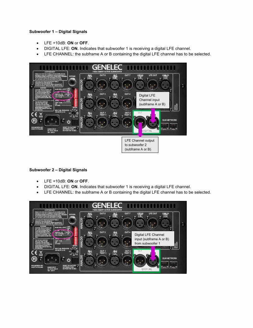
Subwoofer 1 – Digital Signals
• LFE +10dB: ON or OFF. • DIGITAL LFE: ON. Indicates that subwoofer 1 is receiving a digital LFE channel. • LFE CHANNEL: the subframe A or B containing the digital LFE channel has to be selected.
Subwoofer 2 – Digital Signals
• LFE +10dB: ON or OFF. • DIGITAL LFE: ON. Indicates that subwoofer 1 is receiving a digital LFE channel. • LFE CHANNEL: the subframe A or B containing the digital LFE channel has to be selected.
Digital LFE Channel input (subframe A or B)
LFE Channel output to subwoofer 2 (subframe A or B)
Digital LFE Channel input (subframe A or B) from subwoofer 1

Genelec Oy Olvitie 5 T +358 17 83 881 [email protected] FI-74100 Iisalmi F +358 17 81 2267 www.genelec.com Finland