application note cpx-ap-i with ethernet/ip; rockwell
TRANSCRIPT
100299
Application Note
CPX-AP-I with EtherNet/IP; Rockwell Systems and Others
How to best commission a CPX-AP-I system on EtherNet/IP. A focus will be on integration with Rockwell Logix systems, but much of the content is also applicable with any EtherNet/IP master.
CPX-AP-I-EP

Title ................................................................................ CPX-AP-I with EtherNet/IP; Rockwell Systems and Others
Version ............................................................................................................................................................. 1.30
Document no. .............................................................................................................................................. 100299
Original .................................................................................................................................................................en
Author ............................................................................................................................................................. Festo
Last saved ............................................................................................................................................ 24.06.2021
Copyright Notice This documentation is the intellectual property of Festo SE & Co. KG, which also has the exclusive copyright. Any modification of the content, duplication or reprinting of this documentation as well as distribution to third par-ties can only be made with the express consent of Festo SE & Co. KG.
Festo SE & Co KG reserves the right to make modifications to this document in whole or in part. All brand and product names are trademarks or registered trademarks of their respective owners.
Legal Notice Hardware, software, operating systems and drivers may only be used for the applications described and only in conjunction with components recommended by Festo SE & Co. KG.
Festo SE & Co. KG does not accept any liability for damages arising from the use of any incorrect or incomplete information contained in this documentation or any information missing therefrom.
Defects resulting from the improper handling of devices and modules are excluded from the warranty.
The data and information specified in this document should not be used for the implementation of safety func-tions relating to the protection of personnel and machinery.
No liability is accepted for claims for damages arising from a failure or functional defect. In other respects, the regulations with regard to liability from the terms and conditions of delivery, payment and use of software of Festo SE & Co. KG, which can be found at www.festo.com and can be supplied on request, shall apply.
All data contained in this document do not represent guaranteed specifications, particularly with regard to func-tionality, condition or quality, in the legal sense.
The information in this document serves only as basic information for the implementation of a specific, hypo-thetical application and is in no way intended as a substitute for the operating instructions of the respective manufacturers and the design and testing of the respective application by the user.
The operating instructions for Festo products can be found at www.festo.com/sp .
Users of this document (application note) must verify that all functions described here also work correctly in the application. By reading this document and adhering to the specifications contained therein, users are also solely responsible for their own application.
© (Festo SE & CO. KG, D-73726 Esslingen, 2021) Internet: http://www.festo.com
Components/Software used
Application Note – CPX-AP-I with EtherNet/IP; Rockwell Systems and Others – 1.30 Page 3 of 67
Table of contents
1 Components/Software used ....................................................................................................................... 5
2 Introduction ................................................................................................................................................ 6
3 Terminal View for AP Modules ................................................................................................................... 7
3.1.1 AP-I System Primary and Secondary Branches ............................................................................... 7 3.1.2 AP – Terminal and Parameters ....................................................................................................... 8 3.1.3 AP Terminal – Tool View .............................................................................................................. 10 3.1.4 AP Configuration – Stored Parameters ........................................................................................ 11 3.1.5 AP Configuration - Firmware......................................................................................................... 12 3.1.6 AP Configuration – Username/Password ..................................................................................... 12
4 EtherNet/IP View for Commissioning ....................................................................................................... 13
4.1.1 EtherNet/IP - Assembly Instances view for Exact and Fixed Size Instances .................................. 13 4.1.2 EtherNet/IP - EDS File .................................................................................................................. 15 4.1.3 EtherNet/IP - Rockwell L5X Project Export, Configuration, Status Assembly ............................... 15 4.1.4 EtherNet/IP – Large Forward Open Message (LFO) ...................................................................... 16
4.2 EtherNet/IP - Rockwell L5X Project Export Procedure ................................................................................ 17
4.2.1 Webserver Procedure ................................................................................................................... 17 4.2.2 Studio 5000 Procedure ................................................................................................................ 17 4.2.3 Transfer to the User Project ......................................................................................................... 18 4.2.4 Transferred Elements Description ................................................................................................ 23
4.3 EtherNet/IP – Insert Module using Nested Datatypes ............................................................................... 24
4.3.1 Export a new L5X Configuration ................................................................................................... 24 4.3.2 Edit User Defined Data Types (UDTs) ........................................................................................... 24 4.3.3 Overwrite Tags and UDTs before Importing into Working Project ................................................ 25 4.3.4 Complete Procedure – Check Program Rungs .............................................................................. 26 4.3.5 Edit, Save, and Download New Project ........................................................................................ 26
5 Festo Automation Suite (FAS) for Pre-Commissioning ............................................................................. 27
5.1 Festo Automation Suite CPX-AP-I Plug-In ver. 1.0.0.333 or greater .............................................. 27 5.2 FAS sample page with CPX-AP-I Configuration ............................................................................. 27 5.3 FAS sample page with CPX-AP-I Module Parameter Set-up .......................................................... 27 5.4 FAS sample page with CPX-AP-I Export to L5X ............................................................................. 28
6 System View for Diagnostics and Information ......................................................................................... 29
6.1.1 Diagnosis for Network and Communication ................................................................................. 29 6.1.2 Information .................................................................................................................................. 30 6.1.3 About ........................................................................................................................................... 30
7 Handling Diagnostic Events ..................................................................................................................... 31
7.1.1 Use Case - Reading Diagnostics via process data ........................................................................ 31 7.1.2 Use Case – Use Status and Diagnostic Objects to access diagnostics with Service Data ............. 32 7.1.3 Use Case – Get Latest Trace Data Entry example ......................................................................... 34 7.1.4 Use Case – Recover from Comm Errors ........................................................................................ 35
8 Handling Parameters with the CPX-AP System via the Parameter Object ............................................... 36
8.1.1 CPX-AP Parameter IDs and Instances; Use Case – Write to specific ID ........................................ 36 8.1.2 CPX-AP System Reading Parameter Object; Use Case – Read Parameters for use in HMI ............ 38 8.1.3 CPX-AP System Stored Parameters .............................................................................................. 43
9 IO-Link and ISDUs with the CPX-AP System via the IO-Link Object ........................................................ 44
9.1.1 CPX-AP IO-Link Module Basic Set-Up ........................................................................................... 44 9.1.2 CPX-AP IO-Link Module Process Data ........................................................................................... 46 9.1.3 CPX-AP ISDU Access with Explicit Message for Parameterizing .................................................... 46 9.1.3.1 CPX-AP ISDU Access – MSG Instruction Read Data Example with Explicit Message ..................... 50 9.1.3.2 CPX-AP ISDU Access – MSG Instruction Write Data Example with Explicit Message ..................... 52 9.1.3.3 CPX-AP ISDU Access – MSG Instruction Read Vendor ID Example with Explicit Message ............. 53
Components/Software used
Page 4 of 67 Application Note – CPX-AP-I with EtherNet/IP; Rockwell Systems and Others – 1.30
10 Festo IO-Link Tool ..................................................................................................................................... 54
10.1.1 Getting Started ............................................................................................................................ 54 10.1.2 Sequence of Commissioning ........................................................................................................ 54
11 Modbus TCP View ..................................................................................................................................... 62
11.1 Modbus TCP Overview for the CPX-AP System .......................................................................................... 62
11.2 Modbus TCP Holding Register View ........................................................................................................... 64
11.3 Modbus TCP Input Register View ............................................................................................................... 66

Components/Software used
Application Note – CPX-AP-I with EtherNet/IP; Rockwell Systems and Others – 1.30 Page 5 of 67
1 Components/Software used
Type/Name Version Software/Firmware Date of manufacture
CPX-AP-I-EP-M12 Rev1.3.1 Released May 26, 2021
CPX-AP-I-4DI4DO-M12-5P Rev1.46.4
CPX-AP-I-8DI-M8-3P Rev1.46.4
VAEM-L1-S-24-AP Rev1.46.4
CPX-AP-I-4IOL-M12 Rev1.4.9
CPX-AP-I-4AI-U-I-RTD-M12 Rev0.5.9
Rockwell Studio 5K V30, V31,V32
Rockwell 1769-L30ERMS PLC V32
Google Chrome
Festo Automation Suite CPX-AP plug-in 1.0.0.333
Table 1.1: 1 Components/Software used
Revision History Modified by Date
Rev 0 – initial document fpl May 2019
- Parameter instance added Fpl July 2019
- Password screens added fpl Sept. 2019
Rev 1 - Updates to export function and clean-up fpl Dec. 2019
Rev 2 – Add IO-Link operation with CIP IOL Object fpl Feb. 2020
Rev 3 – Add IO-Link SW tool, Stored Param., Large Forward Open, Nested UDT, Module Insert, Modbus, FAS, minor enhancements
fpl June 2021
Introduction
Page 6 of 67 Application Note – CPX-AP-I with EtherNet/IP; Rockwell Systems and Others – 1.30
2 Introduction
The CPX-AP-I-EP is an EtherNet/IP adapter that connects Festo CPX-AP-I modules to EtherNet/IP. This note will cover web server based features of the CPX-AP-I-EP system to assist in configuration of the EtherNet/IP adapter with Rockwell and other systems.
Festo provides documentation in a user manual to configure and use the AP-I system. This application note is intended to provide details and hints for additional features possible when using a ControLogix or CompactLogix PLC from Rockwell over EtherNet/IP, or any other EtherNet/IP master system. Therefore, it is a prerequisite to this note that the user must use the Festo documentation of the AP-I system modules for valves, I/O, and Ether-Net/IP. This is needed to become especially familiar with the following:
• Use of the Rotary switches of the CPX-AP-I-EP module • Understanding of the LEDs of the system • Understanding of the power, communication, and network cables used for the system • Understanding power requirements, power distribution, and grounding of the system • Understanding the use of module parameters

Terminal View for AP Modules
Application Note – CPX-AP-I with EtherNet/IP; Rockwell Systems and Others – 1.30 Page 7 of 67
3 Terminal View for AP Modules
3.1.1 AP-I System Primary and Secondary Branches
The AP-I system starts with a network adapter that has 2 branches for distributing I/O.
The CPX-AP-I-EP adapter is always slot 1 of the AP system. The left AP-I connector is the primary branch. All modules connected to the primary branch consume the next available slot numbers, in order of connection. The leftmost AP-I connector is the incoming branch (topmost for pneumatic), the rightmost is the outgoing branch.
Example of primary branch, modules in slots 1, 2, and 3.
Primary AP-I branch
Slot 1 Slot 2 Slot 3
CPX-AP-I-EP-M12 CPX-AP-I-4DI4DO-M12-5P
VAEM-L1-S-24-AP

Terminal View for AP Modules
Page 8 of 67 Application Note – CPX-AP-I with EtherNet/IP; Rockwell Systems and Others – 1.30
The right AP-I connector is the Secondary branch of the AP-I system. Modules connected to the Secondary branch start consuming slot numbers after the last slot number of the Primary branch. The above example shows the completed test system with all 4 slots consumed.
3.1.2 AP – Terminal and Parameters
The CPX-AP…EP webserver shows the connected configuration of the modules, slots 1 to 6 in this example. The module description, code, FW version, serial numbers, and product key are displayed. The EP p/k is not dis-played since this is the password for the web access. This is the 11 alpha/numeric code found on the adapter.
Slot 1 Slot 2 Slot 3
CPX-AP-I-EP-M12 CPX-AP-I-4DI4DO-M12-5P
VAEM-L1-S-24-AP
Slot 4
CPX-AP-I-8DI
-M8-3P

Terminal View for AP Modules
Application Note – CPX-AP-I with EtherNet/IP; Rockwell Systems and Others – 1.30 Page 9 of 67
When selecting a module, a Sign-in access is required for the first time in a session. The credentials are:
User: admin
Password: the product key of the EP adapter found on label
Each module can be configured by clicking on it. For example, slot 1 is the EtherNet/IP adapter. One click on the module opens the parameter selection list for the module.
Slot 1. The CPX-AP-I-EP module has configuration parameters for IP address maintenance and supply voltage diagnostics.
NOTE: Each parameter has instance numbers for the CIP Parameter Object and AP ID instance. This facilitates easy look-up for module parameters. Every module has this list. See Parameter Object section of App Note.
Slot 2 example. The CPX-AP-I-4DI4DO-M12-5P has configuration parameters for debounce time, and fail safe state for outputs (default off or hold last state).

Terminal View for AP Modules
Page 10 of 67 Application Note – CPX-AP-I with EtherNet/IP; Rockwell Systems and Others – 1.30
Some modules, such as the 4 channel analog input may have an extensive list of parameters. The 4AI module has 52 parameters for configuring the 4 analog channels.
3.1.3 AP Terminal – Tool View
As of FW version 1.2.7, the AP Terminal page has a Tool View which allows the user to change the page with a different focus. The options are as follows:
Select the “wrench” icon to change the focus to display process data, supply voltage, or cable info.
The Information page is the default page. In addition to the module name, code, FW version, serial number, product key, and diagnostic status, the is an identify slide. Select “Identify” to flash the MD led of the module to locate it in a system.

Terminal View for AP Modules
Application Note – CPX-AP-I with EtherNet/IP; Rockwell Systems and Others – 1.30 Page 11 of 67
The Process Data focus shows the actual I/O status, dynamically, with an update rate of about 1 second.
The Supply Voltage focus shows the dynamic value of the various voltage supplies of each module.
The Cable Information focus shows the cable lengths detected by the system.
The information in the various focus views provide useful troubleshooting information during commissioning and routine maintenance.
3.1.4 AP Configuration – Stored Parameters
The CPX-AP system for EtherNet/IP and Modbus can store parameters internally in FW 1.2.7 or later. This is es-pecially useful for the following users:
• Modbus TCP users where no standard parameter setting process from a controller exists.
Terminal View for AP Modules
Page 12 of 67 Application Note – CPX-AP-I with EtherNet/IP; Rockwell Systems and Others – 1.30
• EtherNet/IP users where there is no ability to store parameters in the controller and push into the CPX-AP system via the Forward Open message. This may include some robot controllers, PC control, or other controllers.
Go to section 8.1.3 for more information on Stored Parameters.
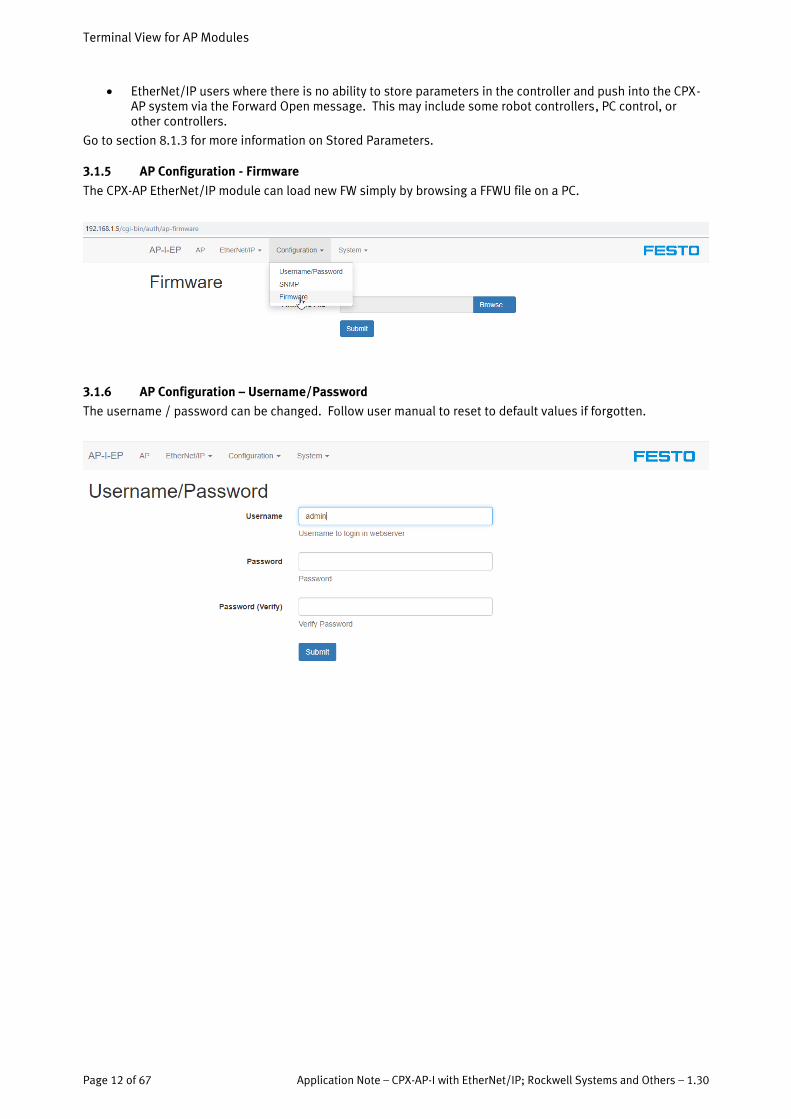
3.1.5 AP Configuration - Firmware
The CPX-AP EtherNet/IP module can load new FW simply by browsing a FFWU file on a PC.
3.1.6 AP Configuration – Username/Password
The username / password can be changed. Follow user manual to reset to default values if forgotten.

EtherNet/IP View for Commissioning
Application Note – CPX-AP-I with EtherNet/IP; Rockwell Systems and Others – 1.30 Page 13 of 67
4 EtherNet/IP View for Commissioning
4.1.1 EtherNet/IP - Assembly Instances view for Exact and Fixed Size Instances
The CPX-AP-I-EP has numerous Assembly Instances for configuration. The reason is to get the best commission-ing experience based on the controller type of the user, and the types of modules connected to the EtherNet/IP adapter.
Exact size instances (100 – 105 / 131 – 133):
• Use this to optimize the memory consumption of your controller. The Assembly view page shows the I/O size of the different datatypes of the I/O Produce and Consume values. These values can be placed directly in your commissioning software.
• Select the datatype that best matches the modules in your AP-I system. For example, mostly digital modules may best fit the SINT datatype. Mostly analog modules will fit the INT datatype. More data intensive modules like IO-Link may be best supported by the DINT datatype. DINT may also have other benefits when manipulating data within a Rockwell controller.
o Data will always be padded in a datatype so a new module will start at the beginning of the next datatype in an array.
Fixed Size instances (110 – 125 / 134 – 139):
• Use this to pre-allocate memory space in your controller so additional modules can be added at any time. Select the appropriate fixed size for your application. You must at least exceed the I/O size being produced or consumed. The physical configuration cannot exceed the instance chosen.
• The input and output sizes do not have to be equal. • Instances exist to include diagnostics too. See description above for diagnostics • Choose the appropriate datatype instance to match the modules chosen. In this case SINT and DINT are
available.
Configuration Instance (140):
• Always use 140. This will be populated if L5X export is used and the configuration assembly is enabled.
Status and Diagnostic Instances (129 – 130):
• Use these to include status and diagnostic information from the AP-I system. o Instances 129 and 130 are separate instances that can be used specifically for Status Input of a
generic ethernet set-up ▪ Instance 129 includes both global and module status and diagnostics ▪ Instance 130 includes global status and diagnostics only
o Exact and Fixed instances with Status and Diagnostics place the Global only information at the top of the input table.
o Use 254 for Status Output • The Status and Diagnostic instances for both global and module data is structured as follows:
EtherNet/IP View for Commissioning
Page 14 of 67 Application Note – CPX-AP-I with EtherNet/IP; Rockwell Systems and Others – 1.30
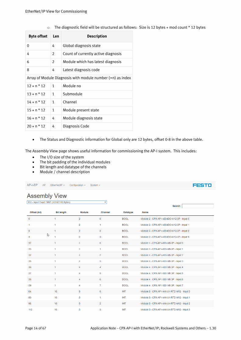
o The diagnostic field will be structured as follows: Size is 12 bytes + mod count * 12 bytes
Byte offset Len Description
0 4 Global diagnosis state
4 2 Count of currently active diagnosis
6 2 Module which has latest diagnosis
8 4 Latest diagnosis code
Array of Module Diagnosis with module number (=n) as index
12 + n * 12 1 Module no
13 + n * 12 1 Submodule
14 + n * 12 1 Channel
15 + n * 12 1 Module present state
16 + n * 12 4 Module diagnosis state
20 + n * 12 4 Diagnosis Code
• The Status and Diagnostic information for Global only are 12 bytes, offset 0-8 in the above table.
The Assembly View page shows useful information for commissioning the AP-I system. This includes:
• The I/O size of the system • The bit padding of the individual modules • Bit length and datatype of the channels • Module / channel description
EtherNet/IP View for Commissioning
Application Note – CPX-AP-I with EtherNet/IP; Rockwell Systems and Others – 1.30 Page 15 of 67
4.1.2 EtherNet/IP - EDS File
Select EDS file to download the EDS file to your PC. Install this in your communication commissioning software, ie: EDS Hardware Installation Tool, so the device identity is recognized. This device provides a static EDS file.
4.1.3 EtherNet/IP - Rockwell L5X Project Export, Configuration, Status Assembly
The CPX-AP-I has a Web Server export function to create an L5X project based on the current configuration and parameter settings. This function has multiple benefits for the user with Rockwell Automation Studio 5000:
• A Generic Ethernet Module template can be generated with the exact I/O size, configuration size, con-figuration values, and assembly instances for the AP system. No user mistakes.
• Optional Status and Diagnostic instance and size is generated automatically. • Configuration data gets stored in the user project, and is downloaded upon connection with EIP. This
facilitates disaster recovery situations. • User Defined Datatypes (UDTs) are generated with meaningful Tag Names, data types, and descrip-
tions. Clear and simple programming, no need for datatype conversions. • Programming instructions to transfer data from UDT to generic module tag name, and support Large
Forward Open if needed. No need for extra programming.
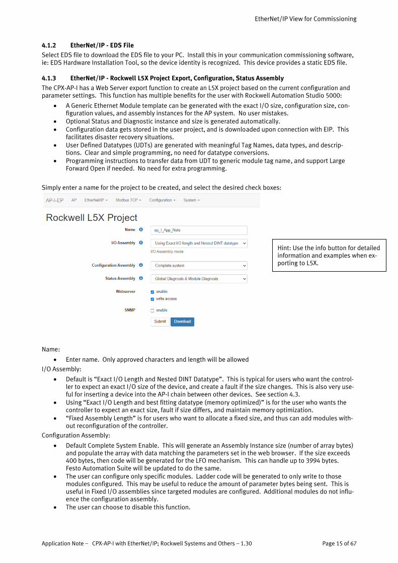
Simply enter a name for the project to be created, and select the desired check boxes:
Name:
• Enter name. Only approved characters and length will be allowed
I/O Assembly:
• Default is “Exact I/O Length and Nested DINT Datatype”. This is typical for users who want the control-ler to expect an exact I/O size of the device, and create a fault if the size changes. This is also very use-ful for inserting a device into the AP-I chain between other devices. See section 4.3.
• Using “Exact I/O Length and best fitting datatype (memory optimized)” is for the user who wants the controller to expect an exact size, fault if size differs, and maintain memory optimization.
• “Fixed Assembly Length” is for users who want to allocate a fixed size, and thus can add modules with-out reconfiguration of the controller.
Configuration Assembly:
• Default Complete System Enable. This will generate an Assembly Instance size (number of array bytes) and populate the array with data matching the parameters set in the web browser. If the size exceeds 400 bytes, then code will be generated for the LFO mechanism. This can handle up to 3994 bytes. Festo Automation Suite will be updated to do the same.
• The user can configure only specific modules. Ladder code will be generated to only write to those modules configured. This may be useful to reduce the amount of parameter bytes being sent. This is useful in Fixed I/O assemblies since targeted modules are configured. Additional modules do not influ-ence the configuration assembly.
• The user can choose to disable this function.
Hint: Use the info button for detailed information and examples when ex-porting to L5X.

EtherNet/IP View for Commissioning
Page 16 of 67 Application Note – CPX-AP-I with EtherNet/IP; Rockwell Systems and Others – 1.30
Status Assembly:
• Default is Global and Module Status. A Generic Ethernet Module with Status Inputs will be generated. There will be 12 bytes global plus 12 bytes per module allocated for Status and Diagnostics. This in-cludes the EtherNet/IP adapter as a module.
• User selects Global Only status. A Generic Ethernet module with Status Inputs will be generated. There will be 12 bytes of data allocated for Status and Diagnostic.
• User selects no Status. A Generic Ethernet Module will be generated without Status inputs. • Refer to section 4.1.1 under Status and Diagnostic Instances for the structure of the information.
Webserver:
• Default enable. The user can change this parameter so the webserver is disabled, if they wish to have no webserver access.
• Write Access, default enabled. The user can disable write access. This is useful if the user wishes to prevent someone from changing the parameters of the system, but still wants viewing access.
o If these are disabled when using the exported L5X project, each time the controller connects to the system, the webserver will not be enabled or have no write access while the machine is running. All of the exported parameter settings will be used.
SNMP (simple network management protocol):
• Default is disabled. SNMP is useful for troubleshooting purposes of ethernet networks. MIB (manage-ment information base) browsers use SNMP for providing access to diagnostic network info.
• SNMP can also be an avenue for security risk. Ethernet parameters can be changed with this protocol. Therefore the user can disable this via the web browser.
To reverse these, the user can edit the project Config tag name in Studio 5000 Logix specific to the web server access, webserver enable, or SNMP enable. One, 1, is enable; 0 is disable.
4.1.4 EtherNet/IP – Large Forward Open Message (LFO)
The CPX-AP system can have a parameter size in excess of 400 bytes, which is the limit for the standard Forward Open message of EtherNet/IP. The Forward Open message (LFO) is the mechanism where parameter values are pushed to the controller from the device upon start-up.
If the configuration size is larger than 400 bytes, the CPX-AP system uses a programmed method supporting the LFO mechanism. The ladder code for this is automatically generated when doing the L5X export. The LFO max size is 3994 bytes.
More information can be found in section 4.2.3.
EtherNet/IP View for Commissioning
Application Note – CPX-AP-I with EtherNet/IP; Rockwell Systems and Others – 1.30 Page 17 of 67
4.2 EtherNet/IP - Rockwell L5X Project Export Procedure
The procedure to export the L5X file for a CPX-AP-I-EP system has several simple steps. There are several steps required from the webserver, and within Studio 5000.
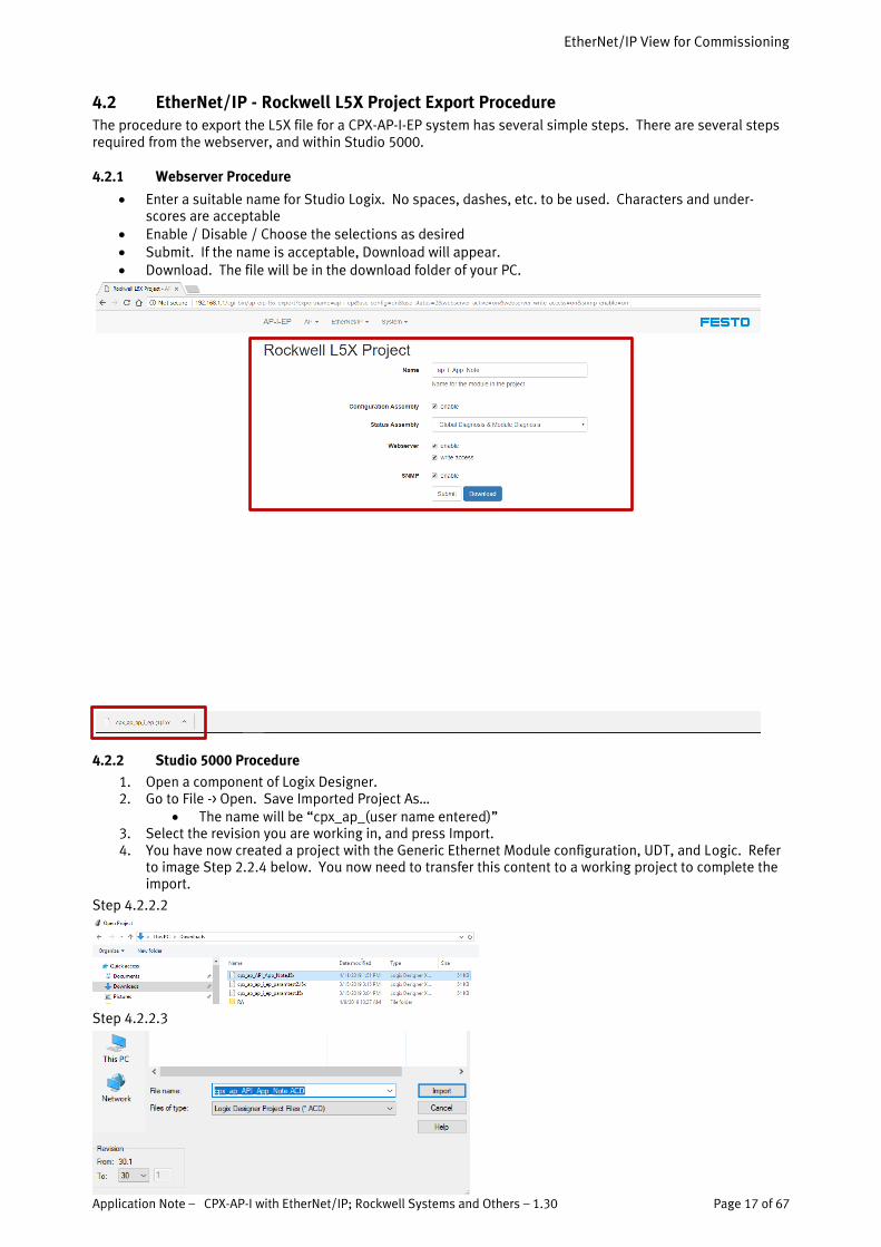
4.2.1 Webserver Procedure
• Enter a suitable name for Studio Logix. No spaces, dashes, etc. to be used. Characters and under-scores are acceptable
• Enable / Disable / Choose the selections as desired • Submit. If the name is acceptable, Download will appear. • Download. The file will be in the download folder of your PC.
4.2.2 Studio 5000 Procedure
1. Open a component of Logix Designer. 2. Go to File -> Open. Save Imported Project As…
• The name will be “cpx_ap_(user name entered)” 3. Select the revision you are working in, and press Import. 4. You have now created a project with the Generic Ethernet Module configuration, UDT, and Logic. Refer
to image Step 2.2.4 below. You now need to transfer this content to a working project to complete the import.
Step 4.2.2.2
Step 4.2.2.3

EtherNet/IP View for Commissioning
Page 18 of 67 Application Note – CPX-AP-I with EtherNet/IP; Rockwell Systems and Others – 1.30
Step 4.2.2.4
4.2.3 Transfer to the User Project
1. Right click on the Generic Ethernet Module in the created project and copy. Paste this into the user project by Right Click on Ethernet and select paste. Be sure the IP address does not conflict with an ex-isting IP address.
Step 4.2.3.1
Copy from Generated project: Paste to User Project:
EtherNet/IP View for Commissioning
Application Note – CPX-AP-I with EtherNet/IP; Rockwell Systems and Others – 1.30 Page 19 of 67
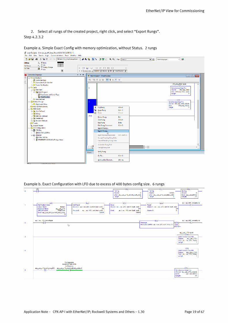
2. Select all rungs of the created project, right click, and select “Export Rungs”.
Step 4.2.3.2
Example a. Simple Exact Config with memory optimization, without Status. 2 rungs
Example b. Exact Configuration with LFO due to excess of 400 bytes config size. 6 rungs
EtherNet/IP View for Commissioning
Page 20 of 67 Application Note – CPX-AP-I with EtherNet/IP; Rockwell Systems and Others – 1.30
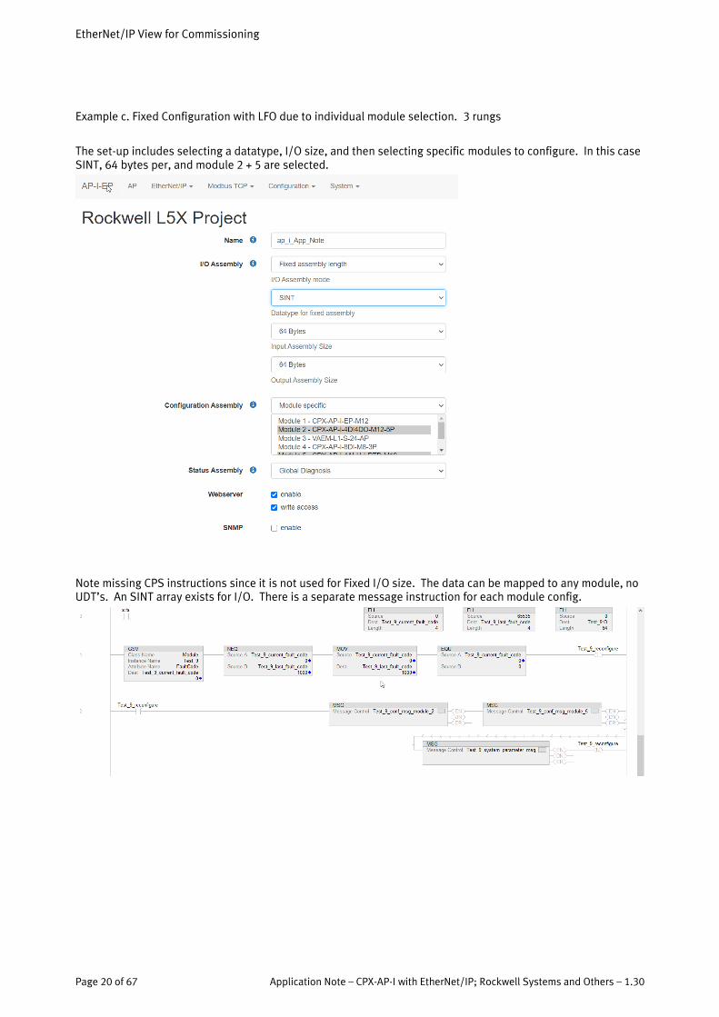
Example c. Fixed Configuration with LFO due to individual module selection. 3 rungs
The set-up includes selecting a datatype, I/O size, and then selecting specific modules to configure. In this case SINT, 64 bytes per, and module 2 + 5 are selected.
Note missing CPS instructions since it is not used for Fixed I/O size. The data can be mapped to any module, no UDT’s. An SINT array exists for I/O. There is a separate message instruction for each module config.

EtherNet/IP View for Commissioning
Application Note – CPX-AP-I with EtherNet/IP; Rockwell Systems and Others – 1.30 Page 21 of 67
3. This will create a file name “Rungs0toN_from_MainRoutine_(user name entered).L5X”. Select Export.
Step 4.2.3.3
4. Import the file from the previous step into the user project. Right click on any rung, preferably in the Main Routine, and select Import Rungs. A pop-up will confirm the import of the rungs, plus datatypes and other components. Select OK.
Step 4.2.3.4
NOTE: DO NOT COPY AND PASTE UDTs. IT MAY APPEAR TO WORK, BUT HIDDEN MEMBERS OF THE DATA-STRUCTURE WILL NOT TRANSFER OVER, AND THE WRONG SIZE UDT WILL BE INSTALLED.

EtherNet/IP View for Commissioning
Page 22 of 67 Application Note – CPX-AP-I with EtherNet/IP; Rockwell Systems and Others – 1.30
5. The L5X imported into the user project provides Tag names with custom datatypes (UDTs), and the logic to copy this data to the raw I/O instances of the Generic Ethernet Module set-up. Move the logic as nec-essary to suit your needs.
Step 4.2.3.5

EtherNet/IP View for Commissioning
Application Note – CPX-AP-I with EtherNet/IP; Rockwell Systems and Others – 1.30 Page 23 of 67
4.2.4 Transferred Elements Description
The elements generated and transferred by the L5X includes:
1. A set of I/O tag names of the following: i. “User name entered”_Inputs
ii. “User name entered”_Outputs iii. “User name entered”_Status (if selected) iv. The datatypes of these names are a user defined datatype (UDT) which has a custom
structure suited for the module types installed on the AP-I system. 1. Solenoids and digital I/O will be Boolean 2. Analog will be Integer 3. Specialty I/O can be SINT, DINT or other based on necessity
v. The elements will automatically be annotated in the Description Field to facilitate eas-ier programming by the user.
Image 4.2.4.1, example of input and output tags with optimized, exact, custom UDT descriptions
Image 4.2.4.2; Shows benefit of UDT. Transition from digital to analog device shows the appropriate datatype. No conversions necessary when programming to UDT.
2. A set of rungs in ladder logic to do a Synchronous Copy of data from the custom tag names to the raw I/O Assembly Instances of the Generic Ethernet Module. It is good practice to keep the CPS instruction for the inputs or status near the top of the user logic, and the CPS instruction for the Outputs should be near the bottom of the logic where setting outputs occurs.
Image 4.2.4.3

EtherNet/IP View for Commissioning
Page 24 of 67 Application Note – CPX-AP-I with EtherNet/IP; Rockwell Systems and Others – 1.30
4.3 EtherNet/IP – Insert Module using Nested Datatypes
The procedure to insert a module into the CPX-AP line topology can be easily done if a project was created with Exact Size plus Nested Datatypes. This would be with FW ver 1.3.1 or higher of the CPX-AP-x-EP module. The physical assignment of module numbers are not changed, but a simple modification of the UDT’s generated by the L5X export will allow the user to insert a module, and not change the Tag Names of the modules already used.
PROs:
• Insert a module anywhere in the system. • This does not disrupt the tag names already existing. No need to edit tags or rungs of code.
CONs:
• Webserver Slot number does not align with programmed module numbers • Descriptions changed in the original project will be overwritten
4.3.1 Export a new L5X Configuration
• You must keep the name exactly the same as in the original project • Use the default I/O Assembly “Exact I/O Length and Nested datatype”. • Configuration and Status Assembly should be the same as in the original project.
4.3.2 Edit User Defined Data Types (UDTs)
Follow the same procedure as in section 4.2 to export an L5X file, but make the following changes to the UDTs generated in the exported file:
• Edit the data types by double clicking on the following data types under Data Types -> User-Defined (This is under Assets -> Data Types -> User Defined in versions of Logix above V30).
o dt_name_inputs o dt_name_outputs o dt_name_status
• In this example, module_2 is a 4DI4DO module that was inserted into a CPX-AP-I system that was previ-ously running in a project.
EtherNet/IP View for Commissioning
Application Note – CPX-AP-I with EtherNet/IP; Rockwell Systems and Others – 1.30 Page 25 of 67
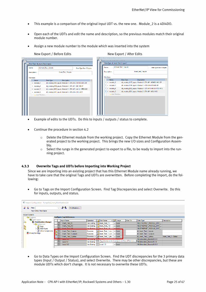
• This example is a comparison of the original input UDT vs. the new one. Module_2 is a 4DI4DO.
• Open each of the UDTs and edit the name and description, so the previous modules match their original module number.
• Assign a new module number to the module which was inserted into the system New Export / Before Edits New Export / After Edits
• Example of edits to the UDTs. Do this to inputs / outputs / status to complete.
• Continue the procedure in section 4.2
o Delete the Ethernet module from the working project. Copy the Ethernet Module from the gen-erated project to the working project. This brings the new I/O sizes and Configuration Assem-bly.
o Select the rungs in the generated project to export to a file, to be ready to import into the run-ning project.
4.3.3 Overwrite Tags and UDTs before Importing into Working Project
Since we are importing into an existing project that has this Ethernet Module name already running, we have to take care that the original Tags and UDTs are overwritten. Before completing the import, do the fol-lowing:
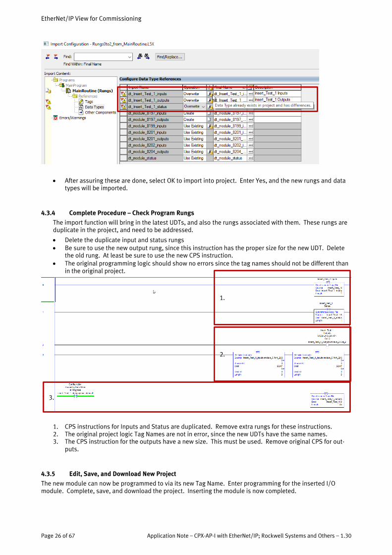
• Go to Tags on the Import Configuration Screen. Find Tag Discrepancies and select Overwrite. Do this for inputs, outputs, and status.
• Go to Data Types on the Import Configuration Screen. Find the UDT discrepancies for the 3 primary data types (Input / Output / Status), and select Overwrite. There may be other discrepancies, but these are module UDTs which don’t change. It is not necessary to overwrite these UDTs.
EtherNet/IP View for Commissioning
Page 26 of 67 Application Note – CPX-AP-I with EtherNet/IP; Rockwell Systems and Others – 1.30
• After assuring these are done, select OK to import into project. Enter Yes, and the new rungs and data types will be imported.
4.3.4 Complete Procedure – Check Program Rungs
The import function will bring in the latest UDTs, and also the rungs associated with them. These rungs are duplicate in the project, and need to be addressed.
• Delete the duplicate input and status rungs • Be sure to use the new output rung, since this instruction has the proper size for the new UDT. Delete
the old rung. At least be sure to use the new CPS instruction. • The original programming logic should show no errors since the tag names should not be different than
in the original project.
1. CPS instructions for Inputs and Status are duplicated. Remove extra rungs for these instructions. 2. The original project logic Tag Names are not in error, since the new UDTs have the same names. 3. The CPS instruction for the outputs have a new size. This must be used. Remove original CPS for out-
puts.
4.3.5 Edit, Save, and Download New Project
The new module can now be programmed to via its new Tag Name. Enter programming for the inserted I/O module. Complete, save, and download the project. Inserting the module is now completed.
2.
1.
3.
Festo Automation Suite (FAS) for Pre-Commissioning
Application Note – CPX-AP-I with EtherNet/IP; Rockwell Systems and Others – 1.30 Page 27 of 67
5 Festo Automation Suite (FAS) for Pre-Commissioning
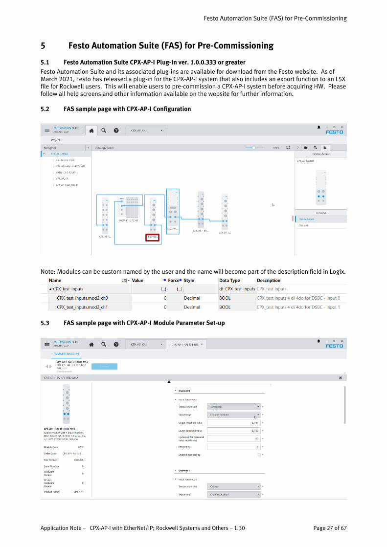
5.1 Festo Automation Suite CPX-AP-I Plug-In ver. 1.0.0.333 or greater
Festo Automation Suite and its associated plug-ins are available for download from the Festo website. As of March 2021, Festo has released a plug-in for the CPX-AP-I system that also includes an export function to an L5X file for Rockwell users. This will enable users to pre-commission a CPX-AP-I system before acquiring HW. Please follow all help screens and other information available on the website for further information.
5.2 FAS sample page with CPX-AP-I Configuration
Note: Modules can be custom named by the user and the name will become part of the description field in Logix.
5.3 FAS sample page with CPX-AP-I Module Parameter Set-up
Festo Automation Suite (FAS) for Pre-Commissioning
Page 28 of 67 Application Note – CPX-AP-I with EtherNet/IP; Rockwell Systems and Others – 1.30
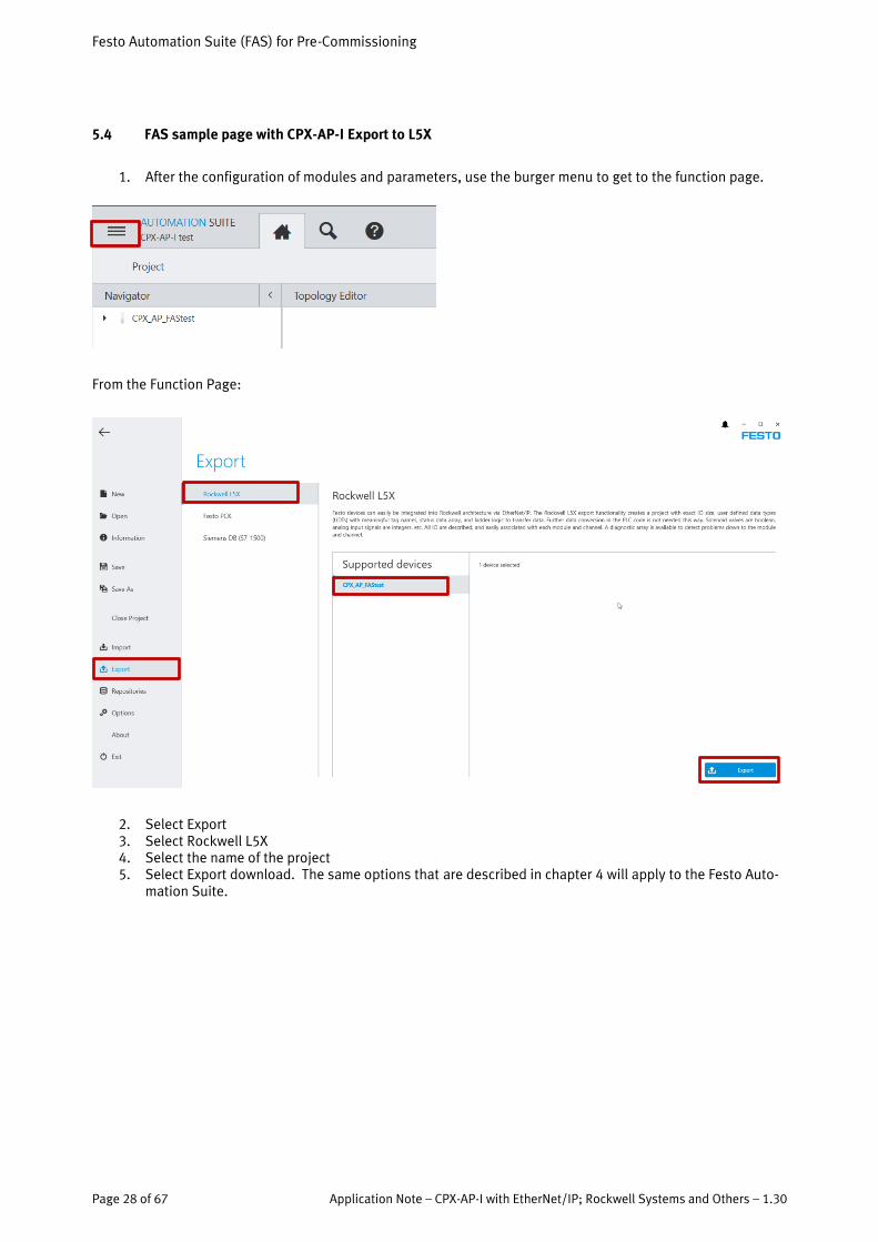
5.4 FAS sample page with CPX-AP-I Export to L5X
1. After the configuration of modules and parameters, use the burger menu to get to the function page.
From the Function Page:
2. Select Export 3. Select Rockwell L5X 4. Select the name of the project 5. Select Export download. The same options that are described in chapter 4 will apply to the Festo Auto-
mation Suite.

System View for Diagnostics and Information
Application Note – CPX-AP-I with EtherNet/IP; Rockwell Systems and Others – 1.30 Page 29 of 67
6 System View for Diagnostics and Information
6.1.1 Diagnosis for Network and Communication
The diagnosis page provides network information and diagnostics. This can be used in addition to the user manual description of network LEDs to solve communication and network problems.
Information useful for R&D can be found on the Diagnosis page:
The Outputs lost power
The Outputs regained power about 57 seconds later. Grey “X” means the problem was resolved.
System View for Diagnostics and Information
Page 30 of 67 Application Note – CPX-AP-I with EtherNet/IP; Rockwell Systems and Others – 1.30
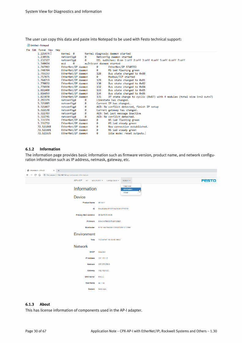
The user can copy this data and paste into Notepad to be used with Festo technical support:
6.1.2 Information
The information page provides basic information such as firmware version, product name, and network configu-ration information such as IP address, netmask, gateway, etc.
6.1.3 About
This has license information of components used in the AP-I adapter.

Handling Diagnostic Events
Application Note – CPX-AP-I with EtherNet/IP; Rockwell Systems and Others – 1.30 Page 31 of 67
7 Handling Diagnostic Events
7.1.1 Use Case - Reading Diagnostics via process data
The easiest and most comprehensive method for reading diagnostics is to use Assembly Instance 129 which in-cludes Global and Module Diagnostics. By selecting this in the L5X export, the system will generate a UDT for status of the CPX-AP system.
The configuration will include a status connection, and an array of bytes suitable for the amount of diagnostic data. A UDT and logic is also generated for a proper data-structure and logic to pass the data to the structure. This enables intuitive mapping of the diagnostic data to Logix.
The data-structure below contains an example of a diagnostic event, lost output power.
In this example:
• The top group is the Global data. The latest code reported is 0x0201_0106. In the manual, this is an error with PL24vdc.
• Each other group is specific for a module, with the lowest module number on top. Only mod-ules with an output report an error, others are error free. Note state=5 means voltage prob-lem, but also communicating OK. See diagnostic bit table below.
NOTE: With Assembly Instance 130, and Fixed Assembly Instances with Global status, only the top group is avail-able. This is to limit the amount of PLC data.

Handling Diagnostic Events
Page 32 of 67 Application Note – CPX-AP-I with EtherNet/IP; Rockwell Systems and Others – 1.30
If bit is set at least one diagnosis of this category is available.
Bit Description Bit Description
0 Device available (Communication ok)
11 Software
1 Current 12 Maintenance
2 Voltage 13 Misc
3 Temperature 14 reserved
4 reserved 15 reserved
5 Movement 16 External Device
6 Configuration / Parameter
17 Security
7 Monitoring 18 Encoder
8 Communication 19-31 reserved
9 Safety
10 Internal Hardware
7.1.2 Use Case – Use Status and Diagnostic Objects to access diagnostics with Service Data
Diagnostics are always available, even without access from process data. The Status and Diagnostic Object can access diagnostic information with a n explicit message. This is optimally used in combination with Global diag-nostics only. Therefore, the process data for diagnostics are fixed at 12 bytes, and further detailed data can be read via explicit message.
Status and Diagnostic Object Class = 0x65. Get the last active diagnosis per module.
Attribute Ac-cess
Name Type Description Value
Class Attributes
1 Get Revision UINT Revision of the object 1
2 Get Max instances UINT Max instances of the CIP ob-ject
Module count of AP-System
3 Get Num instances UINT Num instances of the CIP ob-ject currently created
Modulecount of AP-System
6 Get Max Class At-tribute
UINT 9
7 Get Max Instance Attribute
UINT 4 (Diagnostic code)
8 Get Global Diagno-sis state
UDINT see Global Diagnosis State
9 Get Bus status USINT
Instances
Handling Diagnostic Events
Application Note – CPX-AP-I with EtherNet/IP; Rockwell Systems and Others – 1.30 Page 33 of 67
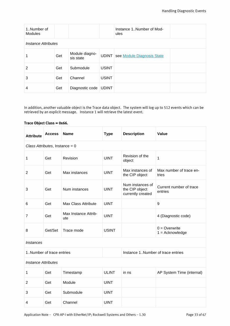
1..Number of Modules
Instance 1..Number of Mod-ules
Instance Attributes
1 Get Module diagno-sis state
UDINT see Module Diagnosis State
2 Get Submodule USINT
3 Get Channel USINT
4 Get Diagnostic code UDINT
In addition, another valuable object is the Trace data object. The system will log up to 512 events which can be retrieved by an explicit message. Instance 1 will retrieve the latest event.
Trace Object Class = 0x66.
Attribute
Access Name Type Description Value
Class Attributes, Instance = 0
1 Get Revision UINT Revision of the object
1
2 Get Max instances UINT Max instances of the CIP object
Max number of trace en-tries
3 Get Num instances UINT Num instances of the CIP object currently created
Current number of trace entries
6 Get Max Class Attribute UINT 9
7 Get Max Instance Attrib-ute
UINT 4 (Diagnostic code)
8 Get/Set Trace mode USINT 0 = Overwrite 1 = Acknowledge
Instances
1..Number of trace entries Instance 1..Number of trace entries
Instance Attributes
1 Get Timestamp ULINT in ns AP System Time (internal)
2 Get Module UINT
3 Get Submodule UINT
4 Get Channel UINT

Handling Diagnostic Events
Page 34 of 67 Application Note – CPX-AP-I with EtherNet/IP; Rockwell Systems and Others – 1.30
5 Get Diagnostic code UDINT
6 Get Severity USINT
1 = information 2 = maintenance required 4 = warning 8 = error
7 Get Type USINT
0 = inform 1 = raise
2 = resolve 3 = wait for acknowledge
8 Get Acked USINT true / false
By using other CIP services, all attributes of one diagnostic trace can be accessed at once by the Get Member service 0x18.
Service Name Description
0x0e Get Attribute Sin-gle
0x18 Get Member Get all attributes of one diag trace entry
0x32 Acknowledge trace entry
The Data-structure for the response is as follows:
Item Datatype
Timestamp ULINT
Module UINT
Submodule UINT
Channel UINT
Diagnostic code UDINT
Severity USINT
Type USINT
Acked USINT
7.1.3 Use Case – Get Latest Trace Data Entry example
The following ladder code example shows how to set-up the MSG instruction and array for the Trace data Get Member service. Instance 1 is the latest trace entry.
Service Class Instance
0x18 0x66 1..Number of trace entries
Get all attributes of 1 instance

Handling Diagnostic Events
Application Note – CPX-AP-I with EtherNet/IP; Rockwell Systems and Others – 1.30 Page 35 of 67
7.1.4 Use Case – Recover from Comm Errors
Some errors do not recover automatically. This is true for a link error in the AP-I bus. This is typically indicated by an error code 0x0801_0127. Also, global status bit 8 will be on indicating communication error. To recover from this error, recycle power will work. It is also possible to recycle the connection from the PLC.
This shows the global diagnostic field where bit 8 is on for the status, and the lost link diag code is present.
The following 2 rungs can recover from this via the PLC logic. Triggering the open contact will inhibit the PLC ethernet connection to the CPX-AP ethernet adapter. Once the physical connection is restored, removing the trigger will allow the connection to restore. NOTE: inhibiting the connection will turn off all I/O.

Handling Parameters with the CPX-AP System via the Parameter Object
Page 36 of 67 Application Note – CPX-AP-I with EtherNet/IP; Rockwell Systems and Others – 1.30
8 Handling Parameters with the CPX-AP System via the Parameter Object
8.1.1 CPX-AP Parameter IDs and Instances; Use Case – Write to specific ID
Parameter IDs are common IDs among the system modules. They can be read or written to via EtherNet/IP. A partial list of parameters can be found in the user manual. The webserver lists the ID in parameter order num-ber, from the first parameter of the first module (the EtherNet/IP adapter) to the last parameter of the last mod-ule.
In the above example, we can see the following:
• There are 15 parameters based on the last parameter of the last module • A common parameter ID is 20022. This is universal among modules for monitoring load supply • Another common parameter ID is 20014 for Input Debounce Time. • Each module has 1 instance of every parameter, instance 0.
Handling Parameters with the CPX-AP System via the Parameter Object
Application Note – CPX-AP-I with EtherNet/IP; Rockwell Systems and Others – 1.30 Page 37 of 67
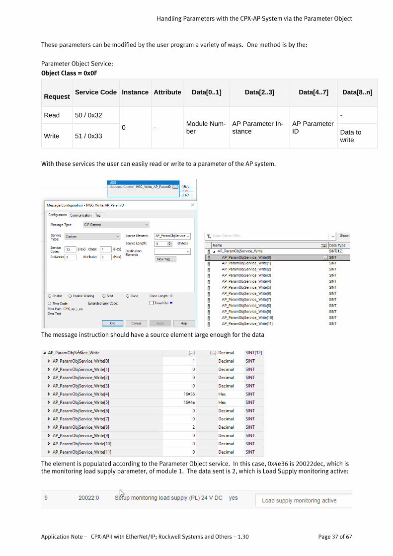
These parameters can be modified by the user program a variety of ways. One method is by the:
Parameter Object Service:
Object Class = 0x0F
Request Service Code Instance Attribute Data[0..1] Data[2..3] Data[4..7] Data[8..n]
Read 50 / 0x32
0 - Module Num-ber
AP Parameter In-stance
AP Parameter ID
-
Write 51 / 0x33 Data to write
With these services the user can easily read or write to a parameter of the AP system.
The message instruction should have a source element large enough for the data
The element is populated according to the Parameter Object service. In this case, 0x4e36 is 20022dec, which is the monitoring load supply parameter, of module 1. The data sent is 2, which is Load Supply monitoring active:
Handling Parameters with the CPX-AP System via the Parameter Object
Page 38 of 67 Application Note – CPX-AP-I with EtherNet/IP; Rockwell Systems and Others – 1.30
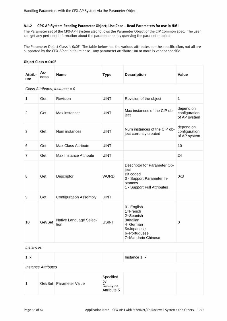
8.1.2 CPX-AP System Reading Parameter Object; Use Case – Read Parameters for use in HMI
The Parameter set of the CPX-AP-I system also follows the Parameter Object of the CIP Common spec. The user can get any pertinent information about the parameter set by querying the parameter object.
The Parameter Object Class is 0x0F. The table below has the various attributes per the specification, not all are supported by the CPX-AP at initial release. Any parameter attribute 100 or more is vendor specific.
Object Class = 0x0F
Attrib-ute
Ac-cess
Name Type Description Value
Class Attributes, Instance = 0
1 Get Revision UINT Revision of the object 1
2 Get Max instances UINT Max instances of the CIP ob-ject
depend on configuration of AP system
3 Get Num instances UINT Num instances of the CIP ob-ject currently created
depend on configuration of AP system
6 Get Max Class Attribute UINT 10
7 Get Max Instance Attribute UINT 24
8 Get Descriptor WORD
Descriptor for Parameter Ob-ject Bit coded 0 - Support Parameter In-stances 1 - Support Full Attributes
0x3
9 Get Configuration Assembly UINT
10 Get/Set Native Language Selec-tion
USINT
0 - English 1=French 2=Spanish 3=Italian 4=German 5=Japanese 6=Portuguese 7=Mandarin Chinese
0
Instances
1..x Instance 1..x
Instance Attributes
1 Get/Set Parameter Value
Specified by Datatype Attribute 5

Handling Parameters with the CPX-AP System via the Parameter Object
Application Note – CPX-AP-I with EtherNet/IP; Rockwell Systems and Others – 1.30 Page 39 of 67
2 Get/Set Link Path Size USINT Always zero (no link path available)
3 Get/Set Link Path EPATH Currently no link path support available
4 Get Descriptor WORD Descriptor of Parameter In-stance
5 Get Datatype USINT or ARRAY of USINT
Datatype definition of this in-stance
6 Get Datasize USINT
7 Get Parameter Name String SHORT_STRING
Max 16 chars
8 Get Units string SHORT_STRING
Max 4 chars
9 Get Help string SHORT_STRING
Max 64 chars
10 Get Minimum Value
Specified by Datatype Attribute 5
Minimum value of parameter instance. For string types this represents minimal length.
11 Get Maximum Value
Specified by Datatype Attribute 5
Maximum value of parameter instance. For string types this represents maximal length.
12 Get Default Value
Specified by Datatype Attribute 5
13 Get Scaling Multiplier UINT
14 Get Scaling Divisor UINT
15 Get Scaling Base UINT
16 Get Scaling Offset INT
17 Get Multiplier Link UINT
18 Get Divisor Link UINT
19 Get Base Link UINT
20 Get Offset Link UINT
21 Get Decimal Precision USINT
Handling Parameters with the CPX-AP System via the Parameter Object
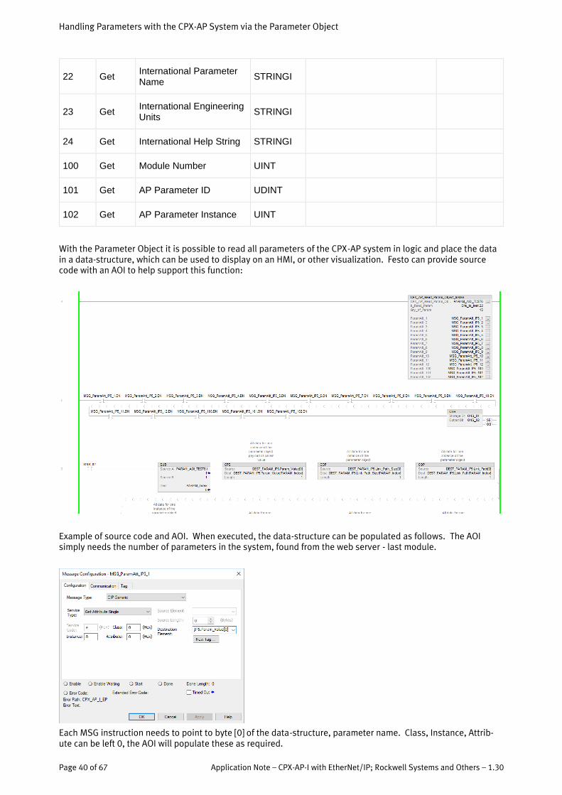
Page 40 of 67 Application Note – CPX-AP-I with EtherNet/IP; Rockwell Systems and Others – 1.30
22 Get International Parameter Name
STRINGI
23 Get International Engineering Units
STRINGI
24 Get International Help String STRINGI
100 Get Module Number UINT
101 Get AP Parameter ID UDINT
102 Get AP Parameter Instance UINT
With the Parameter Object it is possible to read all parameters of the CPX-AP system in logic and place the data in a data-structure, which can be used to display on an HMI, or other visualization. Festo can provide source code with an AOI to help support this function:
Example of source code and AOI. When executed, the data-structure can be populated as follows. The AOI simply needs the number of parameters in the system, found from the web server - last module.
Each MSG instruction needs to point to byte [0] of the data-structure, parameter name. Class, Instance, Attrib-ute can be left 0, the AOI will populate these as required.

Handling Parameters with the CPX-AP System via the Parameter Object
Application Note – CPX-AP-I with EtherNet/IP; Rockwell Systems and Others – 1.30 Page 41 of 67
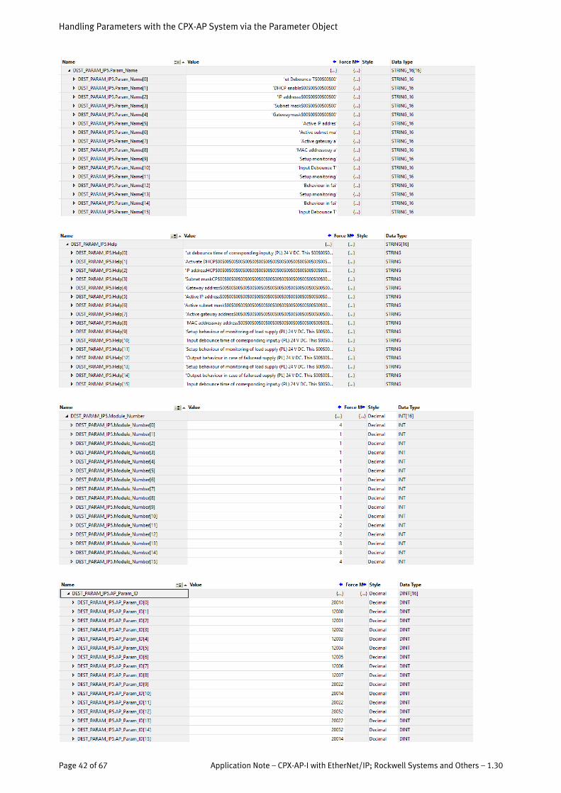
The data-structure can be copied from a template provided with the AOI. Simply create an array size for the QTY of parameters + 1. In this case, there were 15 parameters. Do not expand the variables called “buffer”.
The results are shown below for interesting parameters of the CPX-AP system. Array[1] through [15] are the data of the parameters in order 1 – 15. Array[0] is a temporary storage, and not to be used by the user.
Handling Parameters with the CPX-AP System via the Parameter Object
Page 42 of 67 Application Note – CPX-AP-I with EtherNet/IP; Rockwell Systems and Others – 1.30

Handling Parameters with the CPX-AP System via the Parameter Object
Application Note – CPX-AP-I with EtherNet/IP; Rockwell Systems and Others – 1.30 Page 43 of 67
8.1.3 CPX-AP System Stored Parameters
The Parameter set of the CPX-AP system can also store its parameters. First set all desired parameters. You can then store them by going to the Configuration->Stored Parameter option.
Your first time before storing, your options will be as follows.
• Default is to store current values. • You can use this page to restore all values to their default. • If you have a file from the same or a previous system with an EXACT configuration, you can also upload
the values from that file.
After submitting the values, they are stored in the CPX-AP EtherNet adapter. There are now additional options.
• Delete stored values • Download Stored Values
Hint: The Info Button has detailed information on the actions within Stored Parameters

IO-Link and ISDUs with the CPX-AP System via the IO-Link Object
Page 44 of 67 Application Note – CPX-AP-I with EtherNet/IP; Rockwell Systems and Others – 1.30
9 IO-Link and ISDUs with the CPX-AP System via the IO-Link Object
IO-Link is a point to point protocol commonly used for industrial devices that require bi-direction data exchange with up to 32 bytes of process data, also referred to as I/O data or Implicit data in EtherNet/IP . IO-Link also al-lows for exchange of configuration data via indexes and sub-indexes. This is referred to as service data, and can be accessed programmatically via an explicit message in EtherNet/IP. ISDU (Index service data unit) information can be found in the user manual of any IO-Link device.
Information
“ISDU-Access” (Index Service Data Unit Access) is the mechanism used for accessing data objects in all IO-Link devices. Each parameter has an index. Some may have sub-indexes in addition.
Information
Festo provides (May 2021) a convenient, easy to use software tool to configure the IO-Link master called, “Festo IO-Link Tool”. This uses the IODD file of any device to be parameterized on a PC, and for storage of the data on the master. It is not a necessity to programmatically access an ISDU, but it is possible via the user program. This chapter describes how to do this within Logix.
The IO-Link Service parameter Object – 10B hex , is an ODVA object for integrating IO-Link into the Common Industrial Protocol (CIP), which is the basis for EtherNet/IP. CIP mechanisms are used as much as possible to exchange data with an IO-Link device. So for example, if the identity of a device is desired, the CIP identity ob-ject is used to access it from an IO-Link device. To access an ISDU, the IO-Link object was created, and released in November 2019. This is EtherNet/IP CIP IO-Link, Volume 7C.
The parameters are device specific, and may be defined as both read / write. The user shall use a MSG instruc-tion to access these parameters in the Rockwell Logix environment. It is recommended to only access one index at a time.
9.1.1 CPX-AP IO-Link Module Basic Set-Up
There is a basic set-up required for the CPX-AP EtherNet/IP system required for IO-Link.

IO-Link and ISDUs with the CPX-AP System via the IO-Link Object
Application Note – CPX-AP-I with EtherNet/IP; Rockwell Systems and Others – 1.30 Page 45 of 67

IO-Link and ISDUs with the CPX-AP System via the IO-Link Object
Page 46 of 67 Application Note – CPX-AP-I with EtherNet/IP; Rockwell Systems and Others – 1.30
9.1.2 CPX-AP IO-Link Module Process Data
The Process Data will automatically be mapped to the device. Data will not be converted or parsed, which might be necessary depending on the IO-Link device. Integers will likely need to be byte-swapped.
9.1.3 CPX-AP ISDU Access with Explicit Message for Parameterizing
The following sections will describe how to read / write to IO-Link parameters using several CIP objects. Retriev-ing identity is done by routing messages to the device using the Identity Object Class code: 0x01. To exchange parameter data, we will use the new IO-Link Device Service Parameter Object Class Code: 0x10B. The basis of this messaging is the new definition of the CIP to IO-Link Translation Routing for Explicit messaging. The follow image shows an example:

IO-Link and ISDUs with the CPX-AP System via the IO-Link Object
Application Note – CPX-AP-I with EtherNet/IP; Rockwell Systems and Others – 1.30 Page 47 of 67
In this example, the 3 is required behind the IP address since 3 has been assigned as the IO-Link port in the ODVA spec. For the CPX-AP system, the IO-Link channels start counting with 1. Therefore, the first channel of the lowest IO-Link master is 1. If there are 2 IO-Link masters in a CPX-AP system, the lowest slot numbered IOL master has channels 1 to 4, the next has channels 5 to 8.
In addition to a new Object Class for IO-Link, this class comes with specific services to be used:
In this Logix example to the left:
- The “,3” after the device name (or IP address) is for routing the message to IO-Link.
- The “,2” is for the 2nd channel of the IOL master.
IO-Link and ISDUs with the CPX-AP System via the IO-Link Object
Page 48 of 67 Application Note – CPX-AP-I with EtherNet/IP; Rockwell Systems and Others – 1.30
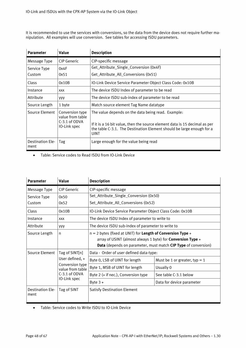
It is recommended to use the services with conversions, so the data from the device does not require further ma-nipulation. All examples will use conversion. See tables for accessing ISDU parameters.
Parameter Value Description
Message Type CIP Generic CIP-specific message
Service Type
Custom
0x4F
0x51
Get_Attribute_Single_Conversion (0x4F)
Get_Attribute_All_Conversions (0x51)
Class 0x10B IO-Link Device Service Parameter Object Class Code: 0x10B
Instance xxx The device ISDU Index of parameter to be read
Attribute yyy The device ISDU sub-index of parameter to be read
Source Length 1 byte Match source element Tag Name datatype
Source Element Conversion type value from table C-3.1 of ODVA IO-Link spec
The value depends on the data being read. Example:
If it is a 16 bit value, then the source element data is 15 decimal as per the table C-3.1. The Destination Element should be large enough for a UINT
Destination Ele-ment
Tag Large enough for the value being read
• Table: Service codes to Read ISDU from IO-Link Device
Parameter Value Description
Message Type CIP Generic CIP-specific message
Service Type
Custom
0x50
0x52
Set_Attribute_Single_Conversion (0x50)
Set_Attribute_All_Conversions (0x52)
Class 0x10B IO-Link Device Service Parameter Object Class Code: 0x10B
Instance xxx The device ISDU Index of parameter to write to
Attribute yyy The device ISDU sub-index of parameter to write to
Source Length n n = 2 bytes (fixed at UNIT) for Length of Conversion Type +
array of USINT (almost always 1 byte) for Conversion Type +
Data (depends on parameter, must match CIP Type of conversion)
Source Element Tag of SINT[n]
User defined, +
Conversion type value from table C-3.1 of ODVA IO-Link spec
Data - Order of user defined data-type:
Byte 0, LSB of UINT for length Must be 1 or greater, typ = 1
Byte 1, MSB of UINT for length Usually 0
Byte 2 (+ if nec.), Conversion type See table C-3.1 below
Byte 3 + Data for device parameter
Destination Ele-ment
Tag of SINT Satisfy Destination Element
• Table: Service codes to Write ISDU to IO-Link Device

IO-Link and ISDUs with the CPX-AP System via the IO-Link Object
Application Note – CPX-AP-I with EtherNet/IP; Rockwell Systems and Others – 1.30 Page 49 of 67
The following table includes the conversion codes for the IO-Link Object.
Cont…

IO-Link and ISDUs with the CPX-AP System via the IO-Link Object
Page 50 of 67 Application Note – CPX-AP-I with EtherNet/IP; Rockwell Systems and Others – 1.30
9.1.3.1 CPX-AP ISDU Access – MSG Instruction Read Data Example with Explicit Message
The following example uses a Balluff Smart Light BNI IOL-802-102-Z037. In this example, we will read the Brightness settings of the Smart Light, ISDU 0x51, found in their user manual.
The device is plugged into the 2nd channel of the CPX-AP-I-4IOL-M12. The settings are as above in section 8.1.1

IO-Link and ISDUs with the CPX-AP System via the IO-Link Object
Application Note – CPX-AP-I with EtherNet/IP; Rockwell Systems and Others – 1.30 Page 51 of 67
The MSG instruction is set as follows:
• Message Type : CIP Generic • Service code : 0x4F from IO-Link Service Parameter table for Get Attribute Single with Conversion • Class : 0x10B for IO-Link CIP Object • Instance : 81 dec (0x51) from the Balluff manual for Brightness setting ISDU index • Attribute : 0x00 for no ISDU sub-index • Source Length : 1 byte • Source Element is Tag Name created : IOL_CONV_TYPE as SINT
o The data is 23 (dec), which is from the IO-Link / CIP Type Mapping table, and used if you have
24 bits to convert. This converts the IO-Link datatype UIntegerT to UDINT in CIP. • Destination Element is Tag Name created : IOL_ISDU_Value_DINT as DINT
o The destination size datatype DINT is large enough for the result
• The path is the Ethernet module, 3 (for IO-Link Port), 2 (for 2nd channel of the IOL module)

IO-Link and ISDUs with the CPX-AP System via the IO-Link Object
Page 52 of 67 Application Note – CPX-AP-I with EtherNet/IP; Rockwell Systems and Others – 1.30
9.1.3.2 CPX-AP ISDU Access – MSG Instruction Write Data Example with Explicit Message
The following example uses a Balluff Smart Light BNI IOL-802-102-Z037. In this example, we will write a new value of the Brightness setting of the Smart Light, ISDU 0x51, found in their user manual. The device is plugged into the 2nd channel of the CPX-AP-I-4IOL-M12. The settings are as above in section 8.1.1 The MSG instruction is set as follows:
• Message Type : CIP Generic • Service code : 0x50 from IO-Link Service Parameter table for Set Attribute Single with Conversion • Class : 0x10B for IO-Link CIP Object • Instance : 81 dec (0x51) from the Balluff manual for Brightness setting ISDU index • Attribute : 0x00 for no ISDU sub-index • Source Length : 7 bytes • Source Element is Tag Name created : IOL_ISDU_SourceData as SINT[7]
o The data byte[0] is 1, which is 1 value for conversion type o The data byte[1] is 0, not needed, no additional values o The data byte [2] is 23 dec, which is from the IO-Link / CIP Type Mapping table, and used if you
have 24 bits to convert. This converts CIP DINT to IO-Link datatype UIntegerT. o The data bytes [3] to [5] are the 3 new bytes of data (32 dec or 0x20) to replace 7F7F7F in the
device. This will reduce the brightness of the Smart Light. o The data byte [6] is not used from the DINT
• Destination Element is Tag Name reused : IOL_CONV_TYPE

IO-Link and ISDUs with the CPX-AP System via the IO-Link Object
Application Note – CPX-AP-I with EtherNet/IP; Rockwell Systems and Others – 1.30 Page 53 of 67
• The path is the Ethernet module, 3 (for IO-Link Port), 2 (for 2nd channel of the IOL module)
9.1.3.3 CPX-AP ISDU Access – MSG Instruction Read Vendor ID Example with Explicit Message
The following example uses a Balluff Smart Light BNI IOL-802-102-Z037. In this example, we will read the ven-dor ID of the device. There is a virtual Identity Object connected to the virtual network. Therefore the same CIP Identity Object is used (Object Class Code: 0x01). The values returned are reorganized due to conflict with the IO-Link specifica-tion. For example, the Vendor ID is different for IO-Link vs. CIP, so a translation function is returned. The seman-tics are defined in the IO-Link specification for CIP. We will use the example for the IO-Link Vendor ID, which is attribute 2 (device type defined in CIP common). See chapter 5-2.1.2 in the IO-Link spec of ODVA, Volume 7C. The device is plugged into the 2nd channel of the CPX-AP-I-4IOL-M12. The settings are as above in section 8.1.1 The MSG instruction is set as follows:
• Message Type : Get Attribute Single • Service code : 0xe • Class : 0x1 for CIP Identity Object • Instance : 1 (only 1 instance of the Identity Object) • Attribute : 2 (Device Type shall be the IO-Link Vendor ID according to Vol 7C of the CIP spec) • Source Length / Element: N/A • Destination Element is Tag Name created : IOL_Vendor_ID as DINT • Path is the same as the others. 3=IO-Link; 2=the channel
The return from the Balluff device is their Vendor ID for IO-link:
Festo IO-Link Tool
Page 54 of 67 Application Note – CPX-AP-I with EtherNet/IP; Rockwell Systems and Others – 1.30
10 Festo IO-Link Tool
The Festo IO-Link Tool is a software tool to configure a CPX-AP IO-Link master. It uses the IODD file of any IO-Link device to allow it to be parameterized from a PC, and for storage of the settings to be placed in the master. This tool is available from the Festo website. Be sure to review the user manual that comes with the tool.
10.1.1 Getting Started
• Follow the installation instructions that comes with the IO-Link Tool software. • Be sure the appropriate CPX-AP IOLM master description file for EtherNet/IP is installed. • Be sure the IODD files necessary are imported or are already present in the IOL Tool, shown in the cata-
log window.
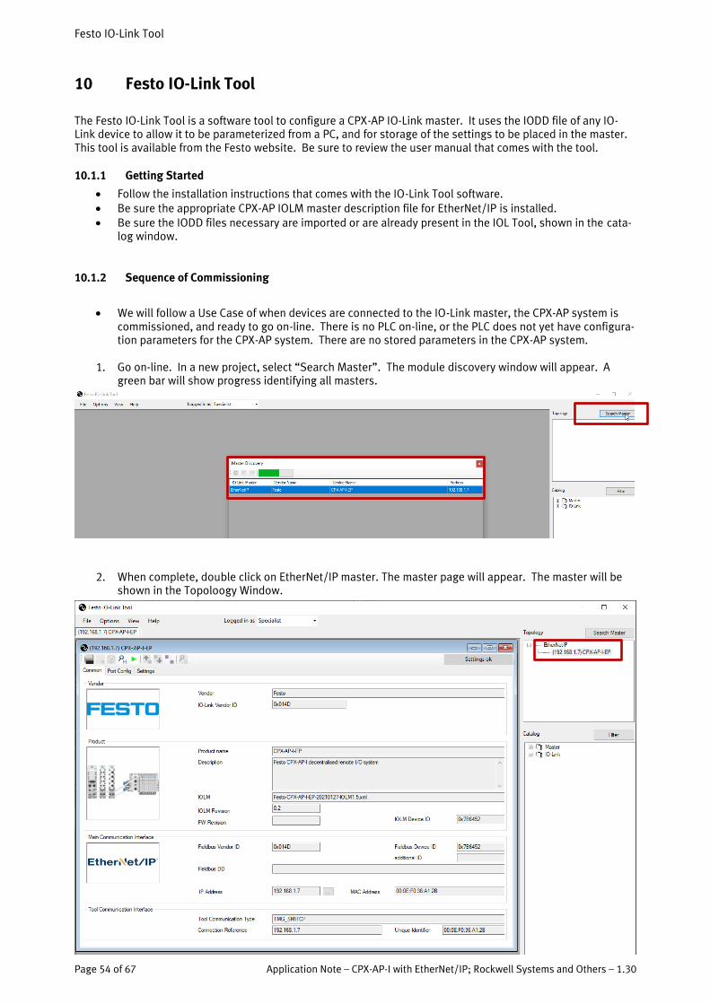
10.1.2 Sequence of Commissioning
• We will follow a Use Case of when devices are connected to the IO-Link master, the CPX-AP system is commissioned, and ready to go on-line. There is no PLC on-line, or the PLC does not yet have configura-tion parameters for the CPX-AP system. There are no stored parameters in the CPX-AP system.
1. Go on-line. In a new project, select “Search Master”. The module discovery window will appear. A green bar will show progress identifying all masters.
2. When complete, double click on EtherNet/IP master. The master page will appear. The master will be shown in the Topoloogy Window.

Festo IO-Link Tool
Application Note – CPX-AP-I with EtherNet/IP; Rockwell Systems and Others – 1.30 Page 55 of 67
3. Go to the Port Config tab. The Port addresses of the IOL master will be represented by the module num-ber, and port number of the module. Press the Green Arrow to go on-line.
4. Once on-line, a Green Bar will indicate on-line is active. Click on “Check Devices”, and a window will appear showing the connected devices at each port. Select “Takeover devices into engineering”.
Once taken-over, the Port Config page will contain the devices connected.
Festo IO-Link Tool
Page 56 of 67 Application Note – CPX-AP-I with EtherNet/IP; Rockwell Systems and Others – 1.30
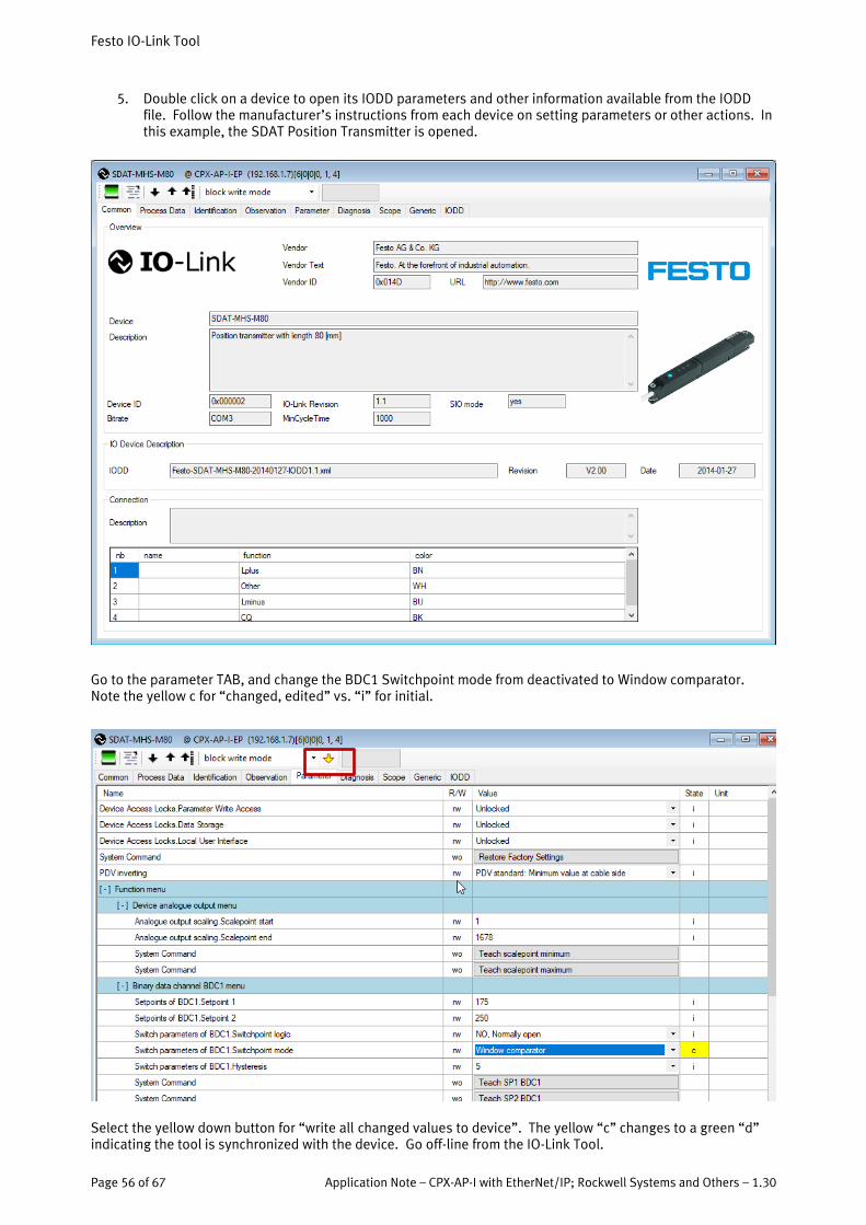
5. Double click on a device to open its IODD parameters and other information available from the IODD file. Follow the manufacturer’s instructions from each device on setting parameters or other actions. In this example, the SDAT Position Transmitter is opened.
Go to the parameter TAB, and change the BDC1 Switchpoint mode from deactivated to Window comparator. Note the yellow c for “changed, edited” vs. “i” for initial.
Select the yellow down button for “write all changed values to device”. The yellow “c” changes to a green “d” indicating the tool is synchronized with the device. Go off-line from the IO-Link Tool.

Festo IO-Link Tool
Application Note – CPX-AP-I with EtherNet/IP; Rockwell Systems and Others – 1.30 Page 57 of 67
6. Go to the webserver of the CPX-AP system. Click on the IOL master module. Set basic IOL module pa-rameters for the master. Many of the parameters are self-explanatory, but some require explanation:
Port Mode IOL_MANUAL The target device will operate via IO-Link based on the user defined configuration including validation from the choices below. Use this mode with Backup & Restore.
Port Mode IOL_AUTOSTART The target device will operate via IO-Link without the user defined configuration and validation. This will not work with Backup, Re-store, etc.
Port Mode DI_CQ The target device will operate as a digital input in SIO mode Port Mode PREOPERATE The master can assign parameters to the target device via ISDUs, but
it must be operating to exchange process data.
Type Compatible Device V1.1 – Backup & Restore
The target device supports V1.1 and data storage is enabled for both upload and download. When replacing a device, the device is auto-matically parameterized with the parameters stored in the master. But if the device was e.g. pre-parameterized with a USB IO-Link mas-ter, then the data is loaded from the device into the master.
Type Compatible Device V1.1 – Restore
The target device supports V1.1 and data storage is enabled for download. This is usually configured when an application has been accepted and the settings should no longer be changed.
In this example, IOL_MANUAL, and Backup + Restore for compatible devices are selected for each port with a device. There may be a discrepancy error at this time, ie, No Device Eventcode. Incompatible de-vice type, etc.

Festo IO-Link Tool
Page 58 of 67 Application Note – CPX-AP-I with EtherNet/IP; Rockwell Systems and Others – 1.30
In addition, for best usability with the IO-Link Tool, also manually enter the actual vendor and device ID (AP ID 20078 and 20079 of the IOL module) to the Nominal vendor and device ID (AP ID 20073 and 20080).
From default:
To actual:
7. Export this configuration to the PLC using the L5X function, or use Stored Parameters to save this con-figuration in the CPX-AP Ethernet adapter. Connect the PLC and RUN.

Festo IO-Link Tool
Application Note – CPX-AP-I with EtherNet/IP; Rockwell Systems and Others – 1.30 Page 59 of 67
Any refresh of the webserver will not show any discrepancy errors, if the devices listed are connected, compati-ble, and operating properly.

Festo IO-Link Tool
Page 60 of 67 Application Note – CPX-AP-I with EtherNet/IP; Rockwell Systems and Others – 1.30
8. Go back to the IO-Link SW Tool to check. Going back on-line will now show the port configuration from the data stored in the CPX-AP from the PLC configuration or from Stored Parameters.
9. Double click on the SDAT device in this example in port 1. Go to the parameter tab and then select the up-arrow for “upload from device”. The state of each parameter is synchronized with the device and the window comparator setting is still loaded in the device.

Festo IO-Link Tool
Application Note – CPX-AP-I with EtherNet/IP; Rockwell Systems and Others – 1.30 Page 61 of 67
10. If the device is disconnected, the status of the IO-Link Tool should show the device lost.
Reconnecting a new SDAT with the same part number will show the same values in step 9 if uploaded, since Backup + Restore is active. These values will be loaded into the new device.

Modbus TCP View
Page 62 of 67 Application Note – CPX-AP-I with EtherNet/IP; Rockwell Systems and Others – 1.30
11 Modbus TCP View
As of FW version 1.2.7, a Modbus View has been added to facilitate the addressing of a CPX-AP system with a Modbus controller.
11.1 Modbus TCP Overview for the CPX-AP System
The Views provide Modbus register addresses for I/O, Diagnostics, Parameters, Module, and IO-Link data points. In addition, other pertinent information is as follows:
a. LED Function
NS Green static: Device is online and has at least one connection. Green blink: Device is online and got an IP address, but no active connection Off: Device is offline
b. Holding Registers Overview
Description:
Register Length Access Name
0 4096 rw Outputs
5000 4096 r Inputs
10000 1000 r/w Parameter
11000 1000 r Diagnosis
12000 1 r Module Count
14000 2 r/w Timeout (default 100 ms)
14002 1 r/w Webserver Enable
14003 1 r/w Webserver Write Access Enable
14004 1 r/w SNMP Enable
15000 18500 r Module Information
34000 200 r/w IO-Link ISDU Mailbox

Modbus TCP View
Application Note – CPX-AP-I with EtherNet/IP; Rockwell Systems and Others – 1.30 Page 63 of 67
c. Timeout Address info:
14000 2 Int r/w Timeout (default 100 ms)
Description:
Modbus connection timeout in ms (default=100 ms). Value is stored in non-volatile memory Value of 0 turns the timeout off.
d. Parameter Execution
Description:
1 Read
2 Write
3 Busy (read or write currently running)
4 Error (request failed - status code in the upper 8 bit)
16 Done (request successfully completed)
A parameter read or write is initiated by writing the Exec register as last register of the request. Steps to execute a request:
Step Register Description
1 10000 write module number
2 10001 write parameter id
3 10002 write parameter instance
4 10004 and 10010..(10010 + datalen written in 10004) write datalen and data (only for write request)
5 10003 write 1 or 2 to exec register
6 10003 read back exec register until done or error
7 10004 and 10010... read datalen and data (only for read request)
e. IO-Link ISDU Access
Description:
Holding register Attribute Description
34000 ISDU Status 0 = OK 254 = Error 255 = Busy
34001 Read/Write Command
50 = Read (with byte swap) 51 = Write (with byte swap) 100 = Read 101 = Write
34002 Module Module number of an IO-Link Master
34003 Channel
34004 Index ISDU Index
34005 Subindex ISDU Subindex
34006 Length of data in Bytes (for read always zero)
34007..34126 Data (max 238 bytes)
Modbus TCP View
Page 64 of 67 Application Note – CPX-AP-I with EtherNet/IP; Rockwell Systems and Others – 1.30
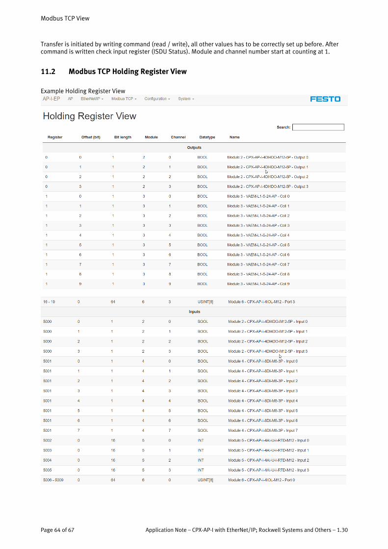
Transfer is initiated by writing command (read / write), all other values has to be correctly set up before. After command is written check input register (ISDU Status). Module and channel number start at counting at 1.
11.2 Modbus TCP Holding Register View
Example Holding Register View

Modbus TCP View
Application Note – CPX-AP-I with EtherNet/IP; Rockwell Systems and Others – 1.30 Page 65 of 67
Modbus TCP View
Page 66 of 67 Application Note – CPX-AP-I with EtherNet/IP; Rockwell Systems and Others – 1.30
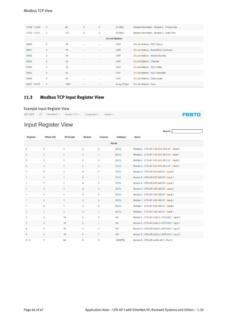
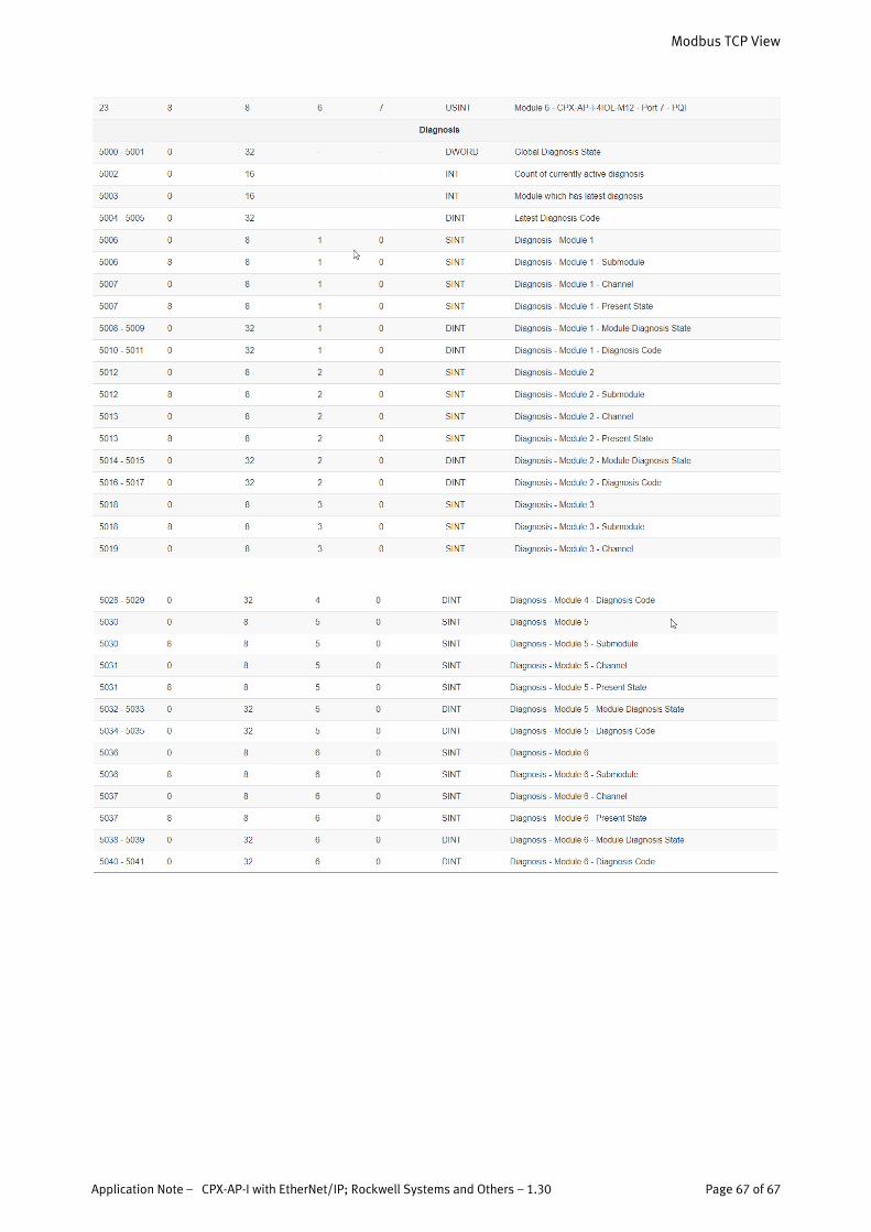
11.3 Modbus TCP Input Register View
Example Input Register View
Modbus TCP View
Application Note – CPX-AP-I with EtherNet/IP; Rockwell Systems and Others – 1.30 Page 67 of 67