application note: aph005 - decawave ltd 2: tx current profiles for different preamble lengths (no...
TRANSCRIPT

© DecaWave 2013 This document is confidential and contains information which is proprietary to DecaWave Limited. No reproduction is permitted without prior express written permission of the author
APPLICATION NOTE: APH005
APH005 APPLICATION NOTE
DW1000 POWER SOURCE SELECTION GUIDE
Selecting the power source for your DW1000 based product
Version 1.10
This document is subject to change without notice

APH005 DW1000 Power Source Selection Guide
© DecaWave 2013 This document is confidential and contains information which is proprietary to DecaWave Limited. No reproduction is permitted without prior express written permission of the author
Page 2 of 20
TABLE OF CONTENTS
1 INTRODUCTION ..................................................................................................................... 4
1.1 OVERVIEW ................................................................................................................................... 4 1.2 BATTERY TYPES TESTED .................................................................................................................. 4 1.3 SUMMARY OF RESULTS .................................................................................................................. 4
2 DW1000 POWER SUPPLY OVERVIEW ..................................................................................... 5
2.1 MODES OF OPERATION AND THEIR IMPACT ON SUPPLY CHOICE ............................................................. 6 2.1.1 TX only operation .............................................................................................................. 6 2.1.2 RX and TX operation .......................................................................................................... 7
3 PERFORMANCE OVER SUPPLY VOLTAGE ................................................................................ 9
3.1 TX POWER LEVEL OVER SUPPLY VOLTAGE .......................................................................................... 9 3.2 RECEIVER SENSITIVITY .................................................................................................................. 10 3.3 RECEIVER QUALITY (CHANNEL IMPULSE RESPONSE QUALITY) ............................................................. 11
4 BATTERY TEST RESULTS ....................................................................................................... 12
4.1 BUTTON CELL (CR2477).............................................................................................................. 12 4.2 LI-POLY ..................................................................................................................................... 12 4.3 ALKALINE AA (DURACELL) ............................................................................................................ 12 4.4 ALKALINE AAA (DURACELL) .......................................................................................................... 12 4.5 RECHARGEABLE AA (NI-MH - DURACELL)....................................................................................... 12 4.6 RECHARGEABLE AAA (NI-MH - DURACELL) .................................................................................... 13 4.7 RECEIVE SENSITIVITY PLOTS FOR DIFFERENT BATTERIES ...................................................................... 13
5 BATTERY LIFE ...................................................................................................................... 15
6 ADDITIONAL BATTERY MANAGEMENT CONSIDERATIONS ..................................................... 17
7 REVISION HISTORY .............................................................................................................. 18
8 MAJOR CHANGES ................................................................................................................ 18
9 REFERENCES ........................................................................................................................ 19
9.1 LISTING ..................................................................................................................................... 19
10 ABOUT DECAWAVE .......................................................................................................... 20
LIST OF TABLES
TABLE 1: BATTERY TYPES TESTED TO DATE ........................................................................................................................ 4 TABLE 2: SUMMARY OF TEST RESULTS .............................................................................................................................. 4 TABLE 3: RANGING PERFORMANCE OVER SUPPLY VOLTAGE ................................................................................................ 11 TABLE 4: BATTERY LIFE CALCULATION ............................................................................................................................ 15 TABLE 1: DOCUMENT HISTORY .................................................................................................................................... 18 TABLE 5: TABLE OF REFERENCES ................................................................................................................................... 19
LIST OF FIGURES
FIGURE 1: DW1000 POWER SUPPLY OVERVIEW ................................................................................................................ 5 FIGURE 2: TX CURRENT PROFILES FOR DIFFERENT PREAMBLE LENGTHS (NO DC-DC CONVERTER) ................................................ 6 FIGURE 3: COMPARISON SHOWING TX CURRENT WITH AND WITHOUT A DC-DC CONVERTER ON THE 3.3 V SUPPLY........................ 7 FIGURE 4: TYPICAL TWR POWER PROFILE FOR A TAG USING A DC-DC CONVERTER. CHANNEL 5, 6.8 MBPS, 128 SYMBOL PREAMBLE.
....................................................................................................................................................................... 7
APH005 DW1000 Power Source Selection Guide
© DecaWave 2013 This document is confidential and contains information which is proprietary to DecaWave Limited. No reproduction is permitted without prior express written permission of the author
Page 3 of 20
FIGURE 5: RX CURRENT CONSUMPTION DIFFERENCE WHEN USING A DC-DC CONVERTER AT 1.8 V. CHANNEL 5, 6.8 MBPS, 128
SYMBOL PREAMBLE. ............................................................................................................................................. 8 FIGURE 6: TX POWER LEVEL VERSUS VDDPA SUPPLY VOLTAGE FOR 4 DIFFERENT DEVICES ......................................................... 9 FIGURE 7: RX SENSITIVITY VERSUS SUPPLY VOLTAGE FOR 110 KBPS DATA RATE ...................................................................... 10 FIGURE 8: RX SENSITIVITY VERSUS SUPPLY VOLTAGE FOR 6.81 MBPS DATA RATE ................................................................... 10 FIGURE 9: CIR RESPONSE OVERLAYS ALL CENTRED ON FIRST PATH (RED LINE) ......................................................................... 11 FIGURE 10: RX SENSITIVITY PLOTS FOR VARIOUS BATTERY OPTIONS (110 KBPS DATA RATE) ...................................................... 13 FIGURE 11: RX SENSITIVITY PLOTS FOR VARIOUS BATTERY OPTIONS (6.81 MBPS DATA RATE) ................................................... 14 FIGURE 12: BATTERY LIFE ESTIMATES AS THE TX BLINK RATE VARIES .................................................................................... 16
APH005 DW1000 Power Source Selection Guide
© DecaWave 2013 This document is confidential and contains information which is proprietary to DecaWave Limited. No reproduction is permitted without prior express written permission of the author
Page 4 of 20
1 INTRODUCTION
1.1 Overview
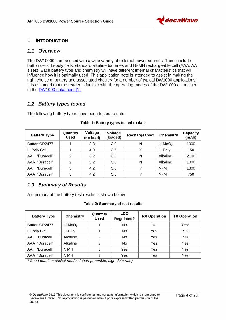
The DW10000 can be used with a wide variety of external power sources. These include button cells, Li-poly cells, standard alkaline batteries and Ni-MH rechargeable cell (AAA, AA sizes). Each battery type and chemistry will have different internal characteristics that will influence how it is optimally used. This application note is intended to assist in making the right choice of battery and associated circuitry for a number of typical DW1000 applications. It is assumed that the reader is familiar with the operating modes of the DW1000 as outlined in the DW1000 datasheet [1].
1.2 Battery types tested
The following battery types have been tested to date:
Table 1: Battery types tested to date
Battery Type Quantity
Used
Voltage
(no load)
Voltage (loaded)
Rechargeable? Chemistry Capacity
(mAh)
Button CR2477 1 3.3 3.0 N Li-MnO2 1000
Li-Poly Cell 1 4.0 3.7 Y Li-Poly 150
AA “Duracell” 2 3.2 3.0 N Alkaline 2100
AAA “Duracell” 2 3.2 3.0 N Alkaline 1000
AA “Duracell” 3 4.2 3.6 Y Ni-MH 1300
AAA “Duracell” 3 4.2 3.6 Y Ni-MH 750
1.3 Summary of Results
A summary of the battery test results is shown below:
Table 2: Summary of test results
Battery Type Chemistry Quantity
Used
LDO
Regulated? RX Operation TX Operation
Button CR2477 Li-MnO2 1 No No Yes*
Li-Poly Cell Li-Poly 1 No Yes Yes
AA “Duracell” Alkaline 2 No Yes Yes
AAA “Duracell” Alkaline 2 No Yes Yes
AA “Duracell” NiMH 3 Yes Yes Yes
AAA “Duracell” NiMH 3 Yes Yes Yes
* Short duration packet modes (short preamble, high data rate)
APH005 DW1000 Power Source Selection Guide
© DecaWave 2013 This document is confidential and contains information which is proprietary to DecaWave Limited. No reproduction is permitted without prior express written permission of the author
Page 5 of 20
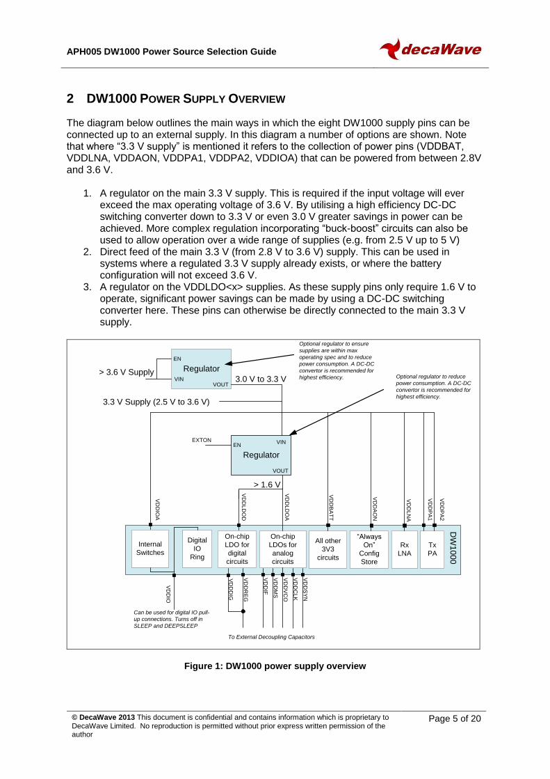
2 DW1000 POWER SUPPLY OVERVIEW
The diagram below outlines the main ways in which the eight DW1000 supply pins can be connected up to an external supply. In this diagram a number of options are shown. Note that where “3.3 V supply” is mentioned it refers to the collection of power pins (VDDBAT, VDDLNA, VDDAON, VDDPA1, VDDPA2, VDDIOA) that can be powered from between 2.8V and 3.6 V.
1. A regulator on the main 3.3 V supply. This is required if the input voltage will ever exceed the max operating voltage of 3.6 V. By utilising a high efficiency DC-DC switching converter down to 3.3 V or even 3.0 V greater savings in power can be achieved. More complex regulation incorporating “buck-boost” circuits can also be used to allow operation over a wide range of supplies (e.g. from 2.5 V up to 5 V)
2. Direct feed of the main 3.3 V (from 2.8 V to 3.6 V) supply. This can be used in systems where a regulated 3.3 V supply already exists, or where the battery configuration will not exceed 3.6 V.
3. A regulator on the VDDLDO<x> supplies. As these supply pins only require 1.6 V to operate, significant power savings can be made by using a DC-DC switching converter here. These pins can otherwise be directly connected to the main 3.3 V supply.
On-chip
LDOs for
analog
circuits
VD
DS
YN
VD
DC
LK
VD
DV
CO
VD
DM
S
VD
DIF
VD
DL
NA
VD
DP
A1
VD
DIO
VD
DIO
A
VD
DL
DO
A
VD
DL
DO
D
VD
DB
AT
T
VD
DR
EG
VD
DA
ON
On-chip
LDO for
digital
circuits
Rx
LNA
Tx
PA
“Always
On”
Config
Store
All other
3V3
circuits
To External Decoupling Capacitors
Internal
Switches
VD
DD
IG
DW
10
00
Digital
IO
Ring
VD
DP
A2
Regulator
EXTONEN
VIN
VOUT
> 1.6 V
3.3 V Supply (2.5 V to 3.6 V)
Regulator
EN
VINVOUT
> 3.6 V Supply3.0 V to 3.3 V
Can be used for digital IO pull-
up connections. Turns off in
SLEEP and DEEPSLEEP
Optional regulator to ensure
supplies are within max
operating spec and to reduce
power consumption. A DC-DC
convertor is recommended for
highest efficiency. Optional regulator to reduce
power consumption. A DC-DC
convertor is recommended for
highest efficiency.
Figure 1: DW1000 power supply overview
APH005 DW1000 Power Source Selection Guide
© DecaWave 2013 This document is confidential and contains information which is proprietary to DecaWave Limited. No reproduction is permitted without prior express written permission of the author
Page 6 of 20
2.1 Modes of Operation and their impact on supply choice
Depending on the users requirements, the external power supply requirements may be broken down in to two categories of operation. The first is where the DW1000 will only be used for TX (e.g. a TDOA tag); the second category is when the DW1000 will be used in both TX and RX modes (e.g. Two-Way Ranging, data communication).
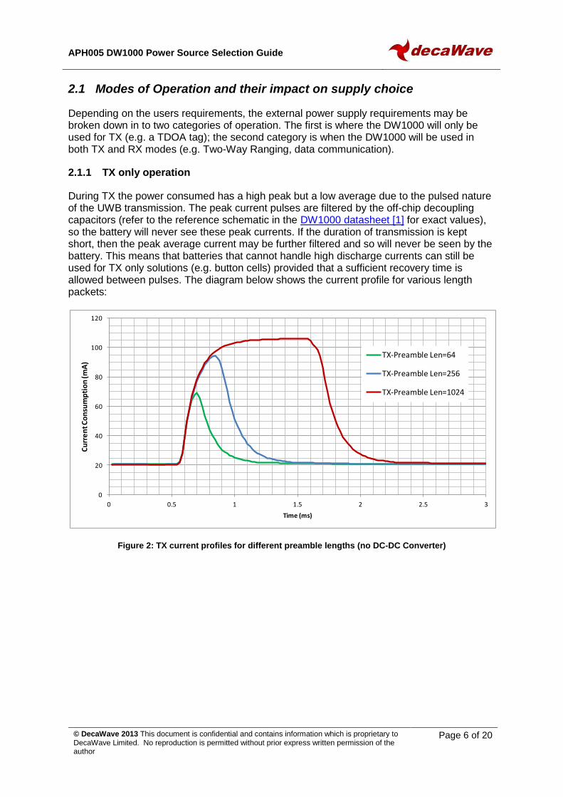
2.1.1 TX only operation
During TX the power consumed has a high peak but a low average due to the pulsed nature of the UWB transmission. The peak current pulses are filtered by the off-chip decoupling capacitors (refer to the reference schematic in the DW1000 datasheet [1] for exact values), so the battery will never see these peak currents. If the duration of transmission is kept short, then the peak average current may be further filtered and so will never be seen by the battery. This means that batteries that cannot handle high discharge currents can still be used for TX only solutions (e.g. button cells) provided that a sufficient recovery time is allowed between pulses. The diagram below shows the current profile for various length packets:
Figure 2: TX current profiles for different preamble lengths (no DC-DC Converter)
0
20
40
60
80
100
120
0 0.5 1 1.5 2 2.5 3
Cu
rre
nt C
on
sum
pti
on
(mA
)
Time (ms)
TX-Preamble Len=64
TX-Preamble Len=256
TX-Preamble Len=1024
APH005 DW1000 Power Source Selection Guide
© DecaWave 2013 This document is confidential and contains information which is proprietary to DecaWave Limited. No reproduction is permitted without prior express written permission of the author
Page 7 of 20
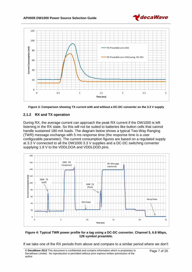
Figure 3: Comparison showing TX current with and without a DC-DC converter on the 3.3 V supply
2.1.2 RX and TX operation
During RX, the average current can approach the peak RX current if the DW1000 is left listening in the RX state. So this will not be suited to batteries like button cells that cannot handle sustained 180 mA loads. The diagram below shows a typical Two-Way Ranging (TWR) message exchange with 5 ms response time (the response time is a user configurable parameter). The current consumption figures are based on a regulated supply at 3.3 V connected to all the DW1000 3.3 V supplies and a DC-DC switching converter supplying 1.8 V to the VDDLDOA and VDDLDOD pins.
Figure 4: Typical TWR power profile for a tag using a DC-DC converter. Channel 5, 6.8 Mbps, 128 symbol preamble.
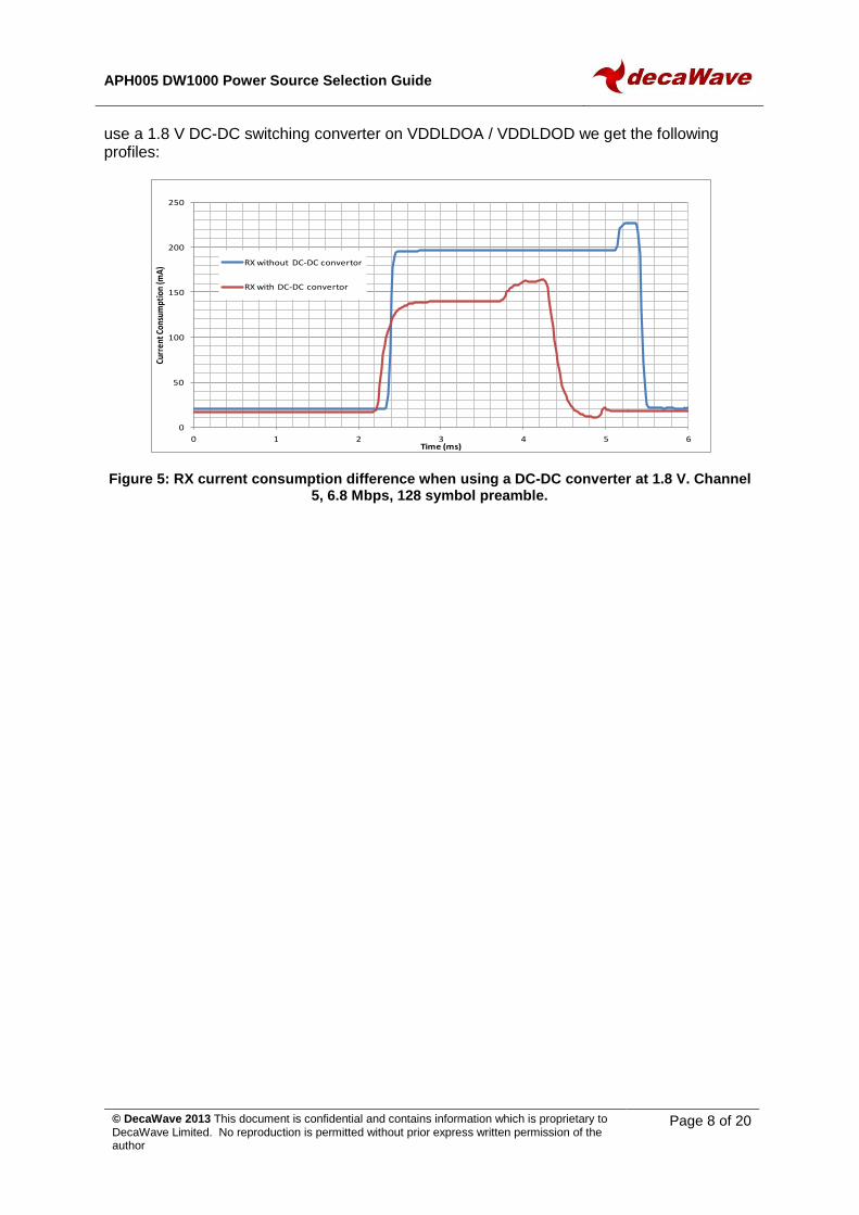
If we take one of the RX periods from above and compare to a similar period where we don’t
0
20
40
60
80
100
120
0 0.5 1 1.5 2 2.5 3
Cu
rre
nt
Co
nsu
mp
tio
n (
mA
)
Time (ms)
TX-Preamble Len=256
TX-Preamble Len=256 (using DC-DC)
0
20
40
60
80
100
120
140
160
180
0 5 10 15 20 25
Cu
rre
nt
Co
nsu
mp
tio
n (
mA
)
Time (ms)
2WR - TX(poll)
2WR - RX (response)
2WR -TX (final)
RX Message (optional)
Sleep State
IDLE State
APH005 DW1000 Power Source Selection Guide
© DecaWave 2013 This document is confidential and contains information which is proprietary to DecaWave Limited. No reproduction is permitted without prior express written permission of the author
Page 8 of 20
use a 1.8 V DC-DC switching converter on VDDLDOA / VDDLDOD we get the following profiles:
Figure 5: RX current consumption difference when using a DC-DC converter at 1.8 V. Channel 5, 6.8 Mbps, 128 symbol preamble.
0
50
100
150
200
250
0 1 2 3 4 5 6
Curr
ent C
onsu
mpt
ion
(mA
)
Time (ms)
RX without DC-DC convertor
RX with DC-DC convertor

APH005 DW1000 Power Source Selection Guide
© DecaWave 2013 This document is confidential and contains information which is proprietary to DecaWave Limited. No reproduction is permitted without prior express written permission of the author
Page 9 of 20
3 PERFORMANCE OVER SUPPLY VOLTAGE
When considering different power supply options we must ensure stability of operation over the operational voltage range. For this we need to consider both the RX sensitivity and also the quality of the accumulated Channel Impulse Response (CIR). For the transmitter we need to consider the spectral shape and output power level.
3.1 TX Power Level over supply voltage
TX Power level varies with the voltage level of VDDPA1 and VDDPA2 supplies. This variation in TX power can be compensated for by adjusting the TX power level based on the reading of the voltage on the VDDBAT pin from the onboard ADC. The variation in TX power for a number of different DW1000s is shown below.
Figure 6: TX Power Level versus VDDPA supply voltage for 4 different devices
-35
-34.5
-34
-33.5
-33
-32.5
-32
-31.5
-31
-30.5
2.7 2.9 3.1 3.3 3.5 3.7
TX P
ow
er
Leve
l (d
Bm
)
Supply Voltage (V)
APH005 DW1000 Power Source Selection Guide
© DecaWave 2013 This document is confidential and contains information which is proprietary to DecaWave Limited. No reproduction is permitted without prior express written permission of the author
Page 10 of 20
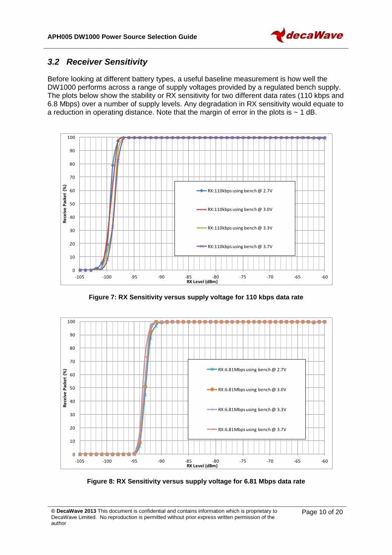
3.2 Receiver Sensitivity
Before looking at different battery types, a useful baseline measurement is how well the DW1000 performs across a range of supply voltages provided by a regulated bench supply. The plots below show the stability or RX sensitivity for two different data rates (110 kbps and 6.8 Mbps) over a number of supply levels. Any degradation in RX sensitivity would equate to a reduction in operating distance. Note that the margin of error in the plots is ~ 1 dB.
Figure 7: RX Sensitivity versus supply voltage for 110 kbps data rate
Figure 8: RX Sensitivity versus supply voltage for 6.81 Mbps data rate
0
10
20
30
40
50
60
70
80
90
100
-105 -100 -95 -90 -85 -80 -75 -70 -65 -60
Re
ceiv
e P
acke
t (%
)
RX Level (dBm)
RX:110kbps using bench @ 2.7V
RX:110kbps using bench @ 3.0V
RX:110kbps using bench @ 3.3V
RX:110kbps using bench @ 3.7V
0
10
20
30
40
50
60
70
80
90
100
-105 -100 -95 -90 -85 -80 -75 -70 -65 -60
Re
ceiv
e P
acke
t (%
)
RX Level (dBm)
RX:6.81Mbps using bench @ 2.7V
RX:6.81Mbps using bench @ 3.0V
RX:6.81Mbps using bench @ 3.3V
RX:6.81Mbps using bench @ 3.7V

APH005 DW1000 Power Source Selection Guide
© DecaWave 2013 This document is confidential and contains information which is proprietary to DecaWave Limited. No reproduction is permitted without prior express written permission of the author
Page 11 of 20
3.3 Receiver Quality (Channel Impulse Response Quality)
To verify that the power solutions have no impact on the receiver performance it is necessary to check both the RX sensitivity and also the RX Channel Impulse Response (CIR). In a system where the RX sensitivity shows no degradation, it is possible to have poor CIR’s which will impact the precision of the first path and hence the precision of the reported range. The figure below shows 150 overlaid RX CIRs. This visual check and the reported ranging statistics were used to check for any degradation in the channel response due to power supply choice.
Figure 9: CIR response overlays all centred on first path (red line)
The results for mean ranging distance and standard deviation across the supply voltage are:
Table 3: Ranging performance over supply voltage
Mode Supply
Voltage (V)
Ranging Mean (m)
Ranging
StdDev (m)
TX/RX
2.7 2.487 0.029
3.0 2.478 0.034
3.3 2.475 0.033
3.7 2.465 0.033
Any degradation in the CIR response due to the supply voltage would result in a large variation in the standard deviation. The above results show no degradation and all of the variances are within the measurement error.
APH005 DW1000 Power Source Selection Guide
© DecaWave 2013 This document is confidential and contains information which is proprietary to DecaWave Limited. No reproduction is permitted without prior express written permission of the author
Page 12 of 20
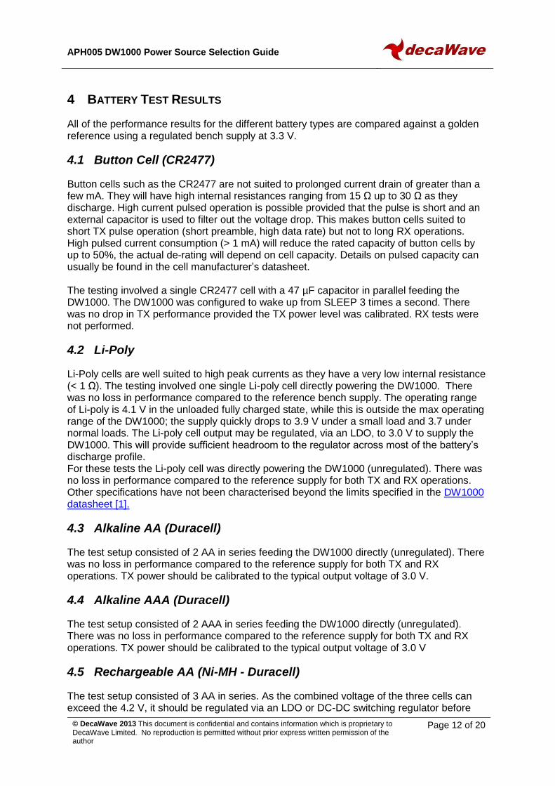
4 BATTERY TEST RESULTS
All of the performance results for the different battery types are compared against a golden reference using a regulated bench supply at 3.3 V.
4.1 Button Cell (CR2477)
Button cells such as the CR2477 are not suited to prolonged current drain of greater than a few mA. They will have high internal resistances ranging from 15 Ω up to 30 Ω as they discharge. High current pulsed operation is possible provided that the pulse is short and an external capacitor is used to filter out the voltage drop. This makes button cells suited to short TX pulse operation (short preamble, high data rate) but not to long RX operations. High pulsed current consumption (> 1 mA) will reduce the rated capacity of button cells by up to 50%, the actual de-rating will depend on cell capacity. Details on pulsed capacity can usually be found in the cell manufacturer’s datasheet. The testing involved a single CR2477 cell with a 47 µF capacitor in parallel feeding the DW1000. The DW1000 was configured to wake up from SLEEP 3 times a second. There was no drop in TX performance provided the TX power level was calibrated. RX tests were not performed.
4.2 Li-Poly
Li-Poly cells are well suited to high peak currents as they have a very low internal resistance (< 1 Ω). The testing involved one single Li-poly cell directly powering the DW1000. There was no loss in performance compared to the reference bench supply. The operating range of Li-poly is 4.1 V in the unloaded fully charged state, while this is outside the max operating range of the DW1000; the supply quickly drops to 3.9 V under a small load and 3.7 under normal loads. The Li-poly cell output may be regulated, via an LDO, to 3.0 V to supply the DW1000. This will provide sufficient headroom to the regulator across most of the battery’s discharge profile. For these tests the Li-poly cell was directly powering the DW1000 (unregulated). There was no loss in performance compared to the reference supply for both TX and RX operations. Other specifications have not been characterised beyond the limits specified in the DW1000 datasheet [1].
4.3 Alkaline AA (Duracell)
The test setup consisted of 2 AA in series feeding the DW1000 directly (unregulated). There was no loss in performance compared to the reference supply for both TX and RX operations. TX power should be calibrated to the typical output voltage of 3.0 V.
4.4 Alkaline AAA (Duracell)
The test setup consisted of 2 AAA in series feeding the DW1000 directly (unregulated). There was no loss in performance compared to the reference supply for both TX and RX operations. TX power should be calibrated to the typical output voltage of 3.0 V
4.5 Rechargeable AA (Ni-MH - Duracell)
The test setup consisted of 3 AA in series. As the combined voltage of the three cells can exceed the 4.2 V, it should be regulated via an LDO or DC-DC switching regulator before
APH005 DW1000 Power Source Selection Guide
© DecaWave 2013 This document is confidential and contains information which is proprietary to DecaWave Limited. No reproduction is permitted without prior express written permission of the author
Page 13 of 20
supplying the DW1000. For these tests an LDO was used with an output voltage of 3.3 V. There was no loss in performance compared to the reference supply for both TX and RX operations.
4.6 Rechargeable AAA (Ni-MH - Duracell)
The test setup consisted of 3 AAA in series. As the combined voltage of the three cells can exceed the 4.2 V, it should be regulated via an LDO or DC-DC switching regulator before supplying the DW1000. For these tests an LDO was used with an output voltage of 3.3 V. There was no loss in performance compared to the reference supply for both TX and RX operations.
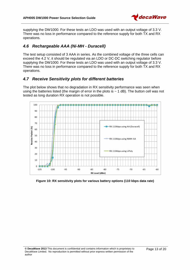
4.7 Receive Sensitivity plots for different batteries
The plot below shows that no degradation in RX sensitivity performance was seen when using the batteries listed (the margin of error in the plots is ~ 1 dB). The button cell was not tested as long duration RX operation is not possible.
Figure 10: RX sensitivity plots for various battery options (110 kbps data rate)
0
10
20
30
40
50
60
70
80
90
100
-105 -100 -95 -90 -85 -80 -75 -70 -65 -60
Re
ceiv
e P
acke
t (%
)
RX Level (dBm)
RX:110kbps using AA (Duracell)
RX:110kbps using NiMH AA
RX:110kbps using LiPoly

APH005 DW1000 Power Source Selection Guide
© DecaWave 2013 This document is confidential and contains information which is proprietary to DecaWave Limited. No reproduction is permitted without prior express written permission of the author
Page 14 of 20
Figure 11: RX sensitivity plots for various battery options (6.81 Mbps data rate)
0
10
20
30
40
50
60
70
80
90
100
-105 -100 -95 -90 -85 -80 -75 -70 -65 -60
Re
ceiv
e P
acke
t (%
)
RX Level (dBm)
RX:6.81Mbps using LiPoly
RX:6.81Mbps using AA (Durcell)
RX:6.81Mbps using NiMH AA
APH005 DW1000 Power Source Selection Guide
© DecaWave 2013 This document is confidential and contains information which is proprietary to DecaWave Limited. No reproduction is permitted without prior express written permission of the author
Page 15 of 20
5 BATTERY LIFE
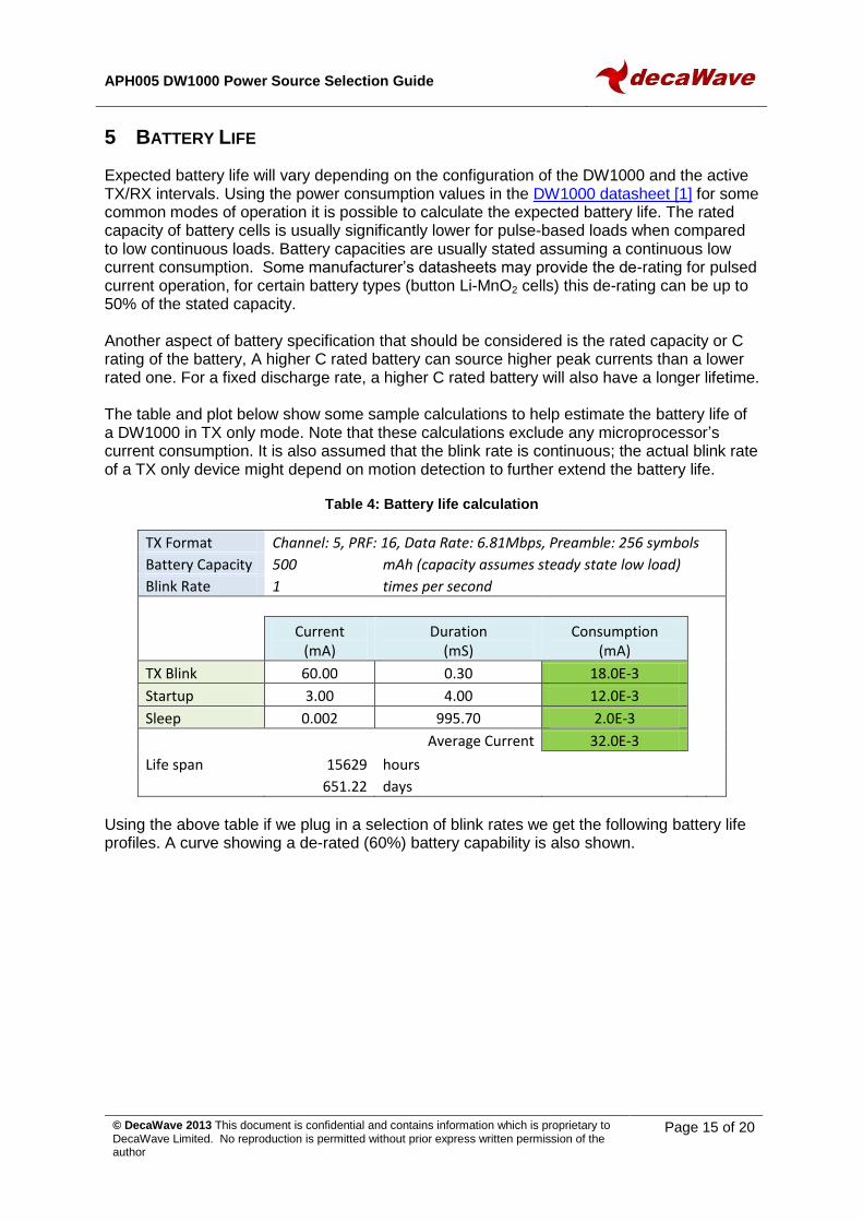
Expected battery life will vary depending on the configuration of the DW1000 and the active TX/RX intervals. Using the power consumption values in the DW1000 datasheet [1] for some common modes of operation it is possible to calculate the expected battery life. The rated capacity of battery cells is usually significantly lower for pulse-based loads when compared to low continuous loads. Battery capacities are usually stated assuming a continuous low current consumption. Some manufacturer’s datasheets may provide the de-rating for pulsed current operation, for certain battery types (button Li-MnO2 cells) this de-rating can be up to 50% of the stated capacity. Another aspect of battery specification that should be considered is the rated capacity or C rating of the battery, A higher C rated battery can source higher peak currents than a lower rated one. For a fixed discharge rate, a higher C rated battery will also have a longer lifetime. The table and plot below show some sample calculations to help estimate the battery life of a DW1000 in TX only mode. Note that these calculations exclude any microprocessor’s current consumption. It is also assumed that the blink rate is continuous; the actual blink rate of a TX only device might depend on motion detection to further extend the battery life.
Table 4: Battery life calculation
TX Format Channel: 5, PRF: 16, Data Rate: 6.81Mbps, Preamble: 256 symbols
Battery Capacity 500 mAh (capacity assumes steady state low load)
Blink Rate 1 times per second
Current
(mA) Duration
(mS) Consumption
(mA)
TX Blink 60.00 0.30 18.0E-3
Startup 3.00 4.00 12.0E-3
Sleep 0.002 995.70 2.0E-3
Average Current 32.0E-3
Life span 15629 hours
651.22 days
Using the above table if we plug in a selection of blink rates we get the following battery life profiles. A curve showing a de-rated (60%) battery capability is also shown.

APH005 DW1000 Power Source Selection Guide
© DecaWave 2013 This document is confidential and contains information which is proprietary to DecaWave Limited. No reproduction is permitted without prior express written permission of the author
Page 16 of 20
Figure 12: Battery life estimates as the TX blink rate varies
0
365
730
1095
1460
0 0.5 1 1.5 2 2.5 3 3.5 4
Batt
ery
life
(day
s)
Blink Rate (times per second)
No battery derating
Battery derated to 60% of capacity

APH005 DW1000 Power Source Selection Guide
© DecaWave 2013 This document is confidential and contains information which is proprietary to DecaWave Limited. No reproduction is permitted without prior express written permission of the author
Page 17 of 20
6 ADDITIONAL BATTERY MANAGEMENT CONSIDERATIONS
When designing a complete power solution a number of additional requirements may need to be considered: -
1. Additional circuits (microprocessor) supply levels. Are the supply levels common? 2. Blink rate, fixed frequency or motion sensitivity requirements. 3. Rechargeable battery and the associated recharging circuits. Additional active
circuits that will impact the DEEPSLEEP current consumption. Use of the EXTON pin from the DW1000 to shut devices down during SLEEP and DEEPSLEEP states.
4. System power consumption can be reduced by using DC-DC switching regulators on the low voltage VDDLDOA and VDDLDOD rails. This has implications for BOM cost.
5. The use of Buck-Boost converters to allow lower battery voltages (single AA cells) to be used while maintaining the minimum supply voltage to the DW1000.
APH005 DW1000 Power Source Selection Guide
© DecaWave 2013 This document is confidential and contains information which is proprietary to DecaWave Limited. No reproduction is permitted without prior express written permission of the author
Page 18 of 20
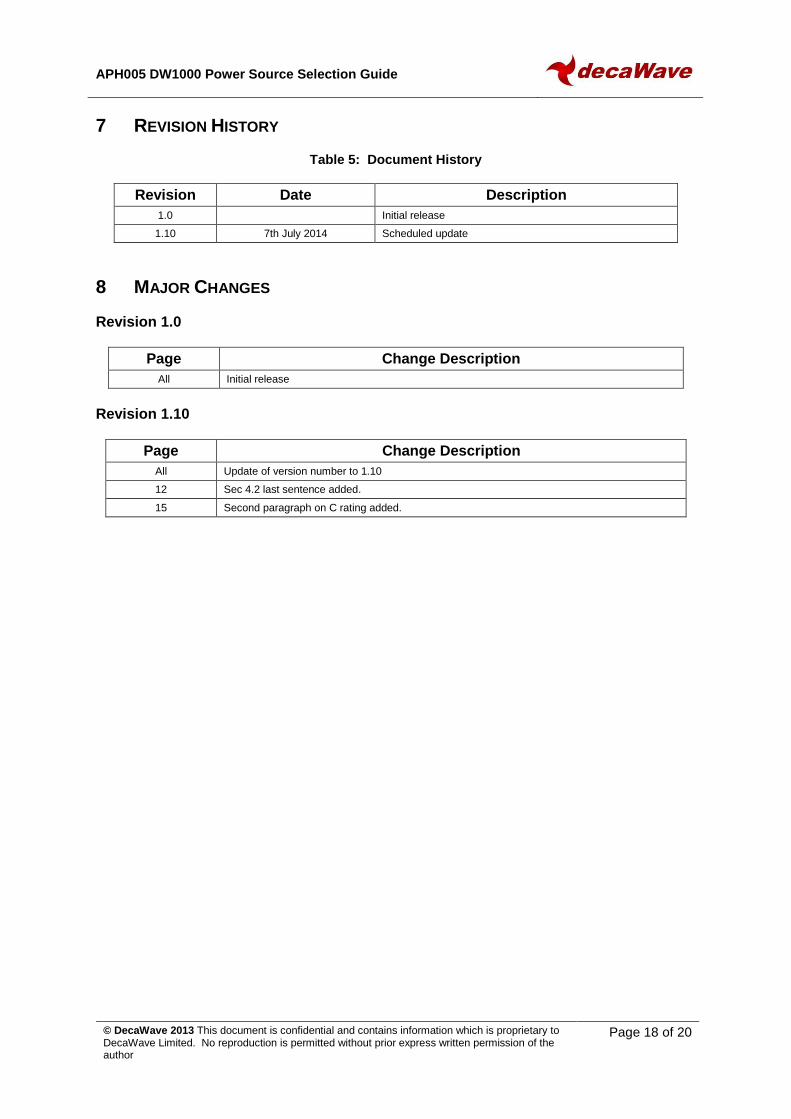
7 REVISION HISTORY
Table 5: Document History
Revision Date Description
1.0 Initial release
1.10 7th July 2014 Scheduled update
8 MAJOR CHANGES
Revision 1.0
Page Change Description
All Initial release
Revision 1.10
Page Change Description
All Update of version number to 1.10
12 Sec 4.2 last sentence added.
15 Second paragraph on C rating added.

APH005 DW1000 Power Source Selection Guide
© DecaWave 2013 This document is confidential and contains information which is proprietary to DecaWave Limited. No reproduction is permitted without prior express written permission of the author
Page 19 of 20
9 REFERENCES
9.1 Listing
Reference is made to the following documents in the course of this Application Note: -
Table 6: Table of References
Ref Author Date Version Title
[1] DecaWave 2.00 DW1000 Datasheet

APH005 DW1000 Power Source Selection Guide
© DecaWave 2013 This document is confidential and contains information which is proprietary to DecaWave Limited. No reproduction is permitted without prior express written permission of the author
Page 20 of 20
10 ABOUT DECAWAVE
DecaWave is a pioneering fabless semiconductor company whose flagship product, the DW1000, is a complete, single chip CMOS Ultra-Wideband IC based on the IEEE 802.15.4-2011 UWB standard. This device is the first in a family of parts that will operate at data rates of 110 kbps, 850 kbps and 6.8 Mbps. The resulting silicon has a wide range of standards-based applications for both Real Time Location Systems (RTLS) and Ultra Low Power Wireless Transceivers in areas as diverse as manufacturing, healthcare, lighting, security, transport, inventory & supply chain management. Further Information For further information on this or any other DecaWave product contact a sales representative as follows: - DecaWave Ltd Adelaide Chambers Peter Street Dublin 8 t: +353 1 697 5030 e: [email protected] w: www.decawave.com