application characteristics using deep cement mixing
TRANSCRIPT

ISGSR2007 First International Symposium on Geotechnical Safety & Risk Oct. 18~19, 2007 Shanghai
Tongji University, China Application Characteristics using Deep Cement Mixing Method in Various Soil conditions T. S. Yang Kimpo College, Kimpo, Korea G. H. Jeong DongA Geological Co., Ltd., Busan, Korea J. D. Koo Korea Institute of Constrution Technology, Goyang, Korea ABSTRACT: Applications of the DCM(Deep Cement Mixing) Method domestically since 1985 have been employed to improve stability, increase bearing capacity, and reduce settlement of several structures in land and sea area. The construction efficiency of DCM method in the stiff soil layer largely depends on the penetration characteristics of blade attached to the DCM mixing tool. A spiral mixing blade has been revised to increase the construction efficiency of DCM method in the stiff soils.
Penetration characteristics of spiral blades building a self-supported DCM wall in the stiff soil layer were evaluated through trial constructions in Gimhae, Incheon, or keywalls in Gunjang areas. Application phenomena and economical efficiency should be considered to determine the critical depth because the penetration efficiency may be decreased in the various soil layers of land or sea area. In this paper it is for the relationship of N value and penetration rate to decrease errors happened owing to uncertainties of influence factors in different soil conditions through statistical analysis approach. Reliability concept in this paper is to do the safety evaluation and increase the effectiveness of construction equipment for the determined value of penetration rate considering the coefficient of variation of depth- penetration rate data including penetration time in different soil conditions , which results of this study is very useful for design stage.
1 INTRODUCTION
Probability-based design method is to identify the designing method in which capacity meets the standards is up to the designer. Europe uses a performance-oriented design that is primarily based on reliability design as opposed to safety factor or allowable stress design method. Therefore, it is necessary to pursue an international conformity to standards in terms of harbor technology standards.
In this paper, we will introduce the domestic and overseas trends concerning the DCM method of structures, the necessity of international conformity to harbor standards, the response of ISO in harbor areas, the revision goals of harbor standards, and code calibration of dike design.
The parameter for calculating structure in terms of geotechnical engineering is always chosen by the designer. However, the design criteria or design standards do not cover how a parameter is chosen, and how much the calculated parameter should be applied. This shows that determining the measured value is not only very important, but also choosing the determined value is difficult to define. In Eurocode 7, the measured value, derived value, characteristic value and design value are mentioned while acquiring the design value of the parameter in terms of foundation engineering.
The geotechnical parameter figure usually entails a result that carefully calculates the figure that affects the occurrence of limit states. Statistics-wise, it can be defined as a figure in which the probability of the figure controlling the occurrence of limits does not exceed 5%. Therefore, the figure must be decided upon during the actual designing with certain limits and uncertainty of foundation in consideration.
617

It is good to have as much data as possible because the design of an uneconomical building could occur if the change is considered big due to insufficient data on experiments. Also, all data must be filtered to reach a high level of credibility.
Deep cement mixing (DCM) technologies have been applied to build self-supported earth retaining walls to support underground excavation works. For the self-supported DCM wall to assure the self-supporting ability, DCM columns should be penetrated into the stiff layer to derive a sufficient passive resistance against the lateral forces acing on the wall. However, a conventional mixing blade attached to the DCM mixing tool was originally developed for soft soils and therefore the penetration efficiency of conventional blades is significantly lowered in the stiff layer. The construction efficiency of DCM method in the stiff soil layer largely depends on the penetration characteristics of blade attached to the DCM mixing tool. A spiral mixing blade has been revised to increase the construction efficiency of DCM method in the stiff layer while building a self-supported DCM wall in Incheon area. Trial constructions have been carried out to evaluate the penetration characteristics of new blades both in Gimhae, Incheon, and Gunjang areas. Penetration characteristics of spiral blades employed to build a self-supported DCM wall in the stiff soil layer are presented in terms of soil types, their stiffness, and N value in land or sea area. In this paper it is for the relationship of N value and penetration rate to decrease errors happened owing to uncertainties of influence factors in different soil conditions. Through statistical analysis approach, the safety evaluation and the effectiveness of construction equipment is tried to find the determined value of penetration rate considering the depth- penetration rate data by measured values in different soil conditions.
2 APPLICATIONS OF DCM METHOD IN LAND AND SEA
The DCM method was developed to improve soft foundation soils or to build an earth retaining wall to support excavation works. It is an in situ soil treatment and improvement technology whereby the ground is blended with cementitious or other materials to form a vertical stiff column in the ground. These materials are referred to as “binders” and can be introduced in a slurry or dry form.
After Scandinavian countries and Japan independently developed since the late 1960’s, a combination of lime and cement are extensively used in the deep mixing method in Sweden and Finland. Japanese CDIT (Coastal Development Institute of Technology) developed a DCM method in which binding materials are introduced in the form of slurry. The deep mixing method utilizes such agents as quicklime, slaked lime, cement, slag, fly ash or a combination of these agents. Recently, the deep mixing method is used to a various construction projects in Asian countries, also.
2.1 Domestic trends for land application DCM method was first introduced as a SEC(Special Earth Concrete) method for the construction of Su-Young waste water treatment plant in 1985 and it was applied to build a self-supported earth retaining wall and a foundation in Korea.
The treatable depth with the DCM method largely depends on the capacity of equipment. The earlier version of equipment, 110P, could improve soils up to the depth of 20~25m. However, a modern version of equipment, 170P, can improve soils up to the depth of 35~37m. In the introductory stage of DCM method in Korea, a two-shaft mixing tool (φ 1,000×2rod) was used for foundation applications whereas a three-shaft mixing tool ( φ 550× 3rod) was employed for the construction of earth retaining walls. Afterwards, a four-shaft mixing tool (φ 1,000 ×4rod) has been developed to meet a demand for a variety of improving configuration. The four-shaft mixing tool has several advantages over the two-shaft mixing tool. They include the higher construction efficiency due to a wider improving area, a better mixing efficiency and a higher stability of earth retaining wall due to a better overlapping. 2.2 Domestic trends for sea application First applications of DCM method in sea level goes to Sammi Steel Construction site to build new revetment of Changwon city in 1988. For this work, combinated ship which pile drives for land are on
618
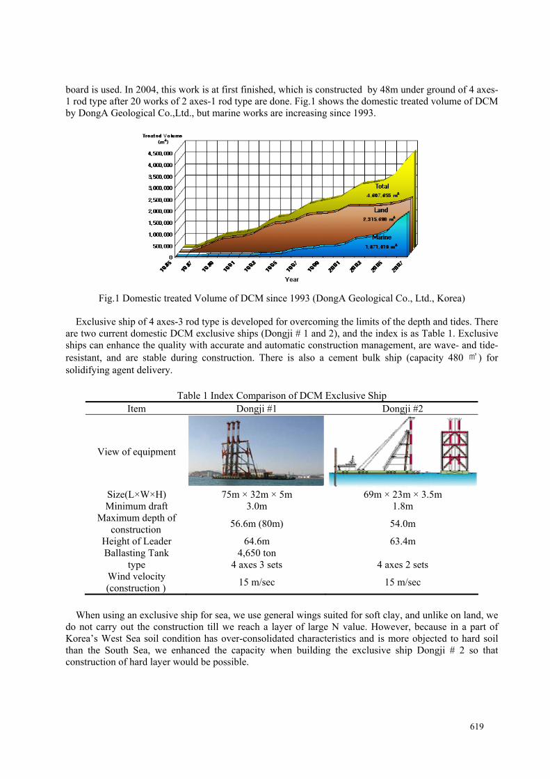
board is used. In 2004, this work is at first finished, which is constructed by 48m under ground of 4 axes-1 rod type after 20 works of 2 axes-1 rod type are done. Fig.1 shows the domestic treated volume of DCM by DongA Geological Co.,Ltd., but marine works are increasing since 1993.
Fig.1 Domestic treated Volume of DCM since 1993 (DongA Geological Co., Ltd., Korea)
Exclusive ship of 4 axes-3 rod type is developed for overcoming the limits of the depth and tides. There
are two current domestic DCM exclusive ships (Dongji # 1 and 2), and the index is as Table 1. Exclusive ships can enhance the quality with accurate and automatic construction management, are wave- and tide-resistant, and are stable during construction. There is also a cement bulk ship (capacity 480 ㎥) for solidifying agent delivery.
Table 1 Index Comparison of DCM Exclusive Ship
Item Dongji #1 Dongji #2
View of equipment
Size(L×W×H) 75m × 32m × 5m 69m × 23m × 3.5m Minimum draft 3.0m 1.8m
Maximum depth of construction 56.6m (80m) 54.0m
Height of Leader 64.6m 63.4m Ballasting Tank 4,650 ton
type 4 axes 3 sets 4 axes 2 sets Wind velocity (construction ) 15 m/sec 15 m/sec
When using an exclusive ship for sea, we use general wings suited for soft clay, and unlike on land, we
do not carry out the construction till we reach a layer of large N value. However, because in a part of Korea’s West Sea soil condition has over-consolidated characteristics and is more objected to hard soil than the South Sea, we enhanced the capacity when building the exclusive ship Dongji # 2 so that construction of hard layer would be possible.
619

3 Case Studies of DCM Method
3.1 Plan of self-supported DCM wall The subsurface soil at the site of Hak-ik waste water treatment facility in Incheon consists of reclaimed soil, alluvial clay, weathered soil and weathered rock. A self-supported DCM wall was planned to be constructed as an excavation support system as shown in Fig.2. A number of DCM columns were determined based on the excavation depth to assure the stability of the excavation work.
EL(-)0.650
EL(+)4.800
EL(+)1.900
ZONE B
EL(-)13.700
Soft Clay
Stiff Clay
ZONE E
φ1000, 12Rows
H=30.6 m
H-PILE (H-300x300x10x15)
C.T.C 1.8m H=30.6m
(N≤6)
(N>6)
φ1000, 6 Rows
H=22.0 m
H-PILE (H-300x300x10x15)
C.T.C 3.6m H=22.0m
EL(-)18.700
EL(±)0.000
Weathered Soil
EL(-)13.100
EL(-)18.100
EL(±)0.000
EL(+)2.500
EL(+)5.000
Reclaimed Layer
EL(+)2.500
(Tre
ate
d C
olu
mn)
(Tre
ate
d C
olu
mn)
1:2.5 EL(+)5.000
1:2.5
EL(+)5.000 EL(+)5.000
1:2.5
EL(-)10.870 22000
30600
12770
17830
10001000 5950
6950
5450
16550
3100
100013270
14270
Non-treated Hole
Soft Clay
Stiff Clay
(N≤6)
(N>6)
Weathered Soil
Reclaimed Layer
Fig.2 Cross sectional view of self-supported DCM wall
3.2 Characteristics of subsurface soils Based on the standard penetration test performed during the subsurface investigation, the N-value of upper reclaimed layer was less than 20/30 and showed a wide scatter. The N-value of alluvial clay layer ranged 1/30~50/30, and the N-value of weathered soil and rock exceeded 50. The ground water table is located 0~7.9m below the ground surface.
Incomplete DCM columns were found in the stiff clay and weathered soil layers during the construction of DCM wall. The uncompleted thickness ranged 0.1~5.0m. A reinforcement was planned to assure the stability of DCM wall as presented in Fig.3. In addition, two types of mixing blades were revised to facilitate a penetration into the stiff soil layer.
EL(-)7.000
1:2.5
EL(±)0.000
EL(+)5.000
φ1000, 6 Rows
H=22.0 m
H-PILE (H-300x300x10x15)
C.T.C 2.7m H=22.0m
EL(-)12.000
EL(-)17.000
EL(±)0.000
EL(+)2.500
EL(+)5.000
1:2.5
EL(-)7.000
1:2.5
EL(±)0.000
EL(+)6.500
φ1000, 6Rows
H=22.0 m
H-PILE (H-300x300x10x15)
C.T.C 2.7m H=22.0m
EL(-)12.000
EL(-)17.000
EL(±)0.000
EL(+)2.500
EL(+)6.500
1:2.5
Incomplete Zone
EL(-)7.000
1:2.5
EL(±)0.000
EL(+)6.500
φ1000, 6 Rows
H=22.0 m
H-PILE (H-300x300x10x15)
C.T.C 2.7m H=22.0m
EL(-)12.000
EL(-)17.000
EL(±)0.000
EL(+)2.500
EL(+)6.500
1:2.5
Reinforcing
Original Design After Construction Reinforcement
ZONE-A(Final Excavation Depth 7.0m)
DCM Column
Soft Clay
Stiff Clay
(N≤6)
(N>6)
Weathered Soil
Reclaimed Layer
(Tre
ate
d C
olu
mn)
Non-treated Hole
22000
7000
15000
5000
10007500
8500
22000
7000
15000
6400~
6500
10007500
8500
17100~
19500
7000
15000
6400~
6500
10007500
8500
(Tre
ate
d C
olu
mn)
22000
(Tre
ate
d C
olu
mn)
Non-treate
d H
ole
Non-treate
d H
ole
Soft Clay
Stiff Clay
(N≤6)
(N>6)
Weathered Soil
Reclaimed Layer
Soft Clay
Stiff Clay
(N≤6)
(N>6)
Weathered Soil
Reclaimed Layer
Fig.3 Cross sectional view of reinforcement in the stiff soil layer
620

3.3 Data Classfication for Statistical Approach Applied Based on the standard penetration test many data are used for this study. First of all in the land and sea area data contains soil layer thickness, N value, penetration rate, penetration time, which get 65 and 76 points of depth-penetration relationship in sandy and clayey layers by the in-situ standard penetration test in the land area. In case of marine area in clayey layers by the in-situ standard penetration test, we could apply 25 points of depth-penetration rate relationship, total 166points.
In this paper it is for the relationship of N value and penetration rate to decrease errors happened owing to uncertainties of influence factors in different soil conditions through statistical analysis approach. Using reliability concept is to do the safety evaluation and increase the effectiveness of construction equipment such as deep cement mixing method for the determined value of penetration rate considering the coefficient of variation of depth- penetration rate data including penetration time in different soil conditions.
4 Penetration Phenomena of Mixing Blades to Penetrate into Stiff Soils
4.1 Penetration Characteristics of Conventional Mixing Blade 4.1.1 Conventional mixing blade in soft soils Mixing blades used in domestic DCM methods were developed for an application to the soft clay layer and employed a two-stroke type in which water is introduced in the process of penetration. In recent days, a one-stroke type where slurry is introduced and mixed both in the process of penetration and retrieval is mainly employed. The one-stroke method is proved to be effective for a quality control. Fig.8(a) shows a conventional mixing blade employed in soft clayey soils.
Fig.4 and 5 show penetration characteristics of one-stroke DCM mixing tool equipped with a conventional mixing blade employed to form DCM columns with a diameter of 1,000mm in Gimhae area located in the southern coastal area over which a thick soft clay deposit is distributed. A four-shaft mixing tool, 135P was employed in the project. Time required for the penetration into the reclaimed layer and the sand layer with greater N-values was appeared to be irregular and long whereas the penetration time in the silty clay layer was consistent. It took 16~19 minutes to penetrate the whole design depth of 21m in Fig.4.
Penetration Time (Min)
0 5 10 15 20 25 300
5
10
15
20
25
L-0.83-600 M-0.83-600O-0.83-600J-0.72-520U-0.72-520V-0.72-520P-0.56-400R-0.56-400S-0.56-400
Reclaimed Layer
Soil Profile
Silty Clay
Sand
Sandy Gravel
Weathered Soil
-1.3m
-17.3m
-22.0m
-23.3m
N-Value
0 10 20 30
Depth(G
.L(-
) : m)
0
5
10
15
20
25
P e n etratio n R ate(m /m in )
0 .0 0 .5 1 .0 1 .5 2 .0 2 .5 3 .00
5
1 0
1 5
2 0
2 5
L- 0 .8 3 - 6 0 0 M - 0 .8 3 - 6 0 0O - 0 .8 3 - 6 0 0J- 0 .7 2 - 5 2 0 U - 0 .7 2 - 5 2 0V - 0 .7 2 - 5 2 0P - 0 .5 6 - 4 0 0 R - 0 .5 6 - 4 0 0 S - 0 .5 6 - 4 0 0
R e c laim atio n
S o il P ro file
S ilty C lay
S an d
S an d G rave l
W e ath e re d S o il
- 1 .3 m
- 17.3m
- 22 .0m
- 23.3m
N - value
0 10 2 0 30
Depth(G
.L(-) : m)
0
5
1 0
1 5
2 0
2 5 Fig.4 Penetration time-Depth in Gimhae Fig.5 Penetration rate-Depth in Gimhae
Fig.5 shows a variation of penetration rate with depth. The penetration rate was appeared to be slower
in reclaimed soil and dense sand layers than in silty clay layer. The penetrating rate appeared to be almost constant in the silty clay layer. The slower penetration rate recorded in the reclaimed-soil layer may be attributed to larger particles mixed in the reclaimed soil. However, the penetration rate decreased because it requires a longer mixing time to assure a complete formation of DCM column end in the dense sand layer. The penetration rate was appeared to be 1.3~1.9m/min in the soft silty clay layer.
621
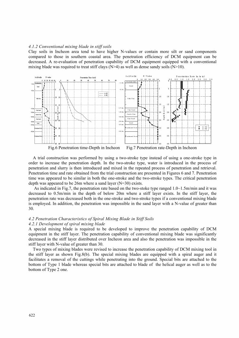
4.1.2 Conventional mixing blade in stiff soils Clay soils in Incheon area tend to have higher N-values or contain more silt or sand components compared to those in southern coastal area. The penetration efficiency of DCM equipment can be decreased. A re-evaluation of penetration capability of DCM equipment equipped with a conventional mixing blade was required to treat stiff clays (N>4) as well as dense sandy soils (N>10).
Penetration Time (min)
0 10 20 30 40 50 60 70 800
5
10
15
20
25
30
35
40
A-53A-95
Reclaimation
Soil Profile
Silty Clay
Sand
W eathered Rock
W eathered Soil
-1.3m
-17.3m
-19.8m
-22.8m
N-value
0 10 20 30 40 50
Depth (G.L(-
):m)
0
5
10
15
20
25
30
35
40
-5.7m
-25.8m
-32.2m
Sandy Clay
Clay Sand
Sand
Clay Sand
-27.8m
P e n e tra tio n R a te (m /m in )
0 .0 0 .5 1 .0 1 .5 2 .0 2 .5 3 .0 3 .50
5
1 0
1 5
2 0
2 5
3 0
3 5
4 0
A - 5 3A - 9 5
R e c la im a tio n
S o il P ro file
S ilty C la y
S a n d
W e a th e re d R o c k
W e a th e re d S o il
- 1 .3 m
- 1 7 .3 m
- 1 9 .8 m
- 2 2 .8 m
N - V a lu e
0 1 0 2 0 3 0 4 0 5 0
Depth (G.L(-
):m)
0
5
1 0
1 5
2 0
2 5
3 0
3 5
4 0
- 5 .7 m
- 2 5 .8 m
- 2 7 .8 m
S a n d y C la y
C la y S a n d
S a n d
C la y S a n d
- 3 2 .2 m
Fig.6 Penetration time-Depth in Incheon Fig.7 Penetration rate-Depth in Incheon
A trial construction was performed by using a two-stroke type instead of using a one-stroke type in
order to increase the penetration depth. In the two-stroke type, water is introduced in the process of penetration and slurry is then introduced and mixed in the repeated process of penetration and retrieval. Penetration time and rate obtained from the trial construction are presented in Figures 6 and 7. Penetration time was appeared to be similar in both the one-stroke and the two-stroke types. The critical penetration depth was appeared to be 26m where a sand layer (N=30) exists.
As indicated in Fig.7, the penetration rate based on the two-stoke type ranged 1.0~1.5m/min and it was decreased to 0.5m/min in the depth of below 20m where a stiff layer exists. In the stiff layer, the penetration rate was decreased both in the one-stroke and two-stroke types if a conventional mixing blade is employed. In addition, the penetration was impossible in the sand layer with a N-value of greater than 30.
4.2 Penetration Characteristics of Spiral Mixing Blade in Stiff Soils 4.2.1 Development of spiral mixing blade A special mixing blade is required to be developed to improve the penetration capability of DCM equipment in the stiff layer. The penetration capability of conventional mixing blade was significantly decreased in the stiff layer distributed over Incheon area and also the penetration was impossible in the stiff layer with N-value of greater than 30.
Two types of mixing blades were revised to increase the penetration capability of DCM mixing tool in the stiff layer as shown Fig.8(b). The special mixing blades are equipped with a spiral auger and it facilitates a removal of the cuttings while penetrating into the ground. Special bits are attached to the bottom of Type 1 blade whereas special bits are attached to blade of the helical auger as well as to the bottom of Type 2 one.
622
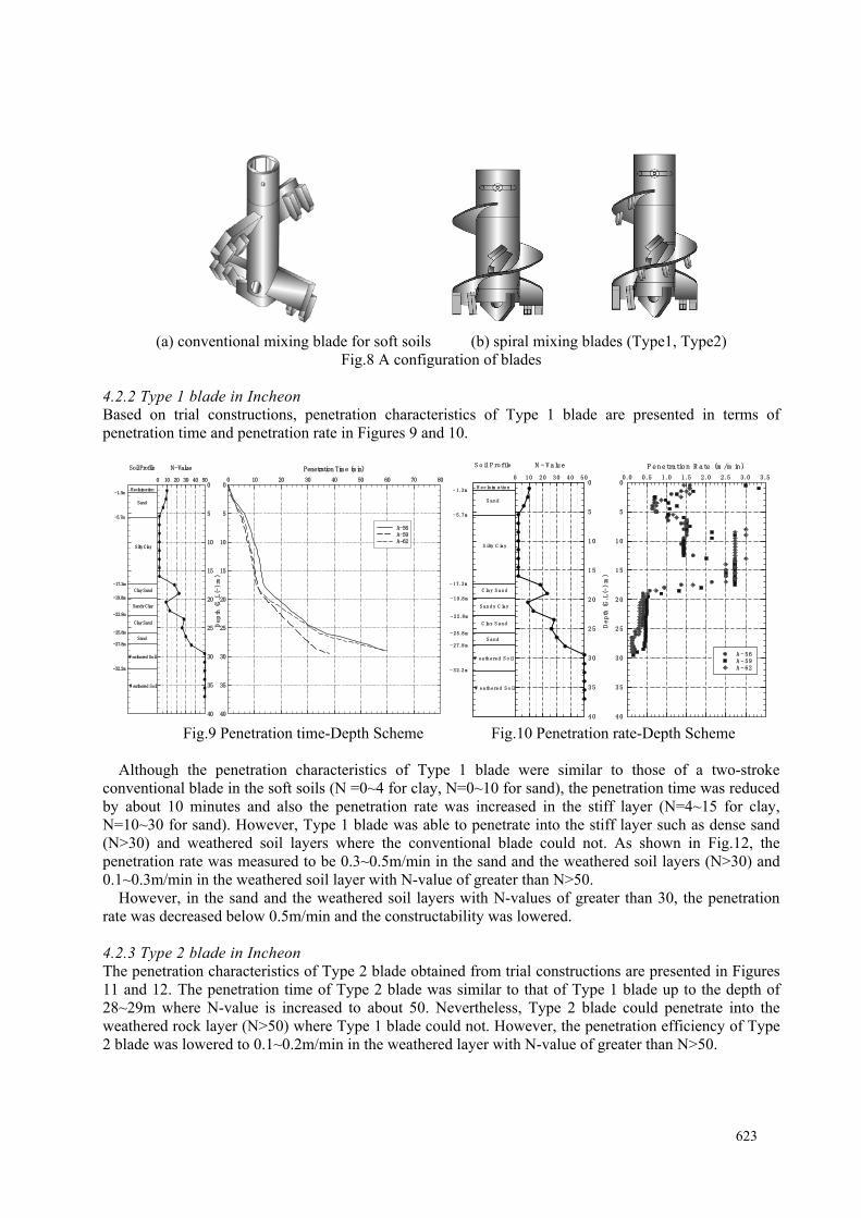
(a) conventional mixing blade for soft soils (b) spiral mixing blades (Type1, Type2) Fig.8 A configuration of blades
4.2.2 Type 1 blade in Incheon Based on trial constructions, penetration characteristics of Type 1 blade are presented in terms of penetration time and penetration rate in Figures 9 and 10.
Penetration Tim e (m in)
0 10 20 30 40 50 60 70 800
5
10
15
20
25
30
35
40
A-56A-59A-62
Reclaim ation
Soil Profile
Silty Clay
Sand
W eathered Soil
W eathered Soil
-1.3m
-17.3m
-19.8m
-22.8m
N-Value
0 10 20 30 40 50
Depth (G.L(-
):m)
0
5
10
15
20
25
30
35
40
-5.7m
-25.8m
-32.2m
Sandy Clay
Clay Sand
Sand
Clay Sand
-27.8m
P enetratio n R ate (m /m in)
0.0 0.5 1.0 1.5 2.0 2.5 3.0 3.50
5
10
15
20
25
30
35
40
A - 56A - 59A - 62
- 1.3m
- 17.3m
- 19.8m
- 22.8m
0 10 20 30 40 50
Depth (G.L(-
):m)
0
5
1 0
15
20
25
30
35
40
- 5.7m
- 25.8m
- 27.8m
- 32.2m
R eclaim atio n
S o il P ro file
S ilty C lay
S and
W eathered S o il
W eathered S o il
N - V alue
S and y C lay
C lay S and
S and
C lay S and
Fig.9 Penetration time-Depth Scheme Fig.10 Penetration rate-Depth Scheme
Although the penetration characteristics of Type 1 blade were similar to those of a two-stroke conventional blade in the soft soils (N =0~4 for clay, N=0~10 for sand), the penetration time was reduced by about 10 minutes and also the penetration rate was increased in the stiff layer (N=4~15 for clay, N=10~30 for sand). However, Type 1 blade was able to penetrate into the stiff layer such as dense sand (N>30) and weathered soil layers where the conventional blade could not. As shown in Fig.12, the penetration rate was measured to be 0.3~0.5m/min in the sand and the weathered soil layers (N>30) and 0.1~0.3m/min in the weathered soil layer with N-value of greater than N>50.
However, in the sand and the weathered soil layers with N-values of greater than 30, the penetration rate was decreased below 0.5m/min and the constructability was lowered.
4.2.3 Type 2 blade in Incheon The penetration characteristics of Type 2 blade obtained from trial constructions are presented in Figures 11 and 12. The penetration time of Type 2 blade was similar to that of Type 1 blade up to the depth of 28~29m where N-value is increased to about 50. Nevertheless, Type 2 blade could penetrate into the weathered rock layer (N>50) where Type 1 blade could not. However, the penetration efficiency of Type 2 blade was lowered to 0.1~0.2m/min in the weathered layer with N-value of greater than N>50.
623

Penetration Tim e(m in)
0 20 40 60 80 100 120 140 160 180 200 220 2400
5
10
15
20
25
30
35
40
B-1 B-3B-4B-5
-1.4m
-17.7m
-21.8m
-24.8m
0 10 20 30 40 50
Depth (G.L(-
):m)
0
5
10
15
20
25
30
35
40
-4.8m
-27.5m
-30.8m
Reclaim ation
Silty Clay
Sand
W eathered Soil
W eathered Soil
Sandy Clay
Sand
Clay Sand
Soil Profile N-Value P e n e tra tio n T im e (m /m in )
0 .0 0 .5 1 .0 1 .5 2 .0 2 .5 3 .0 3 .50
5
1 0
1 5
2 0
2 5
3 0
3 5
4 0
B - 1 B - 3B - 4B - 5
- 1 .4 m
- 1 7 .7 m
- 2 1 .8 m
- 2 4 .8 m
0 1 0 2 0 3 0 4 0 5 0
Depth (G.L(-
):m)
0
5
1 0
1 5
2 0
2 5
3 0
3 5
4 0
- 4 .8 m
- 2 7 .5 m
- 3 0 .8 m
R e c la im a tio n
S o il P ro file
S ilty C la y
S a n d
W e a th e re d S o il
W e a th e re d S o il
N - V a lu e
S a n d y C la y
S a n d
C la y S a n d
Fig.11 Penetration time-Depth Scheme Fig.12 Penetration rate-Depth Scheme
4.3 Correlation of Penetration Characteristics The penetration rates of various blades, measured from trial constructions, were analyzed based on N-value to evaluate the penetration characteristics of DCM equipment depending on soil type and their stiffness. Their correlations are presented in Figures 13 through 14. N-values of greater than 50/30 were converted to the number of blows for the 30 cm of penetration.
A correlation of penetration rate and N-value obtained from both Gimhae and Incheon areas is presented in Fig.13. As indicated in Fig.13, the penetration rate tends to decrease as the N-value increases.
After eliminating the converted N-value of greater than 100, a correlation of penetration rate and the converted N-value of soil layers to which the DCM method can be applied is presented in Fig.14. The penetration rate tends to decrease as the N-value increases. The scatter of correlation tends to be decreased as the converted N-value increases.
Fig.13 Correlation of N-Value and Penetration rate
Fig.14(a) shows a correlation of penetration rate and N-value in the clay layer. The penetration rate
tends to decrease as the N-value increases. The average penetration rate was about 1.0m/min for the N-value of 0~4 but it was decreased to 0.50m/min for the N-value of 4~15. The average penetration rate was appeared to be slower than 0.3m/min for the N-value of greater than 15.
624

A correlation of penetration rate and N-value in sand layer is shown in Fig.14(b). The average penetration rate was 1.0m/min for the N-value of 0~10 and it was decreased to 0.5m/min for the N-value of 10~30. For the N-value of greater than 30, the average penetration rate decreased below 0.3m/min.
N-Value
1 10 100
Pene
trat
ion
Rat
e (m
/min
)
0.01
0.1
1
10K-S - C (C-1) I -R - C (C-1)I -H -C (C-1)I -H -C (C-2)I -H - C (S1-2)I -H -C (S2-2)
y = 10(-0.017 x + log2.5)
y = 10(-0.017 x + log0.3)
N-Value1 10 100
Pene
trat
ion
Rat
e (m
/min
)
0.01
0.1
1
10K-S - S (C-1)I -R - S (C-1)I -H - S (C-1)I -H - S (C-2)I -H - S (S1-2)I -H - S (S2-2)
y = 10(-0.017 x + log2.5)
y = 10(-0.017 x + log0.3)
(a) Clay (b) Sand
Fig.14 Correlation of N-Value and Penetration rate
In Japan, a standard penetration rate of 1.0m/min is established as a criterion to select a soil type where an application of DCM is possible. Based on Japanese criterion, DCM can be applied to clay soils with an N-value of less than 4 and to sandy soils with an N-value of less than 8. Penetration rates obtained from trial constructions fall within Japanese criterion.
Penetration rates in the clay layer were appeared to be slower than those in the sand layer which has a similar N-value.
4.4 Cases of Marine construction in Gunjang areas 4.4.1 Relationship between Penetration rate and depth Fig.15 shows penetration characteristics of one-stroke DCM mixing tool equipped with a conventional mixing blade employed in Gunjang over which a soft clay deposit is distributed. According to Fig.15 penetration rate with depth is varied. The penetration rate was appeared to be faster in reclaimed soil and slower in silty clay layer.
625
Penetration rate(m/min) vs Depth(m) : NH-9Penetration rate(m/min)
0.0 0.5 1.0 1.5 2.0 2.5 3.0 3.510
15
20
25
30
35
KC-12 (1 Stroke)KC-13 (1 Stroke)KC-14 (1 Stroke - Retrieval)
Soil Propile
Seawater
Weathered Soil
-10.0m
-16.0m
-23.6m
N - Value
0 10 20 30 40 50
Dep
th (D
L.(-
):m
)
10
15
20
25
30
35
Sandy Silt
Dredging
Penetration rate vs Depth : NH-16Penetration rate (m/min)
0.0 0.5 1.0 1.5 2.0 2.5 3.0 3.510
15
20
25
30
35
EZ-12 (1 Stroke)EZ-13 (2 Stroke)EZ-14 (1 Stroke - Retrieval)FA-13 (2 Stroke)FA-14 (1 Stroke - Retrieval)FB-13 (2 Stroke)FB-14 (1 Stroke - Retrieval)FC-13 (2 Stroke)FC-14 (1 Stroke - Retrieval)
Soil Propile
Seawater
Weathered Soil
-10.0m
-18.0m
-26.6m
N - Value
0 10 20 30 40 50
Dep
th (D
L.(-
):m
)
10
15
20
25
30
35
Silty Clay
Dredging
Fig.15 Penetration rate-Depth Relationship
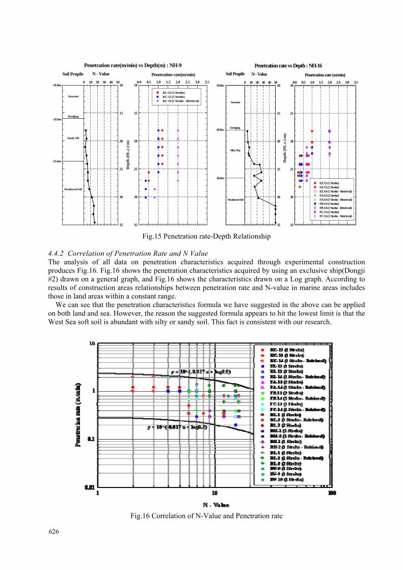
4.4.2 Correlation of Penetration Rate and N Value The analysis of all data on penetration characteristics acquired through experimental construction produces Fig.16. Fig.16 shows the penetration characteristics acquired by using an exclusive ship(Dongji #2) drawn on a general graph, and Fig.16 shows the characteristics drawn on a Log graph. According to results of construction areas relationships between penetration rate and N-value in marine areas includes those in land areas within a constant range.
We can see that the penetration characteristics formula we have suggested in the above can be applied on both land and sea. However, the reason the suggested formula appears to hit the lowest limit is that the West Sea soft soil is abundant with silty or sandy soil. This fact is consistent with our research.
Fig.16 Correlation of N-Value and Penetration rate
626

4.5 Comparisons of Penetration Characteristics applied in Land and Sea (Summary) 4.5.1 Correlation of Penetration rate and N value The analysis of all data on penetration characteristics got from land and marine through experimental construction are shown in Fig.17. Fig.17 shows mixed points of the sand and clay layers related to penetration rate on log graph. When land-conventional in Fig.17 stands for penetration works using conventional blade in the land area, land-special stands for penetration works using revised blade(Type 1, Type 2) in the land area.
N -Value
1 10 100
Pene
trat
ion
Rat
e (m
/min
)
0 .01
0.1
1
10Land - C onventionalLand - SpecialM arine - Conventional
y = 10(-0.017 x + log2.5)
y = 10(-0.017 x + log0.3)
Fig.17 Correlation of N-Value and Penetration rate (Land+Marine)
Fig.18 shows N value points of the clay layers only related to penetration rate on log graph both in land
and marine area. Fig.19 shows N value points of the sand layers only related to penetration rate on log graph also.
N-Value
1 10 100
Pene
trat
ion
Rat
e (m
/min
)
0.01
0.1
1
10Land - ConventionalLand - SpecialMarine - Conventional
y = 10(-0.017 x + log2.5)
y = 10(-0.017 x + log0.3)
Fig.18 Penetration rate-N Value(Land+Marine, Clay)
627
N-Value1 10 100
Pene
trat
ion
Rat
e (m
/min
)
0.01
0.1
1
10Land - ConventionalLand - SpecialMarine - Conventional
y = 10(-0.017 x + log2.5)
y = 10(-0.017 x + log0.3)
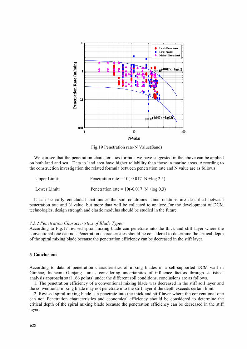
Fig.19 Penetration rate-N Value(Sand)
We can see that the penetration characteristics formula we have suggested in the above can be applied
on both land and sea. Data in land area have higher reliability than those in marine areas. According to the construction investigation the related formula between penetration rate and N value are as follows
Upper Limit: Penetration rate = 10(-0.017 N +log 2.5) Lower Limit: Penetration rate = 10(-0.017 N +log 0.3)
It can be early concluded that under the soil conditions some relations are described between
penetration rate and N value, but more data will be collected to analyze.For the development of DCM technologies, design strength and elastic modulus should be studied in the future.
4.5.2 Penetration Characteristics of Blade Types According to Fig.17 revised spiral mixing blade can penetrate into the thick and stiff layer where the conventional one can not. Penetration characteristics should be considered to determine the critical depth of the spiral mixing blade because the penetration efficiency can be decreased in the stiff layer.
5 Conclusions
According to data of penetration characteristics of mixing blades in a self-supported DCM wall in Gimhae, Incheon, Gunjang areas considering uncertainties of influence factors through statistical analysis approach(total 166 points) under the different soil conditions, conclusions are as follows.
1. The penetration efficiency of a conventional mixing blade was decreased in the stiff soil layer and the conventional mixing blade may not penetrate into the stiff layer if the depth exceeds certain limit.
2. Revised spiral mixing blade can penetrate into the thick and stiff layer where the conventional one can not. Penetration characteristics and economical efficiency should be considered to determine the critical depth of the spiral mixing blade because the penetration efficiency can be decreased in the stiff layer.
628

3. For the safety evaluation and increasing the effectiveness of construction equipment, the determined value of penetration rate could be considered the coefficient of variation of depth- penetration rate data including penetration time in different soil conditions. The characteristics formula below can be applied on both land and sea. Data in land area have higher reliability than those in marine one. According to the construction investigation the related formula between penetration rate and N value by regression analysis are as follows
Upper Limit: Penetration rate = 10(-0.017 N +log 2.5)
Lower Limit: Penetration rate = 10(-0.017 N +log 0.3)
4. For the development of DCM technologies and safety evaluation, design strength and elastic modulus should be studied in the future . REFERENCE Jeong Gyunghwan, Bae Jonggyeon et al., 2006. Study on Development of Special Rotary Wing of DCM in Stiff Soil . Proceedings of Technical Committee on Dredging and Reclaiming, Korea Geotechnical Society, 2006, Korea, 193~200. (in Korean) Yang Taeseon, Jeong Gyunghwan, Yeo Bonggu, Lee Sangsoo, 2000. A Study on Design Strength and Elastic Modulus using Deep Cement Mixing Method, Proceedings of Fall Conference of Korea Society of Civil Engineers, 2000, Korea, 193~200. (in Korean) Costal Development Institute of Technology, 2002, The Deep Cement Mixing Method(Principal Design And Construction), 2002 (in Japanese)
629

630