appendix a qa/qc procedures manual for base map
TRANSCRIPT

APPENDIX A
QA/QC PROCEDURES MANUAL FOR
BASE MAP MAINTENANCE SERVICES PROJECT
Prepared by Office of Mapping and Geographic Information
Loudoun County, VA

Table of Contents
QA Matrix ....................................................................................................................................................................... 5 A. QA/QC Procedures for Building Outlines/Polygons: ............................................................................................... 6 B. QA/QC Procedures for Transportation Polygons ...................................................................................................... 7 C. QA/QC Procedures for Hydrographic Polygons ..................................................................................................... 11 D. QA/QC Procedures for Drainage/Hydrographic arcs ............................................................................................. 13 E. QA/QC Procedures for Forestry Polygons .............................................................................................................. 17 F. QA/QC Procedures for Tree Points ......................................................................................................................... 18 G. QA/QC Procedures for Miscellaneous Cultural Polygons ...................................................................................... 20 H. QA/QC Procedures for Miscellaneous Cultural Arcs ............................................................................................. 23 I. QA/QC Procedures for Miscellaneous Cultural Points ............................................................................................ 25 J. QA/QC Procedures for Topographic Contours: ....................................................................................................... 27 K. QA/QC Procedures for Elevation Points ................................................................................................................ 29 L. QA/QC Procedures for Sidewalk Centerline (Optional) ......................................................................................... 31
QA/QC procedures for this planimetric and topographic Base Map Maintenance Services are generally two fold, software and visual. Software checked (S) Visual checked (V) Automated Report (R) Manual Report (M)
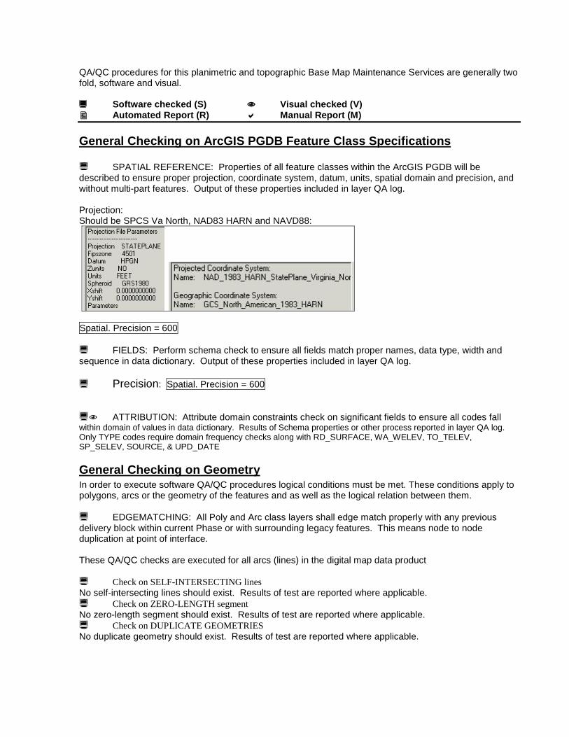
General Checking on ArcGIS PGDB Feature Class Specifications SPATIAL REFERENCE: Properties of all feature classes within the ArcGIS PGDB will be described to ensure proper projection, coordinate system, datum, units, spatial domain and precision, and without multi-part features. Output of these properties included in layer QA log. Projection: Should be SPCS Va North, NAD83 HARN and NAVD88:
Spatial. Precision = 600 FIELDS: Perform schema check to ensure all fields match proper names, data type, width and sequence in data dictionary. Output of these properties included in layer QA log. Precision: Spatial. Precision = 600 ATTRIBUTION: Attribute domain constraints check on significant fields to ensure all codes fall within domain of values in data dictionary. Results of Schema properties or other process reported in layer QA log. Only TYPE codes require domain frequency checks along with RD_SURFACE, WA_WELEV, TO_TELEV, SP_SELEV, SOURCE, & UPD_DATE
General Checking on Geometry In order to execute software QA/QC procedures logical conditions must be met. These conditions apply to polygons, arcs or the geometry of the features and as well as the logical relation between them. EDGEMATCHING: All Poly and Arc class layers shall edge match properly with any previous delivery block within current Phase or with surrounding legacy features. This means node to node duplication at point of interface. These QA/QC checks are executed for all arcs (lines) in the digital map data product Check on SELF-INTERSECTING lines No self-intersecting lines should exist. Results of test are reported where applicable. Check on ZERO-LENGTH segment No zero-length segment should exist. Results of test are reported where applicable. Check on DUPLICATE GEOMETRIES No duplicate geometry should exist. Results of test are reported where applicable.

ADJACENCY: Each polygon layer will be DISSOLVED on TYPE and secondary field (ELEV, SURFACE) if applicable. There shall be no discernable tile boundaries between features of like attribution. Certain polygon types must be surrounded by only certain polygon features. See individual Polygon rule 9 for additional details.
Attribute Adjacency check Poly features like bldgs, roads, water and forest cannot have neighboring features with the same attribute code. This prevents loss of courtyards, medians, islands, and clearings prior to the dissolve process
SLIVERS: Slivers between polygon features are not allowed, Rule 10 for all polygon layers OVERLAPPING: Overlapping between polygon features are not allowed. Exception to this rule includes Water Feature under bridge or anything in MiscPoly TYPE = 8. See individual feature rules #11 for additional details LOGICAL CHECKS: Various logical relationships must be maintained or prevented among feature classes and types. See individual feature rules #12 for additional details
General Checking on Attribution Feature TYPE or SURFACE codes are visually interpreted and must be within domain range. Additionally, elevation is photogrametrically derived and populated in ELEV fields for Water, SpotElev and Topo layers ELEVATION: Ensure proper decimal places, labeling display properties and value relationship among Water, SpotElev and Topo layers
General Checking on Layer-Specific Rules See individual layer rules for guidance on the following: PLACEMENT: Rules of placement apply to Spot Elevations, see Rule K14, (a-g) DIRECTIONALITY: Proper downhill directionality applies to Drainage arcs, see rule D15 CONNECTIVITY: Drainage network flow depends on connectivity, see rule D16 STORM WATER: Drainage integrates with and connects to external Storm Water data set according to special rules, see rule D17

QA Matrix This matrix is a quick look at which error checking processes apply to which layers and the order in which they should appear in the QA/QC report.
Poly Poly Poly Arc Poly Point Poly Arc Point Arc Point A B C D E F G H I J K
Bldgs Roads Water Drains Forest Tree Pts
Misc Poly
Misc Arc
Misc Pt Topo Spot
1 SPATIAL REFERENCE Y Y Y Y Y Y Y Y Y Y Y
2 FIELDS Y Y Y Y Y Y Y Y Y Y Y 3 Precision Y Y Y Y Y Y Y Y Y Y Y 4 FREQUENCY Y Y Y Y Y Y Y Y Y Y Y
5 Attribute Classification Y Y Y Y Y Y Y Y Y Y Y
6 Edge Matching Y Y Y Y Y Y Y Y 7 Self Intersection Y Y Y Y Y Y Y Y 8 Duplicate Geometry Y Y Y Y Y Y Y Y Y Y Y 9 Adjacency Y Y Y Y Y
10 Slivers Y Y Y Y Y 11 Overlapping Y Y Y Y Y Y Y Y Y Y Y 12 Logical Checks Y Y Y Y Y Y Y Y Y Y Y 13 Elevation Y Y Y 14 Placement Y Y 15 Directionality Y 16 Connectivity Y Y 17 Stormwater Drains Y

The following outlines the different QA/QC procedures for each of the significant layers in the ArcGIS Personal Geo Data Base (PGDB). In general the data will be checked visually for completeness against the current digital orthophotos and by software routines for each of the features as well as against each other in selected layer combination. Software checked (S) Visual checked (V) Automated Report (R) Manual Report (M) A. QA/QC Procedures for Building Outlines/Polygons: A1 SPATIAL REFERENCE: Output of SPATIAL REFERENCE properties included in layer
QA log. Reports NAD83HARN datum, SPCS Va North, US Survey Feet, Precision = 600 and all data within X/Y extent
A2 FIELDS: Output of Schema properties included in layer QA log. A3 Precision: Spatial. Precision = 600 A4 FREQUENCY: report feature counts for each significant attribute to ensure code is within
data dictionary domain A5 ATTRIBUTION: Visual check of feature capture and TYPE classification. Joint display
with orthophotos to insure proper identification and placement of features A6 EDGE MATCHING: Visual check only. A7 Automated check for intersected and self-intersecting lines A8 Automated check for duplicate geometry. A9 ADJACENCY: report findings of adjacent attribution checks. Court yard must be only
surrounded by buildings. A10 Sliver Check. Check smallest area polys for bowties or largest Perimeter/Area Ratios for
slivers. Visual check performed and reported. A11 OVERLAPPING Layers: Reference Forest, Tree Points and Water Bodies for illogical layer
overlap checks. - Building geometry must not intersect with tree points, road casing/spot elevations/forest/water/misc polygons, misc points, misc arc, drain lines. Exception: Building may be contained by Misc Poly, MI_Type = 4 or 8.
A12 Logical checks: - BL_TYPE = 1, 2 must clip and contain contour type 3 or 4.
- Building polygon of type 1 must share single boundary with road casing polygon or type 2 or 3 if they are within 1'.
. Data Dictionary Elements for Buildings: Type: PGDB Polygon Feature Class Description: This ArcGIS Feature Class contains buildings, which are defined as any structures on the aerial photograph which resemble houses, sheds, warehouses, garages, silos, foundations, etc. Columns Name Type Size OBJECTID Long Integer 4 SHAPE OLE Object - BL_SOURCE Integer 2 BL_UPD_DATE Date/Time 8 BL_UPD_USER Integer 2 BL_TYPE Integer 2 SHAPE_Length Double 8 SHAPE_Area Double 8

BL_TYPE: 1 Building 2 Ruins or Under Construction 50 Proposed Construction from DXF plats 99 Courtyard or “null” (not building) Feature Depiction Descriptions based on USACE publication, EM 1110-1-1000, July 31, 2002 and further developed according to Loudoun County Data Dictionary. Nominal Scale: 200 Feet per Inch Building [Type = 1] “Buildings” are defined as any structures which resemble houses, sheds, warehouses, garages, silos, foundations, residential mobile homes, permanent commercial trailers, etc. Include covered porches, permanent over-hangs, carport roofs, etc. as part of the building when attached. Include sheds and smokestacks are shown as buildings, if freestanding. Buildings must have minimum dimensions of 10’ x 10’ x 8’ high. Do not capture decks, patios or “on site” trailers used temporarily for sales, construction, offices, storage, etc. Ruin or Under Construction Building [Type = 2] Delineate visible building outlines, including foundation slabs or basement remains. Proposed Construction (DXF) [Type = 50] Building structures captured from Construction Plans (still in OMAGI development, not maintained by contractor) Court Yard [Type = 99] Area within a building where the ground is visible. Or “null” area (not building). Software checked (S) Visual checked (V) Automated Report (R) Manual Report (M) B. QA/QC Procedures for Transportation Polygons B1 SPATIAL REFERENCE: Output of SPATIAL REFERENCE properties included in layer
QA log. Reports NAD83HARN datum, SPCS VA North, US Survey Feet, Precision = 600 and all data within X/Y extent
B2 FIELDS: Output of Schema properties included in layer QA log. B3 Precision: Spatial. Precision = 600 B4 FREQUENCY: report feature counts for each significant attribute, TYPE and SURFACE,
to ensure code is within data dictionary domain B5 ATTRIBUTION: Visual check of feature capture and TYPE classification. Joint display
with orthophotos to insure proper identification and placement of features. Reference Centerline shapefile and legacy data for County-wide paved/unpaved roads to ensure accurate SURFACE codes. See also Appendix B, Road Surface Image Library.
B6 EDGE MATCHING: Visual check only. B7 Automated check for intersected and self-intersecting lines B8 Automated check for duplicate geometry. B9 ADJACENCY: report findings of adjacent attribution checks. Medians must only be
surrounded by legitimate road features.

o If road change is identical to adjacent road features (in type and surface) then dissolve and apply latest photo date. If different, then split feature and preserve original codes in legacy data.
B10 Sliver Check. Check smallest area polys for bowties or largest Perimeter/Area Ratios for
slivers. Visual check performed and reported. B11 OVERLAPPING Layers: Reference Forest, Tree Points for illogical layer overlap checks.
- Road geometry must not intersect with tree points/forest, buildings or MiscPolys = 1, 2, 3, or 6.
- Bridges and overpasses will overlap a single, continuous water body polygon. There shall be no break in polygon continuity.
If change in one layer affects another layer “by rule,” like roads covering drainage, then the affected layer must be split and attributed appropriately (also bridges over topo, etc.).
B12 Logical checks:
No road features are under bridges or overpasses. (See fig. for bridges, type = 9) Roads can only intersect or overlap Drain Lines = 5, water bodies or MiscPoly = 4, 7, 8 or 9. Roads = 9 can only contain null topo arcs. Commercial parking, TYPE = 2, over 200 ft long must touch road polygons of other
TYPE values Data Dictionary Elements for Road Casings: Layer (coverage) Name: RDCASING Type: PGDB Polygon Feature Class Description: This ArcGIS Feature Class contains roads, which are defined as any paved or unpaved access or exit route for vehicles. This layer includes parking lots, driveways, roadways, airport tarmacs, and the W&OD trail. Layer may or may not contain annotation. Columns Name Type Size OBJECTID Long Integer 4 SHAPE OLE Object - RD_SURFACE Text 2 RD_SOURCE Integer 2 RD_UPD_DATE Date/Time 8 RD_UPD_USER Integer 2 RD_TYPE Integer 2 SHAPE_Length Double 8 SHAPE_Area Double 8
RD_TYPE: 1 Road 2 Parking Lots 3 Driveways 4 Airport Runways 8 W&OD Trail 9 Bridge Deck or Overpass 50 Proposed Construction from DXF plat 99 Median or “null” (not road)
RD_SURFACE: See Appendix B, Surface Image Libraries (Paved and Non-Paved) for further graphic details. P Paved - Define Paved as asphalt or concrete. N Not Paved - Define Unpaved as gravel, dirt or un-improved
o Road Surface Type defaults to Paved in the suburban eastern part of Loudoun County, then look for non-paved.
Feature Depiction Descriptions based on USACE publication, EM 1110-1-1000, July 31, 2002 and further developed according to Loudoun County Data Dictionary. Nominal Scale: 200 Feet per Inch

Transportation (formerly Road Casings) Captured as polygons, these features include roads, parking lots, driveways, runways and a unique Bicycle/Equestrian trail, the W&OD Railroad Regional Park. A separate item or field will capture surface permeability attribution (paved or unpaved) for each feature. Road features (typically RD_TYPE = 1) near boundary of area of extent will have a 20 foot buffer from outer edge of pavement to avoid anomalies. E.g Rte 50 in west needs a buffer beyond the boundary to include the entire hwy. Road [Type = 1] Defined by edge of pavement, excluding paved shoulder or gutter. Paved road edge has precedence over paved drive or parking lot, and the edge of pavement should remain unbroken where drives or lots intersect road.
Roads include access to multiple dwellings, the distinction between roads and driveways is a driveway has access to one dwelling where a road has access to multiple driveways.
Access to a single property, lot, farm or complex, regardless of number of attendant structures will usually be classified as a driveway
Roads providing access to multifamily (apartment) or industrial buildings shall be collected from the main road to the beginning of the parking lot.
Road casings shall be collected in front of shopping malls to indicate the access; a constant width shall be applied due to the lack of actual curbs or edge or road. If parking islands are present, use edge of parking island for delineation of road. See samples below. No change in Feature Code.
Unpaved roads can be dirt or gravel but must permit travel by vehicles other than 4X4 “off-road” vehicles. If 4-wheel drive is necessary, feature classified as a “trail” in miscellaneous cultural arcs. Also primary thoroughfare of significant length into parking areas. Loudoun County Street centerline layer may be used as reference for roads.
Define Paved as asphalt or concrete. (P) Define Unpaved as gravel, dirt or un-improved. (N) Commercial Parking Over 200 ft long -for 20 spaces or more [Type = 2]

Digitize edge of parking lot; show parking lot islands. Retaining wall has precedence over paved parking. Paved drive should join cleanly with paved parking. Paved parking has precedence over unpaved drive or parking. Show islands. Drives should join cleanly with parking lots. Does not include ingress into lot when that thoroughfare is of significant length. Driveway [Type = 3] Define by edge of pavement. Paved drive has precedence over unpaved road or drive. Paved road and retaining wall have precedence over paved drive. Drives should join cleanly with building, road and sidewalk features. Driveways only have access to individual dwellings or multiple structures on a single parcel, lot, farm complex or property.
Define Paved as asphalt or concrete. (P) Define Unpaved as gravel, dirt or un-improved. (N) See Appendix B for “Rd_surface_Image_Library” Runway [Type = 4] Airport pavement used for takeoff, landing, or taxiing of airplanes. “Runway” also includes helipads. Unpaved runways shall be shown as SURFACE = N, TYPE = 4. Washington & Old Dominion Railroad Regional Park [Type = 8] Polygonal trail feature running from Purcellville to Fairfax County boundary that includes both paved bike and criss-crossing unpaved equestrian trails. See W&OD_trail.shp for locational reference. Bridge Deck or Overpass [Type = 9] Structure erected over obstacle or depression. Digitize general outline of bridge. “Bridge” includes automotive bridges, railroad bridges, and viaducts (Capture footbridges in Misc. Arcs). Do not contour bridges. include water area hidden under bridges as part of the contiguous water body polygon
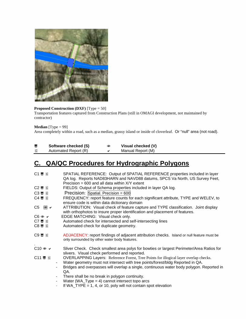
Proposed Construction (DXF) [Type = 50] Transportation features captured from Construction Plans (still in OMAGI development, not maintained by contractor) Median [Type = 99] Area completely within a road, such as a median, grassy island or inside of cloverleaf. Or “null” area (not road). Software checked (S) Visual checked (V) Automated Report (R) Manual Report (M) C. QA/QC Procedures for Hydrographic Polygons C1 SPATIAL REFERENCE: Output of SPATIAL REFERENCE properties included in layer
QA log. Reports NAD83HARN and NAVD88 datums, SPCS Va North, US Survey Feet, Precision = 600 and all data within X/Y extent
C2 FIELDS: Output of Schema properties included in layer QA log. C3 Precision: Spatial. Precision = 600 C4 FREQUENCY: report feature counts for each significant attribute, TYPE and WELEV, to
ensure code is within data dictionary domain C5 ATTRIBUTION: Visual check of feature capture and TYPE classification. Joint display
with orthophotos to insure proper identification and placement of features. C6 EDGE MATCHING: Visual check only. C7 Automated check for intersected and self-intersecting lines C8 Automated check for duplicate geometry. C9 ADJACENCY: report findings of adjacent attribution checks. Island or null feature must be only surrounded by other water body features. . C10 Sliver Check. Check smallest area polys for bowties or largest Perimeter/Area Ratios for
slivers. Visual check performed and reported. C11 OVERLAPPING Layers: Reference Forest, Tree Points for illogical layer overlap checks.
- Water geometry must not intersect with tree points/forest/bldg Reported in QA. - Bridges and overpasses will overlap a single, continuous water body polygon. Reported in
QA. - There shall be no break in polygon continuity. - Water (WA_Type = 4) cannot intersect topo arcs - If WA_TYPE = 1, 4, or 10, poly will not contain spot elevation

C12 Logical checks:
Does Water Level annotation agree with shoreline topo elevation? Can this be automated? WELEV value and annotation are within 4’ of nearest bankside topo contour TELEV WA_TYPE = 7 will not contain Anno or have WELEV value, but will likely contain a Spot
Elevation point If WA_TYPE = 1, poly can only contain DR_TYPE = 1 or 7 If WA_TYPE = 4, poly can only contain DR_TYPE = 4 If WA_TYPE = 7, poly may only contain DR_TYPE = 7 If WA_TYPE = 10, poly can only contain DR_TYPE = 10 If WA_TYPE = 99, poly can only contain DR_TYPE = 2, 3, 5, 6, 8, or 9 If WA_TYPE = 11, poly can only contain DR_TYPE = 2 No braided drain arcs Centerline through pond or lake, null connectors, centerline through Potomac River must exist inside corresponding water body polygons. All water body types (exceptions Type = 7 or 99) will contain a corresponding DR_TYPE
drain arc C13 Elevation: All Water polys (WA_TYPE = 4 only) > 1/10th acre contain WELEV value.
WELEV values contain only one decimal place in table and as labeled in ArcMap. Data Dictionary Elements for Water Bodies: Feature Class Name: WATER Type: PGDB Polygon Feature Class Description: This ArcGIS Feature Class contains water bodies, which are defined as any water feature such as double-line streams, ponds, lakes and reservoirs. Columns Name Type Size OBJECTID Long Integer 4 SHAPE OLE Object - WA_WELEV Single 4 WA_SOURCE Integer 2 WA_UPD_DATE Date/Time 8 WA_UPD_USER Integer 2 WA_TYPE Integer 2 SHAPE_Length Double 8 SHAPE_Area Double 8
WA_TYPE: 1 Double line stream 4 Lake or Pond 7 Dry Stormwater Retention Pond 10 Potomac River 11 Swamp/Marsh 99 Island or “null” (not water) Feature Depiction Descriptions based on USACE publication, EM 1110-1-1000, July 31, 2002 and further developed according to Loudoun County Data Dictionary. Nominal Scale: 200 Feet per Inch

Double line Stream [Type = 1] Digitize shorelines of streams, creeks or rivers wider than 15 ft, may or may not be navigable. Do not pull tree mass lines across double-wide creeks. Include area hidden under bridges, do not “break” polygon. Lake or Pond [Type = 4] A large inland body of usually fresh water. Show man-made reservoirs as lakes. Digitize shoreline. Join lake outline cleanly with river or creek line. Ponds are bodies of standing water much smaller than a lake, often man-made. Join pond outline cleanly with stream. Digitize shoreline of all water bodies with minimum of 50’ x 50’ or .05 acre. Populate WA_WELEV field with water elevation for all lakes and ponds greater than 1/10th of an acre. No spot elevation will be placed in these water bodies nor on the bank inside the neighboring enclosed contour. Include area hidden under bridges, do not “break” polygon. Dry Retention Pond [Type = 7] Manmade stormwater retention pond typically associated with flood control structure and/or berm. Typically dry, but may contain marsh vegetation, takes precedence over marsh/swamp. Digitize at top of berm. Capture associated culverts, riprap or dams in miscellaneous arcs or poly features. This feature will not be attributed with a WA_WELEV value, but rather shall usually contain a spot elevation at the lowest point inside the smallest enclosed contour. Spot may not be present if Dry Retention Ponds are too shallow-sloped. Dry ponds will be more prominent in eastern portion of County relative to stormwater drains and water impoundments. Potomac River [Type = 10] Digitize shorelines & islands Swamp or Marsh [Type = 11] Area of spongy, wet ground, usually harboring vegetation. Digitize any river, lake, pond, or creek outline within the swamp. Digitize outline of swamp and place or cells in the swamp area. No distinction is made between a swamp, marsh, or inundated area. Show all vegetation within the swamp area. Island [Type = 99] Land area surrounded by water body. Or “null” area (not water). Water Elevation Elevation of surface of water in feet, 1 decimal place. Do not show water elevations on Potomac River, single-line creeks, marshes or ditches. All lakes or ponds greater than 1/10th of an acre must have elevation calculated. Software checked (S) Visual checked (V) Automated Report (R) Manual Report (M) D. QA/QC Procedures for Drainage/Hydrographic arcs D1 SPATIAL REFERENCE: Output of SPATIAL REFERENCE properties included in layer QA
log. Reports NAD83HARN datum, SPCS Va North, US Survey Feet, Precision = 600 and all data within X/Y extent
D2 FIELDS: Output of Schema properties included in layer QA log. D3 Precision: Spatial. Precision = 600 D4 FREQUENCY: report feature counts for each significant attribute, TYPE, to ensure code is
within data dictionary domain D5 ATTRIBUTION: Visual check of feature capture and TYPE classification. Joint display with
orthophotos to insure proper identification and placement of features.

Hidden or “null” features are under bridges and overpasses, culverts, or across paved channels. Arcs meet width criteria
D6 EDGE MATCHING: Visual check only. D7 Automated check for intersected and self-intersecting lines, no zero length lines. D8 Automated check for duplicate geometry. D9 ADJACENCY: N/A. D10 Sliver Check. N/A D11 OVERLAPPING Layers:
Drain geometry must not intersect with /bldgs/ Do Drain arcs follow Topo Contour uphill “V’s”?
• Lake or pond, double line stream, and Potomac River features must contain only null centerline features that do not split or “braid” around island features. Arcs can flow into higher order stream arcs but cannot diverge and reconnect. Pick widest passage around island for single continuing centerline.
• All point features must not exist inside water bodies (exception Spot Elev inside WA_TYPE = 7 or 99) • If change in one layer affects another layer “by rule,” like roads covering drainage, then the affected layer must be split and
attributed appropriately
D12 Logical checks If DR_TYPE = 1, must be contained by poly WA_TYPE = 1 If DR_TYPE = 10, must be contained by poly WA_TYPE = 10 If DR_TYPE = 7, must be contained by poly WA_TYPE = 1 or 7 If DR_TYPE = 4, must be contained by poly WA_TYPE = 4 or 7 If DR_TYPE = 2, 3, 5, 6, 8, or 9, must be contained by poly WA_TYPE = 99 If DR_TYPE = 5, arc intersects Misc Arc, MI_TYPE = 5 If DR_TYPE = 6, arc intersects Misc Arc, MI_TYPE = 6 If DR_TYPE = 7, arc must connect w/ DR_Type = 1, 2 or 5 If DR_TYPE = 5, arc can be contained by poly RD_Type = 9
D15 Directionality: Automatic check for flow directionality, run entire drains data set through
directionality QA.mxd D16 Connectivity: Automatic check for connectivity. Automated check for overshoot-undershoot D17 Stormwater Integration Rules
Goal: Creation of an enhanced drainage arcs layer through integration of field-surveyed data, while maintaining connectivity, directionality and attribution of photogrammetrically-derived drains.
• Production/QA team should be concerned primarily with 3 point types, FEATURE = CULVTPT, PIPEIO, and CNTRLDE used as snapping points in drainage collection. In general there is no need to be concerned with other point types such as FEATURE=INLET or MANHOLE, however, team may find this useful in capture of other items in Misc Points and Misc Polygons. Sub-grade connections and direction can be determined using stormwater lines.
• Stormwater data provides guidance for directionality and rule of placement for location of culverts, pipes and headwalls. Snap to coincident features within 20’ radius of proximity. If no stormwater GPS point exists within 20’ radius of proximity, compilers should represent headwall as best as possible along drain network.
• Stormwater data will take precedence over cartographically represented headwalls and will also represent
transitions from surface to sub-grade drainage. • Compilers should perform a 2-D snap to stormwater points and endpoints then pull 3-D from photogrammetry.
• Distinct compilation/integration method and combined accuracy shall be detailed in metadata.

• Latest (as of 3/2/05) Rules concerning application of Stormwater Infrastructure GIS files during drainage
compilation:
o Snap visible surface drain arcs to CULVTPT and/or PIPEIO endpoints along network within 20’ radius of proximity. CULVTPT takes precedence over PIPEIO when both appear within 20’ radius of proximity.
o Collect sub-grade, null drains through culverts (DR_Type = 5) per usual, regardless of existence of CULVERT or PIPE line. Do not “mix and match” by substituting stormwater lines.
o If open channel (DR_Type = 9) is defined and visible along roadside ditch, snap to CULVTPT culvert points and connect with null drains (DR_Type = 5).
o Use stormwater lines to assist in determination of surface drainage flow direction. There is a high degree of confidence in accuracy of flow direction as these were collected in the field by surveyors.
o Pond Null arcs (DR_Type = 4) must snap to control devices CNTRLDE if present in wet or dry ponds.
o All above-grade, Miscellaneous features (manholes, headwalls/culverts, paved channels) will be captured as usual, per contract. Headwalls (MI_Type = 5) shall be coincident with CULVTPT points, which connect surface drain arcs (DR_Type = 2, 6, or 9) and sub-grade null arcs (DR_Type = 5)
• Contractor will convert final drain DGN to 3D shapefile as additional deliverable
Data Dictionary Elements for Drainage: Feature Class Name: DRAINS Type: PGDB Line Feature Class Description: This ArcGIS Feature Class contains drains, which are defined as any visible surface drainage feature. Drainage arcs must logically follow topo contours and are not disconnected when traveling through culverts, under bridges or representing the centerline of double-line streams and ponds. Drain arcs will be captured according to proper orientation or direction of flow. Columns Name Type Size OBJECTID Long Integer 4 SHAPE OLE Object - DR_CLASS Text 2 DR_SOURCE Integer 2 DR_UPD_DATE Date/Time 8 DR_UPD_USER Integer 2 DR_TYPE Integer 2 SHAPE_Length Double 8

DR_CLASS: Former TYPE item, renamed CLASS prior to 2003 data dictionary changes. Not maintained by Contract. A Alluvial F Unknown I Intermittent N Type not evaluated P Perennial DR_TYPE: Type classification 1 Null CL through Double line stream 2 Single-Line stream network 3 Soil drain 4 Null CL through pond or lake 5 Null CL through bridge or culvert 6 Null CL over paved channel
7 Null Connecting Arcs 8 Discontinuous drain 9 CL of open (unpaved) channel or ditch 10 Null CL through Potomac River
Feature Depiction Descriptions based on USACE publication, EM 1110-1-1000, July 31, 2002 and further developed according to Loudoun County Data Dictionary. Nominal Scale: 200 Feet per Inch Drainage - which are defined as any visible surface drainage feature. Drainage arcs must logically follow topo contours and are not disconnected when traveling through culverts, under bridges or representing the centerline of double-line streams and ponds. Drain arcs will be captured according to proper orientation or direction of flow and will connect where possible to Storm Water Drainage network. Centerline through double line stream [Type = 1] Null centerline of a double-line stream polygon in Water Bodies. Captured/Coded by contractor. Single-line Creek /Stream [Type = 2] Nonnavigable stream. Digitize center lines of streams narrower than 15 ft. Streams wider than 15’ are captured as double-line stream polygons in Water Bodies. Join creeks cleanly with rivers, lakes, or ponds. Captured/Coded by contractor . #Soil Drain [Type = 3] Captured/Coded by County. Centerline through pond or lake [Type = 4] Non-tangible or null arc that is created in the central location of standing water to show continuity amongst incoming and outgoing streams. Captured/Coded by contractor . Centerline through bridge or Culvert [Type = 5] Connect with straight line (null arc) from the last visible point upstream to first visible point of egress. Nodes shall be placed at headwalls or culverts where visible, not clipped to road casing boundary. In all cases where a surface drainage features goes underground, contractor shall use this code regardless of culvert or headwall presence. Captured/Coded by contractor . Centerline across Paved Ditch [Type = 6] Digitize null centerline of paved ditch. Do not show water edges inside ditch. Retaining wall has precedence over paved ditch. Cap ends or join cleanly with headwalls, if present. Paved channels will be more prominent in eastern portion of County relative to stormwater drains and water impoundments. Captured/Coded by contractor Null Connectors [Type = 7]

Null arcs designed to maintain connectivity and directionality of flow by connecting single line streams to double line stream centerlines or one double line stream centerline to another. Captured/Coded by contractor # Discontinuous Drain [Type = 8] Drain that is not a continuous above ground feature. Captured/Coded by County. Centerline of open (unpaved) channels or ditches [Type = 9] Unpaved, manmade drainage features normally adjacent to roadways. Digitize centerline of any trough greater than 200 feet in length. Captured/Coded by contractor Centerline through Potomac River [Type = 10] Null CL through Potomac River. Captured/Coded by contractor Software checked (S) Visual checked (V) Automated Report (R) Manual Report (M) E. QA/QC Procedures for Forestry Polygons E1 SPATIAL REFERENCE: Output of SPATIAL REFERENCE properties included in layer
QA log. Reports NAD83HARN datum, SPCS Va North, US Survey Feet, Precision = 600 and all data within X/Y extent
E2 FIELDS: Output of Schema properties included in layer QA log. E3 Precision: Spatial. Precision = 600 E4 FREQUENCY: report feature counts for each significant attribute, TYPE, to ensure code is
within data dictionary domain E5 ATTRIBUTION: Visual check of feature capture and TYPE classification. Joint display
with orthophotos to insure proper identification and placement of features. E6 EDGE MATCHING: Visual check only. E7 Automated check for intersected and self-intersecting lines E8 Automated check for duplicate geometry. E9 ADJACENCY: report findings of adjacent attribution checks. Clearing or “Not Forest” must be
only surrounded by other forest features E10 Sliver Check. Check smallest area polys for bowties or largest Perimeter/Area Ratios for
slivers. Visual check performed and reported. E11 OVERLAPPING Layers: Forest cannot overlap buildings E12 Logical checks: E.12 Forest polygon must not intersect with tree points, water
polygons, misc polygons E.12 Forest polygon must not intersect with misc arcs except for misc types 5, 8, or 11
Data Dictionary Elements for Forest: Feature Class Name: FOREST Type: PGDB Polygon Feature Class Description: This ArcGIS Feature Class contains forest tracts, which are defined as any tree cover or dense vegetation.
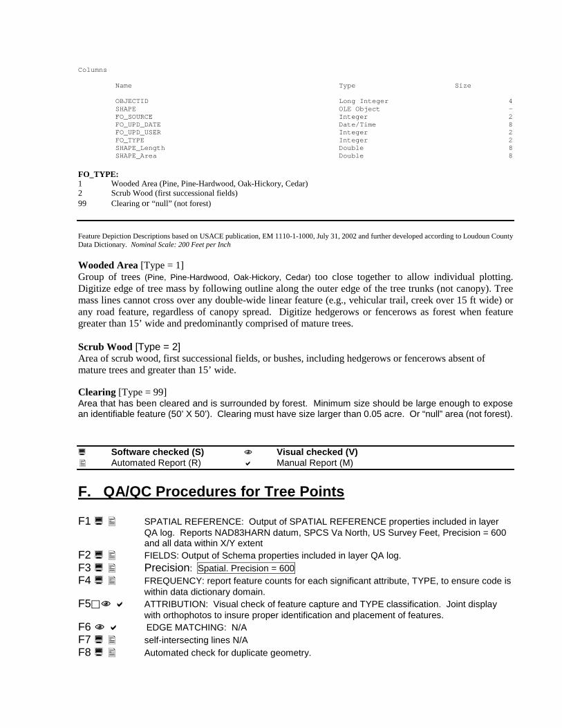
Columns Name Type Size OBJECTID Long Integer 4 SHAPE OLE Object - FO_SOURCE Integer 2 FO_UPD_DATE Date/Time 8 FO_UPD_USER Integer 2 FO_TYPE Integer 2 SHAPE_Length Double 8 SHAPE_Area Double 8 FO_TYPE: 1 Wooded Area (Pine, Pine-Hardwood, Oak-Hickory, Cedar) 2 Scrub Wood (first successional fields) 99 Clearing or “null” (not forest) Feature Depiction Descriptions based on USACE publication, EM 1110-1-1000, July 31, 2002 and further developed according to Loudoun County Data Dictionary. Nominal Scale: 200 Feet per Inch Wooded Area [Type = 1] Group of trees (Pine, Pine-Hardwood, Oak-Hickory, Cedar) too close together to allow individual plotting. Digitize edge of tree mass by following outline along the outer edge of the tree trunks (not canopy). Tree mass lines cannot cross over any double-wide linear feature (e.g., vehicular trail, creek over 15 ft wide) or any road feature, regardless of canopy spread. Digitize hedgerows or fencerows as forest when feature greater than 15’ wide and predominantly comprised of mature trees. Scrub Wood [Type = 2] Area of scrub wood, first successional fields, or bushes, including hedgerows or fencerows absent of mature trees and greater than 15’ wide. Clearing [Type = 99] Area that has been cleared and is surrounded by forest. Minimum size should be large enough to expose an identifiable feature (50’ X 50’). Clearing must have size larger than 0.05 acre. Or “null” area (not forest). Software checked (S) Visual checked (V) Automated Report (R) Manual Report (M) F. QA/QC Procedures for Tree Points F1 SPATIAL REFERENCE: Output of SPATIAL REFERENCE properties included in layer
QA log. Reports NAD83HARN datum, SPCS Va North, US Survey Feet, Precision = 600 and all data within X/Y extent
F2 FIELDS: Output of Schema properties included in layer QA log. F3 Precision: Spatial. Precision = 600 F4 FREQUENCY: report feature counts for each significant attribute, TYPE, to ensure code is
within data dictionary domain. F5 ATTRIBUTION: Visual check of feature capture and TYPE classification. Joint display
with orthophotos to insure proper identification and placement of features. F6 EDGE MATCHING: N/A F7 self-intersecting lines N/A F8 Automated check for duplicate geometry.

F11 Sliver Check. N/A F12 OVERLAPPING Layers: All singletree features must not exist inside buildings, wooded area, scrub wood, road, driveway, runway, stream, river, pond, bridge, pool, or impervious recreational athletic courts. Data Dictionary Elements for Tree points: Feature Class Name: TREES Type: PGDB Point Feature Class Description: This ArcGIS Feature Class contains individual trees outside of forested areas. Columns Name Type Size OBJECTID Long Integer 4 SHAPE OLE Object - TR_SOURCE Integer 2 TR_UPD_DATE Date/Time 8 TR_UPD_USER Integer 2 TR_TYPE Integer 2 TR_TYPE: 1 Any Single Tree Feature Depiction Descriptions based on USACE publication, EM 1110-1-1000, July 31, 2002 and further developed according to Loudoun County Data Dictionary. Nominal Scale: 200 Feet per Inch
Tree Any isolated, visible, single standing tree or row of trees, less than 15’ wide, where individual trees are separated by an average distance of greater than 10’ apart. Digitize center of trunk where trees are not too close for individual plotting.
o Return to collection criteria or method that produced the original Ph 1 Pilot tree layer with fewer features in an effort to reduce instances where we are collecting small trees (<6’ tall), shrubs and other small garden or home landscape features within 6’ of building footprints.

Software checked (S) Visual checked (V) Automated Report (R) Manual Report (M) G. QA/QC Procedures for Miscellaneous Cultural Polygons G1 SPATIAL REFERENCE: Output of SPATIAL REFERENCE properties included in layer
QA log. Reports NAD83HARN datum, SPCS Va North, US Survey Feet, Precision = 600 and all data within X/Y extent
G2 FIELDS: Output of Schema properties included in layer QA log. G3 Precision: Spatial. Precision = 600 G4 FREQUENCY: report feature counts for each significant attribute, TYPE, to ensure code is
within data dictionary domain G5 ATTRIBUTION: Visual check of feature capture and TYPE classification. Joint display
with orthophotos to insure proper identification and placement of features. G6 EDGE MATCHING: Visual check only. G7 Automated check for intersected and self-intersecting lines G8 Automated check for duplicate geometry. G9 ADJACENCY: report findings of adjacent attribution checks. G10 Sliver Check. Check smallest area polys for bowties or largest Perimeter/Area Ratios for
slivers. Visual check performed and reported. G11 OVERLAPPING Layers: Misc Poly cannot overlap buildings
Data Dictionary Elements for Miscellaneous Polys: Feature Class Name: MISCPoly Type: PGDB Polygon Feature Class Description: This ArcGIS Feature Class contains miscellaneous POLYGONS, which are any other areal planimetric features that do not exist in any other layer. Columns Name Type Size OBJECTID Long Integer 4 SHAPE OLE Object - MI_SOURCE Integer 2 MI_UPD_DATE Date/Time 8 MI_UPD_USER Integer 2 MI_TYPE Integer 2 SHAPE_Length Double 8 SHAPE_Area Double 8 MI_TYPE:
1 Pools 2 Impervious Recreational Courts 3 Non-Impervious Recreational Fields 4 Cemetery 6 Rip Rap
7 Quarry 8 Area under Construction/Storage/Debris 9 Golf Course Feature (Traps, Tees & Greens) 99 “null” (not miscellaneous poly) space
Feature Depiction Descriptions based on USACE publication, EM 1110-1-1000, July 31, 2002 and further developed according to Loudoun County Data Dictionary. Nominal Scale: 200 Feet per Inch Pool [Type = 1] Digitize exterior edge of concrete around in ground or above ground pools. Also use pool for aeration pools in industrial areas. Does not include kiddie pools, hot tubs, garden fish ponds, trampolines or any other feature typically smaller than 15’ in diameter or less than 175 sq. ft. in total area.

"do not capture circular features, approximately 10' in diameter, with black color, not surrounded by fences, that resemble trampolines. Do not confuse with above ground pools that are much larger and typically have decks and or fences attached." Swimming pools have walls, trampolines do not.
These images below show trampolines…
Impervious Recreational Athletic Courts [Type = 2] Outline paved surface area for recreation, such as Tracks, Tennis or Basketball Court. Outline inside of fenced area if applicable. Non-Impervious Athletic Field [Type = 3] Football, baseball, softball, soccer, tot lots, horse tracks, paint ball fields, etc. Outline field. Do not label. Do not capture horse exercise pens. Show paved or unpaved tracks as paved or unpaved drives. Cemetery [Type = 4] Delineate cemetery boundary only if not bounded by a fence line. Show paved and unpaved drives and buildings. Do not show headstones. Capture sidewalks if present Riprap (Over 20 ft x 20 ft) [Type = 6]

Rocks placed along slopes to lessen erosion. Outline large riprap. Contour general slope of riprap with indefinite contours to represent nonpermanent irregular surface. Rip rap will be more prominent in eastern portion of County relative to stormwater drains and water impoundments. Quarry [Type = 7] Mining area. No distinction is made between rock (consolidated) material mines and loose (unconsolidated) material mines. Show natural features present within quarry. Digitize quarry outline. Place spot elevations at lowest points of active quarries. Area Under Construction, Storage or Debris [Type = 8] Digitize outline of entire area under construction. Show any roads under construction as unpaved roads. Digitize buildings under construction and any feature that has been completed (e.g., completed building). Do not show debris or storage within the area outline. Contour with indefinite TO_TYPEs- Do not use this classification for individual home site unless topo grade is visibly unfinished. This code is used more often for larger scale subdivision or commercial sites. The purpose of the area under construction is to point out that contours are "unsettled" or subject to further grading so they are indefinite within the boundaries of the construction area. Just because dirt is visible, doesn't necessarily mean that the contouring is indefinite. Many lots are finished grading if foundations, houses, driveways, sidewalks and roads are present and the yards are simply waiting for sod. Storage = Stacked material or piles of dirt, sand, gravel, salt, etc. Digitize outline of area. Do not contour piled areas or areas stacked so that the ground is not visible. Retaining wall symbology takes precedence over storage outline. Outline junkyards with storage line. Debris (Greater than 20 ft x 20 ft) = Scattered and unsorted material completely obscuring ground. Digitize outline of area. Do not contour. Golf Course feature [Type = 9] Fairways, Tees, greens, and sand traps/bunkers. Do not show outline of golf course (misc. arc feature). Show all paved drives (cart paths) that are permanent in nature in misc. arcs as “trails”. Show all hydrology and natural features. Null Feature [Type = 99] “Null” area (not miscellaneous) that comprises all of the non-classified misc. poly land area.

Software checked (S) Visual checked (V) Automated Report (R) Manual Report (M) H. QA/QC Procedures for Miscellaneous Cultural Arcs H1 SPATIAL REFERENCE: Output of SPATIAL REFERENCE properties included in layer
QA log. Reports NAD83HARN datum, SPCS Va North, US Survey Feet, Precision = 600 and all data within X/Y extent
H2 FIELDS: Output of Schema properties included in layer QA log. H3 Precision: Spatial. Precision = 600 H4 FREQUENCY: report feature counts for each significant attribute, TYPE, to ensure code is
within data dictionary domain (Report to include new code 18 for sound barriers) H5 ATTRIBUTION: Visual check of feature capture and TYPE classification. Joint display
with orthophotos to insure proper identification and placement of features. H6 EDGE MATCHING: Visual check only. H7 Automated check for intersected and self-intersecting lines, no zero length lines. H8 Automated check for duplicate geometry. H9 ADJACENCY: N/A. H10 Sliver Check. N/A H11 OVERLAPPING Layers: Reference Forest, Tree Points for illogical layer overlap checks.
Pads & Patios must touch buildings when adjacent. Decks must touch buildings when adjacent.
• All headwall or culvert must bisect or intersect a drain arc feature
H12 Logical checks: If MI_TYPE = 5, arc intersects DR_TYPE = 5 If MI_TYPE = 6, arc intersects DR_TYPE = 6 MI_TYPE = 12 or 13 (pads, decks, patios) must touch BL_TYPE = 1 when adjacent
Data Dictionary Elements for Miscellaneous Arcs: Feature Class Name: MISCARC Type: PGDB Line Feature Class Description: This ArcGIS Feature Class contains miscellaneous arcs, which are any other linear planimetric features that do not exist in any other layer. Layer includes former utility arcs layer. Columns Name Type Size OBJECTID Long Integer 4 SHAPE OLE Object - MI_SOURCE Integer 2 MI_UPD_DATE Date/Time 8 MI_UPD_USER Integer 2 MI_TYPE Integer 2 SHAPE_Length Double 8
MI_TYPE:
1 Sidewalks 2 Road Shoulders 3 Guard rails 4 Dams/Levees 5 Headwall/Culvert
6 concrete channels /paved ditches 7 docks, boat ramps 8 trails (paved, unpaved, or gravel
hiking/biking/pedestrian) 9 golf course boundary

10 retaining wall 11 fence 12 pads/patios 13 decks 14 Utilities
15 Transformer substation 16 Tank 17 Footbridge 18 Sound Barrier/High Wall
Feature Depiction Descriptions based on USACE publication, EM 1110-1-1000, July 31, 2002 and further developed according to Loudoun County Data Dictionary. Nominal Scale: 200 Feet per Inch
Sidewalks [Type = 1] Concrete pedestrian walkways directly adjacent or parallel to roads or network through neighborhoods. Sidewalks are different from asphalt-paved fitness paths (see “Trails”) that are typically separated from the roads by landscaping or grassy patches and are non-linear in appearance. Impervious road polygons adjacent to sidewalks take precedence over sidewalks. Not included are private walkways leading from residence to driveway or to sidewalk adjacent to road, however, walkways of this same nature (from building to sidewalk or parking lots) in cemeteries and commercial or industrial complexes are to be captured as sidewalks. Road Shoulder [Type = 2] Typically graveled buffer area between edge of paved road and edge of shoulder. Place Road Shoulder arc at interface with adjacent land feature only, not at edge of pavement. Minimum width of 10 feet. Guardrail has precedence over shoulder. Guardrail Over 100 ft Long [Type = 3] Digitize center line of any visible guardrails. Dam / Levee [Type = 4] Barrier across river, creek, or swamp to regulate or obstruct water flow. Earth wall for fluid retention, usually found along rivers or canals. Digitize outer edge of levee on planimetric maps only (contours define levees on topographic maps). Headwall or Culvert [Type = 5] Wall at entrance of culvert to convey surface water below grade. Digitize center line. See Stormwater integration rules, D17, for more information on placement and representation of Headwalls and Culverts. Paved Concrete ditch or channel [Type = 6] Digitize outline of channels wider than 15’ that conveys surface water above grade. (See also null Drainage feature for paved ditches.) Paved channels will be more prominent in eastern portion of County relative to stormwater drains and water impoundments. Docks, boat ramps or Commercial Pier [Type = 7] Deck supported by posts extended over water. Digitize edge of pier. Do not show private piers. Trail [Type = 8] Visible, permanent dirt, gravel or paved passageway greater than 200 ft long primarily used for pedestrian or bicycle traffic. Digitize center line of trail. Different than concrete sidewalks adjacent to roads (see “Sidewalks”). Includes paved cart paths on golf courses that are permanent in nature, gravel or asphalt-paved fitness paths that are typically separated from the roads by landscaping or grassy patches and are non-linear in appearance. Also includes visible dirt trails through woods that may convey foot, bike, equestrian or 4X4 vehicle traffic. Does not include W&OD Railroad Regional Park Trail (see Transportation). Do not include “farm trails” created by farm equipment or private paths from field to field. Golf Course [Type = 9] Show outline of golf course only if not bounded by a fence. Retaining Wall (Major) [Type = 10]
Fixed structure retaining earth located along thoroughfares. Digitize center line of wall. Major retaining wall has precedence over fence, edge of pavement, and minor retaining wall. Snap contours to retaining walls. Ornamental walls = Fixed structure of concrete or brick not used for retention of earth. Digitize center line of walls over 20 ft long. Ornamental wall has precedence over fence. Fence [Type = 11] Digitize centerlines of visible property line and cross-country fences. No distinction between wire or wood. Do not include temporary fences like silt, snow or drainfield delineation fences. (larger than 20’ X 20’ or greater than 50’ in length) Pads & Patios [Type = 12] Impervious surfaces associated with residential homes. Arcs joined cleanly to building polygons when adjacent Decks [Type = 13] Wooden Additions to buildings, arcs joined cleanly to building polygons. Digitize outline of area. Utility [Type = 14] Cross-country aboveground pipeline used for transportation of liquid, gas, or matter usually found near industrial areas or public utilities plants. Digitize center line. Do not show supporting structures. Substation or Transformer greater than 20 ft x 20 ft [Type = 15] High-voltage units grouped together, usually within a fence. Digitize outline if not enclosed by fence. Show large structures within substations as miscellaneous structures. Substation outline has precedence over slab, unpaved drive, and trail. Do not show individual poles, pipes, or transformers within substation boundary. Tank (Visible) [Type = 16] Public utility storage tank. Digitize edge of tank.( do not include LP tanks at private homes) Footbridge [Type = 17] Smaller bridge, typically conveying a trail over a creek or depression. Does not convey cars. Digitize centerline of structure, if trail is present, connect footbridge to trail node to node. SoundBarrrier [Type = 18] A free standing high wall (approx 8ft or more in height) made of wood or concrete parallel to the roadway for absorbing sound. Length specifications- minimum of 200 ft’ (does not include temporary Jersey walls) Note: OMAGI is in the process of adding features- ‘Crosswalk’ and ‘Shared use path’ in the Misarc layer. It may add new feature types in misarc layer. Software checked (S) Visual checked (V) Automated Report (R) Manual Report (M) I. QA/QC Procedures for Miscellaneous Cultural Points I1 SPATIAL REFERENCE: Output of SPATIAL REFERENCE properties included in layer
QA log. Reports NAD83HARN datum, SPCS Va North, US Survey Feet, Precision = 600 and all data within X/Y extent
I2 FIELDS: Output of Schema properties included in layer QA log. I3 Precision: Spatial. Precision = 600 I4 FREQUENCY: report feature counts for each significant attribute, TYPE, to ensure code is
within data dictionary domain. I5 ATTRIBUTION: Visual check of feature capture and TYPE classification. Joint display
with orthophotos to insure proper identification and placement of features.

I6 EDGE MATCHING: N/A I7 self-intersecting lines N/A I8 Automated check for duplicate geometry. I9 ADJACENCY: N/A. I10 Sliver Check. N/A I11 OVERLAPPING Layers: Misc Pt cannot lie within buildings, water bodies or forests I12 Logical checks: Data Dictionary Elements for Miscellaneous points: Feature Class Name: MISCPT Type: PGDB Point Feature Class Description: This ArcGIS Feature Class contains miscellaneous points, which are any other point planimetric features that do not exist in any other layer. Layer is combined with former utility points. Columns Name Type Size OBJECTID Long Integer 4 SHAPE OLE Object - MI_SOURCE Integer 2 MI_UPD_DATE Date/Time 8 MI_UPD_USER Integer 2 MI_TYPE Integer 2 MI_TYPE:
1 poles 2 Manholes 3 Undetermined, miscellaneous points 4 Utility pylon (large & small) 5 Broadcast Antenna/Transmission Tower
Feature Depiction Descriptions based on USACE publication, EM 1110-1-1000, July 31, 2002 and further developed according to Loudoun County Data Dictionary. Nominal Scale: 200 Feet per Inch Pole [Type = 1] Utility pole from which power, telephone, street lights or cable television lines are suspended. Digitize center of pole. Manhole [Type = 2] A hole through which one can enter a sewer, conduit, etc. Manholes may be located on paved or unpaved surfaces. Digitize center of manhole. Undetermined or Miscellaneous Point [Type = 3] Any point that is not distinctly identifiable as a pole, manhole, utility pylon or transmission tower. Could be a hydrant, cable/phone box, etc. Digitize center of element.
Utility Pylon (large & small), [Type = 4] Large structure for supporting power lines across long distances. Digitize center of structure. Broadcast Antenna / Transmission Tower [Type = 5] Radio, television, cell or other wireless communication tower. Digitize center of tower.

Software checked (S) Visual checked (V) Automated Report (R) Manual Report (M) J. QA/QC Procedures for Topographic Contours: J1 SPATIAL REFERENCE: Output of SPATIAL REFERENCE properties included in layer
QA log. Reports NAD83HARN and NAVD88 if applicable datums, SPCS Va North, US Survey Feet, Precision = 600 and all data within X/Y extent
J2 FIELDS: Output of Schema properties included in layer QA log. J3 Precision: Spatial. Precision = 600 J4 FREQUENCY: report feature counts for each significant attribute, TYPE and TELEV, to
ensure codes are within data dictionary domain. An exclusion rule will be added for MiscPoly Type = 7 (Quarry) as Topo elevations may be lower than dictionary domain.
J5 ATTRIBUTION: Visual check of feature capture and TYPE classification. Joint display with orthophotos to insure proper identification and placement of features. Automated check to insure proper elevation and values evenly divisible by 4. Length: There is no length limit or threshold applied to smallest contours, enclosed
or otherwise. J6 EDGE MATCHING: Visual check only.
o To eliminate compiler judgment calls, remap completely and only within selected stereo models. Apply buffer around stereo model with intent to edge match all layers with neighboring legacy data inside that buffer. Topography will then be consistent with overlaying roads and other features because of updated DTM.
o Topography contours will split by default at or near stereo model boundary because new DTM dictates regeneration. All judgment and interpretation of “significant change” is removed from the compiler.
J7 Automated check for intersected and self-intersecting lines, no zero length lines. J8 Automated check for duplicate geometry. J9 ADJACENCY: N/A. J10 Sliver Check. N/A J11 OVERLAPPING Layers: Report closed topo contours without spot elevations with the
pond exception. If change in one layer affects another layer “by rule,” like bridges over topo, then the affected layer must be split and attributed appropriately.
J12 Logical checks: Obscure topo contours TO_TYPE = 3, 4 are clipped and contained by dense ground
cover/ buildings and under bridges. Contour coding inside forest will be based on visual inspection. Obscure contours should only be in forested areas that are visibly dense. Forests polygons that are not dense should have regular contours. Obscured areas represent areas where the ground is not clearly visible in the stereo images. Some areas covered by the forest polygon may not be in the obscured area polygon. If the compiler can see the ground through the trees, they will place mass points and/or break lines.
Automated check to insure that only null contours appear within building outlines or beneath bridge decks. BL_TYPE = 1, 2 or RD_TYPE = 9 must clip and contain “null” contour.
Logical check between TELEV values and neighboring Spot Elevations SELEVs J13 Elevation: TELEV values are evenly divisible by 4 and have zero decimal places J14 Placement: Aesthetics, contour smoothing should be visually QA/QC’d. A balance
should exist between appearance and accuracy when smoothed. J15 Directionality: N/A J16 Connectivity: Automatic check for connectivity or disconnected segments. Automated
check for overshoot-undershoot. Dangles only permissible at boundary edges.

Data Dictionary Elements for Topography: Feature Class Name: TOPO Type: PGDB Line Feature Class Description: This ArcGIS Feature Class contains Topographical Contour Lines at a 4’ contour interval Columns Name Type Size OBJECTID Long Integer 4 SHAPE OLE Object - TO_TELEV Integer 2 TO_SOURCE Integer 2 TO_UPD_DATE Date/Time 8 TO_UPD_USER Integer 2 TO_TYPE Integer 2 SHAPE_Length Double 8 TO_TELEV: Elevation in feet, no decimals TO_TYPE: TO_TYPE 1- Index – every 5th contour TO_TYPE 2- Intermediate – all other contours at 4’ intervals TO_TYPE 3- Index Obscured – every 5th contour that falls in an obscured or null area (dense ground cover/ buildings and under bridges) TO_TYPE 4- Intermediate Obscured– all other contours that fall in an obscured or null area (dense ground cover/ buildings and under bridges)
Feature Depiction Descriptions based on USACE publication, EM 1110-1-1000, July 31, 2002 and further developed according to Loudoun County Data Dictionary. Nominal Scale: 200 Feet per Inch

Software checked (S) Visual checked (V) Automated Report (R) Manual Report (M) K. QA/QC Procedures for Elevation Points
K1 SPATIAL REFERENCE: Output of SPATIAL REFERENCE properties included in layer
QA log. Reports NAD83HARN and NAVD88 datums, SPCS Va North, US Survey Feet, Precision = 600 and all data within X/Y extent
K2 FIELDS: Output of Schema properties included in layer QA log. K3 Precision: Spatial. Precision = 600 K4 FREQUENCY: report feature counts for each significant attribute. SELEV, to ensure value
is within data dictionary domain (150’ < SELEV <1975’) An exclusion rule will be added for Spot elevations in Misc Poly type = 7 (Quarry) as spot elevations have to placed at lowest points of active quarries.
K5 ATTRIBUTION: K6 EDGE MATCHING: N/A K7 self-intersecting lines N/A K8 Automated check for duplicate geometry. K9 ADJACENCY: N/A. K10 Sliver Check. N/A K11 OVERLAPPING Layers: K12 Logical checks:
Spot Elev cannot lie within bldgs or Water, WA_TYPE = 1, 4, or 10 Check relationship w/ Topography. Possibly relate topo arcs to Spot Elevations to
ensure points fall within 4’ range of neighboring topo contours. SELEV value is within 4’ of nearest topo contour TELEV value. Spot Elevation points must lie within proper sequence of Topography contours according to elevation value.
K13 Elevation: SELEV values have one decimal place K14 Placement: Spot Elevations are placed in all appropriate locations: cul-de-sacs, closed
contours, saddles, intersections, and at intervals such that they are no more than 2’ apart when mapped at 1:2400 scale, etc. Visual check performed.
Data Dictionary Elements for Spot Elevation points: Feature Class Name: SPOTELEV Type: PGDB Point Feature Class Description: This ArcGIS Feature Class contains Spot elevation points Columns Name Type Size OBJECTID Long Integer 4 SHAPE OLE Object - SP_SELEV Single 4 SP_SOURCE Integer 2 SP_UPD_DATE Date/Time 8 SP_UPD_USER Integer 2

SP_SELEV: Elevation in feet. SELEV values contain only one decimal place in table and as labeled in ArcMap.
Feature Depiction Descriptions based on USACE publication, EM 1110-1-1000, July 31, 2002 and further developed according to Loudoun County Data Dictionary. Nominal Scale: 200 Feet per Inch Spot Elevation Supplemental elevation used in conjunction with contour information. Spot elevations should be placed at the following points: a. All road and/or railroad intersections, cul-de-sacs. b. At the center of bridges on center line of road. d. At the highest point of closed contour tops. e. At the lowest point of closed depressions, significant saddles, and quarries. f. At points visible through dense vegetation in obscured areas. g. At any location necessary to provide that no more than 2 in. exist between any contour and/ or spot elevation.

Software checked (S) Visual checked (V) Automated Report (R) Manual Report (M) L. QA/QC Procedures for Sidewalk Centerline (Optional) H1 SPATIAL REFERENCE: Output of SPATIAL REFERENCE properties included in layer
QA log. Reports NAD83HARN datum, SPCS Va North, US Survey Feet, Precision = 600 and all data within X/Y extent
H2 FIELDS: Output of Schema properties included in layer QA log. H3 Precision: Spatial. Precision = 600 H4 FREQUENCY: report feature counts for each significant attribute, TYPE, WIDTH, and
SURFACE. H5 ATTRIBUTION: Visual check of feature capture and TYPE classification. Joint display
with orthophotos to insure proper identification and placement of features. H6 EDGE MATCHING: Visual check only. H7 Automated check for intersected and self-intersecting lines, no zero length lines. H8 Automated check for duplicate geometry. H9 ADJACENCY: N/A. H10 Sliver Check. N/A H11 OVERLAPPING Layers: N/A
H12 Logical checks: N/A Data Dictionary Elements for Sidewalk: Feature Class Name: SIDEWALK Type: PGDB Line Feature Class Description: This ArcGIS Feature Class contains paved surfaces (concrete, brick or asphalt) that are parallel to and near street travel ways. This includes along both major and minor transportation features. The existing sidewalk layer only has features along major transportation. This will add all sidewalks within townhouse and condominium/apartment communities as well as parking lots and provide better connectivity through these areas. This will not include sidewalks that lead to the entrance of a house or building. The sidewalk centerline must be captured with the width of the sidewalk as an attribute. The sidewalks are intended to be a network feature. The sidewalk centerline will be captured beginning from edge at one end of the road, following along the course of the sidewalk to the next edge of pavement. If the sidewalk continues across the road or across a driveway then a segment (connector) will be created for connectivity purposes. These connector segments will be coded with CONNECTOR type value. Columns Name Type Size OBJECTID Long Integer 4 SHAPE OLE Object - SI_SOURCE Integer 2 SI_UPD_DATE Date/Time 8 SI_UPD_USER Integer 2 SI_TYPE Integer 2 SI_WIDTH Integer 4
SI_SURFACE Integer 2 SHAPE_Length Double 8

SI_TYPE:
1 SIDEWALK 2 CONNECTOR 3 CROSSWALK
Where it is obvious that a sidewalk connects to another sidewalk across a street, a connector must connect the features in order to support a network feature class. A connector is a segment connecting a sidewalk on one side of a street to a sidewalk on the other side or when a sidewalk crosses over a driveway or entrance to a parking lot. It provides the connectivity to the network where the physical sidewalk ends.
Sidewalks [Type = 1] Sidewalks are different from asphalt-paved fitness paths (see “Trails”) that are typically separated from the roads by landscaping or grassy patches and are non-linear in appearance. Connector [Type = 2] A connector is a segment connecting a sidewalk on one side of a street to a sidewalk on the other side or when a sidewalk crosses over a driveway or entrance to a parking lot. It provides the connectivity to the network where the physical sidewalk ends. Crosswalk [Type = 3] A marked part of a road where pedestrians have right of way to cross. SI_WIDTH:
2 less than 2 feet 4 2-4 feet 6 4-6 feet 8 6-8 feet 10 8 feet or greater
SI_SURFACE:
1 CONCRETE 2 ASPHALT 3 BRICK 4 OTHER

Unique Identifier Field: County has added unique identifier field to some of the base map layers so that the updates performed on a given year can be tracked. Currently there are no attribute values that allow feature to be consistently matched between updates. For this purpose the countywide source dataset has a unique identifier field. Contractor will deliver the updated data with that unique identifier. It’s not something that the contractor will populate, but contractor will keep it intact as it passes through their editing process. The following layers have a unique identifier field: Layer Unique Identifier Buildings BU_ LOUD_ID Rdcasing RD_ LOUD_ID Water WA_ LOUD_ID Drains DR_LOUD_ID Misarc MISA_ LOUD_ID Mispoint MISP_ LOUD_ID Mispoly MISPO_ LOUD_ID Forest FO_ LOUD_ID Trees TR_ LOUD_ID

Appendix B
Loudoun County Base Map Maintenance Cycle- 2007-2017
Base map update area map app is located at: http://loudoungis.maps.arcgis.com/apps/StoryMapBasic/index.html? appid=1538f6346bb74245b02ab336c89c775d
Refer to Loudoun’s Basemap story map to get more information on Loudoun’s Basemap and update years: http://arcg.is/1Gm9Sg2

Appendix C
Loudoun County is covered by 684 Ortho Tiles. Refer to Loudoun’s Basemap story map to
get recent information on Orthoimagery and Photocenters 2019. http://arcg.is/1Gm9Sg2

Appendix D
QA/QC Program output
Start Date/Time: 4/12/2019 02:11:32 PM
SECTION #Pilot: DATA REVIEWER CHECKS
PLEASE NOTE, DOMAIN FREQUENCY CHECKS ARE PROVIDED FOR THE TILE AREA, FOR ALL FEATURES WHICH INTERSECT WITH Block 1.
SOME FEATURES MAY EXTEND OUTSIDE THE BOUNDARY.
BUILDINGS A1: Spatial Reference PASSED A3: Precision PASSED: Resolution = 600 A2: Fields COMPLETE A4: Frequency Counts COMPLETE: Frequency report Section #2 A5: Attribution PASSED A6: Visual Edgematching Checks PASSED A7: Intersection/Self-Intersection PASSED A8: Duplicate Geometry PASSED A9: Unnecessary boundaries/attribute checks PASSED A10: Visual Sliver Checks PASSED A11: Overlaps PASSED A12: Logical Checks PASSED
RDCASING
B1: Spatial Reference PASSED B2: Fields COMPLETE B3: Precision PASSED: Resolution = 600 B4: Frequency Counts COMPLETE: Frequency report Section #2 B5: Attribution PASSED B6: Visual Edgematching Checks PASSED B7: Intersection/Self-Intersection PASSED B8: Duplicate Geometry PASSED B9: Unnecessary boundaries/attribute checks PASSED B10: Visual Sliver Checks PASSED B11: Overlaps PASSED B12: Logical Checks PASSED
WATER
C1: Spatial Reference PASSED C2: Fields COMPLETE C3: Precision PASSED: Resolution = 600 C4: Frequency Counts COMPLETE: Frequency report Section #2 C5: Attribution PASSED C6: Visual Edgematching Checks PASSED C7: Intersection/Self-Intersection PASSED C8: Duplicate Geometry PASSED C9: Unnecessary boundaries/attribute checks PASSED C10: Visual Silver Checks PASSED C11: Overlaps PASSED C10: Logical Checks PASSED C10: Elevation PASSED

DRAIN D1: Spatial Reference PASSED D2: Fields COMPLETE D3: Precision PASSED: Resolution = 600 D4: Frequency Counts COMPLETE: Frequency report Section #2 D5: Attribution PASSED D6: Visual Edgematching Checks PASSED D7: Intersection/Self-Intersection PASSED D8: Duplicate Geometry PASSED D11: Overlaps PASSED D12: Logical Checks PASSED D15: Directionality PASSED D16: Connectivity PASSED D17: Stormwater Integration Rules NA
FOREST
E1: Spatial Reference PASSED E2: Fields COMPLETE E3: Precision PASSED: Resolution = 600 E4: Frequency Counts COMPLETE: Frequency report Section #2 E5: Attribution PASSED E6: Visual Edgematching Checks PASSED E7: Intersection/Self-Intersection PASSED E8: Duplicate Geometry PASSED E9: Unnecessary boundaries/attribute checks PASSED E10: Visual Sliver Checks PASSED E11: Overlaps PASSED E12: Logical Checks PASSED
TREE
F1: Spatial Reference PASSED F2: Fields COMPLETE F3: Precision PASSED: Resolution = 600 F4: Frequency Counts COMPLETE: Frequency report Section #2 F5: Attribution PASSED F8: Duplicate Geometry PASSED F11: Overlaps PASSED F12: Logical Checks PASSED
MISCPOLY G1: Spatial Reference PASSED G2: Fields COMPLETE G3: Precision PASSED: Resolution = 600 G4: Frequency Counts COMPLETE: Frequency report Section #2 G5: Attribution PASSED G6: Visual Edgematching Checks PASSED G7: Intersection/Self-Intersection PASSED G8: Duplicate Geometry PASSED G9: Unnecessary boundaries/attribute checks PASSED G10: Visual Sliver Checks PASSED G11: Overlaps PASSED G12: Logical Checks PASSED

MISCARC H1: Spatial Reference PASSED H2: Fields COMPLETE H3: Precision PASSED: Resolution = 600 H4: Frequency Counts COMPLETE: Frequency report Section #2 H5: Attribution PASSED H6: Visual Edgematching Checks PASSED H7: Intersection/Self-Intersection PASSED H8: Duplicate Geometry PASSED H9: Unnecessary boundaries/attribute checks PASSED H10: Visual Sliver Checks PASSED H11: Overlaps PASSED H12: Logical Checks PASSED
MISCPOINT I1: Spatial Reference PASSED I2: Fields COMPLETE I3: Precision PASSED: Resolution = 600 I4: Frequency Counts COMPLETE: Frequency report Section #2 I5: Attribution PASSED I8: Duplicate Geometry PASSED I11: Overlaps PASSED I12: Logical Checks PASSED
TOPO J1: Spatial Reference PASSED J2: Fields COMPLETE J3: Precision PASSED: Resolution = 600 J4: Frequency Counts COMPLETE: Frequency report Section #2 J5: Attribution PASSED J6: Visual Edgematching Checks PASSED J7: Intersection/Self-Intersection PASSED J8: Duplicate Geometry PASSED J11: Overlaps PASSED J12: Logical Checks PASSED J13: Elevation PASSED J14: Placement PASSED J15: Directionality N/A J16: Connectivity PASSED
SPOTELEV K1: Spatial Reference PASSED K2: Fields COMPLETE K3: Precision PASSED: Resolution = 600 K4: Frequency Counts COMPLETE: Frequency report Section #2 K5: Attribution PASSED K8: Duplicate Geometry PASSED K12: Logical Checks PASSED K13: Elevation PASSED K14: Placement PASSED

SECTION 2 - FREQUENCY COUNTS Block 1
BUILDING
Courtyard or “null” (not building) (99) : 0 Building (1) : 2494 Ruins or Under Construction (2) : 18 RDCASING Road (1); 76 Parking Lot (2) : 51 Driveway (3) : 1289 W&OD Trail (8):7 Bridge Deck or Overpass (9) : 19 Median or Null (99) : 0 WATER Double line stream (1) : 13 Lake or Pond (4) : 83 Dry Stormwater Retention Pond (7) : 16 Potomac River(10):1 Swamp/Marsh (11) : 3 Island or "null" (not water) (99) : 3 DRAIN Null CL though double-line stream (1) : 75 Single-line stream network (2) : 1240 Soil Drain (3) : 2 Null CL through pond or lake (4) : 95 Null CL through bridge or culvert (5) : 1017 Null CL over paved channel (6) : 20 Null connecting arcs (7) : 62 Discontinuous drain (8) : 0 CL of open (unpaved channel or ditch) (9) : 957 Potomac River (10):16 FOREST Wooded Area (1) : 1289 Scrub Wood (2) : 261 Clearing (99) : 0 TREE
Single Tree (1) : 63136

MISCPOLY Pools (1) : 267 Impervious Recreational Courts (2) : 24 Non-Impervious Recreational Fields (3) : 38 Cemetery (4) : 0 Rip Rap (6) : 47 Quarry (7) : 0 Area under Construction/Storage/Debris (8) : 11 Golf Course Feature (9) : 370 MISCARC Sidewalks (1) : 157 Road Shoulders (2) : 169 Guardrails (3) : 121 Dams/Levees (4) : 8 Headwall/Culvert (5) : 1828 Concrete Channel/Paved Ditch (6) : 16 Docks/Boat Ramps (7) : 14 Trail (8) : 159 Golf Course Boundary (9) : 12 Retaining Wall (10) : 433 Fence (11) : 3732 Pads/Patios (12) : 983 Decks (13) : 717 Utilities (14) : 0 Transformer Substation (15) : 0 Tank (16) : 7 Footbridge (17) : 52 Sound Barrier/High Wall (18) : 0
MISCPOINT
Pole (1) :
1539 Manhole (2) : 73 Undetermined/Miscellaneous (3) : 50 Utility Pylon (4) : 1 Broadcast Antenna/Transmission Tower (5) : 6 TOPO Index (1) : 1902 Intermediate (2) : 7408 Index Obscured (3) : 516 Intermediate Obscured (4) : 2025 SPOTELEV: 2841