appendix 8.11a architectural design study · architectural treatment or enhancement, ... the...
TRANSCRIPT

APPENDIX 8.11A
Architectural Design Study

APPENDIX 8.11-A: ARCHITECTURAL DESIGN STUDY
EY062006001SAC/334533/ (ARCHITECTURE APPENDIX 8.11-A 6-15-06 FINAL.DOC) APPENDIX 8.11-A-1
APPENDIX 8.11-A
Architectural Design Study Introduction The visual resource analysis in the Application for Certification (AFC) document, Section 8.11, found that there would be no significant adverse visual impact with implementation of the proposed South Bay Replacement Project (SBRP) as proposed by the applicant. The analysis in the AFC evaluated the proposed facility with the assumption that there was no architectural treatment or enhancement, rather just the basic structure, forms, and massing of the enclosed facilities. Because of this finding, any architectural design of the facility would be pursued purely for the aesthetic enhancement of the facility due its prominence on the bayfront and location at the southern end of the Chula Vista Bayfront Master Plan area.
At this point in the permitting process, a preferred architectural design has not been selected. Because architectural treatment of the facility would be to enhance the project, rather than mitigate an impact, the selection of the design should be guided by the community in which the SBRP would be located. The selection of an architectural treatment would be finalized though the CEC licensing and commissioning process. These workshops would begin after the AFC is filed and continue throughout the licensing process.
As described in the AFC, the applicant and EDAW, Inc. have worked with an Ad Hoc Committee comprised of San Diego Unified Port District Commissioners and a member of the Chula Vista City Council to understand potential visual issues and concerns. Potential architectural concepts were presented to the committee to determine the general overall preference for style and materials for treatment for the energy facility. Four concepts were further refined based on input from the committee. This study of potential architectural treatments with the Ad Hoc Committee was not a decision making process, rather an exercise in gauging what general direction should be pursued when preparing optional design schemes for community workshops and decision making agencies.
This appendix first describes the four architectural schemes that were preferred by the Ad Hoc Committee and refined based on their comments. All of the original seven schemes that were prepared are included at the end of this appendix.
The text below describes the design principles that were used by Hillier Architecture, the architectural firm retained by the applicant to begin the architectural design study for the SBRP as directed by EDAW. Following the design principles are textual descriptions and graphic drawings depicting each of the four schemes that were refined through the Ad Hoc Committee. The entire set of drawings showing the seven original design concepts are provided at the end of this appendix.

APPENDIX 8.11-A: ARCHITECTURAL DESIGN STUDY
APPENDIX 8.11-A-2 EY062006001SAC/334533/ (ARCHITECTURE APPENDIX 8.11-A 6-15-06 FINAL.DOC)
General Design Principles The SBRP could generate power without any architectural intercession. However, thoughtful design of the various buildings and screens to the major elements of equipment will minimize the typical negative perception of an industrial facility, and replace it with an image that reflects the clean new technology that the plant will use.
To date, study designs for the facility include different materials for the screens and associated enclosures would have various levels of opacity, translucency, and transparency, which will control and direct views of the industrial plant, while making no attempt to hide it or disguise it as something other than what it is.
The site is immediately beside the shore of San Diego’s South Bay. Each scheme was be designed in recognition that the plant would be viewed from the South Bay and across it, and also from the land side, with a high volume of traffic on I-5. The plant would also form an important constituent of the city of Chula Vista. Each design scheme would have the benefit of careful landscaping enhancements that will integrate the facility with its surroundings.
By applying a strong architectural organization to the screening and architectural enclosures, the simplicity and clarity of the overarching order would take precedence over the confusing complexity of the industrial equipment. Strong, interesting shapes would create a positive landmark, which would be friendly to the local environment and be a good and welcome neighbor.
The design of the turbine hall, the support and ancillary buildings, and the air cooled condensers (ACCs) would be very simple. The proportions of the elevated ACCs are pleasing of themselves, and the only improvement required would be to ensure that the supporting structure is cleanly and neatly detailed. The turbine hall would be a modern building in steel or translucent fiberglass panels, which would also provide sound attenuation for the mechanical plant inside.
Whatever the architectural form that eventually evolves, the screening would respect the functional requirements of the plant, and cannot restrict access to the equipment for routine maintenance, replacement, and safety. The design process would require close coordination with project engineers to ensure all functional requirements of the plant are met. The main screening would be spaced off from the sides of the heat recovery steam generators, allowing access behind. The space between the two heat recovery steam generators would be left clear. Any connecting screening between these two major elements would be removable. All screening would start at least twenty feet above ground level, allowing full vehicular access throughout the plant. All materials and coatings would be carefully chosen to be long term maintenance free.
At this stage, the illustrations of the four schemes are very conceptual, and would need to be developed further. Detail design would focus on the materials and color of the architectural composition, making up a carefully considered and unified arrangement.

APPENDIX 8.11-A: ARCHITECTURAL DESIGN STUDY
EY062006001SAC/334533/ (ARCHITECTURE APPENDIX 8.11-A 6-15-06 FINAL.DOC) APPENDIX 8.11-A-3
Revised Scheme 4 This architectural solution is the most rigorously orthogonal of all the schemes. It relies upon simplicity and an economy of effort to achieve the consistent goal of all the responses presented here, which is to control the industrial expression of the plant.
The proposed main screening to the heat recovery steam generators consists of horizontal steel channels or girts. The girts are integral with the supporting structure, or applied directly to a system of independent structural trusses. The order and simplicity of the regularly spaced girts provides a foreground plane that takes visual precedence over the complexity of the mechanical equipment behind. The girts can be painted in a color that is sympathetic to the technological nature of the plant, such as blue or green. The screening in front of the stacks consists of a semicircular drum, clad in perforated stainless steel with a matt finish to minimize glare.
The minimal architectural treatment provides a neat and clear cut arrangement, which separates the main screening into two contrasting but complimentary forms. The industrial nature of the stacks is mitigated with the verticality of the drums. The drums themselves provide anchor points to the insistent horizontality of the large steel channels. The whole composition is made up of these two distinct elements, which together from a harmony in counterpoint that is achieved by separating out directional emphasis, color, and material. Revised Scheme 4 is depicted in the following four renderings.

APPENDIX 8.11-A: ARCHITECTURAL DESIGN STUDY
APPENDIX 8.11-A-4 EY062006001SAC/334533/ (ARCHITECTURE APPENDIX 8.11-A 6-15-06 FINAL.DOC)
Revised Scheme 4
Perspective
Plan

APPENDIX 8.11-A: ARCHITECTURAL DESIGN STUDY
EY062006001SAC/334533/ (ARCHITECTURE APPENDIX 8.11-A 6-15-06 FINAL.DOC) APPENDIX 8.11-A-5
Revised Scheme 4
Aerial
Elevation

APPENDIX 8.11-A: ARCHITECTURAL DESIGN STUDY
APPENDIX 8.11-A-6 EY062006001SAC/334533/ (ARCHITECTURE APPENDIX 8.11-A 6-15-06 FINAL.DOC)
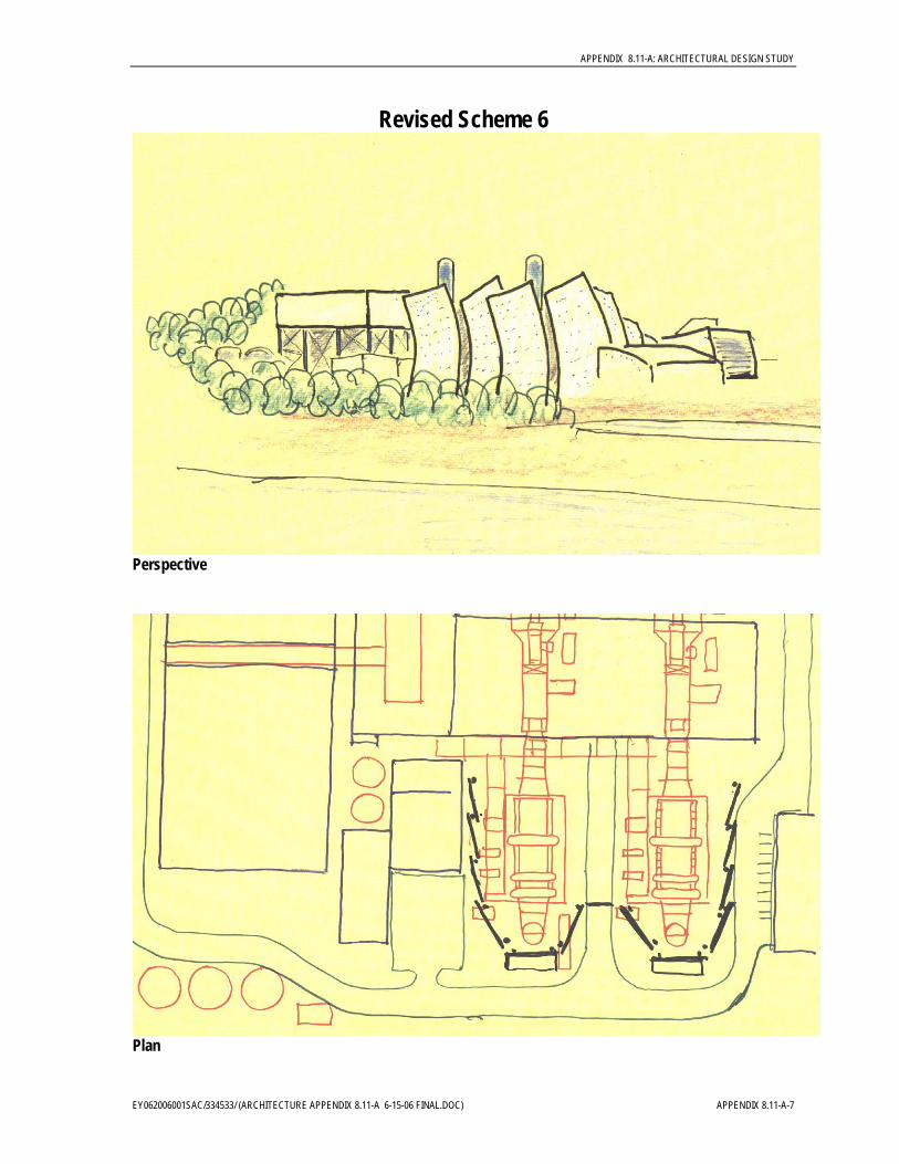
Revised Scheme 6 The main screens around the heat recovery steam generators are proposed to be constructed of stretched Teflon fabric panel, supported on a system of steel trusses. The fabric has good long-term durability and is self cleaning, so the material would remain unstained, and looking new for many years to come. As the material is translucent, in certain light conditions the plant equipment is partially visible through it.
The shape and material of these large screens is a deliberate evocation of sails, which is an appropriate visual simile given the plant’s waterside location. The free forms of the sails contrast with the orthogonal treatment of the turbine hall and the cooling tower, which are housed in an architectural enclosure that is rigorously neat and orderly. The end elevations of the turbine hall are subtly curved, to reflect the larger curved forms of the main screens.
The sculptured forms of the screens are articulated to further invoke the image of sailing boats, and their casual relationship to each other. However, the screen arrangements for each of the heat steam recovery generators are repeated, imposing a formal order over the informal association generated from the abstract shapes.
The most industrial looking parts of the entire plant are always the stacks. In this design, only the top of the stacks are left exposed, which is a functional requirement of emission control. The visible stacks can be painted a bright blue, the more easily to merge with a clear sky.. Revised Scheme 6 is depicted in the following four renderings.
APPENDIX 8.11-A: ARCHITECTURAL DESIGN STUDY
EY062006001SAC/334533/ (ARCHITECTURE APPENDIX 8.11-A 6-15-06 FINAL.DOC) APPENDIX 8.11-A-7
Revised Scheme 6
Perspective
Plan

APPENDIX 8.11-A: ARCHITECTURAL DESIGN STUDY
APPENDIX 8.11-A-8 EY062006001SAC/334533/ (ARCHITECTURE APPENDIX 8.11-A 6-15-06 FINAL.DOC)
Revised Scheme 6
Aerial
Elevation

APPENDIX 8.11-A: ARCHITECTURAL DESIGN STUDY
EY062006001SAC/334533/ (ARCHITECTURE APPENDIX 8.11-A 6-15-06 FINAL.DOC) APPENDIX 8.11-A-9
Revised Scheme 7 In this scheme, the screens form large sculpturally coherent shapes, which curve to follow the essential shape of the plant behind. The strong shape of the screening is a deliberate attempt to provide forms that are highly individual and patently non-functional, in order to act as a foil to the intrinsically functional nature of the plant itself. The utilitarian plant is made more accessible through being accompanied by a comprehensible work of three dimensional industrial art, albeit on a very large scale.
The structure for the screens is tilted forward at an angle of about 15 degrees. This device gives a sense of motion to the overall form. It is in step with the general theme of providing a contrasting foil to the mechanical plant equipment, as the tension of dynamic movement contrasts with the static verticality of the stacks. The fact that the structure leans forward is also counter intuitive, which reinforces the evidence for the screens as aesthetic installations rather than an adjunct to the process of power generation. Again, the intellectual exercise is invoked that juxtaposes the functional with the non-functional constituent components, the latter of which are purely and honestly applied solely for their visual appeal.
As with the previous schemes, the bases of the stacks are screened, but the top of the stacks are exposed, and can be painted in a bright and clean color. The main screening panel material can be either Teflon fabric or perforated stainless steel, as both are easily shaped into forms curved in three dimensions. Revised Scheme 6 is depicted in the following four renderings.

APPENDIX 8.11-A: ARCHITECTURAL DESIGN STUDY
APPENDIX 8.11-A-10 EY062006001SAC/334533/ (ARCHITECTURE APPENDIX 8.11-A 6-15-06 FINAL.DOC)
Revised Scheme 7
Perspective
Plan

APPENDIX 8.11-A: ARCHITECTURAL DESIGN STUDY
EY062006001SAC/334533/ (ARCHITECTURE APPENDIX 8.11-A 6-15-06 FINAL.DOC) APPENDIX 8.11-A-11
Revised Scheme 7
Aerial
Elevation

APPENDIX 8.11-A: ARCHITECTURAL DESIGN STUDY
APPENDIX 8.11-A-12 EY062006001SAC/334533/ (ARCHITECTURE APPENDIX 8.11-A 6-15-06 FINAL.DOC)
Scheme 8 The free flowing form of the main screening is split into four components, each of which flanks either side of the two heat steam recovery generators. Each of the four elements is reminiscent of the bow of a ship, and again, the maritime allusion is in keeping with the proximity of the South Bay. From a low level, from both the land and the sea, the image presented will be a row of sea-going vessels riding at anchor. However, as with all the other schemes, no attempt is made to camouflage or disguise the plant, and the stacks are exposed down to the ground, and can painted sympathetically.
As the cladding to the screens is curved only in two dimensions rather than three, the most appropriate material to cover the structural skeleton is perforated stainless steel, or stainless steel mesh. The structural supports for the screening and the dry cooling tower can be painted to match the stacks, providing a continuity of color throughout the plant. The screen structure is tilted forward, giving a steeply sloped forward part by the stacks, and straight sides. The screens are reduced in height towards the back of the generators, following the essential form of the equipment. Scheme 8 is depicted in the following four renderings.

APPENDIX 8.11-A: ARCHITECTURAL DESIGN STUDY
EY062006001SAC/334533/ (ARCHITECTURE APPENDIX 8.11-A 6-15-06 FINAL.DOC) APPENDIX 8.11-A-13
Revised Scheme 8
Perspective
Plan

APPENDIX 8.11-A: ARCHITECTURAL DESIGN STUDY
APPENDIX 8.11-A-14 EY062006001SAC/334533/ (ARCHITECTURE APPENDIX 8.11-A 6-15-06 FINAL.DOC)
Revised Scheme 8
Aerial
Elevation

APPENDIX 8.11-A: ARCHITECTURAL DESIGN STUDY
EY062006001SAC/334533/ (ARCHITECTURE APPENDIX 8.11-A 6-15-06 FINAL.DOC) APPENDIX 8.11-A-15
Potential Treatment Materials Various materials have been considered through the architectural study. A wide range of materials were considered in this early stage of the design process to allow for continued flexibility. Materials considered in the design study are described below. This list of materials is not meant to be all inclusive as other possible treatment options are available dependent and could be incorporated during the public involvement process. These are the materials that were recommended for the designs studied to-date.
Metal is one option that is used in the design schemes. Metal can be used as flat or corrugated panels, and both types of panel can be perforated. The panels can be matt finished stainless steel, painted, or galvanized. Panels can also be formed from stainless steel wire made into a mesh. Mesh and perforated panels can provide screening with a subtle transparency. An example of perforated metal is shown in the photo below.
Perforated Metal Example

APPENDIX 8.11-A: ARCHITECTURAL DESIGN STUDY
APPENDIX 8.11-A-16 EY062006001SAC/334533/ (ARCHITECTURE APPENDIX 8.11-A 6-15-06 FINAL.DOC)
Translucent fiberglass panels (Kalwall) are very sturdy and durable. This material can be used for the screening to the HRSG's and the ACCs.
Fiberglass fabric (Teflon) is a strong material, and can cover very large areas economically. It is flexible and easily shaped. It is translucent, and can be treated to provide a measure of acoustic attenuation. An example of fiberglass fabric is shown in the photo below.
Fiberglass Fabric Example
Original Architectural Study Schemes
The initial architectural study exercise completed by EDAW and Hillier Architecture included a total of seven different schemes that were designed to investigate a full range of potential treatment options. These schemes ranged from minimal frame enclosures to more stylized designs. The following renderings show the seven original study schemes that were designed and presented to the Ad Hoc Committee.

APPENDIX 8.11-A: ARCHITECTURAL DESIGN STUDY
EY062006001SAC/334533/ (ARCHITECTURE APPENDIX 8.11-A 6-15-06 FINAL.DOC) APPENDIX 8.11-A-17
Scheme 1

APPENDIX 8.11-A: ARCHITECTURAL DESIGN STUDY
APPENDIX 8.11-A-18 EY062006001SAC/334533/ (ARCHITECTURE APPENDIX 8.11-A 6-15-06 FINAL.DOC)
Scheme 2

APPENDIX 8.11-A: ARCHITECTURAL DESIGN STUDY
EY062006001SAC/334533/ (ARCHITECTURE APPENDIX 8.11-A 6-15-06 FINAL.DOC) APPENDIX 8.11-A-19
Scheme 3

APPENDIX 8.11-A: ARCHITECTURAL DESIGN STUDY
APPENDIX 8.11-A-20 EY062006001SAC/334533/ (ARCHITECTURE APPENDIX 8.11-A 6-15-06 FINAL.DOC)
Scheme 4

APPENDIX 8.11-A: ARCHITECTURAL DESIGN STUDY
EY062006001SAC/334533/ (ARCHITECTURE APPENDIX 8.11-A 6-15-06 FINAL.DOC) APPENDIX 8.11-A-21
Scheme 5

APPENDIX 8.11-A: ARCHITECTURAL DESIGN STUDY
APPENDIX 8.11-A-22 EY062006001SAC/334533/ (ARCHITECTURE APPENDIX 8.11-A 6-15-06 FINAL.DOC)
Scheme 6

APPENDIX 8.11-A: ARCHITECTURAL DESIGN STUDY
EY062006001SAC/334533/ (ARCHITECTURE APPENDIX 8.11-A 6-15-06 FINAL.DOC) APPENDIX 8.11-A-23
Scheme 7

APPENDIX 8.11-A: ARCHITECTURAL DESIGN STUDY
APPENDIX 8.11-A-24 EY062006001SAC/334533/ (ARCHITECTURE APPENDIX 8.11-A 6-15-06 FINAL.DOC)
This page intentionally left blank.