producingvirtualwalkthroughs from architectural models: a case study … · ·...
TRANSCRIPT

Bachelor Informatica
Producing Virtual Walkthroughsfrom Architectural Models: acase study of the New Univer-sity Building
Rowan de GraafE-mail: [email protected] ID: 6059031
June 17, 2015
Supervisor(s): dr. R.G. Belleman (UvA)
Signed:
Informatica—
Universiteit
vanAmst
erdam

2

Abstract
This thesis presents a workflow for the production of a Virtual Walkthrough from a given archi-tectural design. We identify a number of conversion and optimization steps needed to producea model suitable for a Virtual Walkthrough from a raw architectural data source. These stepsare connected in a workflow that iteratively optimizes the model until a level of performanceis attained. The workflow is evaluated in a case study of the New University building, in theform of a Virtual Walkthrough using the Oculus Rift head-mounted display. The constructedmodel closely resembles artistic impressions provided by the architects, while maintaining highperformance, resulting in a smooth and immersive user experience.

2

Contents
1 Introduction 5
1.1 Overview of this thesis . . . . . . . . . . . . . . . . . . . . . . . . . . . . . . . . . 6
2 Background & Related work 7
2.1 Origin . . . . . . . . . . . . . . . . . . . . . . . . . . . . . . . . . . . . . . . . . . 7
2.1.1 Virtual Walkthrough . . . . . . . . . . . . . . . . . . . . . . . . . . . . . . 7
2.2 Virtual Reality . . . . . . . . . . . . . . . . . . . . . . . . . . . . . . . . . . . . . 7
2.3 Applications . . . . . . . . . . . . . . . . . . . . . . . . . . . . . . . . . . . . . . . 8
2.3.1 General . . . . . . . . . . . . . . . . . . . . . . . . . . . . . . . . . . . . . 8
2.3.2 Architectural . . . . . . . . . . . . . . . . . . . . . . . . . . . . . . . . . . 9
2.3.3 Comparable research with this thesis . . . . . . . . . . . . . . . . . . . . . 9
2.4 Technology . . . . . . . . . . . . . . . . . . . . . . . . . . . . . . . . . . . . . . . 9
2.4.1 Software . . . . . . . . . . . . . . . . . . . . . . . . . . . . . . . . . . . . . 9
2.4.2 Architectural data sources . . . . . . . . . . . . . . . . . . . . . . . . . . . 10
2.4.3 Interaction with Virtual Reality . . . . . . . . . . . . . . . . . . . . . . . . 10
2.4.4 Movement in Virtual Reality . . . . . . . . . . . . . . . . . . . . . . . . . 10
2.4.5 Vision in Virtual Reality . . . . . . . . . . . . . . . . . . . . . . . . . . . . 11
3 Design 13
3.1 Context . . . . . . . . . . . . . . . . . . . . . . . . . . . . . . . . . . . . . . . . . 13
3.2 Components . . . . . . . . . . . . . . . . . . . . . . . . . . . . . . . . . . . . . . . 13
4 Case Study 17
4.1 The NU Project . . . . . . . . . . . . . . . . . . . . . . . . . . . . . . . . . . . . 17
4.2 Technical goals . . . . . . . . . . . . . . . . . . . . . . . . . . . . . . . . . . . . . 18
5 Evaluation 19
5.1 Optimize modifier . . . . . . . . . . . . . . . . . . . . . . . . . . . . . . . . . . . 19
5.2 Weld modifier . . . . . . . . . . . . . . . . . . . . . . . . . . . . . . . . . . . . . . 20
5.3 Model finalization & Performance . . . . . . . . . . . . . . . . . . . . . . . . . . . 20
5.4 Software product . . . . . . . . . . . . . . . . . . . . . . . . . . . . . . . . . . . . 21
5.5 Summary of results . . . . . . . . . . . . . . . . . . . . . . . . . . . . . . . . . . . 21
3
6 Discussion & Future work 23
6.1 Discussion . . . . . . . . . . . . . . . . . . . . . . . . . . . . . . . . . . . . . . . . 23
6.2 Future work . . . . . . . . . . . . . . . . . . . . . . . . . . . . . . . . . . . . . . . 24
7 Conclusion 25
7.1 Summary . . . . . . . . . . . . . . . . . . . . . . . . . . . . . . . . . . . . . . . . 25
7.2 Research question . . . . . . . . . . . . . . . . . . . . . . . . . . . . . . . . . . . . 25
7.3 Application . . . . . . . . . . . . . . . . . . . . . . . . . . . . . . . . . . . . . . . 25
Appendices 27
A Graphical comparison of the result and artistic impression 29
4

CHAPTER 1
Introduction
With today’s increasing interest in Virtual Reality a wide variety of applications come to mind.VR is used for training in the army[28], entertainment purposes for flights[9] and exploration ofareas[16]. We explore the use of a Virtual Walkthrough (VW) to explore architectural designs.A VW offers an immersive experience that improves spatial awareness with respect to a two-dimensional artistic impression[21]. We identify at least the following categories of simulationsthat can be enhanced by application of a VW:
• ArchitecturalThe perspective offered by a VW helps in the discovery of design flaws. For example, aninconveniently positioned pillar is more easily discovered when bumping into it during asimulation, than when looking at a blueprint.
• PositioningThe positioning of a building combined with its unique design might cause problems. Ifsolar simulations would have been used prior to building London’s “Walkie-Talkie”[19] theywould have noticed that the unique form of the building caused the incoming sun rays tobe bundled and projected down on the street on one spot.
• Interior fillingComplex spaces within buildings can be filled by computer algorithms. This way the wishesof the owner produce a best-fit for the interior design (desk placement). Not only can thisbe used for the spacial interior design but also for example the placement of employeeswithin a building[7].
Before a Virtual Walkthrough of a building can be developed, a suitable computational model ofthe architecture needs to be available. The source of choice for any architectural project will bethe architect. The format and complexity of the source data supplied by architects differ fromthose required by current software that is used to create Virtual Walkthroughs. In this work, wepresent a workflow which enables us to bridge this gap. In the process, we answer the followingquestion:
• Are data sources produced by architects suitable for “virtual walkthrough” simulations,and if so; what is necessary to produce such a simulation?
As a test case, this thesis takes the “New University” (NU) building, the proposed new home ofthe Information Sciences departments of UvA and VU, the construction of which has started in2014 and will be finished in 2018.
5

1.1 Overview of this thesis
This thesis finds it foundation in the workflow of a certain process, a recipe it might even becalled. Below is the structure of this thesis.
• Chapter 2 provides background information regarding Virtual Walkthroughs, Virtual Re-ality and its technology. Furthermore related work concerning these two fields is discussed.
• Chapter 3 provides the design upon which the workflow is constructed.
• Chapter 4 provides a case study and the technical goals imposed on this project.
• Chapter 5 provides an evaluation of the results after application of the workflow on thecase study.
• Chapter 6 provides a discussion in which other solutions are explored and a proposal forfuture work.
• Chapter7 provides the conclusion of this thesis which consists of a summary, the proposedresearch question and further application of this thesis’s work.
• Finally, AppendixA provides a comparison of the evaluated results and its correspondingartistic impressions.
6

CHAPTER 2
Background & Related work
This section is based on the explanation of the cornerstones upon which this thesis is build, thatof Virtual reality and Virtual walkthroughs.
2.1 Origin
2.1.1 Virtual Walkthrough
A virtual walkthrough (VW) is the term for exploring a virtual environment (VE). The VW’sare realized with the use of Virtual Reality (VR) environments. In a VW the user is equippedwith a head-mounted display (HMD) and/or peripheral devices which can control movement. Inthis setup the user’s sense of vision is “fooled” by receiving stimuli from the HMD. A whole newreality is created and the user is emerged in the VE.
The first use of a VW that we know of is by I.Sutherland in 1968[26], who was able to explorea wireframe room using an HMD. The first public application of a VW was a 3D reconstructionof the Dudley Castle in England as it was in 1550.[16]
With the use of VWs users can experience areas which they could previously not (think of areaswhich require travelling). Not only areas which already exist in the real world but also areaswhich do not even exist yet. We focus on the latter, in the light of our focus on architecturaldesign.
2.2 Virtual Reality
A Virtual Walkthrough is an application of Virtual Reality (VR). VR replicates an environmentthat simulates a physical presence in either the real world or one self designed. Within this worldsenses such as touch, vision and sound can be emulated for the user, based on the VE. The term“VR”, coined by J. Lanier in 1987 was interchangeably used with the term “VE”. It was not untilafter the article “Defining Virtual Reality: Dimensions Determining Telepresence” written by J.Steuer[24] before VR and VE got their own definitions and applications of one could properly benamed.
VR found its origin in the research field. The first application of VR with the HMD developed byI. Sutherland was one which had to be supported by the ceiling. The HMD was ahead of its timeand the application of VR was limited by the technology on which it was used. It was not until1991 in which the first construction of the Cave Automatic Virtual Environment (CAVE) wasfinished at the Electronic Visualization Laboratory. The CAVE is a multi-person, room-sized,high-resolution 3D video and audio environment.[10]
7

(a) HMD created by Ivan Sutherland. The HMDhad to be supported from the ceiling.
(b) An exterior view of the CAVE. A virtual expe-rience made bossible by box rojection.
Figure 2.1: Various VR concepts.
Developments in the area of VR have taken a big leap in the past years making VR moreaccessible to the masses. The Oculus Rift Development Kit 1 in 2012 started a rivalry whichled to the development of multiple HMD’s. Computers are now capable of running sophisticatedVR simulations and the hardware has become so small that a HMD can now be worn withoutany supportive structures. Therefore, making them popular with the public.
2.3 Applications
2.3.1 General
VR - What’s Real About Virtual Reality?
F.Brooks wrote an article[6] reporting on the real progress of VR. By many sources it was claimedthat VR “Almost worked” but in practice it seemed that a lot of the applications worked barely.The most challenging part concerning the use of VR was the end-to-end latency of the systemsused in the simulations. Immersion in VR takes a great hit due to this end-to-end latency causestimuli needs to be on point and expected by the brain. Some of the big challenges back in 1994were the rendering of models with more than 1M polygons and choosing which display suitedthe application best: HMD, Panorama, Cave.
VW - Archaeology, museums and virtual reality
L. Pujol wrote an article[18] which explains the use of VR and VW based on archaeology andcultural origin. The article further discusses whether VR can be used as a proper representationof archaeological finds. It is concluded that VWs based on archaeological finds are sophisticatedenough to be used for archaeological purposes as well as cultural applications in museums.
8

2.3.2 Architectural
VR - From CAD to virtual reality: modelling approaches, data exchange and interactive 3D buildingdesign tools
The research done by A.Thorpe et al in this paper[13] is based on the connection of architecturaldesign and VR. It compares the use of Virtual Reality Modeling Language (VRML)[30] withinCAD to the manual method in 3D Studio VIZ [25]. Concluded within the paper is that straightconversion of CAD models to VRML gives inconsistent results and a more manual approachusing 3D Studio Viz is favorable.
VW - Research on 3D Reality-based Modeling and 3D Virtual Walkthrough for Cultural ArchaeologicalSites.
This[12] case study was based on mapping the architectural structure a specific cultural site inthis case “The Small Wild Goose Pagoda” in the Tang Dynasty. This study presents a methodin which laser scanning is combined with photography. This method proves to be effective increating 3D models based of existing constructions. These scanned constructions are later usedfor application within VWs.
2.3.3 Comparable research with this thesis
VR - Virtual Office Walkthrough Using a 3D Game Engine
The research done in this paper is a workflow in which they create a model from 2D drawingsin a gaming engine[22]. Though due to the technical limits set by that time the result producedwas not satisfactory. The game engine used Unreal Engine 2 and has a limit of 30 FPS. Since asmooth VR experience requires at least 60FPS (30FPS per eye) the workflow described in thispaper is less suitable for the usage in VR.
VR/VW - Users’ evaluation of a virtual reality architectural model compared with the experience ofthe completed building
This paper described the architectural use of VR models to inform their future employees[31].Results of the paper pointed out that VR can be used to give an accurate example of a yet-to-be-build construction.
2.4 Technology
2.4.1 Software
Whenever we separate linear explorable 360 degree pictures from actual 3D interactive modelsa couple of software packages come to mind. Model-and-walkthrough software packages suchas Sketchup[23], Rhino[20], allows the user to create 3D models and have a VW through them.Even HMD’s can be used in some of these software packages.
More complex 3D interactive model simulations can be created in gaming engines such as UnrealEngine4 and Unity. Mostly these gaming engines are used in combination with 3D modellingsoftware such as 3DSMAX[3], Rhino, Blender[4] and others. The use of a gaming engine withinthis aspect allows the user to actually partake in a VW since the 3D model software itself doesnot support this.
9

2.4.2 Architectural data sources
Architects use software which is specifically developed for designing buildings.Black spectacles,home of e-learning courses regarding architecture and design[27] conducted research over 900job opportunities for architectural jobs within the top 50 companies active in architecture. Theresults conclude that from the 900 jobs 71% require knowledge of Revit[11], 50% of AUTOCAD[2]and 35% of Sketchup. None of these programs support out of the box interactive 3D modelproduction.
Models produced by these programs contain all information about a building whether its thethermal packaging or the double glass windows. All this information is not needed for examplewith a graphical representation of a building. Therefore the data supplied by architects, whetherit be a 2D drawing or a special architectural design format, it is not suitable for generating anout of the box 3D computer model.
2.4.3 Interaction with Virtual Reality
The Leap motion controller
The Leap motion[14] is a small device which is able to detect hand movement in a small specificarea. Interaction with the leap does have downsides while in a VW due to the small area inwhich the Leap is used. Therefore only specific simulations which keep the real world placementof the leap in mind are able to benefit from its features.
Figure 2.2: In the left picture displayed is the original use case for the Leap. The right picturepresents a modification to the HMD which makes use of the Leap in VWs more suitable.
2.4.4 Movement in Virtual Reality
Virtuix Omni
When a VW is conducted, motion tracking can be used to simulate movement in the VW. Usingthis way of tracking means the explorable area in VW needs to be smaller or equal to the size ofthe real world space. This limits the use of exploration in VW.
This is the problem for which the Virtuix Omni[29] was developed as a solution. This omnidi-rectional treadmill makes 360 degree movement possible without changing your own position inthe real world.
10
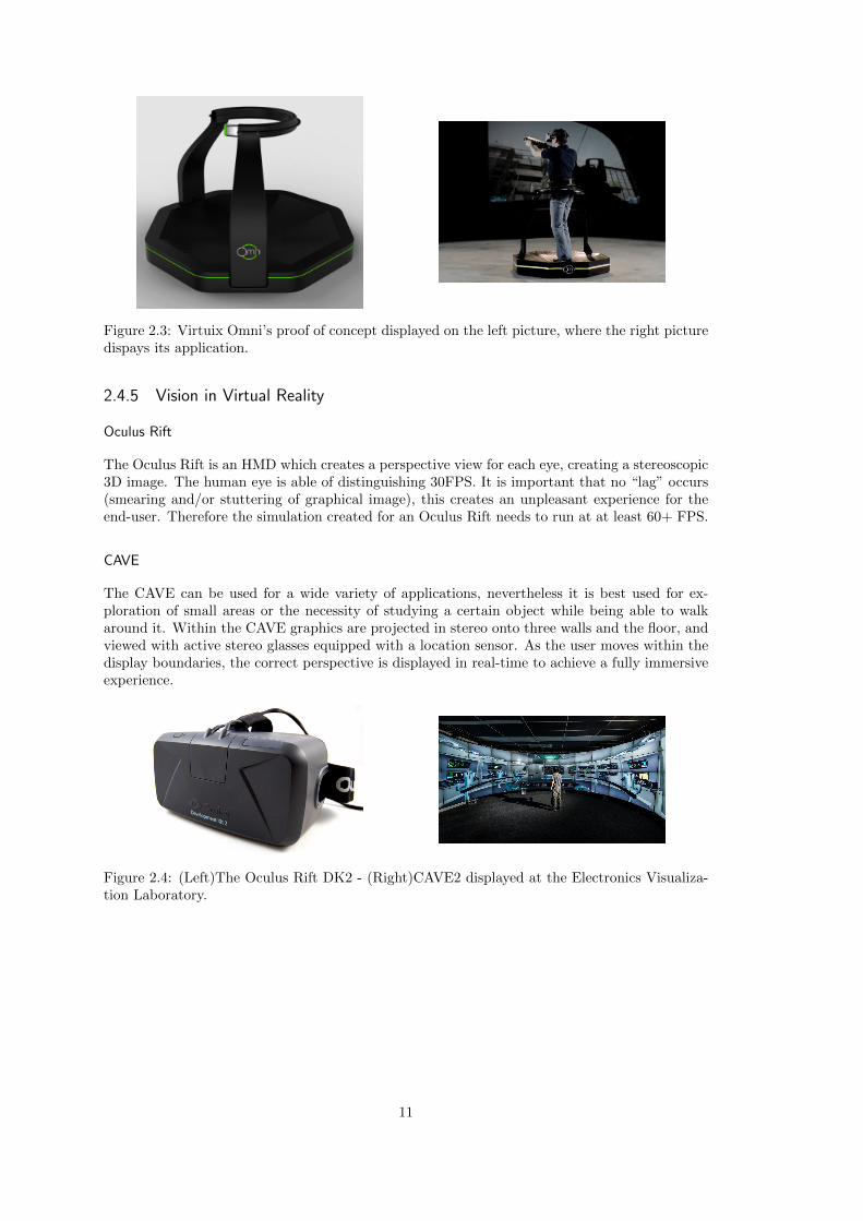
Figure 2.3: Virtuix Omni’s proof of concept displayed on the left picture, where the right picturedispays its application.
2.4.5 Vision in Virtual Reality
Oculus Rift
The Oculus Rift is an HMD which creates a perspective view for each eye, creating a stereoscopic3D image. The human eye is able of distinguishing 30FPS. It is important that no “lag” occurs(smearing and/or stuttering of graphical image), this creates an unpleasant experience for theend-user. Therefore the simulation created for an Oculus Rift needs to run at at least 60+ FPS.
CAVE
The CAVE can be used for a wide variety of applications, nevertheless it is best used for ex-ploration of small areas or the necessity of studying a certain object while being able to walkaround it. Within the CAVE graphics are projected in stereo onto three walls and the floor, andviewed with active stereo glasses equipped with a location sensor. As the user moves within thedisplay boundaries, the correct perspective is displayed in real-time to achieve a fully immersiveexperience.
Figure 2.4: (Left)The Oculus Rift DK2 - (Right)CAVE2 displayed at the Electronics Visualiza-tion Laboratory.
11

12

CHAPTER 3
Design
3.1 Context
The workflow created in this thesis is based on the source data supplied by architects and thehardware available for this research. Supplied by the University of Amsterdam is an Oculus Rift,this is used as the HMD for the VWs. Movement and other interaction is done by the use of anXbox 360 Controller[32].
Using the Oculus Rift imposes certain performance requirements. Performance is impacted bythe polygon/vertex count of a model and the environment created for the VW[1]. The gameengines which support the Oculus Rift are Unreal Engine 4 (UE4) and Unity. Due to the opensource origin of UE4 and its free licensing UE4 is used for this project. This choice does notaffect the designed workflow since the best supported import format of both programs is FBX[5].
The input used for this workflow is that of the Revit format, due to its popularity within thearchitecture and design sector as pointed out in Section 2.4.2. Revit is used either to design, orjoin 2D designs of a building. The output of the workflow will be that of the FBX format sinceit is broadly supported by both game engines.
3.2 Components
Generating a 3D model straight from a Revit format results in a complex computational model.The geometric shapes shown in this 3D-model are very realistic. This is due to the level of detailneeded in the construction of a building. Importing these models directly into a gaming engineresults in a poor performance.
Since the direct conversion of the Revit format results in poor performance, the model needs tobe optimized. Optimization of the model is done by 3D modelling software. For this purposea variety of programs can be used such as 3DSMAX, Rhino and Blender. We use 3DSMAX.The purpose of this step is to reduce the amount of detail in the 3D model generated by Revit.This is achieved by modifying the polygon/vertex structure of the model, effectively reducing thecomplexity of the model with the use of the weld modifier. Especially rounded objects benefitfrom this step due to their creation by approximating π (see Figure 3.1).
Exporting the optimized model to FBX generates an acceptable file for the gaming engine. Allindividual items which are found in the FBX file are imported as single meshes. Big architec-tural buildings could easily contain two million individual items, therefore two million indicidualmeshes would be created. No game engine is capable of contain that amount of meshes. FOrthis reason the meshes need to be grouped, based on either type, manufacturer or material. TheCollada format is based on creating meshes based on materials. Therefore an export in Colladaformat from Revit is required.
13
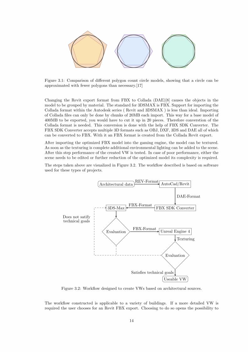
Figure 3.1: Comparison of different polygon count circle models, showing that a circle can beapproximated with fewer polygons than necessary.[17]
Changing the Revit export format from FBX to Collada (DAE)[8] causes the objects in themodel to be grouped by material. The standard for 3DSMAX is FBX. Support for importing theCollada format within the Autodesk series ( Revit and 3DSMAX ) is less than ideal. Importingof Collada files can only be done by chunks of 20MB each import. This way for a base model of400MB to be exported, you would have to cut it up in 20 pieces. Therefore converstion of theCollada format is needed. This conversion is done with the help of FBX SDK Converter. TheFBX SDK Converter accepts multiple 3D formats such as OBJ, DXF, 3DS and DAE all of whichcan be converted to FBX. With it an FBX format is created from the Collada Revit export.
After importing the optimized FBX model into the gaming engine, the model can be textured.As soon as the texturing is complete additional environmental lighting can be added to the scene.After this step performance of the created VW is tested. In case of poor performance, either thescene needs to be edited or further reduction of the optimized model its complexity is required.
The steps taken above are visualized in Figure 3.2. The workflow described is based on softwareused for these types of projects.
Architectural data AutoCad/Revit
FBX SDK Converter3DS-Max
Evaluation Unreal Engine 4
Evaluation
Useable VW
REV-Format
DAE-Format
FBX-Format
FBX-Format
Texturing
Does not satifytechnical goals
Satisfies technical goals
Figure 3.2: Workflow designed to create VWs based on architectural sources.
The workflow constructed is applicable to a variety of buildings. If a more detailed VW isrequired the user chooses for an Revit FBX export. Choosing to do so opens the possibility to
14

use static lighting. Static lighting in big constructions is not possible due the unwrapping stagein the gaming engine.
An object’s UV channel stored the texture properties. Using static lighting enables the user toadd complex lighting sources to his environment. The use of complex light sources and its effects(shadows). After “calculating” the effect of the light sources on its environment the informationcan be stored into the texture. This way no computation is done regarding lighting during thesimulation. The storing of these textures is done in 2D images. Exporting the file to a Colladaformat creates big meshes which contain all items with the same material. These big meshes cannot be unwrapped into 2D images. Therefore, static lighting is not possible in some cases.
15

16
CHAPTER 4
Case Study
4.1 The NU Project
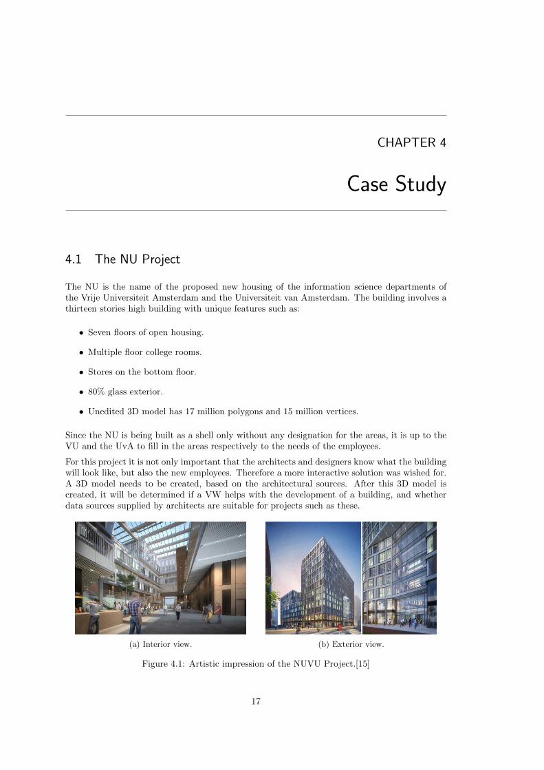
The NU is the name of the proposed new housing of the information science departments ofthe Vrije Universiteit Amsterdam and the Universiteit van Amsterdam. The building involves athirteen stories high building with unique features such as:
• Seven floors of open housing.
• Multiple floor college rooms.
• Stores on the bottom floor.
• 80% glass exterior.
• Unedited 3D model has 17 million polygons and 15 million vertices.
Since the NU is being built as a shell only without any designation for the areas, it is up to theVU and the UvA to fill in the areas respectively to the needs of the employees.
For this project it is not only important that the architects and designers know what the buildingwill look like, but also the new employees. Therefore a more interactive solution was wished for.A 3D model needs to be created, based on the architectural sources. After this 3D model iscreated, it will be determined if a VW helps with the development of a building, and whetherdata sources supplied by architects are suitable for projects such as these.
(a) Interior view. (b) Exterior view.
Figure 4.1: Artistic impression of the NUVU Project.[15]
17
4.2 Technical goals
For this experiment to be a success a set of technical goals have been determined:
Create an interactive model of the NU building.To be able to do a VW in VR we need a 3D model of the building. The software used bythe architects (Revit, Autocad, Sketchup) do not have a built in feature to generate a VWsuitable interactive model.
The interactive model must be viewable with an Oculus Rift.The Oculus Rift is used as HMD for the VR part of this project. Therefore, we need touse software which is able to render to an Oculus Rift.
The interactive model must run at at least 60 frames per second (FPS).Since the human eye is able to perceive 30FPS per eye and the Oculus Rift generates astereoscopic image the total framerate of the final simulation need to be at least 60FPS.If this threshold is not met, smearing of the graphical image could create a less optimalexperience for the user. Important is that a resulting model with a FPS of lower than 60FPScould still be an accepted model since only the experience suffers from this technologicallimit.
All thirteen floors need to be implemented in the model.With regards to the research question whether the VW helps the development of a building,it is important that the VW resembles the same experience as the real building. For thisreason alone it is important that all thirteen floors are properly displayed at once.
The model needs to look realistic, textures are a necessity.The VW will be used to instruct employees about the building therefore it needs to lookrealistic. Since VWs are not generally used and neither are normal 3D models, normalgrey blocks reduce the perception of the end-user due to lack of definition. Using texturesmakes perception easier and more realistic to the end-user.
The model must be realized by a definable workflow.Every object in reality can be modeled into a 3D model by hand. The workflow described inthis thesis is one that needs to be applicable on architectural drawings in general. Therefore,a small portion of the process may be done by hand but the workflow needs to be focusedon usage on an autonomic scale.
18
CHAPTER 5
Evaluation
5.1 Optimize modifier
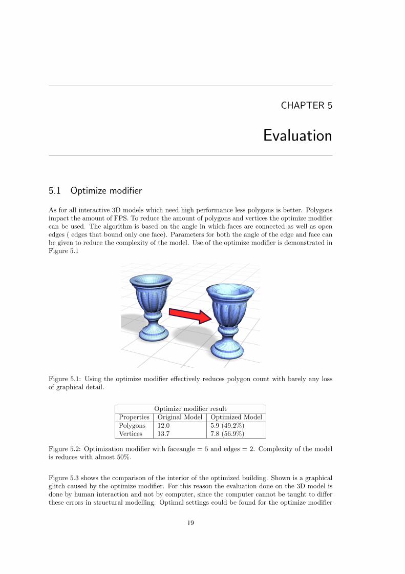
As for all interactive 3D models which need high performance less polygons is better. Polygonsimpact the amount of FPS. To reduce the amount of polygons and vertices the optimize modifiercan be used. The algorithm is based on the angle in which faces are connected as well as openedges ( edges that bound only one face). Parameters for both the angle of the edge and face canbe given to reduce the complexity of the model. Use of the optimize modifier is demonstrated inFigure 5.1
Figure 5.1: Using the optimize modifier effectively reduces polygon count with barely any lossof graphical detail.
Optimize modifier resultProperties Original Model Optimized ModelPolygons 12.0 5.9 (49.2%)Vertices 13.7 7.8 (56.9%)
Figure 5.2: Optimization modifier with faceangle = 5 and edges = 2. Complexity of the modelis reduces with almost 50%.
Figure 5.3 shows the comparison of the interior of the optimized building. Shown is a graphicalglitch caused by the optimize modifier. For this reason the evaluation done on the 3D model isdone by human interaction and not by computer, since the computer cannot be taught to differthese errors in structural modelling. Optimal settings could be found for the optimize modifier
19

(a) Original model. (b) Modified model.
Figure 5.3: Using the Optimize modifier excessively causes errors in the model.
but with big constructions the calculation time of the model can take up hours (Applying thismodifier on the test case took 19 hours), therefore a more manual approach is wished for.
5.2 Weld modifier
3DSMAX’s Weld modifier merges a specified amount of vertices into one vertex if the distancebetween those vertices are lower than a specified threshold. The goal is to find values for theseparameters such that the complexity of the model is reduced as much as possible, while stillmaintaining a certain level of graphical quality. Due to differences in shape, some objects allowfor a higher level of optimization than others. If the same parameters are used for the wholemodel, optimization is restricted to the level of the least optimizable object (i.e. the object thatcannot be optimized further without losing an unacceptable level of graphical quality). Table 5.4shows that a more fine-grained selection of parameters yields a substantially higher reduction incomplexity.
Weld modifier model comparisonProperties Original Model Uniform parameters Fine-grained parametersPolygons (M) 12.0 11.9(99.2%) 3.8 (31.7%)Vertices (M) 13.7 10.6 (77.4%) 5.2 (37.9%)
Figure 5.4: Number of polygons and vertices before and after application of the weld modifier.Uniform parameters yield only a 0.8% reduction as opposed to 68.3% when using a fine-grainedapproach.
5.3 Model finalization & Performance
After finding the most suitable model for creating a VE, lighting and textures are applied withinUE4. Applying the textures to the meshes is done by hands since the original model did nothave any textures. With respect to the realistic feeling of the VW textures have been chosenwhich are comparable to the artistic impression supplied by the architectural bureau.
Since static lighting can not be used, a dynamic skylight is introduced. Its sole purpose is theambient lighting of all objects since there is no shadow or interaction with the light itself.
The VW created seems one of additional value. The artistic impression by the architecturalbureau consist of 8 pictures and a small animation real of the central two floors. With this VWinterested parties can experience the building. Not only can this VW be used to look at conceptswhich are already in place for when the project is being built, but also to create new ones.
20
The comparison results between the product created with the use of the workflow applied to thecase study and its artistic interpretation can be found in Appendix A.
The VW was tested on a machine with an Intel i7 2600K processor and an ATI R9 290X graphicscard, running at 195-215 FPS. Although this can be considered a high-end gaming system, thesenumbers indicate that a medium-end desktop computer will likely be able to attain 60FPS. Wealso tested the VW on a laptop with an Intel i7-4750HQ processor and an Intel Iris Pro Graphics5200 graphics card, running at 28-35 FPS. While this is too low for use with the Oculus Rift,one can not expect a complex VW such as this to run at full performance on a laptop. Herebywe conclude that the technical goal of 60FPS was met.
5.4 Software product
For this project the following programs were used:
Revit 2016Revit is used for opening the source file, selecting what parts of the building to be exported.Source:12274-NU.VU-20140901.rvtProduced:NUVU-GeometryMax-Full.DAE
FBX SDK Converter 2013The converter is used for transforming the DAE file to FBX.Source:NUVU-GeometryMax-Full.DAEProduced:NUVU-GeometryMax-Full.FBX
3DSMAX 20163DSMax is used to optimize the FBX model efficiently reducing its amount of polygons.Source:NUVU-GeometryMax-Full.FBXProduced:NUVU-GeometryMax-Full-Weld.FBX
Unreal Engine 4 - v4.8The Unreal engine is used for creation of the virtual environment. This includes meshplacement, environmental lighting and texturing.Source:NUVU-GeometryMax-Full.FBXProduced:NUVU Project (Directory) 920MB in size.
5.5 Summary of results
After application of the workflow onto the source file of the NU Project a VW is created. TheVW created satisfies all technological goals imposed by the project. The visual representation ofthe model required some manual labor. This due to no textures being present (except for claycolours) in the source model. Application of custom textures took 2 hours, including lighting.With these results it is concluded that the workflow works for an architectural structure of greatsize.
21

22
CHAPTER 6
Discussion & Future work
6.1 Discussion
Creating a VW from a building is not a linear task. Even though a VW can be created fromcertain data sources produced by architects a lot of optimization needs to be done. The resultingVW created in the process can be used to create a spatial image for the user, mostly becauseartistic impressions do not cover every single aspect of a building.
Certain optimizations by UE4 could not be used due to the way the data of the 3D model wasorganized. Creating an FBX format from the Revit file instead of a DAE file format wouldhave taken a longer time to texture. If a 3D model which was already textured could have beenexported from Revit the time spent texturing would have been lower. With these small meshesa feature called culling could have been used. Culling prevents UE4 of rendering specified sizedof objects whenever they are to far from the camera. In contrary to our resulting VW whereeverything is rendered. The reason why culling does not work in the thesis specified workflowis due to the usage of the DAE format. The DAE format produces large meshes which containall the objects with the same material. Since a small portion of the mesh will always be close tothe renderpoint in the VW, culling can not occur. The use of culling could drastically improveperformance.
The workflow specified in this thesis uses dynamic lighting in contrary to static lighting. Theuse of static lighting was not possible with the use of the DAE format. The reason lies in theway static lighting works. Whenever you create an object in 3D it has a property called “UV-Channels”. These UV channels contain the information in which the texture is saved and howlighting affects it. Whenever in a static lighting environment lighting is created, it is build forthe current scene. This way the 3D software saves the “way” of how the light affects a certainobject. Unwrapping of these UV-channels is a heavy task and a resourceful one. Texturing a3D model correctly would mean to first assign textures, then render lighting. After this processis done the result, a texture with lighting on it, is saved to a renderfile. Texture renders suchas these have a specific resolution. Unwrapping big meshes produced by the DAE format wouldresult in very low detail UV unwraps, since all polygons need to be fitted within a 2048p x 2048ptexture render (an already somewhat bigger size).
Nevertheless the choice for DAE was made due to the fact that the process had to be mainlyautomated and as less manual work as possible. We do believe that the results acquired withinthis project are one of the best considering the alternatives.
23

6.2 Future work
In the introduction of this thesis notions were made in regard to certain types of simulations.The result produced by this thesis is a cornerstone for some of these simulations thus furtherresearch can be done in this field.
For some of the simulations described in the introduction the model produced may not be asvaluable. This is due to the type of computer model the result became. Simulations such asescape routes, people mass analysis may proof to be more effective on a less dimensional andgraphical representation of the model. Nevertheless fire simulations for example or optimal useof space for interior design, do benefit from the graphical and higher dimensional representationof this model.
24

CHAPTER 7
Conclusion
7.1 Summary
The creation of a VW from an architectural data source is not a trivial task. After constructionof a general workflow for this task it is applied to the case study. The result, an optimized 3Dmodel, can be imported in a game engine that supports VW. After the creation of the virtualenvironment with the optimized model the VW is evaluated. The result is a smooth experiencewhich closely matches the artistic impression provided by the architectural bureau.
7.2 Research question
Are data sources produced by architects suitable for “virtual walkthrough” simulations,and if so;what is necessary to produce such a simulation?
Raw data sources supplied by architects are not a suitable sources for VWs. In order to makethem suitable a number of conversion and optimization steps are required. The level of opti-mization that is required depends on the size of the input model. For smaller models, someoptimization steps may be omitted if performance is sufficient. The workflow described in thisthesis includes an iterative component that optimizes until acceptable performance is attained.The resulting model is then used in the gaming engine for the creation of the VW.
7.3 Application
The VW produced from the NU Project can be used for informing employees of the Universityof Amsterdam and the Vrije Universiteit. Displaying the VW can not only be done with the useof an HMD but also with the normal use of a monitor. Any suggestions or questions regardingthe building can then be discussed with the contractor, providing feedback in an early stage ofthe building process.
Furthermore, the workflow designed in this thesis can be for other projects that use the Revitformat. We believe we have lowered the bar for the integration of VWs in architectural design.
25

26

Appendices
27


APPENDIX A
Graphical comparison of the result andartistic impression
29
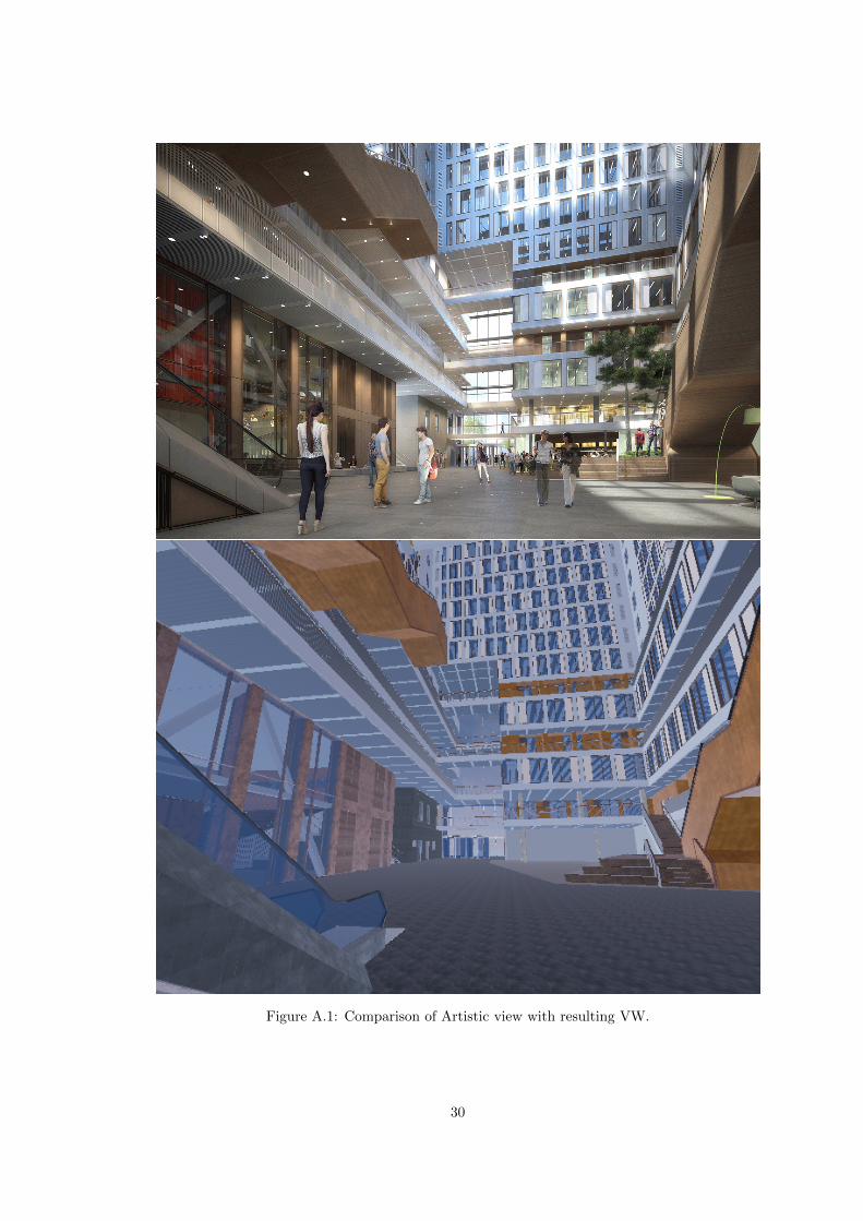
Figure A.1: Comparison of Artistic view with resulting VW.
30
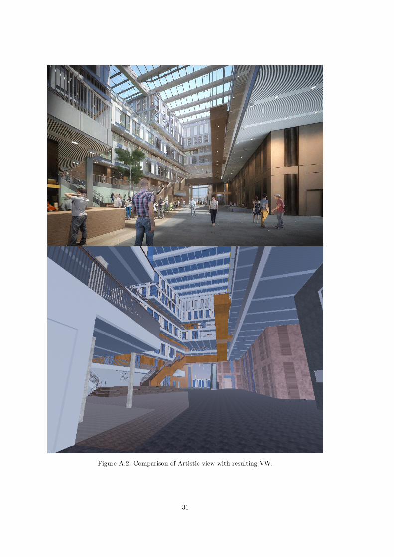
Figure A.2: Comparison of Artistic view with resulting VW.
31

Figure A.3: Comparison of Artistic view with resulting VW.
32

Figure A.4: Comparison of Artistic view with resulting VW.
33

Figure A.5: Comparison of Artistic view with resulting VW.
34

Bibliography
[1] Beautiful, yet friendly part 1: Stop hitting the bottleneck. Game Developer magazine, jun2003.
[2] Autodesk – Autocad. http://www.autodesk.com/products/autocad/overview, 2015.
[3] Autodesk 3DSMAX. http://www.autodesk.com/products/3ds-max/overview, 2015.
[4] Blender. https://www.blender.org/, 2015.
[5] Blender. https://code.blender.org/2013/08/fbx-binary-file-format-specification/,2015.
[6] Frederick P. Brooks. What’s real about virtual reality? IEEE Comput. Graph. Appl.,19(6):16–27, November 1999.
[7] Marc Buijsman. Interactieve Visuele Constraint Based Optimization : een user interfacevoor het FNWI ruimte-indelingsprobleem. Bachelor thesis, Universiteit van Amsterdam,2010.
[8] Collada. https://www.khronos.org/collada/wiki/Main_page, 2015.
[9] DailyMail – Qantas to give first class passengers virtual reality head-sets. http://www.dailymail.co.uk/sciencetech/article-2932113/
Forget-flight-film-Quantas-class-passengers-virtual-reality-headsets.html,2015.
[10] Electronic Visualization laboratory – The Cave. https://www.evl.uic.edu/cave, 1992.
[11] Autodesk Revit Family. http://www.autodesk.com/products/revit-family/overview,2015.
[12] Guo-hua GENG, Jun LIU, and Xue-song WANG. Research on 3d reality-based modeling and3d virtual walkthrough for cultural archaeological sites. Science of Surveying and Mapping,29(5):69–71, 2004.
[13] A. Thorpe R. McCaffer J. Whyte, N. Bouchlaghem. From cad to virtual reality: modellingapproaches, data exchange and interactive 3D building design tools. 1999.
[14] Leap Motion. https://www.leapmotion.com/, 2015.
[15] Description of the NU.VU building Team V Architects. http://www.archello.com/en/
project/nuvu-multifunctional-university-building#, 2015.
[16] Imaging The Past. Susan s. lukesh. CSA Newsletter, Vol. VII, No. 4, feb 1995.
[17] Kalid Azad Prehistoric Calculus: Discovering Pi. http://betterexplained.com/
articles/prehistoric-calculus-discovering-pi/, 2015.
35

[18] Pujol - Archaeology, museums and virtual reality. http://www.uoc.edu/humfil/articles/eng/pujol0304/pujol0304.pdf, 1992.
[19] Reuter. http://www.livescience.com/39371-skyscraper-melts-cars-20-fenchurch.
html, 2013.
[20] Rhinoceros. https://www.rhino3d.com/, 2015.
[21] Marc A Schnabel and Thomas Kvan. Spatial understanding in immersive virtual environ-ments. International Journal of Architectural Computing, 1(4):435–448, 2003.
[22] Mohd. Fairuz Shiratuddin and Walid Thabet. Virtual office walkthrough using a 3D gameengine. International Journal of Design Computing, 4:4, 2002.
[23] Sketchup - 3D for Everyone. http://www.sketchup.com/, 2015.
[24] Jonathan Steuer. Defining virtual reality: Dimensions determining telepresence. JOURNALOF COMMUNICATION, 42:73–93, 1992.
[25] StudioVIZ. http://www.ideoma.nl/3dviz4.htm, 2007.
[26] Ivan E. Sutherland. A head-mounted three dimensional display. In Proceedings of theDecember 9-11, 1968, Fall Joint Computer Conference, Part I, AFIPS ’68 (Fall, part I),pages 757–764, New York, NY, USA, 1968. ACM.
[27] Marc Treer. Requirements to work in the top 50 architecture firms.”, journal =.
[28] USArmy – Virtual reality used to train Soldiers in new training simulator. http://www.
army.mil/article/84453/, 2012.
[29] Virtuix Omni. http://www.virtuix.com, 2015.
[30] Web3D VRML. http://www.web3d.org/x3d-vrml-most-widely-used-3d-formats,1999-2015.
[31] Suneson Kaj Wernemyr Claes Roup Mattias Johansson Mikael Martin Allwood Carl Wes-terdahl, Brje. Users’ evaluation of a virtual reality architectural model compared with theexperience of the completed building. Automation in Construction, 15(2):150–165, 2006.
[32] Microsoft Xbox. http://download.microsoft.com/download/2/8/c/
28cdbb94-1c41-4131-8e03-1b91765d382e/emeacontrollerwiredduelda.pdf, 2015.
36