appendix 5: connection details and critical inspection...
TRANSCRIPT

1
Appendix 5: Connection Details and Critical Inspection Points
1.0 INTRODUCTION
In the previous report, composite decks manufactured in the US and placed into service over since 1996 were discussed in detail, highlighting the following items:
• Deck geometry and construction • Critical inspection issues (deck attributes only) • General methods of installation
This section continues with the bridge deck installation by discussing the various methods employed to secure the deck to other decks and to underlying superstructure. As before, the discussion will proceed with general connection concepts now used and specific examples of implementation on existing bridge deck projects.
2.0 DECK TO DECK CONNECTIONS
2.1. Shear Connections. In all existing installations, surface continuity is maintained by some means of active deck-to-deck connection which transmit shear across the interface. The deck-to-deck connections comprise one or more combinations of the following features:
• Interference fit between edges either by the introduction of shear keys or by inserts
• Tongue and groove connection with overlapping flanges • Bonded splice plates
2.2. Interference Fit with Shear Keys.
2.2.1. Description.
This method uses an insert or filler material in between decks to affect a shear lock between decks. This is similar to interlocking used between precast concrete slabs where grout is poured between the channel cavities of adjacent slabs to serve as shear keys. This has been used on several early decks produced by Martin Marietta Composites (MMC); namely, the King Stormwater Channel Bridge. In this project, the connection is made with open C channels formed by adjacent decks as illustrated in Figure 2.2.1-1. Cement grout is cast into the channel to form a solid, interlocked shear key along the length of the mating faces.
Another example is the shear key connection used on the Schuyler Heim deck also produced by MMC, shown in Figure 2.2.1-2. This is a secondary bonded shear key made with FRP-wrapped wood core and bonded to the C section of the adjacent deck edge. The exposed faces are slathered with epoxy adhesive and bonded into place during installation.

2
Finally, a dry-fitted shear key is used on the Jay Street Bridge and other bridges by Kansas Structural Composites (KSC) to lock the decks into place (Figure 2.2.1-3). For the KSI deck, the shear keys are bolted to the support girder at the crossover of the flanges, serving dual purposes.
To dress the connection and smooth the transition, several approaches have been reported. In the King’s Stormwater design, the shear key grout is filled flushed to the surface then overlaid with polymer concrete. For the Schuyler Heim decks, a strip of FRP reinforcement is applied across the seam-line of the connection. Polymer concrete overlay is then applied over the seam to eliminate it. On the Jay Street Bridge, KSC filled the remainder of the gap between decks with aggregate, then soaked it with resin to form a solid polymer concrete fill over the seam.
2.2.2. Inspection Issues.
The main concern with the interference fit of this type of connection is the eventual “loosening” of the joint. That is, whether over time contact with the key will relax and cause the edge of the decks to shift vertically relative to one another. In this case, the likely symptom to look for would be stress cracking in the overlay or wear surface above the joint. Integrity of the wear surface will also be a concern, but its condition will be readily detectible by visual inspection. Factors that might affect the integrity of the connection are:
• Water intrusion combined with freeze/thaw stressing • Thermal expansion/shrinkage between dissimilar materials • Abrasion wear between faces in contact in the case of nonbonded
surfaces • Cracking and deterioration of the key (in the case of grout or
concrete)
For all these conditions the main clues for indications of problems would be, but are not limited to:
• Cracks in the overlay or wear surface • Noticeable deflection in one deck and not the other • Elevation differences between the edges of the decks • Chipping and pocketing of the shear key in the case of cast-in-place
grout where visible • Water seepage on underside of deck

3
Deck 1 Deck 2
Shear Key
Deck 1 Deck 2
Shear Key
Figure 2.2.1-1 Cast Shear Key Connection.
Figure 2.2.1-2 Shear Key on Schuyler Heim Decks (MMC).

4
Figure 2.2.1-3 Hollow Tube Shear Key on Jay Street Bridge (KSC).
2.3. Tongue and groove connection.
2.3.1. Description.
This method uses a matched pair of edges similar to the set shown in Figures 2.3.1-1 and 2.3.1-2. The connection is an integral part of the deck units, so there is no separate shear key. Forces are transmitted between decks by direct contact. All the decks that have incorporated this field joining feature use adhesives to seal the connection. In the pultruded decks manufactured by Martin Marietta Composites (MMC) and Creative Pultrusions, Inc. (CPI), urethane adhesive is used to bond the pultruded units to form a deck. However, for field bonding MMC uses an epoxy where CPI uses a urethane adhesive at the connections.

5
Figure 2.3.1-2 Creative Pultrusion Deck.
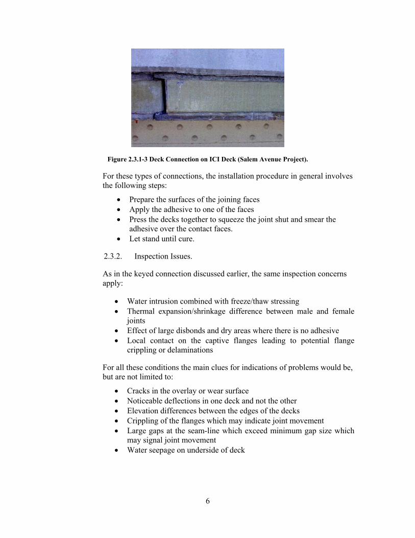
Infrastructure Composites, Inc. (ICI), also used a tongue and groove connection on their decks for the Salem Avenue Project in Dayton, OH (see Figure 2.3.1-3). It is assumed this would be typical for other projects as well.
Figure 2.3.1-1 Tongue and groove deck connection (MMC).
6
Figure 2.3.1-3 Deck Connection on ICI Deck (Salem Avenue Project).
For these types of connections, the installation procedure in general involves the following steps:
• Prepare the surfaces of the joining faces • Apply the adhesive to one of the faces • Press the decks together to squeeze the joint shut and smear the
adhesive over the contact faces. • Let stand until cure.
2.3.2. Inspection Issues.
As in the keyed connection discussed earlier, the same inspection concerns apply:
• Water intrusion combined with freeze/thaw stressing • Thermal expansion/shrinkage difference between male and female
joints • Effect of large disbonds and dry areas where there is no adhesive • Local contact on the captive flanges leading to potential flange
crippling or delaminations
For all these conditions the main clues for indications of problems would be, but are not limited to:
• Cracks in the overlay or wear surface • Noticeable deflections in one deck and not the other • Elevation differences between the edges of the decks • Crippling of the flanges which may indicate joint movement • Large gaps at the seam-line which exceed minimum gap size which
may signal joint movement • Water seepage on underside of deck

7
2.4. Butt Joints with Shear Splice Plate Strips
2.4.1. Description.
This method uses a butt joint between adjacent decks with splice plates field bonded to the top and bottom of the decks to transfer load as shown in Figure 2.4.1-1. This technique was used primarily by Hardcore Composites, Inc. (HCI), on the Salem Avenue Bridge Project. The installation involved the application of adhesive to the edge of the decks to be connected (see Figure 2.4.1-2) followed by the bonding of slice plate strips on the top and bottom of the decks (see Figure 2.4.1-3). To keep the splice strips in place while the adhesive cures, self-tapping screws were used. As far as this team is aware, HCI is the only manufacturer who has used this type of deck-to-deck connection versus some form of embedded captive feature as described in the previous two connection methods.
Figure 2.4.1-1 Detail of HCI Deck to Deck Joint (Salem Avenue Bridge).

8
Figure 2.4.1-2 Application of Adhesive on Splice Plates (Salem Avenue Project).
Figure 2.4.1-3 Mounting Splice Plates onto HCI Deck (Salem Avenue Project).
2.4.2. Inspection Issues.
The same inspection concerns apply as in the other connections with additional concerns stemming from the bonding sensitivity of the splice plate strips:
• Water intrusion combined with freeze/thaw stressing • Thermal expansion/shrinkage difference between the decks and
splice plates • Effect of large disbonds and dry areas where there is no adhesive • Improperly mounted splice plates

9
For all these conditions the main clues for indications of problems would be, but are not limited to:
• Cracks in the overlay or wear surface • Noticeable deflections in one deck and not the other • Elevation differences between the edges of the decks • Pop-off of the splice plates and consequent wear surface damage • Large gaps at the seam-line which exceed minimum gap size which
may signal joint movement • Water seepage on underside of deck
2.5. Comments on inspectability of deck-to-deck connections
The deck-to-deck connection is probably the most accessible part of the bridge deck and the most likely part of the deck system to develop problems because of improper installation, environmental swings, or excess loading. Experience with the Salem Avenue Bridge Project and ad hoc inspection/observation of bridge decks on the King Stormwater Canyon, Tech 21, and Darke County bridges have shown that the first instance of problems generally occurs at the deck connections in the form of overlay/wear surface cracking or spall.
3.0 DECK-TO GIRDER CONNECTIONS
3.1. Blind Connections. The deck-to-girder connection is critical to the continued operations of the bridge. However, this connection by nature is well hidden and is the most difficult part of the deck anatomy to directly inspect mainly because of the blind nature of the interface typically located within and below the traffic surface. The discussion of deck-to-girder connections will be limited to those methods that are being successfully applied to practice in existing decks. The most common type of connections in use currently are:
• Shear stud connections • Clip connects, and • Bolted connections
A description of these connections and discussions on inspections follow.
3.2. Shear Stud Connections.
3.2.1. Description.
This connection is adopted from the method used to anchor precast concrete slabs onto steel girders using Nelson shear studs welded onto the top of the steel girders through holes bored into the top and bottom facesheets of the composite deck as shown in Figure 3.2.1-1. In the hollow-celled core of MMC’s pultruded deck for instance, the open center lends itself to placing foam dams on the sides of the connection ports. One or more studs are used as required per connection pocket.

10
After the studs are shot, the cavity is then filled with grout to lock in the studs and deck. This setup is repeated down the length of the girder in a predetermined spacing based on design requirements.
To take up the irregularities between the girders and deck work, a haunch is typically built-up by flowing grout beneath the decks, into the cavity between the top of the girder and bottom of the deck as the preparation shows in Figure 3.2.1-2.
Figure 3.2.1-1 Typical Shear Connection on MMC Deck.
Figure 3.2.1-2 Deck Being Laid Down on Steel Girders (MMC)
Martin Marietta Composites uses this anchoring method on nearly all installations. This method was the standard for all the composite decks supplied by Hardcore, Creative Pultrusions, and Infrastructure Composites for the Salem Avenue Bridge Project.

11
3.3.2. Inspection Issues.
This is a difficult feature of the composite decks to inspect. All features of the connection are hidden from plain sight from above and below. Thus, the health of the connection can only be inferred by the observation of the overall behavior of the deck and any performance changes noted over a period of time. Suggestions for observation include:
• Behavior, i.e., movement of the deck under load. Check to see if it is bouncing more than in the past
• Observe any gaps between the haunch or girder and bottom face of the deck to see if there is noticeable vertical motion
• Observed rise and fall of the deck surface with temperature extremes which may indicate a failed stud connection.
• Tap test around suspect connections on the top and from the bottom to detect signs of separation in the facesheet
• Water seepage on underside of deck through the connection holes. This may not indicate stud failure, but may require corrosion prevention measures.
Any unusual localized motions vertically may indicate a weak or failed connection, so steps may have to be taken to diagnose the problem.
3.3. Clip Connections.
3.3.1. Description.
This type of connection has been used by Kansas Structural Composites (KSC) and Hardcore to anchor their decks in some installations. This connection basically anchors the deck to the girders by vertically clamping it to the girder flange with side clips. Examples of these types of connections are shown in Figures 3.3.1-1 and 3.3.1-2 for KSC’s Jane Street Bridge, MO. HCI has used similarly functioning clips in several deck installations, but the team was not able to discern which projects.

12
Figure 3.3.1-1 Anchor Clips Used on Jane Street Bridge (KSC).
Figure 3.3.1-2 Girder Clips for Jane Street Bridge (KSC).
3.3.2. Inspection Issues.
The external feature of this anchoring method makes it more accessible to visual inspection than the blind shear studs provided access to the underside of the decks is available. The inspection steps include:
• Observe any gaps between the haunch or girder and bottom face of the deck to see if there is noticeable vertical motion.
• Observe rise and fall of the deck surface with temperature extremes that may indicate a failed bolt connection.

13
• If clips look intact, but the deck surface still moves noticeably, tap test around suspect connections on the top to detect signs of separation in the facesheet.
• Check for water seepage on underside of deck through the connection holes. This may not indicate stud failure, but may require corrosion prevention measures.
Again, any unusual localized motions vertically may indicate a weak or failed connection, so steps such as those in Level IV inspection may have to be taken to diagnose the problem.
3.4. Bolted Connections.
3.4.1. Description.
This connection uses threaded Nelson studs to anchor the composite decks onto the steel girders. Like the shear stud, the threaded stud is resistance-welded to the girder through the predrilled holes in the deck, as seen in Figures 3.4.1-1 and 3.4.1-2. This was used on MMC’s Schuyler Heim Lift Bridge Project, Long Beach, CA. After the stud is secured, nuts and washers are torqued onto the bolts to lock-down the deck. The nuts are secured with thread-lock, sealed, and the top facesheet holes are covered with a cap and wear surface.
Figure 3.4.1-1 Carbon/Fiberglass Deck Being Installed in the Schuyler Heim Bridge (MMC).

14
Figure 3.4.1-2 Decks are Secured to Girders Through Bolted Connections.
3.4.2 Inspection Issues.
The same inspection issues covering the shear stud connections apply here as well.
• Behavior, i.e., movement of the deck under load. Check if it is bouncing more than in the past.
• Observe any gaps between the haunch or girder and bottom face of the deck to see if there is noticeable vertical motion.
• Observe rise and fall of the deck surface with temperature extremes which may indicate a failed stud connection.
• Tap test around suspect connections on the top and from the bottom to detect signs of separation in the facesheet.
• Check for water seepage on underside of deck through the connection holes. This may not indicate stud failure, but may require corrosion prevention measures.
Any unusual localized motions vertically may indicate a weak or failed connection, so steps may have to be taken to diagnose the problem.