“isnake multiplayer intelligent snake...
TRANSCRIPT

Project Report
on
“iSnake Multiplayer Intelligent Snake Game”http://isnake.sourceforge.net
Submitted to
Inter College Undergraduate Project Competition
KUCC Software Meet 2008
Mar. 7, 2008
by
Abhishek Dutta Jitendra Harlalka Suraj Sapkota
[email protected] [email protected] [email protected]
cell: 9841559669 cell: 9803395335 cell: 9841579381

Table of Contents
1 Acknowledgment..................................................................................................................................1 2 Abstract.................................................................................................................................................2 3 Objectives.............................................................................................................................................3 4 Programming Environment...................................................................................................................4 5 Methodology.........................................................................................................................................5
5.1 iSnake Client Application..............................................................................................................6 5.1.1 Client Encoder/Decoder.........................................................................................................6 5.1.2 Client Network Interface........................................................................................................6 5.1.3 Input Handler..........................................................................................................................6 5.1.4 Game Field Matrix.................................................................................................................7 5.1.5 Game Field Canvas.................................................................................................................7 5.1.6 User Interface Components....................................................................................................7 5.1.7 Game Controller.....................................................................................................................7
5.2 iSnake Game Server......................................................................................................................8 5.2.1 Server Encoder/Decoder.........................................................................................................8 5.2.2 Server Network Interface........................................................................................................8 5.2.3 Virtual Game Field.................................................................................................................9 5.2.4 Player Information Manager...................................................................................................9 5.2.5 Random Number Pool............................................................................................................9 5.2.6 Status Server...........................................................................................................................9 5.2.7 Server Core...........................................................................................................................10
5.3 Intelligent Autonomous Opponent Snakes..................................................................................10 5.4 iSnake Game Server Manager (GSM) @ SF.net.........................................................................13
6 Project Management...........................................................................................................................14 7 Documentation....................................................................................................................................16 8 Limitations..........................................................................................................................................16 9 Future Enhancements..........................................................................................................................17 10 Conclusion........................................................................................................................................17 11 References.........................................................................................................................................18 12 ANNEX – A: Blackmamba – path finding algorithm 13 ANNEX – B: Viper – path finding algorithm 14 ANNEX – C: Program Flow 15 ANNEX – D: Inter Snake Communication Protocol (ISCP)

1 Acknowledgment
We offer gratitude to project supervisor Asst. Prof. Jayaram Timsina (Deputy HOD, Dept. Of
Electronics & Computer Engineering, IOE Pulchowk Campus) for guiding us throughout the
project.
We would like to thank all those forum members at JavaGaming.org
[http://www.javagaming.org] and Sun Java Forum [http://forum.java.sun.com] who replied
to our endless queries without any complain.
We acknowledge the creators of Quantum Random Bit Generator Service [QRBG –
http://random.irb.hr], which provides our game server with high quality random numbers.
1

2 Abstract
This project aims to bring the fun and simplicity of snake game with some new features. It will
include computer controlled intelligent opponents whose aim will be to challenge the human
players. It will also have the multiplayer feature that will allow more than one players to play
the game over a network.
This project explores a new dimension in the traditional snake game to make it more
interesting and challenging. The simplicity of this game makes it an ideal candidate for a
minor project as we can focus on advanced topics like multiplayer functionality and
implementation of computer controlled intelligent opponents.
2

3 Objectives
This game aims to change the way people think of traditional snake game. It will offer the
experience of commercial multilayer games to the player retaining the simplicity of traditional
snake game.
The major objectives of this project are:
● Create a snake game that will have all the functionality of traditional snake games.
● Introduce multilayer functionality in the game that will allow several players to play a
game simultaneously. It should be able to give the experience of a real time multiplayer
game to the players.
● Introduce computer controlled intelligent opponent (unique feature of this game) to
make the game more challenging and interesting. The movement and action of these
intelligent opponents will be controlled by computer whose aim will be to eat the food
before human players capture it.
3

4 Programming Environment
We used several open source tools to develop this project:
● Netbeans 5.5 IDE
All the developers of iSnake team used Netbeans IDE for the development of this
project.
● Inkscape 0.45 and Gimp 2.2
These graphics development tools were extensively used for the development of User
Interface components. The illustrations presented in this report have also been prepared
using these open source tools.
● Gnuplot
The data obtained during profiling of two path finding algorithms viz. Blackmamba and
Viper was plotted using gnuplot.
● OpenOffice Writer 2.2
All the project documents and this report were prepared using OpenOffice Writer 2.2.
● Wireshark Network Traffic Analyzer 0.99.6
During the development of iSnake Game Server Manager (GSM) @ SF.net, Wireshark
tool was used to analyze the network traffic.
4

5 Methodology
iSnake is a multiplayer version of traditional snake game (popular among cell phone gamers)
with computer controlled intelligent opponents that challenges the human players.
The player who hosts the game server is called “local player”. The iSnake Client Application
and Game Server run in separate execution domains. The iSnake Client App. for local player
communicates with the game server through network layer, just like other remote players, as
shown in illustration 1.
The complete iSnake application is divided into four major components:
● iSnake Client Application
● iSnake Game Server
● Intelligent Autonomous Opponent Snakes
● iSnake Game Server Manager (GSM) @ SF.net
5
Illustration 1: iSnake block diagram

5.1 iSnake Client ApplicationiSnake client application refers to the application used to play snake game. A player joins
an already existing iSnake game server using this application.
The main components of iSnake Client application are:
5.1.1 Client Encoder/Decoder
This module performs the encoding and decoding of messages leaving/arriving the
client network interface module using the protocol standard described in ANNEX D: Inter
Snake Communication Protocol.
5.1.2 Client Network Interface
It provides an interface to the Game Controller module for communication with the
game server hosted at local/remote computer. It is responsible for triggering of
appropriate methods of Game Controller when message from Game Server is received.
5.1.3 Input Handler
It manages the task of sampling key strokes from local player and forwarding it to
Game Controller when requested. It maintains a queue of size 2 so that quick keystrokes
are not lost. It is active only when the game is in running mode.
6
Illustration 2: Block diagram of iSnake Client Application

5.1.4 Game Field Matrix
Game Controller maintains the complete state of the game using game field matrix.
It is a 2D array of size 58x58 (equal to the game field dimensions). Each game field object
has a unique identifier in the game field. Game Controller updates the cells of this matrix
in each cycle to register the changes that occur in the game.
5.1.5 Game Field Canvas
It represents the game field as seen by the player. Game Controller analyzes the
game field matrix in each cycle and updates the game field canvas to represent the state of
game in that game cycle. Double Buffering [using java.awt.Canvas.createBufferStrategy()]
has been implemented to avoid flickering of game field. Each block in the game field has
dimension 10x10 pixels.
The update of game field canvas occurs in the way similar to the refreshing
technique of a cathode ray monitor. The game field matrix and game field canvas are
updated in separate thread. The update of game field canvas starts by scanning each
column of the 1st row in the game field matrix, then 2nd row and so on upto the 58th row.
The game field is refreshed twice during each game cycle (two refresh cycle for game field
canvas for each game cycle). This is done make the movements in the game field
smoother.
5.1.6 User Interface Components
This module includes all the components, except game field, visible to the player.
The look and feel of default swing components have been overridden to give the feel of a
game to the players. MIT OCW's course1 “[6.831] User Interface Design and
Implementation” was very helpful during design of most of the user interface components
of this game.
5.1.7 Game Controller
It is the most important component of the iSnake client application. It coordinates
the working of all the other modules in the application and handles all the messages
1 See References [Website]
7

received from the game server. Game Controller maintains the game cycle when the game
is running. This game cycle is synchronized with the game cycle of the game server. All the
updates to game field matrix are done during this cycle time. After expiry of each game
cycle the game field is repainted to reflect the changes in the game field.
5.2 iSnake Game ServeriSnake game server handles the multiplayer feature of this game and allows multiple
iSnake client applications to play the game hosted by that particular game server.
The main components of iSnake Game Server are:
5.2.1 Server Encoder/Decoder
This module performs the encoding and decoding of messages leaving/arriving the
server network interface module using the protocol standard described in ANNEX D: Inter
Snake Communication Protocol.
5.2.2 Server Network Interface
It provides an interface to the Server Core module for communication with the
remote/local players of the game being hosted. It is responsible for triggering of
appropriate methods of Server Core when message from remote/local players is received.
8
Illustration 3: Block diagram of iSnake Game Server

5.2.3 Virtual Game Field
Game server maintains the state of the game using a 2D array of size 58x58 (similar
to that used by Game Controller – refer to 5.1.4).
It is maintained by the game server to check whether the food has been eaten and
whether any player has collide with the wall. It maintains the head coordinate (not the
coordinates for tails) of each player. The head coordinate of players is moved in each game
cycle and checked for the presence of wall/food in that coordinate position. Server Core
generates corresponding event (collide or food eaten) and all the active players are
informed about the event in the same cycle.
5.2.4 Player Information Manager
It manages the information about the players involved in the game. Player
information like name, location, score, snake's starting position, snake color, etc are
maintained. A new entry is added whenever a new player joins the game. Similarly, when
the player leaves the game, it is removed.
5.2.5 Random Number Pool
Game server maintains a buffer of random numbers obtained from Quantum
Random Bit Generator service [QRBG http://random.irb.hr ]. This gives the game server
access to true random number. These random data is used to generate the position of food
and the starting coordinate of each player's snake.
If the random number service is unreachable pseudo random numbers are
generated using java.util.Random class provided by Java.
5.2.6 Status Server
Status server maintains all the information required to reply the current status of
the game server. The service of status server is utilized by iSnake Game Server
Manager(iSnake GSM)2 hosted at http://isnake.sf.net. The response of status server is a
well formed XML document that is parsed by iSnake – GSM to display information about
the game server in the website.
2 Refer to “5.4 iSnake Game Server Manager (GSM) @ SF.net”
9

A typical response of Status Server is given below:
<?xml version=”1.0” encoding=”UTF8”?>
<iSnake>
<GameServerData>
<GameServerAddress>124.41.228.219</GameServerAddress>
<GameServerPort>9669</GameServerPort>
<NoOfPlayersOnline>5</GameServerLocation>
<GameServerStatus>Waiting</GameServerStatus>
</GameServerData>
</iSnake>
5.2.7 Server Core
It is the most important component of the iSnake Game Server. It coordinates the
working of all the other modules in the application and handles all the messages received
from the remote players.
When the game is in "Waiting" mode, Server Core provides the facility of chat
messaging to the game players. During this state new players can join the game.
When all the players have sent signal to start the game, the Server Core changes
state to “Running” mode. If a new player tries to join the game, it receives a “NAK”
response. In this mode, Server Core maintains a game cycle time during which it receives
the movement coordinates (in terms of deltaX and deltaY) from the players. If a player
does not send any packet during this cycle time, server considers the movement coordinate
sent in last cycle for the current game cycle. After expiry of cycle time, game server
broadcasts a packet containing movement coordinates of each player to all the players
active in the game. The game server also checks if any player has eaten the food or if any
players have collided to the wall in each cycle.
5.3 Intelligent Autonomous Opponent SnakesThese are computer controlled snakes, in the game, whose aim is to challenge the
human players. We have two implementations of path finding algorithms to create
intelligent autonomous opponent snakes. These algorithms return the shortest possible
10

path from given source (S) and target (T) coordinate pair considering the obstacles (if
any) present in the game field. The code name3 for these two implementations are:
● Blackmamba (refer to ANNEX A)
● Viper (refer to ANNEX B)
A detailed paper describing the algorithm used by these two implementation is
present in ANNEX A and ANNEX B. The module implementing these two path finding
algorithm easily fits into the existing design of iSnake Client Application as shown in
Illustration 4
To know which of the two implementations perform better, we profiled them using a
simple JUnit test and the results were plotted using gnuplot:
3 Named after two popular species of venomous snakes
11
Illustration 4: Module implementing two path finding algorithms replaces the Input Handler module of standard iSnake Client application.

Illustration 6: Length of path returned by the two path finding algorithms
Turn around time plot
The time elapsed between the instant of supplying the (source,target) coordinate
pair (S,T) to the algorithm and the instant when it returns a path for supplied (S,T) pair is
called turn around time. From the plot of illustration 5, it is clear that the turn around
time for Viper is always smaller as compared to Blackmamba.
Path Length plot
The length of path (computed by counting the number of game field coordinates in
the path) returned by the two path finding algorithms is depicted by the plot of
illustration 6. It is clear from the plot that Viper implementation results in smaller paths
(and hence efficient) as compared to Blackmamba implementation.
NOTE: The value of turn around time and path length for the coordinate pairs 5,7,8 have
negative values for Blackmamba. This suggests that the algorithm was not able to compute a
path for given (S,T) pair in given timeout period (250 ms for this test).
12
Illustration 5: Turn around time for two path finding algorithms

5.4 iSnake Game Server Manager (GSM) @ SF.netiSnake Game Server Manager (iSnake – GSM) hosted at http://isnake.sf.net is used to
manage all the information about iSnake game servers being hosted over the Internet.
The iSnake – GSM has been developed using PHP. Java Web Start technology has been
used to deploy iSnake application at our website which automatically downloads/installs
iSnake application and its library dependencies. This provides the gamers with the facility
of “one click launch” of the iSnake application. It also make the distribution of updates of
the iSnake application to the end users very convenient.
The iSnake application deployed at our website has been digitally signed by the
iSnake team to address the security issues related to launch of Internet applications.
13
Illustration 7: Block diagram of iSnake Game Server Manager at http://isnake.sf.net

6 Project Management
The first thing we did before starting the work on iSnake was to register a project at
Sourceforge4. Apart from hosting services, it provided us several code and project management
services.
Illustration 8 shows the svn commit statistics for the isnake code repository at sourceforge. We
collaborated on project documents (including prototype designs, project plan, TODO list, etc)
using WIKI (http://isnake.wiki.sourceforge.net).
JUnit tests were developed to independently test some of the modules before integration. The
integration of modules developed by the three developers was performed in three phases:
● Phase 1 Integration (Sep. 28, 2007) chat functionality of the game was tested
successfully
4 http://www.sourceforge.net
14
Illustration 8: Commit statistics for iSnake subversion repository at http://isnake.svn.sourceforge.net

● Phase 2 Integration (Oct. 06, 2007) successful testing of basic version of multiplayer
snake game
● Phase 3 Integration (Feb 17 26, 2008) – integration of all the modules for iSnake 0.1
Beta release.
7 Documentation
Documentation of every task being done in the project was a priority for all the team members.
Almost every portion of the source code contains full code documentation conforming to
Javadoc standards.
There exists two path finding algorithms that implements intelligent opponent in the game viz
Blackmamba and Viper. These two algorithms have been fully documented with illustrations5.
The protocol devised for communication between game server and clients has been
documented in ANNEXD.
8 Limitations
The limitations of present implementation of iSnake are:
● The present implementation of iSnake can only be played in LAN. Due to large latency
time and bandwidth limitation, it cannot be played over the Internet.
● Path finding algorithms (Blackmamba and Viper) implemented in this game have their
own computation limitations which has been describe in ANNEX A,B.
5 Refer to ANNEX – A,B
Illustration 9: Screen shot of a snippet of source code showing method comments conforming to javadoc standards.

● Full stress test of the application has not been done yet. Hence, the response of game
server in unpredictable situations cannot be handled properly.
● iSnake's Game Server Manager (iSnake – GSM) located at http://isnake.sf.net is still in
its early development phase. There are some unresolved security issues.
9 Future Enhancements
● Port iSnake to cell phone platform and One Laptop Per Child – OLPC (which uses Sugar
Desktop environment). The presence of several connectivity options(Bluetooth, WIFI,
GPRS, CDMA) in cell phones makes it a very attractive platform for a multiplayer game
like iSnake. Local WIFI network formed by kids using OLPC laptops can be used as a
platform for iSnake's deployment.
● As iSnake game server communicates with remote playing using a well defined and
very simple protocol (Refer to ANNEX D), iSnake clients programmed in other
programming platform like Flash, Python, etc can be developed.
10 Conclusion
We were successful in creating a multiplayer version of traditional snake game. The computer
controlled intelligent opponents have been successfully tested in the game is a unique feature
of iSnake.
We learned several project management techniques used by professionals to develop large
scale project. The experience of working in team and integration of modules developed
independently, with just requirement specifications, is a very important achievement for the
iSnake team.

11 References
Books
1. The Java Programming Language, by Ken Arnold, James Gosling, David Holmes
ADDISONWESLEY, 2000, ISBN 8178081482
2. Java Threads, Second Edition, by Scott Oaks, Henry Wong
O'REILLY, 1997, ISBN 8173660573
3. Core Java – Volume I/II, Seventh Edition, by Cay S. Horstmann, Gary Cornell
PEARSON EDUCATION, 2005, ISBN 8129709325
4. Introduction to Algorithms, Second Edition, by Thomas H. Cormen, Charles E.
Leiserson, Ronald L. Rivest, Clifford Stein
MIT PRESS, 2001, ISBN 8120321413
5. Head First Java, Second Edition, by Kathy Sierra, Bert Bates
O'REILLY, May 2003, ISBN 8173666024
Websites
1. Netbeans Community Docs
http://wiki.netbeans.org/wiki/view/CommunityDocs
2. The Inkscape Tutorials Blog
http://inkscapetutorials.wordpress.com/
3. Smashing Magazine – On line magazine for designers
http://www.smashingmagazine.com/
4. The Java Tutorials
http://java.sun.com/docs/books/tutorial/
5. Timing Framework
https://timingframework.dev.java.net/

6. JavaGaming.org's Forum
http://www.javagaming.org/forums/index.php
7. MIT Open Course Ware 6.831 User Interface Design and Implementation
http://ocw.mit.edu/OcwWeb/ElectricalEngineeringandComputerScience/6831Fall
2004/CourseHome/index.htm
8. Amit's A* Page – Tutorial on A* Path finding algorithms
http://theory.stanford.edu/~amitp/GameProgramming/
9. Arianne a multiplayer online games framework
http://arianne.sourceforge.net/
10.JavaDesktop Community Blog
http://community.java.net/javadesktop/
11.Java Forum
http://forum.java.sun.com
12.Blog of Romain Guy – coauthor of Filthy Rich Clients
http://www.curiouscreature.org/
13.Filthy Rich Clients Examples
http://www.filthyrichclients.com/
14.A Distributed Multiplayer Game Server System
http://warriors.eecs.umich.edu/games/papers/quakefinal.pdf
15.The Java Developers Almanac 1.4
http://www.exampledepot.com/
16.Apache MINA Sample programs and tutorials
http://mina.apache.org/
17.PHP Documentation for XML library
http://www.php.net/

18.Quantum Random Bit Generator Service (QRBG)
http://random.irb.hr/

ANNEX – A: Blackmamba – path finding algorithmProposed by: Abhishek Dutta
1 Some definitions and notations
1.1 Bounding Rectangle (br)It is a rectangle in which the source and the target lie at two opposite corners of the
rectangle. Source Bounding Rectangle (sbr0) and Target Bounding Rectangle (tbr0)
represent the bounding rectangles from source and target – which are the same
rectangle.
1.2 Partial Bounding Rectangle (pbr): These rectangles touch either the source or the target node and not both. Two
partial bounding rectangles touching 'S' and 'T' form paths from source to the
target node.
Source Partial Bounding Rectangle (spbr)
The pbr touching the source node 'S'.
Target Partial Bounding Rectangle (tpbr)
The pbr touching the target node 'T'.
Refer to Illustration 10
1.3 Notations:
1.3.1 brNM
denotes a bounding rectangle that spans ( or touches ) N nodes along the xaxis
and M nodes along the yaxis.
ANNEX – A A1
1.3.2 spbrNM
denotes a source partial bounding rectangle that spans ( or touches ) N nodes
along the xaxis and M nodes along the yaxis.
1.3.3 tpbrNM
denotes a target partial bounding rectangle that spans ( or touches ) N nodes
along the xaxis and M nodes along the yaxis.
1.3.4 hpNM
denotes a hopping point (coordinate specified with reference to source) along
which spbrNM and tpbrNM are formed. This coordinate point is common to
both spbrNM and tpbrNM
1.3.5 Numbering of Paths
For any given bounding rectangle (br) there are only two possible paths as show
in Illustration 11. Path numbering convention applied is:
Path1: The xcoordinate of the path first changes followed by change in y
coordinate
Path2: The ycoordinate of the path first changes followed by change in x
coordinate
A source (S) and target (T) can be placed in four possible ways such that they
lie on opposite ends of the diagonal. Considering the four position (A,B,C,D) as
depicted in Illustration 11, we have the following four cases:
1.3.5.1 'S' placed at position A and 'T' placed at position C
Path1 = ABC, Path2 = ADC
1.3.5.2 'S' placed at position B and 'T' placed at position D
Path1 = BAD, Path2 = BCD
1.3.5.3 'S' placed at position C and 'T' placed at position A
Path1 = CDA, Path2 = CBA
ANNEX – A A2

1.3.5.4 'S' placed at position D and 'T' placed at position B
Path1 = DCB, Path2 = DAB
2 Basis of this algorithm
In absence of any obstacles, the cost of moving from one node to another is constant
throughout the game field. Hence, the shortest path is along the bounding rectangle edges
if no obstacles are present in the path as shown in Illustration 11.
Both path1 and path2 have equal traveling cost provided that no obstacles are present
along those paths. For any given br, if there exists a path from source to target inside the
br then it will be the shortest path.
3 Paths generated by partial bounding rectangles
Four paths are generated by the source and target partial bounding rectangles for the
given hopping point as shown in Illustration 12.
ANNEX – A A3
Illustration 10: Bounding rectangle (br - dotted gray), Source bounding rectangle (spbr - dotted red) and Target bounding rectangle (tpbr - dotted green)
Illustration 11: Two possible paths along the edges of the bounding rectangle (dotted red line rectangle) provided no obstacles exists along the path

For any given (S,T) pair, we move the hopping point along the diagonal joining S and T.
Special considerations is required when:
● obstacles (wall) are present along the paths formed using the bounding and partial
bounding rectangles.
● No possible path can be found using all the possible combinations of the partial
bounding rectangles.
● the bounding rectangle is not a square ( ie: for brNM, N ≠ M )
4 Description of the algorithm
Instead of considering all the possible cases at once, let us consider the working of
algorithm in several stages (with increasing complications).
4.1 [A] Symmetric Bounding Rectangles (Simple Case)For illustration purpose, let us first consider a game field of 6x6 nodes where source
and target are placed at 'S' and 'T' respectively as shown in Figure A1. The following
series of steps are executed to find a path from source to target. If obstacle is found in
ANNEX – A A4
Illustration 12: Four possible paths generated by source and target partial bounding rectangles (spbr,tpbr - depicted using red and green dotted lines respectively) for a given hopping point

all possible path of an stage the next stage is checked. The series of steps taken to
obtain a path from 'S' to 'T' are:
4.1.1 Procedure of finding path for a given (S,T) pair
4.1.1.1 Figure A2 – initially the hopping point is hp66 (on the target). two paths
formed along the bounding rectangle br66 (shown in red dotted rectangle in
Figure A2) are checked for presence of obstacles. If no obstacles are found, either
path1 or path2 are chosen (refer to Illustration 11). As both path1 and path2
have same path length, choice between these two paths is made based on some
combination of sub paths and choosing the path whose length is shortest.
4.1.1.2 Figure A3 four paths (refer to Illustration 12) formed along the source and
target partial bounding rectangle (spbr55, tpbr22) are checked for presence of
obstacle.
4.1.1.3 Figure A4 four paths (refer to Illustration 12) formed along the source and
target partial bounding rectangle (tpsbr44, ptbr33) are checked for presence of
obstacle.
4.1.1.4 Figure A5 four paths (refer to Illustration 12) formed along the source and
target partial bounding rectangle (tpsbr33, ptbr44) are checked for presence of
obstacle.
4.1.1.5 Figure A6 four paths (refer to Illustration 12) formed along the source and
target partial bounding rectangle (tpsbr22, ptbr55) are checked for presence of
obstacle.
4.1.1.6 Figure A7 This step is not necessary to execute as the task has already
been performed in Step 1 using the bounding rectangle (br66).
See Illustration 13 for illustration of steps 1 to 6
Computation overhead calculations
Let the time required to check whether a partial bounding rectangle has an obstacle
ANNEX – A A5

= T1
time required to check whether a bounding rectangle has an obstacle = T2
for a game field NxN (row x col)
also let (to create the worst case)
the source 'S' be located at (1,1)
the target 'T' be located at (N,N)
Total no. of possible hopping points (excluding the source) = N – 1
Hence, total time required to calculate a path6 = T2 + N * T1
6 See section “Requirements of this algorithm”
ANNEX – A A6

ANNEX – A A7
Illustration 13: Illustrations for “[A] Symmetric Bounding Rectangles (Simple Case)”

4.1.2 Backtracking
If 4.1.1.1 to 4.1.1.6 does not give a path from 'S' to 'T' the technique of backtracking
will be applied. To illustrate the process of backtracking let us consider the scenario
shown in Illustration 14.
The paths generated from the bounding rectangle (br44) and all the possible partial
bounding rectangles contain obstacle. Hence the process discussed above will not
result in any path from 'S0' to 'T'. For such scenario we can apply the process of
backtracking.
ANNEX – A A8
Illustration 14: Game field scenario when all the paths formed by bounding and partial bounding rectangles contain obstacle.

Backtracking involves moving to the next outer (as inner bounding rectangles do not
contain any path for sure) bounding rectangle a path to the target is found.
Illustration 15 shows the result of backtracking. Backtracking from S0 to S1 (the
next outer bounding rectangle) results in a bounding rectangle br55. This bounding
rectangle does not also result in any path from S1 to T. Hence, next outer bounding
rectangle is checked.
The next outer bounding rectangle (br66) is formed at node S1 as shown in
ANNEX – A A9
Illustration 15: Next outer bounding rectangle (br55) is checked for a path from node S1 to T.
Illustration 16: Next outer bounding rectangle (br66) is checked for a path from node S2 to T.

Illustration 16. This bounding rectangle has a path from S2 to T. Hence, the possible
path is calculated to reach from S2 to T.
As we now have a path from S2 to T, we need to calculate a path from S0 to S2 so
that we can ultimately reach T from S0. Now we calculate the possible path from S0
to S2 using the steps discussed above as shown in Illustration 17.
By joining the paths formed from the above two steps can be combined to form a
path from S0 to T.
4.1.2.1 Determining next outer bounding rectangle during backtracking
Although the vertex for next outer bounding rectangle (required for
backtracking) can be the next coordinate on the extended diagonal (as shown in
Illustration 15,16), a simple technique can greatly reduce the number of
backtracking steps of both source and target.
Let source (S) and target (T) be placed as shown in Illustration 18. A path from
S to T contains two edges. Path1 contains edge1 and edge2. Path2 contains
edge4 and edge3. While determining whether a path contains obstacle, the
algorithm must also determine which edges contains obstacles (if any).
ANNEX – A A10
Illustration 17: Path from node S0 to S2 is calculated using the process discussed before (after a path is found from S2 to T
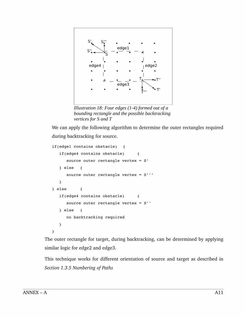
We can apply the following algorithm to determine the outer rectangles required
during backtracking for source.
if(edge1 contains obstacle) {
if(edge4 contains obstacle) {
source outer rectangle vertex = S'
} else {
source outer rectangle vertex = S'''
}
} else {
if(edge4 contains obstacle) {
source outer rectangle vertex = S''
} else {
no backtracking required
}
}
The outer rectangle for target, during backtracking, can be determined by applying
similar logic for edge2 and edge3.
This technique works for different orientation of source and target as described in
Section 1.3.5 Numbering of Paths
ANNEX – A A11
Illustration 18: Four edges (1-4) formed out of a bounding rectangle and the possible backtracking vertices for S and T

4.1.2.2 Merging the paths formed while backtracking
While backtracking several sub paths are created while requires to be merged to
form the final path from source to target. Let us consider a case as depicted in
Illustration 19.
Due to the presence of wall (green blocks), S and T has to backtrack to S' and T'
positions respectively. Here we obtain three sub paths which are:
Path from S to S' : depicted by red colored line from S to S' (SubPath1)
Path from S' to T : depicted by blue colored line from T to T' (SubPath2)
Path from T' to T : depicted by pink colored line from T' to T (SubPath3)
We need to combine these three paths to obtain a final path from S to T
(depicted by thick black line). If we add these three paths directly, the final path
will contain overlapping paths (which is not required). The following algorithm
can be applied to compute the final path (that does not contain any overlapping
regions).
START
Step 1: Initialize FinalPath with the contents of SubPath1
ANNEX – A A12
Illustration 19: Sub paths formed during backtracking. Final path from S to T obtained by combining the sub paths.
FinalPath = SubPath1
Step 2: Now perform the following operations for each cell coordinate
present in SubPath2 and SubPath2 (K=2,3)
cellCoordinate = SubPathK.getCellCoordinate()
if(FinalPath contains cellCoordinate) {
remove cellCoordinate from FinalPath
} else {
add cellCoordinate to FinalPath
}
Step 3: FinalPath contains discontinuities at the bends of path. Search for
consecutive cell coordinate for which both x and y values of the coordinate
change (ie: |dx| = 1, |dy| = 1).
Step 4: Correct these discontinuities by adding the missing cell coordinates.
END
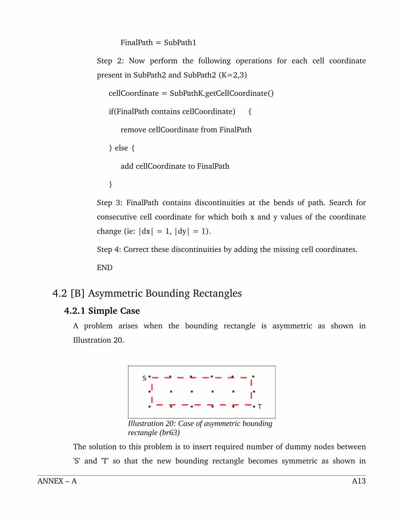
4.2 [B] Asymmetric Bounding Rectangles
4.2.1 Simple Case
A problem arises when the bounding rectangle is asymmetric as shown in
Illustration 20.
The solution to this problem is to insert required number of dummy nodes between
'S' and 'T' so that the new bounding rectangle becomes symmetric as shown in
ANNEX – A A13
Illustration 20: Case of asymmetric bounding rectangle (br63)

Illustration 21. The algorithm applied in “[A] Symmetric Bounding Rectangles
(Simple Case)” can be now applied by considering the dummy nodes as normal
game field nodes free from any obstacles.
4.2.2 S and T lying on same straight line (vertical or horizontal)
This case arises when both 'S' and 'T' lie on same straight line (horizontal or
vertical) as shown in Illustration 22.
The case can be converted to “[A] Symmetric Bounding Rectangle (Simple
Case)” case by adding dummy nodes as shown in Illustration 23.
ANNEX – A A14
Illustration 21: The bounding rectangle (br66) is made symmetric by adding required no. of dummy nodes
Illustration 22: Another case of asymmetric bounding rectangle (br61)

5 Requirements
5.1 Constant time algorithm for obstacle detectionThere must exist a constant time algorithm that can answer the question “Does the
given bounding or partial bounding rectangle contain any obstacle?”. The
constant time algorithm requirement means that the YES/NO decision of this
algorithm should not depend on the size of rectangle under consideration or the
number of obstacles present in the game field.
An important observation for iSnake game is that the obstacles in the game are not
dynamic. In other words, the obstacles remain constant until a given FOOD is eaten
by one of the players. Hence we can assume that the obstacle is constant during the
execution of this path finding algorithm.
We apply the following algorithm to detect whether a given bounding rectangle
contains any obstacles.
START
ANNEX – A A15
Illustration 23: The case can be converted to “[A] Symmetric Bounding Rectangle (Simple Case)” case by adding dummy nodes

Step 1: Let (x1,y1) = one corner of the bounding rectangle
(x2,y2) = diagonally opposite corner of the bounding rectangle
obstacle = a set coordinates defining the obstacle (wall)
Step 2: Repeat step 2 for each cell coordinate in obstacle
oc = obstacle.getCellCoordinate()
path1HasObstacle = true, path2HasObstacle = true
if( x >= x1 and x <= x2 ) {
if(!path1HasObstacle) {
if( x1y1.ggggetY().equals(y) )
path1HasObstacle = true
}
if(!path2HasObstacle) {
if( x2y2.gggetY().equals(y) )
path2HasObstacle = true
}
}
if ( y >= y1 and y <= y2 ) {
if(!path1HasObstacle) {
if( x2y2.getX().equals(x) )
path1HasObstacle = true
}
if(!path2HasObstacle) {
if( x1y1.getX().equals(x) )
path2HasObstacle = true
}
}
Step 3: if(path1HasObstacle) {
if(path2HasObstacle)
return NO PATH POSSIBLE
else
return PATH2 is OBSTACLE FREE
} else {
ANNEX – A A16

if(path2HasObstacle)
return PATH1 is OBSTACLE FREE
else
return PATH1 and PATH2 are OBSTACLE FREE
}
END
6 Limitations
6.1 This algorithm does not consider the transparent game field boundary (entry to one
side of the field causes exit in the opposite side of the field as depicted in Illustration
24) during path calculation. Due to this limitation the computed path is not optimal.
6.2 The hopping points are always taken from the diagonal line joining the source and
target. Because of property of the algorithm, it is not able to compute paths when a
complex structure of wall, as shown in Illustration 25, is present. This is the reason why
Blackmamba implementation enters infinite recursion for such obstacles.
ANNEX – A A17
Illustration 24: Transparent boundary of the game field

ANNEX – A A18
Illustration 25: Only 1 hopping point prevents this algorithm from computing path in presence of a complex structured wall

ANNEX – B: Viper – path finding algorithmProposed by: Suraj Sapkota
1 Assumptions
This algorithm assumes game field as follows:
● The rectangle with the dotted boarder is the view port(vp) of each player. Other
rectangles attached with it in each side are the virtual view port(vvp) in their
corresponding sides.
● Small yellow box is a wallunit. Group of attached wallunit is said to be wall.
● The border of the gamefield are transparent unless there is wall.
● Wall is the only thing that a snake can strike to.
● There can be multiple wall in the same gamefield.
ANNEX – B B1
Illustration 1: The game field (unfolded Envelop)

● Finally considering all these, the aim of this algorithm is to find all (there may be
multiple path of same distance) shortest path from the snake (head) to food. However
as a result it will return only one among those paths.
2 Principal and implementation of this algorithm.
This algorithm will not deal with finding only one shortest path instead it calculates multiple
path between the source and the destination, and all of these path have the same distance, the
shortest distance. Actually the result is not in the form of multiple path, merely it is a
collection of the points that it must pass through. It is the position of the points that make
the path multiple. It is described later in more detail.
The algorithm follows following steps:
1. This algorithm begins with splitting all the game field into small rectangles (Fundamental
open rectangle7 (FOR8)), say R1, R2, R3, ... Rn. If gamefield (only view port), as a whole is
said to be G. Then mathematically the wall, W can be defined as:
W = G R1 U R2 U R3 U ... U Rn
Broadly, this algorithm deals with splitting the game field into several (as many) rectangles
such that, the union of all these small rectangles result in the game field that exclude wall. ie,
the snake can move safely from any point in the rectangle(Ri) to any other point within the
same rectangle(Ri)and hence called Open rectangles (OR).
7 Open rectangle is a rectangle that does not contain any wall. Within it snake can move freely.8 The algorithm of generating FOR is discussed later.
ANNEX – B B2

2. Next we define Gate9 (Gate as in real life is a way to move from a FOR to another adjacent
FOR) calculate the shortest distance between each two Gates of each FOR (eg: the shortest
distance between the rectangles R1 and R5 are determined by the distance between the two
gates of R3 shared with R1 and R5 respectively).
3. After the calculation of the shortest path, a graph as shown in Illustration 4 is formed.
In the above graph
i. The dotted lines defines direct connection, the direct path.
ii. The dark line shows a 1 step indirect connection between those rectangles that are not
connected directly.
9 A gate must be common to only two FOR.
ANNEX – B B3
Illustration 4: Graph
Illustration 3: "Illustration 2" in broader view
Illustration 2: Slitted into 6 small pieces of rectangle.

iii. Sij, beside with the vertex, (in graph) denotes that FORi is connected to FORj through
this vertex and vice versa. This can also be called indirect path. And it posses the path
distance.
iv. There may be multiple indirect path. Eg: We can move form 2 to 5 (S25) in two
different ways: via 3 or 5.
Some data that are associated with the rectangle (node in the graph) is shown below.
4. Finally after all these calculation, we can calculate the path between two FOR's, the source
and the destination with shortest distance. When two points (source and target) are given we
can determine the FOR's, they lie in and can compute the path between them.
ANNEX – B B4
Illustration 5: Data associated with each node
Illustration 7: Zoomed view of "Illustration 6"Illustration 6: Path for a sample case.

The above sample case shown in illustration 6 and 7, shows the path calculated by the
algorithm from the snake (red one pointed by an arrow A) to the food (blue one pointed by an
arrow F). The points pointed by the arrows A, B, C, D, E and F are points (Hoping Points) that
the intelligent player must pass through. And thus allowing multiple possibility for path.
The path is multiple because, there exist multiple way to go from A to B and E to F. Further
the rectangles as formed by the points A and B ( E and F ) can also be called Derived open
rectangle (as it doesn't contain any wall, and hence allows free movement of the snake inside
it).
3 For dividing the Game field into fundamental open rectangle:
The algorithm involves slicing the gamefield in cyclicorder
in anticlockwise direction starting with the left edge. As the
game field initially has no terminating edge (as envelope) we
start with (visually) leftedge of the game field.
1. Initially starting from the Zeroth coordinate move to
both sides until it strike to wall(unit).Name it Fundamental Open Rectangle (FOR1 and
FOR2 or Just R1 and R2). Illustration8 and 9.
2. Now the gamefield has shrinked to as shown in
Illustration10. (It now has changed to cylindrical
shape from envelope shape.)
3. Moving in anticlockwise direction, Slice from
bottom in both direction (up and down) to get other two rectangle R3 and R4.
Illustration11.
ANNEX – B B5
Illustration 8: Step 1 (a)
Illustration 9: Step 1 (b)

Till this step the rectangle was not bounded (either in
all four sides (envelop) or in two sides(top and bottom)
(cylinder)). From this step onwardthe sliced game
field would be bounded.
4. Now try to slice rectangle from top left, bottom
left,bottom right and topright respectively. Here we fail
to slice the rectangle from topleft and bottomright as
there is wall(unit) at the edge.
We can now create two new rectangles from bottomleft
and topright namely R5 and R6. Illustration13.
5. Now slice away the boundary layer of the gamefield
formed in Illustration13.Shown in Illustration14.
6. As earlier again try to slice the gamefield in the anticlockwise direction starting from
left. It will result in two more rectangle R7 and R8. Illustration15.
During this we assume already sliced rectangle as a
hollow space.
7. For Further Optimization we proceed by breaking down the rectangle that touches
itself (eg: in this case, the top edged of rectangle R1 touch itself to its bottom edge). These
type of rectangles are divided in the middle. This results in best utilization of the transparency
of the Game Field.
ANNEX – B B6
Illustration 10: Step-2
Illustration 12 Illustration 13: Step 3
Illustration 14: Step 4Illustration 15
Illustration 11: Step-3

4 Special case for Game Field with no wall
If there is no wall we simply chop the game field vertically and horizontally from the middle
resulting in 4 FOR's. This results in maximum utilization of the transparency of the game
field. The result is shown in Illustration 17.
ANNEX – B B7
Illustration 16: The Final Result
Illustration 17: Sliced Game Field with no wall

5 Salient Features:
● As most of the processing is done before the actual game starts, it must reduce the the processing time during the game-time.
● The concept of open-rectangle allows multiple path, and hence within it the snake can be moved randomly towards the specified point. And hence it is intelligent.
● Furthermore, during the calculation of the path the snake can move within the FOR in which it currently lie.
6 Limitations:
● If the number of FOR increases to too high, then it will obviously be tough and slow to determine the shortest path.
ANNEX – B B8

ANNEX – C: Program flow
NOTE: "EXT" refers to the actions that are triggered by Client Network Interface module when
messages are received from game server
ANNEX – C C1
Illustration 26: iSnake game application enters in STAGE-1 and exits through STAGE-5
Illustration 27: iSnake game application starts in STAGE-1 and this stage involves connection to game server specified by the player

NOTE: "EXT" refers to the actions that are triggered by Client Network Interface module when
messages are received from game server
ANNEX – C C2
Illustration 28: In STAGE-2 players can chat with each other. The game will start only when all the players connected to the game server send READY signal

NOTE: "EXT" refers to the actions that are triggered by Client Network Interface module when
messages are received from game server
ANNEX – C C3
Illustration 29: STAGE-3 involves receiving different game data (like wall coordinates, food coordinate, snakes start position, etc)

NOTE: "EXT" refers to the actions that are triggered by Client Network Interface module when
messages are received from game server
ANNEX – C C4
Illustration 30: STAGE-4 involves synchronization with the game server

NOTE: "EXT" refers to the actions that are triggered by Client Network Interface module when
messages are received from game server
ANNEX – C C5
Illustration 31: STAGE-5 represents the state when game is being played

ANNEX – D: Inter Snake Communication Protocol
The communication between the game server and client applications is done using the Inter
Snake Communication Protocol (ISCP). The protocol contains five different classes. These are
listed below:
Information Used for transmission of player's information (name, color,
location). Used only when the player creates/joins the
game.
ChatMessage Transmits the chat message. Works only before the actual
game starts.
ControlSignal Transmits control signals between server and clients. These
signals are mainly used for synchronization.
LevelData Sends data required on level change (food, wall, score, life,
etc). Sent initially when the actual game begins and then
after every level change.
Move Transmits the movement of clients, collision information
and also the information about food capture.
The communication packets are encoded in byte format for the purpose of transmission and
are decoded in similar fashion. The encoding and decoding of packets in client side is handled
by ClientEncoder and ClientDecoder respectively. Similar for game server, encoding and
decoding is handled by ServerEncoder and ServerDecoder respectively.
For instance, the server encoder for chat message is known as ChatServerEncoder. The
encoders and decoders are placed under net.sf.isnake.codec.
On the basis of communication packet flow, we can classify the communication basically into
two types:
● Client Initiated Communication: In this type of communication, the client first
ANNEX – D D1

encodes the packet with necessary data. Send it to server in flipped order. Flipping is
required so that it gets received in correct order at the other end. The server decodes it.
The server reencodes the data with some further informations (if required such as
sender's Id) and flips it. This packet is retransmitted to clients where it is decoded. The
communication cycle is shown below:
● Server Initiated Communication: In this type of communication, server first encodes
the packet with necessary data and transmits in flipped order. The packet is decoded on
client side. The communication cycle is shown below:
The five classes of communication can send various messages. All the messages are decoded
the same way they are encoded. Following conventions are used in depicting the encoding
over here:
Symbol Meaning
< > Shows fields to be sent along with identifier
( ) Shows the data type of the field. However, all the fields are converted into byte while encoding and on decoding they are received as bytes and converted to proper data type.
id Represents the player id (an integer used to uniquely identify a player in the game).
[ ] The fields within [] are part of an array in the protocol class.
Class: Chat Message
1 Packet Chat Text
Identifier CH
Type Client Initiated
Description Is used to transmit a chat message typed by a client to other clients.
to_id is required for one to one communication which is not currently
ANNEX – D D2
Client Encoder Client Decoder Server Encoder Server Decoder
Client Decoder Server Encoder

allowed in the game but has been designed for future enhancements. 0
is being sent as to_id which is basically a multi cast id.
ClientEncoder CH<to_id(byte)><len_of_message(short)><message(string)>
ServerEncoder CH<from_id(byte)><to_id(byte)><len_of_message(short)><messag
e(string)>
Class: Information
1 Packet Player info
Identifier IN
Type Client Initiated
Description Is used to transport the informations of a player viz; name, color and
location.
ClientEncoder IN<info_len(short)><name:color:location(string)>
ServerEncoder IN<info_len(short)><id:name:color:location(string)>
Class: ControlSignal
1 Packet Acknowledgment
Identifier AK
Type Client Initiated
Description This packet is sent when a client successfully receives Level data. The
status_code field has been reserved for future enhancements. As of
now it is sent as 0.
ClientEncoder AK
ServerEncoder AK<id(byte)><status_code(byte)>
2 Packet Quit
Identifier QT
ANNEX – D D3

Type Client Initiated
Description Sent when a client quits the game.
ClientEncoder QT
ServerEncoder QT<id(byte)>
3 Packet Ready
Identifier RY
Type Client Initiated
Description Is sent when the user specifies his readiness to start the game.
ClientEncoder RY
ServerEncoder RY<id(byte)><status_code(byte)>
4 Packet ID
Identifier ID
Type Server Initiated
Description This packet is sent by server to client to assign an id to the player. This
is done as soon as the client sends his information.
ServerEncoder ID<id(byte)>
5 Packet Start
Identifier ST
Type Server Initiated
Description Represents start of various events in the game on the basis of
status_code.status_code 0 represents the beginning of
transmission of level data. status_code 1 represents the beginning of
ANNEX – D D4

level synchronization task before beginning of a level and status_code 2
is a signal to start the actual level play.
ServerEncoder ST<status_code(byte)>
6 Packet Stop
Identifier SP
Type Server Initiated
Description Represents the end of level.
ServerEncoder SP<status_code(byte)>
7 Packet Force
Identifier FR
Type Server Initiated
Description This communication packet forces a player to send a ready packet when
all others have expressed their willingness to begin the game.
ServerEncoder FR<id(byte)><status_code(byte)>
8 Packet No Acknowledgment
Identifier NK
Type Server Initiated
Description This packet is sent by server when the information supplied by client is
not valid. status_code here represents field which has invalid data.
Invalid data occurs when information field contains reserved characters
or duplicate entry.
ServerEncoder NK<id(byte)><status_code(byte)>
ANNEX – D D5

Class: LevelData
1 Packet Begin from
Identifier BF
Type Server Initiated
Description The packet sends starting coordinate of all the players in a single
packet. The player begins level from this coordinate and is reset to this
coordinate on collision.
ServerEncoder BF<3*no_of_players(byte)>[<id(byte)><x_coordinate(byte)><y_co
ordinate(byte)>]
2 Packet Score
Identifier SC
Type Server Initiated
Description Sends score of all the players in the packet on beginning of a level.
ServerEncoder SC<8*2*no_of_players(byte)>[<id(long)><score(long)>]
3 Packet Level
Identifier LV
Type Server Initiated
Description Sends the level number to the clients.
ServerEncoder LV<level_number(byte)>
4 Packet Life
Identifier LF
Type Server Initiated
ANNEX – D D6

Description Sends the life count for each player on beginning of a level.
ServerEncoder LF<2*no_of_players(byte)>[<id(byte)><life_count(byte)>]
5 Packet Wall
Identifier WL
Type Server Initiated
Description Sends the wall coordinates to the clients.
ServerEncoder WL<2*wall_length(short)>[<x_coordinate(byte)><y_coordinate(byte
)>]
6 Packet Food
Identifier FD
Type Server Initiated
Description Sends the food coordinates to the clients on the beginning of a level.
ServerEncoder FD[<x_coordinate(byte)><y_coordinate(byte)>]
Class: Move
1 Packet Collide
Identifier CL
Type Client Initiated
Description The packet is sent when a player looses a life. Possibility of more than
one players colliding on same turn has been taken into account. At
present, however, we are checking the collision on server and the
communication is thus Server Initiated.
ANNEX – D D7

ClientEncoder CL
ServerEncoder CL<no_of_players_collided(byte)>[<collided_player_id(byte)>]
2 Packet Move
Identifier MV
Type Client Initiated
Description Carries the change in x and y (dxdy) of the clients to the server. Server
merges change in coordinate of all the clients in a new MV packet and
transmits to the clients.
ClientEncoder MV[<id(byte)><dx(byte)><dy(byte)>]
ServerEncoder MV<3*no_of_players(byte)>[<id(byte)><dx(byte)><dy(byte)>]
3 Packet Eaten
Identifier ET
Type Server Initiated
Description Server sends the packet whenever the food gets eaten. This packet also
initiates the generation of Food packet as a level can have more than
one food.
ClientEncoder ET
ServerEncoder ET<eaten_id(byte)>
FD[<x_coordinate(byte)><y_coordinate(byte)>]
ANNEX – D D8