antennas and cables - internet...
TRANSCRIPT

Antennas and Cables
Sebastian Büttrich, wire.less.dk
edit: September 2009, Pokhara, Nepal
Shortened version of
http://www.itrainonline.org/itrainonline/mmtk/wireless_en/08_Antennas_Cables/08_en_mmtk_wireless_antennas-cables_slides.odp
(edited by Alberto Escudero Pascal)
http://creativecommons.org/licenses/by-nc-sa/3.0/

Goals
• Focus on explaining the factors in the link budget equation
• Introduce a set of types of antennas and cables
• How to make the right choices– Optimal Service Area– Minimizing Interference– Best use of the radio spectrum
Table of Contents
• Review of Link Budget• Introduction to Antennas• Types of Antennas• Polarization• Cables and Connectors

Review of Link Budget
• A radio link has active and passive elements
• Antennas and Cables are passive elements
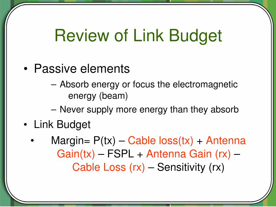
Review of Link Budget
• Passive elements– Absorb energy or focus the electromagnetic
energy (beam)– Never supply more energy than they absorb
• Link Budget• Margin= P(tx) – Cable loss(tx) + Antenna
Gain(tx) – FSPL + Antenna Gain (rx) – Cable Loss (rx) – Sensitivity (rx)
Antenna Definition
• A passive device used to transform an RF signal
• Transformation from signal in cable to signal in free space – and back
Antenna Gain• Antennas are passive elements that do not
amplify the radio power• Antennas target the signal in certain direction,
but make it weaker in others (!)• The antenna gain is a positive value to the
link budget

Antenna Gain• Compares the power sent by the antenna in a
certain direction with the “Isotropic Antenna”.
• Given in isotropic decibels [dBi]• Isotropic antenna
– a hypothetical antenna that radiates or receives equally in all directions
– a theoretical reference used as a way to express directional properties of physical antennas.

Radiation Pattern
• A graphical representation of the “shape” of the radio beam.
• Beam width: The area where 90% of the energy is focused.

Radiation Pattern
Source: http://www.its.bldrdoc.gov/projects/devglossary/images/beamwi4c.gif

Radiation Pattern
• Normalized dB scale– 0 dB: Direction of maximum gain of
the antenna.– 3 dB: Angle where the antenna
performs 50%. – The 3 dB beam width is normally
known as service area/volume

Radiation Pattern: Example
● Typical Radiation Pattern of Sector Antenna ● 3 dB VBeamwidth is 20º vertical and 90º horizontal

Omnidirectional Antenna
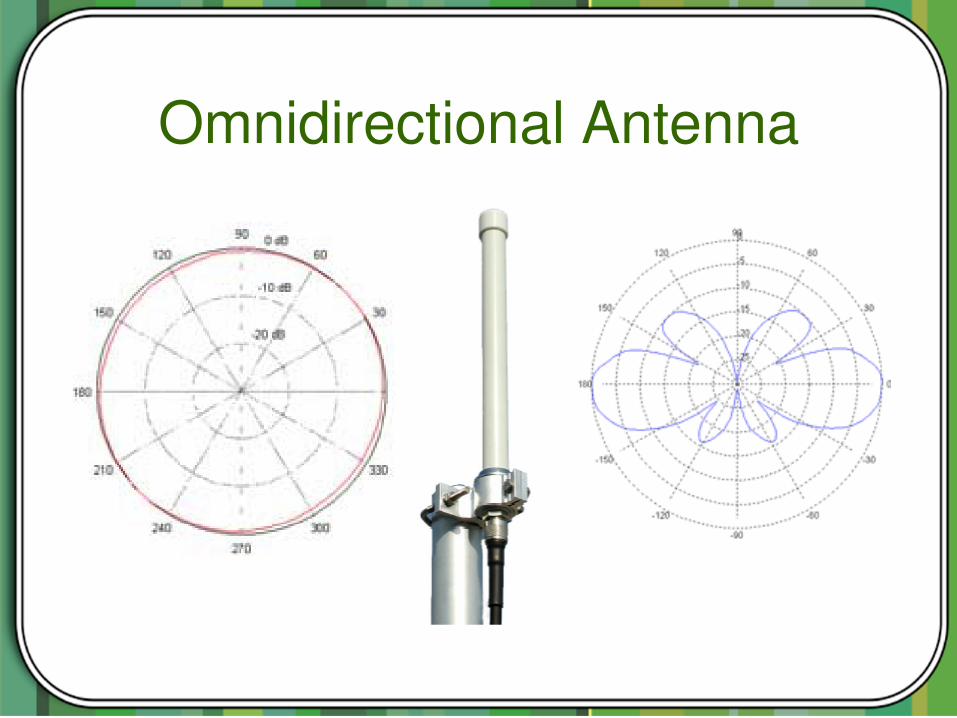
• 360degree RF radiation pattern. ••••• Normally vertically polarized Efield.• Normally low gain around 3 7 dBi.
Omnidirectional Antenna
• Best suitable for a wide service area with short links
• Be very careful when using Omni antennas
– Consider potential problems with hidden nodes
– Consider potential problems with interference
– Consider narrow vertical pattern!!!
Omnidirectional Antenna

Omnidirectional Antenna
• If trying to maximize the service “area”, you might have problems with nodes very close to the antenna

Sectoral Antenna
• Used in Access Points (gateways/hubs) to serve PointtoMultiPoint (PtMP) links.
• Normally vertically polarized but horizontally polarized are also available
• Typical gain of 613 dBi

Sectoral Antenna• Good for serving a large area with a high
density of connections• Horizontal beamwidth to about 30120º
Azimuth (Hfield) radiation
pattern Elevation (Efield) radiation
pattern

Sectoral Antenna
• A sectorial antenna with high gain needs careful mounting with respect to downtilting

Sectoral Antenna
• Why do we need to sectorize?– Allows for multiple access points in one
tower. More total bandwidth.– Able to isolate areas with higher levels
of RF noise– Be able to separate short from long
distance links (stability)

Directive Antenna
• Parabolic Antenna• High Gain Patch / Panel Antennas• Wave Guide Antenna (Circular: The
famous Cantenna)• Biquads

Parabolic Antenna• Grid or closed surface• Horizontally or Vertically
Polarized
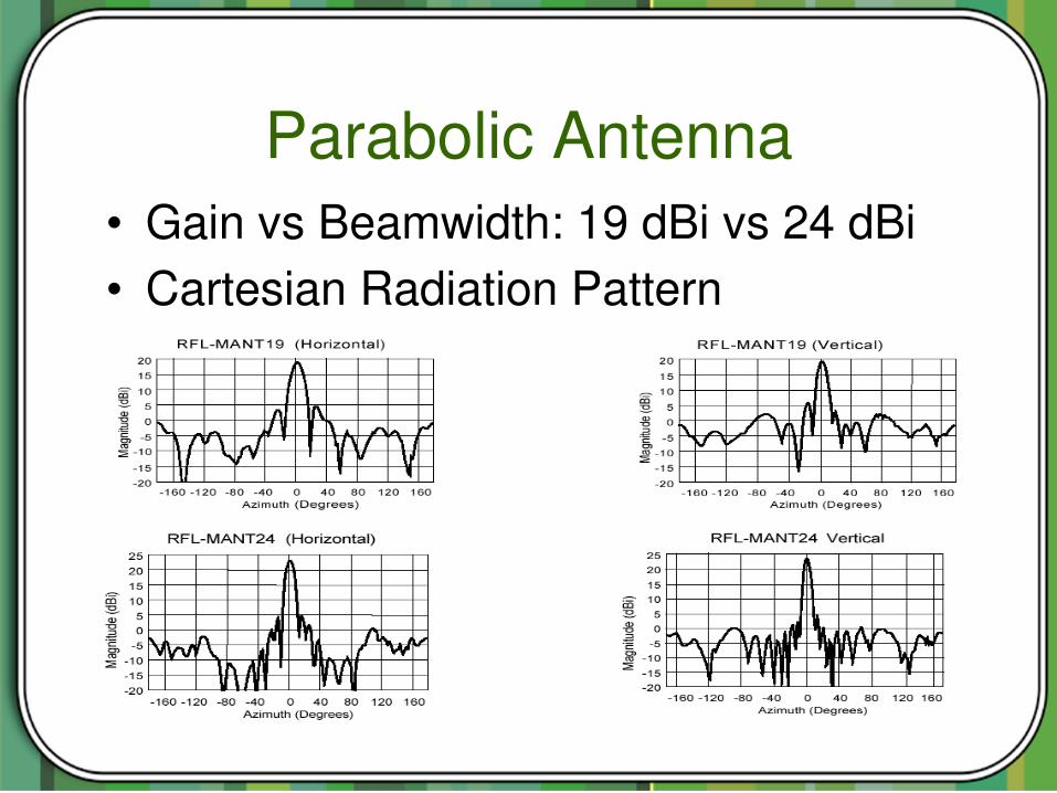
Parabolic Antenna• Gain vs Beamwidth: 19 dBi vs 24 dBi• Cartesian Radiation Pattern
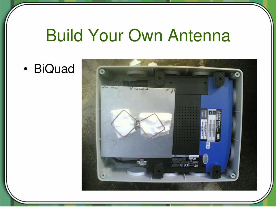
Build Your Own Antenna
• Good quality and low cost antennas can be made mostly using common household goods
• Most suited: Cantennas, Biquads, Omnis (more difficult)
• Guides can be found many places on the net, e.g. at http://wirelessU.org and http://wireless.ictp.it/handbook/download.html

Build Your Own Antenna
• Cantenna

Build Your Own Antenna
• BiQuad
Build Your Own Antenna
• BiQuad
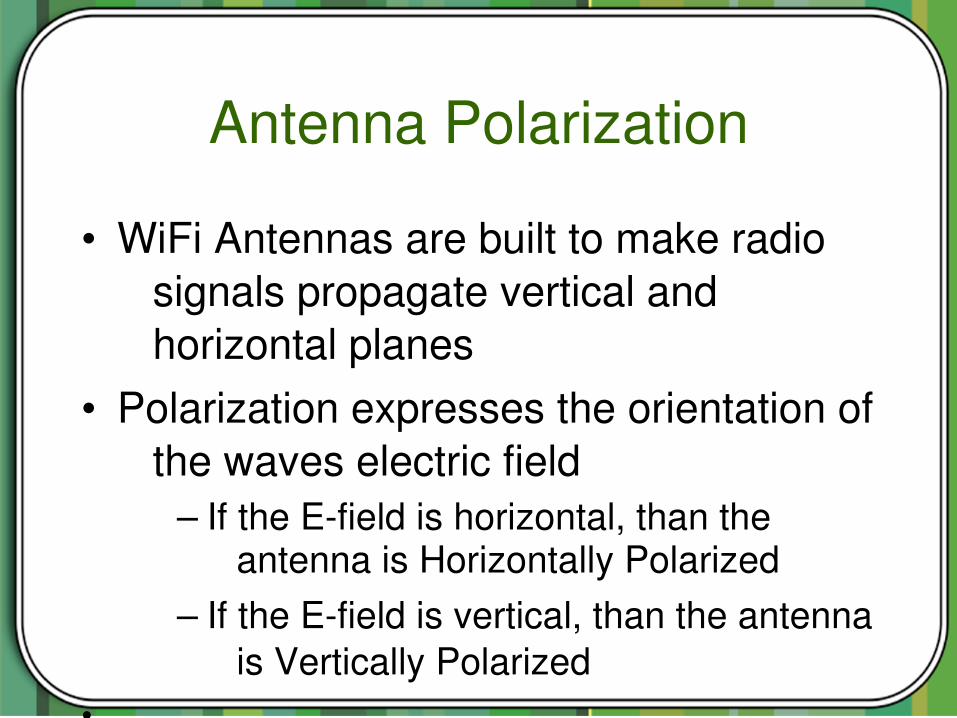
Antenna Polarization
• WiFi Antennas are built to make radio signals propagate vertical and horizontal planes
• Polarization expresses the orientation of the waves electric field
– If the Efield is horizontal, than the antenna is Horizontally Polarized
– If the Efield is vertical, than the antenna is Vertically Polarized
•

Antenna Polarization
• Polarization is used to:– Increase isolation of unwanted
signals source and hence reduce interference
– Define different coverage areas by reusing frequencies
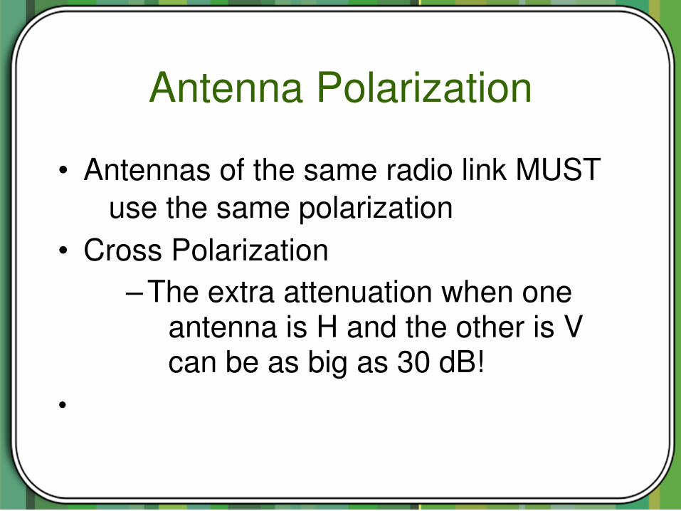
Antenna Polarization
• Antennas of the same radio link MUST use the same polarization
• Cross Polarization– The extra attenuation when one
antenna is H and the other is V can be as big as 30 dB!
•

Antenna Polarization
• Using Several Parabolic Antennas on the same mast
• Cross Polarization
• Source www.radioscanner.ru
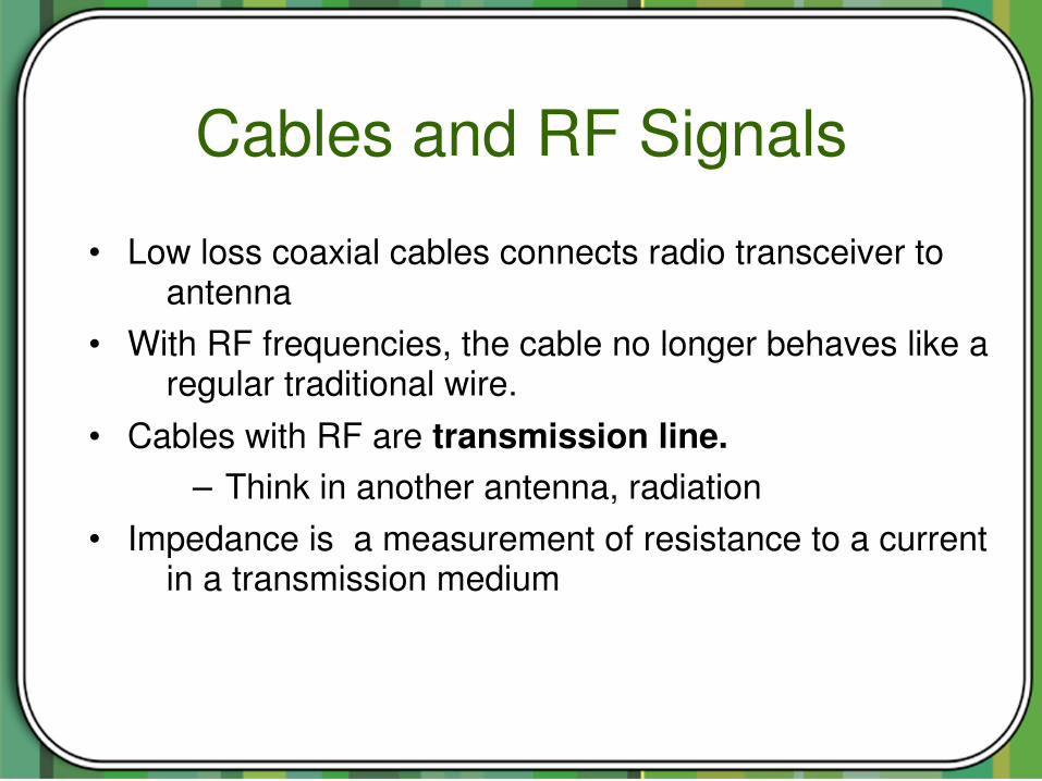
Cables and RF Signals
• Low loss coaxial cables connects radio transceiver to antenna
• With RF frequencies, the cable no longer behaves like a regular traditional wire.
• Cables with RF are transmission line.– Think in another antenna, radiation
• Impedance is a measurement of resistance to a current in a transmission medium
Cables and RF Signals
• Impedance remains constant with independence of the cable length
• Maximum transfer of energy between the transceiver and the antenna only takes place when all the circuit elements match the same impedance

Cables and RF Signals
• In data communication equipment (including WiFi) the impedance is always 50 (Ohm)Ω
• If not, the radio signal (energy) will reflect back into the transmitter rather than into the antenna
Energy Loss in Cables
• The coaxial cable introduces a signal loss between the antenna and the transceiver.
• The signal is attenuated towards the antenna and the signal collected by the antenna is attenuated on its way back to the receiver.
• Typical cable loss for WiFifriendly cables: 0.07 – 0.22 dB/m (but can be more!)

Energy Loss in the cablesCable type Loss [db/100m]
RG 58 ca 80100
RG 213 ca 50
LMR200 50
LMR400 22
Aircom plus 22
LMR600 14
1/2” Flexline 12
7/8” Flexline 6,6
C2FCP 21
Heliax ½ “ 12
Heliax 7/8” 7
Energy Loss in the cables
• When you choose a cable you need to consider several factors:
– How long cable do you need?– Do you need to bend the cable in sharp
angles? – Do you need to transport/bring the cable
from overseas?

Connectors• Endless number of types• Good connector: 0.1 dB• Bad connector: several dB• Invest in good connectors
Fig. Source: Connexwireless
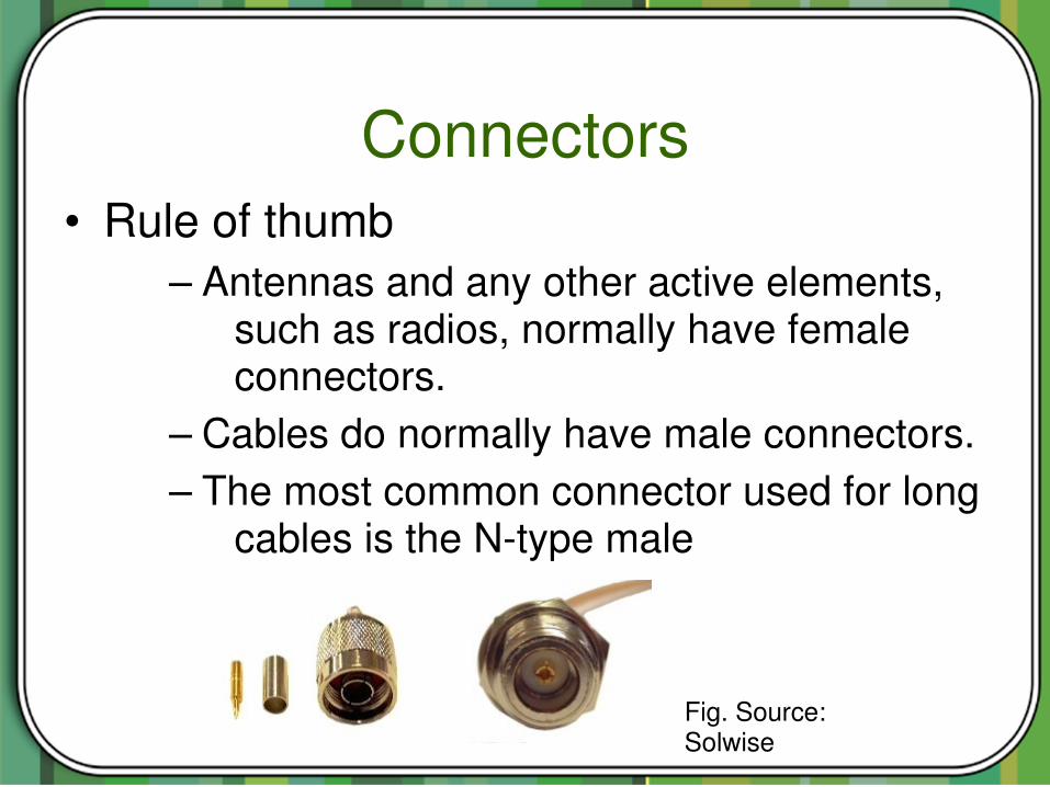
Connectors• Rule of thumb
– Antennas and any other active elements, such as radios, normally have female connectors.
– Cables do normally have male connectors.– The most common connector used for long
cables is the Ntype male
Fig. Source: Solwise
Pigtail/Converter
• Pigtail matches two types of connectors • Loss of 0.20.6 dB• Small length cable patching
– A radio with an antenna – A radio with a long run cable
• Converter: One unit with two types of connectors: 0.1 – 0.2 dB

Pigtail/Converter

Conclusions Antennas
• Antennas:– Start with Link Budget to see what you need
in order to get enough margin– Be spectral efficient and follow the power
regulations– Sectorize the access points, tilt antennas to
match your coverage area
Conclusions Cables
• Cables– Take care of your cables and connectors as
they are always a point of failure.– Microwave cables and specially connectors are
precisionmade parts.– Be sure to know how much you can bend your
chosen cable and never step over a connector!
Final Conclusions
• Good choices in equipment depends on your ability to understand radiation patterns, link budgets and the type of service that you aim for.

Sources: this presentation from http://wirelessu.org
http://creativecommons.org/licenses/by-nc-sa/3.0/