antenna tips page 1 of 31 source :...
TRANSCRIPT

Antenna Tips page 1 of 31Source : http://www.funet.fi/pub/dx/text/antennas/antinfo.txt
Antenna ArticlesCollection of short articles relating to all manners of antennas. These articles are the hard work of Wayne SarosiKB4YLY (995 Alabama Street, Titusville, FL 32796)
SUBJECT: Circular Polarized AntennaThere has been a request for a series on 'CP' antennas. The term 'CP' eluded me at first as I was not
familar with the abriviated designator for circular polarization. At work, we just use the entire words. I'm goingto begin this ten part series with the basics. After researching CP designs with a few engineers and fellow hams, Ifound that they knew very little about the subject. I also found I didn't know quite as much as I thought I didabout circular polarization. So starting at the begining will help all out.
First, let's discuss the circular polarized wave. There seems to be conflicting standards used by the worldof physics and the IEEE. I found this to be true in four reference manuals including the ARRL AntennaHandbook. At least it's stated right up front but biased according to which text you read. We will follow theIEEE/ARRL standard in the following series for obvious reasons. There are two types of circular polarization;right and left. All of us agree up to this point. According to the ARRL Antenna Handbook, the followingstatement:
'Polarization Sense is a critical factor, especiallyin EME work or if the satellite uses a circular polarized antenna. In physics, clockwise rotation of an
approaching wave is called "right circular polarization," but the IEEE standard uses the term "clockwise circularpolarization" for a receeding wave. Amateur terminology follows the IEEE standard, calling clockwisepolarization for a receeding wave as right-hand.' Confused yet? I read it five times before it sunk in. Physicsuses 'right', IEEE uses 'clockwise', the ARRL follows the IEEE and calls it 'right-hand'. Just remember the 'right-hand' or 'clockwise' is for a receeding wave or one that is going away from you.[You have one minute to flap your lips with your finger and read the above paragraphs again.] ;-)
Ok, now we know a reference that we can base "right-hand circular polarization" on. Now I have anexperiment for you to try. Obtain a hard rubber ball from the kids or a neighbor's kid and try this: drop the ballwith a "right-hand polarization" spin and watch which way the ball spins as it bounces towards you. You'll find itwill spin in the opposite direction [this works great with a super ball]. This is exactly what happens in EMEwork. The "right-hand circular polarized" signal returns in the opposite polarity. The same holds true for passingsatellites using circular polarization. An approaching satellite's circular polarized wave will reverse as it passes.
Another quote from the ARRL Antenna Handbook states that the circular polarized wave and a linearwave are mathmatically special cases of an elipical wave. When the magnitudes are the same and phase anglesare 90 degrees in time, we have circular polarization. One antenna that uses circular polarization is the helicalantenna. It comes in two flavors, LHCP and RHCP for left and right hand circular polarized. As stated on theprevious posting, RHCP is a clockwise rotation as the wave receeds from the point for transmission. The RHCPhelical antenna is phsyically configured this way with the turns of the helix rotating clockwise away from themounting point.
The LHCP helix is phsyically configured counter-clockwise away from the mounting point. The helix isan end-fed antenna. For satellite and EME work, both LHCP and RHCP helix antennas are required for propersignal reception as the polarization changes when the satellite passes overhead or the returning signal from anEME transmission is received. Below are some other CP antennas for you to look at that are used at the KennedySpace Center. For a refernce of Helical Antennas, read the ARRL Antenna Handbook, pages 19-22 thru 19-33 inthe 16th edition. To repost the figures here would require several listings, but an overview will be coming in theseries.
In general, the helix is very predicable in gain and pattern. Introduced in the 40s, the helical antennaresembles nothing more than a large air-wound coil with characteristics showing its electrical pattern. There areother types of antennas with circular polarization such as the cavity backed sprial which comes in the sameflavors, LHCP and RHCP. These type of antennas are commercial grade and seldom used in the amateur world.One strange antenna is the 'twisted yagi' of which I am still trying to find some info on. I don't know if the

Antenna Tips page 2 of 31Source : http://www.funet.fi/pub/dx/text/antennas/antinfo.txt
name is correct, but I have heard it refered to that way. The twisted yagi is nothing more than a yagi with theelements offset in a continous rotating fashion. Each element is positioned about 30 degrees from the one before.They can get rather long for the designed frequency. I'll see what I can dig up on this type.
For true CP design, the choice of antennas are limited. Elipical patterns are most used for satellite andEME use. We can look into these antennas also if there are no objections. HELIX: Well, I promised somefigures for all of you concerning the helix antenna as it is probably the most popular CP antenna. Afterresearching the subject of helix antennas, I found the design parameters are all basically the same with the onlydifference being the variables used to describe the different values. The ARRL Antenna Handbook has a verydetailed construction dialog. There are plenty of pictures and easy to use formulas. A couple of technical antennatheory books at work and from college tend to bury themselves in mathmatical theory removed from practicalapplication that we require for working models.
Theory is good, don't get me wrong, but theory at college level for amateurs that have not been tocollege, is not good for contruction. It assumes too much on the average amateur in the area of math. For now, Iwill give the basic design parameters for the helix antenna and then conclude with the some information on thecavity backed spiral. In the ARRL Antenna Handbook, 16th ed, 19-22, provides about the best description of ahelix and how to build one. The Helix has two componets; a ground plane and the helix. It is fed with a coax.The diameter of the ground plane is 0.8 to 1.1 wave lengths in diameter. This section is connected electrically tothe coax braid. Since ASCII does not provide all those neat little greek letters I'll have to improvise here.
C is the circumference of a coiled turn.S is the spacing between one coil and the next.G is the diameter of the ground plane.g is the gap between G and the begining of the coils.AR is the axial ratioD is the diameter of a coil turn.n is the number of turnsL is the length of conductor in one turn. w is the wave length.Z is the impedance in ohmsGain is the gain of the antenna (now that was a smart statement)HPBW is the half power bandwidthC = 0.75w to 1.33w where w = 984/fMHz in ft or 300/fMHz for metersS = 0.2126*C to 0.2867*CG = 0.8w to 1.1wg = 0.12w to 0.13w at 45 degrees to the ground plane.Note: This is similar to the distance between a DE and D1 in a yagi.AR = 2n+1/2n which should be as near to unity as possible. The closer you can get this ratio to one thecloser you will have a pure circular pattern.D = C/3.1415927 => 0.2387w to 0.35wn => use AR until you get a balance between a good ratio and a practical length you can handle.AR = 2n+1/2n => n=6 then 13/12 = 1.083333, n=3 then 7/6 = 1.1666, n=10 then 21/20 = 1.05. As youcan see there isn't a vast improvement between 6 and 10 turns. n=15 then 31/30 = 1.03333.
Not much more here either.
L = sqrt[(piD)^2 + S^2]Z = 140*C ohms which is 0.75w*140 to 1.33w*140 ohmsHPBW = 52/(C*sqrt[n*S]) degreesGain = 11.8 + 10log((C^2) *n*S))First nulls beamwidth = 115/(C*sqrt[n*S]) degreesPitch angle between the coils should be 12 to 16 degrees or arctan(S/C)
Heres some stats from an antenna we use at the EMLab. The antenna is a broadband cavity backed spiral antennamade by EM systems, model A2200. It's good from 1 to 18 GHz with an SWR of 1.8:1 over the entire band.

Antenna Tips page 3 of 31Source : http://www.funet.fi/pub/dx/text/antennas/antinfo.txt
Diameter = 6.85-ingain = 0 dB minimum 5.5 dB maxPolarization = LHC or RHCaxial ratio = 3 dB3dB Beam width = 80 degreesMIL-E-16400 class 2 equip.
SUBJECT: Gamma modification for better symmetry & gainThis subject has been discussed before on the HAM echo and will be further discussed here with more
detail. Most gamma matching devices are mounted to the side of the driven element. This technique is good formatching, but does not provide good pattern. The symmetry of the antenna pattern is distorted to the side of theantenna that the gamma match is located on. Several antenna brands were tested with all brands tested showingthe same result. The pattern produced by the side mounted gamma is kidney shaped. This shaping accounts forthe fact that you can hear a signal on one side of the beam and not the other. The side to side ratio is notconsistant. In the case of horizontal beams, the gamma hangs down, wasting gain and affording a loss of signalreception that could otherwise be used.
What would it take to move this lost antenna gain and sensitivity into the area of the pattern that could beutilized? Not a whole lot in fact. The entire modification can be done in under a half an hour and for less than adollar. What results is that the wasted gain to the side of a vertical beam is moved forward and the wasted gainunder a horizontal beam is moved into the horizontal plane forward. The average gain increase is near 1.5 dBover the previous gain rating of the antenna. What this means is that if your antenna produces 10 dBi it will nowproduce 11.5 dbi. Your Cushcraft eleven element yagi rated at 13.2 dBi will now produce 14.7 dBi. 13 dB isequal to a gain of 20, 16 dB is a gain of 40, so you can see the improvement.
To accomplish this, you will need to remove the gamma match from the antenna. Remove the di-electricinnards and replace with a piece of RG-8 foam di-electric about 3-in longer. Pivot the tuning arm 90 degrees sothat it faces the first director. Insert the gamma back into the tuning arm. Now, solder to the center pin of thecoax feed point. If your coax feed point is a threaded section, crimp or solder on the appropriate fitting, thentighten the nut. You will need to retune the antenna at this point. Fairly easy? The results are incredible.Increased gain, better symmetry, better side to side and front to back ratios. This modification has been used herefor over a year. When I turn the beam to the side of a signal, the results blow away any commercial beam. Mynine element yagi can keep up with the commercial eleven element antennas. Try it out. I'm sure you will enjoythe change.
SUBJECT: Hidden Apartment HF AntennaBottom floor dwellers have some advantages over dwellers on other floors concerning HF antennas.
Single unit condo & PUD dwellers fall into this area. Dwellers in the mid-floor(s) have it the toughest. And topfloor dwellers have other advantages the first two don't. HF antennas are large and trying to hide one can belike trying to hide an elephant. Many hams try different configurations, snap together antennas, wires, and flagpoles to conceal their antennas. Some work out, but most get caught in the end.First, let's look at what you can and can't have. Most restrictive housing areas have a long list of items you can'thave. Clothlines, TV antennas, sheds, flags, BBQ grills, etc. And most of all, the all important HF antenna. It hassomething to do with nice surroundings.
Make a list of these items and place them in a column on the left side of the page. Next, list what you canhave and list them in the center of the page. Next, list the items that are readly available in the area of your home.Such items are trees, gutters, vents, fences, etc. Look closely and don't leave anything out. A hidden HF antennamust be just that, hidden to the naked eye, even at a point blank range. Next, list the areas that you have a readyaccess to. If you can get to the roof, write it down. How about the attic, basement, trees, etc, without much noticeby your neighbors. Most HF antennas are discovered not because of their design or placement, but rather aneighbor spies the ham installing the antenna or at least doing something out of the ordinary.
EX: Creeping around on the roof, on a Saturday afternoon, is going to draw attention. Flinging wires overtrees is sure to draw some attention. The big point here is not to install the antenna by looking like yourinstalling an antenna or doing something out of the ordinary. There are some new designs out on the market such

Antenna Tips page 4 of 31Source : http://www.funet.fi/pub/dx/text/antennas/antinfo.txt
as PVC vent pipe antennas for 2m. But for now we'll stick to HF. Most contracts for condo / PUD dwellers willallow bird feeders. And even apartment dwellers on the bottom floor can benifit from this design. I'll give a briefdescription here of the Bird Feeder antenna and discuss it further in later postings. The Bird Feeder HF antenna isa vertical cage wire antenna. A 'What?' you might ask. Imagine if you will eight flexible wires, evenly spaced in acircular pattern, much like a ground plane. Draw these wires vertically to form a wire 'tube' and connect themtogether with a ring at the top. Now imagine these wires inside a telescoping PVC mast. Top that off with a birdfeeder. Now, instead of a ground plane system with radials you have to put in (the neighbors are watching), youhave this 'wire tube' constructed as a vertical dipole. At 10m, the Bird Feeder antenna is a mere 17' tall whenraised. What would the neighbors say? Or for that matter the manager?
"I raise it up for the birds to get into and it keeps the squirels out too. And look, I can take it out when I'mnot using it or the weather is bad. Boy, I really like watching the birds from my window. Did you know that ..."And then go on about some rare, but not unbelievable birds that frequent the feeder. Buy a book on the subjectwith some pages tagged to show them what you've seen so far. At worst, they'll think you're a flake and leave youalone. Next, go in and tune up 10m and catch some rare DX instead. What do you have to actually put into theground? Your coax and a PVC pipe to hold the mast up. Make it low in the ground and cap it so the mowerdoesn't take it off. For the most part, you can leave it up. But do remember to put so seed in the feeder once in awhile!
Bird Feeder Antenna IINow, I admit, this design sounds a bit far fetched, but it works. The vertical dipole, inside the PVC push-
up, is invisable. It moves up and down and can be removed without drawing attention to the fact that it containsan antenna. The flagpole design has some problems. Not all PUDs, condos, or apartments allow flagpoles. Theyrepresent a permanent fixture.Not all associations or managers are that patriotic. Although you can pack a goodvertical in a flagpole, there is the problem of radials. You can run the vertical without radials, but that's anothercompromise. The design for the Bird Feeder Antenna is very simple. Drawing it here is another problem. ASCIIGraphics really do not exist, so a description is in order. You can build the vertical dipole without much trouble.The dipole consists of up to 16 wire 1/4 wave elements. There are eight on each leg of the dipole. You may useless, it's up to you. You know the bandwidth of a wire dipole and you know the band spread on 10m. If you are ageneral or above, you will want the extra wire elements to give you the bandwidth you need. First, let's look atthe PVC tubular mast / bird feeder support. Most hardware and home improvement center have PVC tubing. Likethe steel counterparts, the mast will be graduated (large at the bottom and smaller at the top. I'm not going torecommend any sizes here as availability at your store is going to dictate what sizes you will need. I will state thethe top tube should be 2" in diameter or better. You will need that size to support the bird feeder and give the mastsome strength. ___ | | <------- Attach upper ring | | inside | | |_| <------- Attach next ring | | inside | | | | |___| <------- Attach feed ring inside | |<------- Attach feed ring inside | | | | |_____| <------ Attach feed ring | | inside | | | | | | |_______| <------ Attach bottom ring inside

Antenna Tips page 5 of 31Source : http://www.funet.fi/pub/dx/text/antennas/antinfo.txt
The wire elements are attached in a ring format, evenly spaced, in a 360 degree pattern. Locations arenoted in figure one. This allows the dipole to be folded up when the mast is lowered. More than eight wires oneach leg of the dipole tends toward snags when raising and lowering. Dipole wire element sizes are calculated by246 / f Mhz. But I recommend shorter lengths if eight elements are used. A BALUN can be inserted, but is notnecessary. I feeder coax is needed from the dipole feed to the base of the mast. A UHF bullet (female to female)to attach your coax to.
How to lay the coax without looking like you're doing it:The base piece for the bird feeder mast should be one size larger than the bottom section of the mast. The
mast should be able to side in a snug fashion, but not too tight. Since you are installing a 'bird feeder', youshouldn't have any problem explaining what you are doing. Simply lay the bird feeder and mast right out in theopen. Your nosey neighbors will know exactly what you're doing (almost). The coax is the tough part. Trenchesare out of the question. Use a sidewalk edger (manual) and make a thin cut in the grass. If you have otherobsticles, you will have to deal with that when you come to it. The object is to do it when the neighbors are notgoing to notice. The thin cut in the lawn will not be seen and will 'heal' quickly. A tricky technique is to use awheelblade on a handle. It will look like you are using a measuring device. The cable can be laid into the cut atdawn, when you are filling the bird feeder. Stepping on the cut lawn on the way back seals the cut. Now you're inbusiness.
Mobile Resonators as HF hidden antennasMobile resonators are small and easy to hide in comparison to a full size HF antenna. They have there
own faults as well. They require a good ground plane when not attched to a vehicle. Experiments done here withmobile HF antennas have shown good results when used as a base station antenna. The most obvious and easiestinstall for a mobile HF antenna is the installation it is designed for. Mobile! To take advantage of the 'noantennas' rule at most PUDs / condos / apartments, the designed mobile installation is best. In addition to this, acoax can be run from the location of the mobile to the dwelling for indoor operation. This provides a mobile/baseoperation with just the installation of the coax. This concept also gives the operator the alibi needed ifinterference is experienced by the neighbors. When they look out to see if you're in the vehicle, nobody is there.
This design is good for bottom floor dwellers in apartments and any 'sneaky' mid-floor dwellers who canweasel a coax to their apartment. Top floor apartment dwellers can hide the resonators in PVC pipe and installthe antenna on the roof of the building, if possible. It would need to look like a vent pipe. I've seen some designsthat even pop out of drain pipes. This design may be a little too much for most amateurs. Roof and tree mountingcan be difficult at best. Installing these antennas can be next to imposible for most dwellings. If you decide toinstall a mobile resonators in other than the designed location, a good ground plane is a must. This one factor maybe your undoing in the stelth antenna concept. Painting the antenna to hide it can help. For night operation, flatblack or flat dark grey is recommended. Daytime ops require a background blending scheme. Further placementdesigns of this antenna is in works.
SUBJECT: Indoor antennas
HF Indoor Antennas:This can be fun. Imagine packing a 20m beam into an apartment! OW! Imagine your XYL's reaction! OW!Imagine trying to turn it! LOOK OUT! Here, I'll discuss some pratical indoor antennas that can be built byanyone.
Antennas include: o HF foil antennas o VHF/UHF discones o Wire beams o Attic VHF/UHF rotatables o Tape antennas (TNX Jim, for the idea) o Telescoping VHF/UHF indoor beams.

Antenna Tips page 6 of 31Source : http://www.funet.fi/pub/dx/text/antennas/antinfo.txt
HF Foil AntennasHF foil antennas are too weak in their physical construction for outside use. Foil antennas are just what
the title implies, foil. They are made from ordinary aluminum foil, the kind used for heavy duty cooking, such asroasting a turkey. This antenna goes in the attic of your home or condo. Apartment dwellers may have a timewith this antenna depending on their location within their complex. Materials needed are two to three rolls ofaluminum foil, copper tape with electrically conductive glue, a staple gun and staples, and coax with connector.By stapling the foil in a loop or dipole configuration on the attic rafters, a simple antenna can be formed.
======================== ========================== || balun if desired | | | coax to shack
==================================================== | | | | | | | | | | | | ======================== ========================== || Balun if desired | | coax to shack
These two configurations are excellent when used with a tuner for the various bands on amateur radio andSWL listening. They are cheap to install and can be made into other configurations, by the amateur, if desired. Arelay can be installed to provide dual antenna configurations if needed. With this device you can switch between adipole and the loop for different propagation conditions. Size and shape is dependent on the attic structure.
Indoor Antennas for HF & VHF/UHFI thought I would conclude the HF foil antenna here and move on to another subject. Connections from
the foil to the coax or BALUN are via the copper tape. There are copper tapes available on the market that areused for EMI applications. These tapes are expensive so if you can get a piece of some of that tape from a buddy,it will work wonders for you. Otherwise, there is a trick with regular copper tape and the aluminum foil that youcan do. It's a simple folding technique that insures a good connection and yet requires no soldering except for thecoax / BALUN connection.
=========================================== Aluminum foil |-----------------------------------|| | ==================================== |------------------------------------------- Copper tape
This folding method insures good contact on more than one surface. One warning, do not leave air gaps asit will have a capacitive effect. Solder doesn't stick to Aluminum foil very well. With enough heat, you cansolder anything. Too bad the aluminum foil won't hold up at that temperature and neither will the solder. Younow can solder leads to the BALUN or solder the coax direct to the copper tape. For an indoor antenna, the foilantenna works rather well. It can out perform a vertical and pull in the weak ones with ease. I think you'll find itone of the most inexpensive antennas you can build yourself.
VHF/UHF Discones

Antenna Tips page 7 of 31Source : http://www.funet.fi/pub/dx/text/antennas/antinfo.txt
The discone antenna is a rather unique antenna for VHF and UHF. The discone has no gain to speak of,yet can provide the user with a range of ten times the design frequnecy for reception and transmitions. This meansthat a discone designed at 140 MHz will work fine up to 1.4 Ghz. Hiding the discone outside may prove to bequite a feat. Unlike most antennas, the discone has a large skirt and is tall to boot. It's shape can draw attention.If you can place the antenna outside, it will give you excellent coverage over it's range. Inside, the discone workswell minus the attenuation caused by the building it's in. There are many Discones available on the market if youchoose not to build one. Building one can be fun if you take the time and lay everything out ahead of time.There are a couple items I would like to point out about discones.
1) The gap between the top-hat and the skirt is critical.2) The area under the skirt is a null to the antenna.
Design parameters are easy.ο The top-hat diameter is: (0.1778 * (984/f MHz))*12
EX: at 140 MHz --> (0.1778 * (984/140))*12) = 15-inο The diameter of the skirt, at the base, equals the length of the skirt elements. This gives the user the
closest impedance to 50-ohms. Thus a skirt element length is: (0.2675 * (984/f MHz))*12)EX: at 140 MHz --> (0.2675 * (984/140))*12) = 22.56-in
ο The gap is: (0.007114 * (984/f MHz))*12)EX: at 140 MHz --> (0.007114 * (984/140))*12) = 0.6-in
A tin funnel works well as a starting base that brass skirt elements can be soldered to. An SO-239 chasisconnector can be fit into the cutoff funnel end and the top-hat soldered to the center pin of the SO-239.Insullating spacers can be used to strengthen the gap. I've used a brass screw that was soldered between the centerpin and the top-hat, but you can use anything that you can solder. I have a motorized discone in works. Thestepping motor will be incorporated to change the gap, to match the frequency, for best SWR.
Wire beams, indoor antennasFor many of us, the antenna is the biggest problem for most hams. Hams have to contend with neighbors
and the XYL in order to pursue their hobby. An interesting HF and VHF idea I've seen used is the wire beam.The wire beam is unrolled and suspended in the direction required for operation. After the operation is complete,the wire beam is rolled up and stored for the next time. This type of beam is excellent for 10m and up to 1.25 m.You may be able to set up a wire beam for frequencies below 10m if you have the space to do so. This antenna isalso excellent for suspension in an attic.
A simple model is shown below:
R DE D
-----------||--|-------------|----------|--||----------- || | | | || || | | | || || | | | || -----------||--|-------------|----------|--||----------- || | | | || || | | | || || | | | || -----------||--|-------------|----------|--||-----------
Aside from the elements, the rest of the configuration is non-conductive. Wooden dowel supports areoutside the ends of the antenna and string/rope can be used to support the elements. The wooden dowels are notrequired if suspension is taught. You can see that variations of this set-up can be incorporatedto accommodatemost any frequency from 10 to 1.25 meters.
Attic VHF/UHF Rotatables

Antenna Tips page 8 of 31Source : http://www.funet.fi/pub/dx/text/antennas/antinfo.txt
In many instances, a ham can mount a VHF or UHF beam in the attic, on a rotor. They can achieve goodresults depending on their location and height off the ground. Antenna size limitations are soley dependent on theavailable room in the attic that allows rotation of the beam without hindering it's rotation. To check the attic forthe maximum size antenna, the ham must first enter the attic and measure the distances in the area planned for theset-up. Trusses, electrical wiring, air conditioning / heating ducts, and the items that are stored up there, can allplay a factor in the actual antenna size. Finding your antenna with a pair of long johns dragging off the front endis not a pretty sight. After measuring the area in the attic, the antenna size and height off the attic cross memberscan be accomplished. Remember to allow for a base to accommodate the rotor. This too must be calculated intothe system. Building a sleek system, to rotate two or three small beams, can be dashed, when the system will notturn because of an oversight in the measured values of the attic area in question. Turning radius is the importantfactor. Each antenna forms a rectangle ABCD where the maximum distance is AD or BC.
A------------------------------------B | | | | ----|----------------------------------|---- BOOM | | | | C------------------------------------D
For horizontal antennas, the turning radius is from the mounting point to the tip (either side) of the longestelement. Multiple this figure by two for the turning diameter of the antenna. For vertical antennas, the trussangle places the biggest problem as the height from the boom to the tip of the refector (B or A). In essence, thiswill shorten your boom length or require a lower rotor mounting. These tips will help the Amateur avoid anyproblem before getting the system in the attic.
Indoor telescoping beamsOne problem I have encountered from Hams living in apartments is the space to place a VHF/UHF
antenna. This concerns operation of the beam from a bedroom or porch. In these cases, the Ham can not keepthe antenna up and must remove the antenna after he or she finishes. Using telescoping elements can solve theproblem. Adding a two or more section boom can further the portablilty fo the antenna making it idea for fieldday, camping, or travel also. Dimensions for beams have been discussed earlier, so I won't rehash them here. Thebest portable and quickest for set-up is the four element VHF antenna. A two section quick clamp boom withmounting flange for a camera tripod provides the base. Each element contains two telescoping units and a snapon fitting for attachment to the boom. The driven element has shorter telescoping units to preserve the gammamatch section as one piece. The antenna described here can be stored in a briefcase save the camera tripod. AVHF four element antenna can provide 9dB of gain for the apartment dweller.
Tape antennas on sun-film windows:Using the tape loop, discussed earlier, I tested the antenna on two types of sun-film windows. The first
was a plastic film, often used in states such as Florida. There was no significant pattern or gain change for theantenna. The second type of film is the metal film sun screen. Results here were dramatic. The pattern wasseverely disrupted as well as SWR. Be sure that your window films are not the metalic type if you plan to useindoor VHF/UHF antennas pointed out the window. The metalic film acts like a reflector to the signal.Attenuation is a strong factor concerning propagation. Some plastic films appear metalic, but may not be.
Tape antennas on screened windows:There are a three types of screen used as screening for windows. Plastic, fiber, and metal. The first two
show some attenuation of the gain and pattern shape is similarly effected. Basically, the addition of the screenframe effect the VHF spectrum greater than the UHF spectrum. The screen frame size is near the size of VHFloops at frequency. Metal screen acts similar to metalic film with greater effect. Using the top portion of thewindow is the best bet unless you don't have windows like the type used in the Northern States.
SUBJECT: Log Periodic Dipole Array (LPDA) Design

Antenna Tips page 9 of 31Source : http://www.funet.fi/pub/dx/text/antennas/antinfo.txt
This antenna was designed to operate from 13.8 MHz to 28.8 MHz. The antenna was to cover themajority of the USAF MARS frequencies yet give the operator a smaller log periodic than the commercial types,that had reasonable gain, and was cost effective to build. All design formulas are taken from the ARRL AntennaManual. The antenna did not turn out as planned. The frequency range actually went from 13.5 MHz to 29.5MHz with SWR less than 1.8:1. Most SWR readings were less than 1.5:1 across the band. The weight was asurprize also. I expected 100 pounds plus, but actually was under 63 pounds.
SPECIFICATIONS:
Boom: 22-ft, 3-in diameter, aluminum. Number of Elements: 10 Feed: Balanced BALUN: 4:1 Weight: 62-lb Windload: near 9 sq.ft. Cost: About $200.00 Note: $150 for element insulators from HY-Gain. $50 for misc. Tubing, boom, etc from old antennas discarded by fellow hams, CBers, and field day. Time: 80-hrs, including install. Design Bandwidth: 13.8 MHz to 28.8 MHz Actual Bandwidth: 13.5 MHz to 29.5 MHz*, Highest my TS-430S would go. SWR MAX: 2.1:1 SWR AVE: 1.4:1 SWR LOW: 1.1:1, all taken on an MFJ-986 Differential-T Tuner/SWR/PWR meter. EST GAIN: 6dB PWR Handling: Max Legal. Turning radius: same as 20m, 3 element Yagi Height off the ground: 35-ft minimum for best results (half wave at 14 MHz).
ELEMENTS: (Half element lengths given and quantity) Note: Elements start at rear, longest first.
L10: (492/13.8)/2 = 17.826-ft, quantity (2) L09: L10 * 0.9 = 16.043-ft, quantity (2) L08: L09 * 0.9 = 14.439-ft, quantity (2) L07: L08 * 0.9 = 12.995-ft, quantity (2) L06: L07 * 0.9 = 11.696-ft, quantity (2) L05: L06 * 0.9 = 10.526-ft, quantity (2) L04: L05 * 0.9 = 9.473-ft, qauntity (2) L03: L04 * 0.9 = 8.526-ft, quantity (2) L02: L03 * 0.9 = 7.673-ft, quantity (2) L01: L02 * 0.9 = 6.906-ft, quantity (2)
ELEMENT SPACING: d(L10-L09) = 2*(.5(L10 - L09) cot(0.5 * apex angle)) The cot(0.5 * apex angle) = 2. Thus: d(L10-L09) = (L10 - L09)*2 AND: d(L09-L08) = d(L10-L09) * 0.9
d(L10-L09) = 3.566-ft d(L09-L08) = 3.209-ft d(L08-L07) = 2.888-ft d(L07-L06) = 2.599-ft d(L06-L05) = 2.339-ft

Antenna Tips page 10 of 31Source : http://www.funet.fi/pub/dx/text/antennas/antinfo.txt
d(L05-L04) = 2.105-ft d(L04-L03) = 1.895-ft d(L03-L02) = 1.706-ft d(L02-L01) = 1.535-ft
0.5 * Apex angle: 26.565 cot(0.5 * apex angle): 2
Further detail is given in the ARRL Antenna Book under Log Periodic Dipole Array.
Mounting: 1/4-in aluminum plate 10-in X 10-in (4) U-bolts to fit 3-in boom & mast 1/2-in stainless steel bolt, spacers, lockwashers and nuts.
--------------------------------- | | | 0 0 | | | | 0 0 | -----------------|-----------------------|-------------------------- | 0 | -----------------|-----------------------|-------------------------- | 0 0 | | | | 0 0 | | | ---------------------------------Bolt through center allows for pivoting of mast for element placement or repair. Bolt configuration: Nut-L.Washer-Washer-Boom-Washer-Nut-Washer-Plate-Nut
Author's Notes:I would first like to point out that I am an aluminum tubing pack rat. I have had enough antenna parts to
build a set of three element yagis for our team on field day. Antenna tubing is fairly easy to come by if you takethe time to hunt it out. Many hams have tubing they are begging to get rid of. There are hams that become SKsand the widow would be more than happy to have you remove the antennas. There are beams that have taken adive during a wind storm or some that have been replaced because of bad traps or corrosion. Much of the tubingI have is old. It can be restored to near new condition with the wire wheel on a workbench grinder. This isprobably the single factor in which I was able to build this LPDA for under $200. Tubing is expensive and pricesvary from state to state. You can beat the system by scrounging the tubing and reconditioning it. The insulatorscan be procured from Telex/HY-GAIN at $15 each plus shipping.Anything else can be procured from True Valueor Ace hardware. Use Stainless Steel hardware for everything you do. It's more expensive, but saves you in thelong run.
Back to the antenna...I have watched the SWR readings and made notes of some of the propagation features of the antenna.
The antenna's orginal design came from an older ARRL Antenna book and the ARRL Handbook (87). Evidentlythe design has been around since dirt was invented. To date, the SWR has had minor changes, some for thebetter and some worse. There are no SWR readings above 1.8:1 and that is one feature that has not changed.Most of the other changes, in SWR, have had little or no impact on the operation. These changes may be theresult of temperature changes as we have had readings in the forties here on occation. Front to Back notes: TheLPDA does not have the FB ratio that a good yagi does towards the bottom of its range, but at high end, theLPDA runs rings around the yagi. Reception: I've run yagis here for years and I can honestly say that the LPDA'hears' better due to the capture area of the antenna. Transmission: With the low SWR across the HF Band, theLPDA works well with or without a tuner. Since I operate MARS Phone Patching for the USAF, I have had

Antenna Tips page 11 of 31Source : http://www.funet.fi/pub/dx/text/antennas/antinfo.txt
numerous oportunities to query operators in South America and the US. All report that the signal is as good asthe three element monoband yagi I used before. These operations take place above the 20m band but below the17m band. When operations take place on bands above 20m, the LPDA shows improvement in gain.
Weathering: The LPDA has been subjected to wind gusts of 50 mph plus with no ill effects. The LPDAis however a great haven for the many birds we have here in Florida. I believe they have a Bar & Grill up there.At one time, there were no less than 63 birds on the antenna. After a quick carrier, there were zero. Lucky forthem, they do not roost up there at night. My phone patching output is the legal limit. Overall, the LPDA is theantenna for me. The design was the hardest and even that can be done with a handheld calcuator and the text inthe handbook. Previous postings provide the reader with all the precut values needed for operation from 13.5 to29.5. The 22-ft boom is about the same size as a 20m monobander. If you can put up a 20m monoband yagi, thenyou can put up a LPDA. No traps, coils, or power limitation except the balun.
SUBJECT: Tape AntennasThanks goes to Jim Grubs for the idea.
Tape antennas seem to be an interesting way for apartment dwellers, travelers, and others who need aquick antenna that can be used locally. For these experiments I used copper tape, 1/2-in wide for my tests. Thefollowing antenna types were tested:
ο J-Poleο Half-wave Dipoleο Full-wave Loop
Tape antennas are not new. I haven't seen much about tape antennas with the exception of SAREX, usedaboard the Shuttle. Even this antenna was quasi-tape-type. In general, the tape antennas had some interestingpropagation results due to the location of testing. Locally, the antenna is excellent. Within a mile or two, theantenna works as well as an outside antenna. But, due to the single floor building I work in these results may bebetter if the antenna was located on a higher floor. Propagation outside the local area was a function of whichway the window faces. Generally, the antenna pattern was not omni, but rather an attenuated omni pattern to theside where the building faces.
Figure 1: Signal levels in dBm.
-21 -20 -17 1 12 16 18
-21 21 ------------ | | -22 | | 23 | |X | | 24 | | | | 22 -21 ------------
19
-22 -19 -16 2 11 17
These were the results of the Half-wave Dipole. Input level was 30dBm, CW, at 145 MHz. I hope FIDOdidn't screw up the picture. The distance from the building was taken at 100 meters using an EMC testing dipoleand an HP-8562 spectrum analyzer. Coax was a 72" section of Adams-Russell 1999-0072 with precision 'N'

Antenna Tips page 12 of 31Source : http://www.funet.fi/pub/dx/text/antennas/antinfo.txt
connectors. All readings were taken at ground level (standing there normally). The transmitter was placed in awindow at 4-ft off the ground at the feed. Further results will be posted after I finish testing a few other designs.
SUBJECT: Tower modifications for redistributing antenna windloads.Many Amateur Radio Operators are restricted to a maximum size antenna because of the limitations their
towers have. The windload rating can cut a dream antenna in half because the tower is rated for something aboutthe size of a ten meter beam. But, that's all you can afford so you take your lumps and settle for something lessthan you wanted. I had that problem and decided to do something about it.
ο I could purchase a larger tower (BTW I finally had one given to me. It's still in the back yard).ο Find a way to get the weight off the tower and on the ground (Put the dynimite away!).
Looking at the lastest ads, then looking in my wallet, then at my wife and kids, then again at my 9-intriangular crank up and 22-ft beam, then back at my wife, I decided to to the latter of the two (gulp). How in theworld was I going to relieve the weight from the tower and still keep my beam up at the same height? That 9-intrangular crank-up wasn't going to cut it in heavy winds. It was an accident waiting to happen. At that point Iwas working on my "I need a better tower" speech to my wife and remembered some of my statics and dynamicsfrom college. I checked on a couple of examples in the book and found that my idea would work. Thesolution? A drive shaft/bearing modification. With the rotor moved to base of the tower and a vertical bearing setsituated just above the rotor. The rotor would have no downward thrust upon it. All it would have to do is turnthe shaft. The bearings turned out to be easier then planned. Edmond Scientific Catalog had Lazy-Susan bearingsets for sale. I purchased the 1000-lb table type for about $6.50 each. After packing them in grease, I was readyto install them. The drive shaft can be a pair of push-up masts for crank-up towers or water pipe for fixed towers.The shaft is guyed within the tower by PVC tubing. Each tube is about 2-3 feet in length and I used three per fortyfeet. The shaft pokes out the top for antenna mounting. In my case, two sections of the push-up mast poked outthe top allowing me to work and mount a few VHF/UHF antennas.
Here's the basic set-up:
=================== 2m beam || || ====================================== HF beam || || |||| - PVC tubing over shaft inside tower |||| |||| |||| |||| |||| |||| |||| |||| |||| |||| |BB| - Bearing |||| |RR| - Rotor location -------|--|--------
ο The rotor only turns the shaft - no weight on the rotor.ο The vertical weight is transformed to the bearing near the bottom.ο The weight of the antennas are on the shaft instead of the tower.

Antenna Tips page 13 of 31Source : http://www.funet.fi/pub/dx/text/antennas/antinfo.txt
ο The towers sole purpose is to guy the shaft and the forces directed to the tower are distributed alongthe tower's length.
ο This system has been working here for over two years.
SUBJECT: Towers, part twoTowers are an interesting subject where antennas are concerned. We have the commercial types which
can cost you a bundle. Then there are the cheap-o second (fifth) hand towers older than most hams, that we buywhich, at best, offer a shakey support if not reworked properly. Antenna supports come in various flavors fromtrees, to push-up masts, to full blown, motorized, telescoping, hundred footers capable of leaping tall buildings ina single bound. All are good depending on what you use them for. A tower rated for 10 sq.ft windload should beadhered to order to save your equipment. An antenna and rotor system mounted on top of a a tower can put aheavy torque (twisting action) on the tower. Some towers and masts can not take that torque and they crumble.There are ways to by-pass that problem and they will be discussed later. Guy lines can be a pain in the butt also.Metal guys can play havoc with various bands and ropes stretch. These will be looked into also. I reposted myfirst tower article based on some problems I have had here. I won't be able to cover everything but I have a fewfriends that have some interesting towers that I will share with you.
AREAS TO BE COVERED:
ο Treesο Wooden towersο Push-up mastsο Tubular towersο Small Steel Crank-ups (7 & 9-in tri-angulars)ο Rohnsο Commercial Gradeο Monster Crank-upsο Roof mountsο Tilt-oversο Trouble spots
NOTE:==> I will be on vacation from June 6 to June 19. In this period, Mark Huff will be in charge of the echo.If he wishes to post technical articles he may. While I'm gone, he wears the moderator hat, but"I'LL BE BACK." ;-)
SUBJECT: Tower Series, part 3TREES: Trees have been used as antenna supports for years. There are some problems though. Trees
grow, they have leaves or needles, they sway and are probably the greatest target for lightning than any manmade device. I have used trees for an antenna support many times. In my CB days, I cut the top off an oak treein Connecticut, thrirty-five feet up, and used chimney straps to hold a mast for a 'Starduster' quarter wave antenna.Here in Florida, I use a palm and a sycamore for a DX-A (40, 80, & 160) and the same sycamore and a smallmaple for my 40 IVee. Both are fed from my tower. I have a pulley system to raise the antenna I need forspecific operations.
* sycamore
-----------------------------------------

Antenna Tips page 14 of 31Source : http://www.funet.fi/pub/dx/text/antennas/antinfo.txt
| | | | | | | |X tower | | |--------------------| | | | |------------------| * palm * maple <--------North
Trees must be cared for when attaching support lines. Too tight and you can strangle the branch or worse,the tree. Never use a dead tree. They're an accident in the making. Beams in trees are not a good idea. Gettingthem up there is a pain in the butt to say the least save a crane. Constant upward growth interfers with the patternand the ability to turn them thus requiring pruning. Pray you don't have a problem like bad SWR, bent elements,or a water soaked trap. I would suggest keeping trees for verticals or tie off points.
WOODEN TOWERSThese can be interesting. They are heavy, can rot, and don't stand much for the weather. Wooden towers
are subject to many enemies such as bugs, birds, and rain. The sun can dry on out in two seasons. A woodentower creaking in a 50 mph storm can give an amateur nightmares. They are expensive to build with todayspricing on wood. Simple fold-over wooden towers such as a flagpole design, can be doneif the materials are availble at a resonable price.
|| || || || || || || || ||||||<--- pivot point |||||| |||||| ||||||<--- Locking pin (bolt) || || || ||
This set up can be done in a day with the right materials. The main pole can be pulled up with a pick-upor car. A stop bar is recommended so you don't pull the main section over with the vehicle. Place the stop barjust above the locking pin and bolt it into the main section but not the supports. It also can be cranked up witha boat winch from the bottom.
SUBJECT: Tower Series, part 4PUSH_UP MASTS:
This is an inexpensive way to raise small HF beams, HF verticals and HF wire antennas. It is also a goodsupport for VHF and UHF beams and omnis. The best push-up mast I've found for the money is the mast sold byRadio Shack. They may sell different brands of masts around the country, but the ones in Florida are excellent.The masts come with guy tie-off points at each section, cotter pin holes (change the pins out for bolts) and handoperated locking screws. Some of the good points are cost, ease of installation, easy care, and easy transport.They also make good tower drive-shafts. Some bad points, they can fold over in a storm with a beam on board,they are good lightning rods, once kinked, they're not worth a plug nickel. Overall, the push-up mast has

Antenna Tips page 15 of 31Source : http://www.funet.fi/pub/dx/text/antennas/antinfo.txt
probably made it to more field days than any other type of transported support in the history of ham radio. It's agood support that will last many years and serve the amateur well.
TUBULAR TOWERS:You have seen these advertised in many Amateur Radio magazines. They are expensive, especially when a motordrive is added. I know of only one person that owns one of these types and he enjoys it. The tower has somegood points as related to me. It's eye appealing to the neighbors, easy to operate, and good for storing the antennaat low heights when not used. It does however require some maintenance and TLC. You can't neglect them orthey'll pay you back in spades.
SUBJECT: Towers, part 5
SMALL STEEL CRANK-UPS:I own one of these babys. The tower has two sections, each nineteen feet six inches. The base section is
nine inch triangular, while the upper section is seven inch triangular. The upper section is rasied and lowered witha small boat winch. The tower is a lay-over design, hinged at the bottom. Since I have another 18 foot, 15 inchtriangular tower beside it that is used as a work stand, I have a second boat winch and pulley system to lay thecrank-up over on it's side. These towers are stronger than they appear and can raise a large beam to a height of35 feet safely. To add to that strength, a push-up mast drive-shaft configuration was added to the tower,transforming the weight of the antenna to the base. The rotor is located beneath the tower, as well as a set ofvertical bearings (1000-lb lazy susan bearings), in a two foot high steel stand. There is no weight on the rotor.There are other configurations to consider. Small Steel crank-ups would be excellent for VHF/UHF antennaswith the rotor mount on top of the tower. They are excellent supports for wire antennas and verticals.
Some of the draw-backs are: o They are made from steel and are heavy. o They rust. o They require yearly refurbs.
ROHNS:These are probably the most common type of antenna tower used by hams today for QTH set-ups. The
ROHN name is actually a company which to my surprize, many hams didn't know. I got a good laugh when athird ham told me it was a type of antenna and not a company. Oh well. The Rohn tower sections are easy toinstall but have some draw-backs. They should be greased where they meet. Stainless bolts and nuts are a must.And the tower needs guying past two sections with anything larger than a VHF beam. A good base is needed forproper support as in any tower and a lay-over hinge is recommended. Two adults can set-up a four section hingedtower in minutes (KB4DCZ & KB4YLY) with guy wires. The Rohn tower is excellent for shaft-drives as thepush-up mast can be replaced with 2-in standard pipe. The Rohn sections come various flavors and can meetmost hams needs. Many of these sections can be purchased at local hamfests or you can buy new.
Rohn is the way to go for a first tower.
SUBJECT: Towers, part 6Commercial grade: There is only one bad point to these type towers and that is the cost of a new one. If
you can get a commercial grade tower for your ham antennas at a cheap price, by all means get it. Many of theHam towers available on the market today are commercial grade also. And the price reflects it. They are built tolast. The base is the most important part of the tower. With a commercial grade tower, be sure to follow all baseconstruction designs to the letter and use the proper hardware.
Monster Crank-ups:The monster crank-up is a ham's dream. Many come with motors to do all the work for you. I talking
about the 80, 100, and 120-ft plus models. Awsome is the only word I can think off that fits these towers. Manyare self-supporting and can handle beams that would make you drool. For ten grand you can have a 90 footer

Antenna Tips page 16 of 31Source : http://www.funet.fi/pub/dx/text/antennas/antinfo.txt
with motor control, a top notch rotor, and a killer antenna to boot. If you have the money, go for it. Like allcrank-ups, they require maintenance. TLC is the biggest problem with this type of tower. Cables need to belooked at weekly, rollers and pulleys need to be looked over and greased, and if you have a motor on it, that tooneeds to be kept up. The joys of one are outstanding in DX reports and the ability to lower the antenna during badweather.
SUBJECT: Towers, part 7Roof Mounts: There are a few commercial roof mounts available to the amateur. Roof mounts have a
few advantages over towers. They are cheaper, they start from 15 to 30 feet off the ground, and the access is easyas walking on the roof. The disadvantages are the holes in the roof, loading, and lightning protection.Roof mounting is easy to install verses a tower. Your antenna weight must be restricted in accordance to yourhome's roof. BEWARE, do not overload the roof! The results are very expensive when the roof mount, antenna,and rotor take a dive in a storm. Be sure to properly ground a roof mount with the most direct path possible andbe sure to properly waterproof the mounting holes in the roof.
Tiltovers:This type of tower is becoming rare, but provides the amateur with the most convience of all the towers
given the room to tilt one over. The tower can bring the antenna to you rather than climbing the tower or trying toperform on a ladder with a crank-up in the down position. I only know a couple of hams with tiltovers and I cansay they operate quite well with little maintenance.
SUBJECT: Towers, part 8Trouble Spots: Towers can present many problems to the amateur radio operator. There are some points
to consider when installing a tower that can save you trouble later. Site location is probably the single mostimportant factor for a tower. The base must be analyzed completely. Soil conditions, ground water level,seepage, etc must be taken into account. I mistake I made was placing my tower next to the house. In Florida,most homes have an overhang instead of gutters. The rain ran off the roof and ate the ground around my tower.I discover that the tower had tilted almost 15 degrees. While the earth was still moist, I used my pick-up tostraighten the tower and then tied it off. After the ground dried, I poured in another 500-lb of concrete to enforcethe base. It's been standing on it's own now for five years. A friend of mine had a beautiful tilt over tower. Itworked well until the sapplings his wife planted grew up into full trees. He did not have to tilt the tower over fornearly five years, but when he had too, it was a no-go situation. The trees blocked the tower. Much to his wife'sdismay, the trees were removed.
Power lines are a hazzard. Calculate the worst case event, a tower crashing to the ground, and look atwhat it may strike. Sometimes the placement of the tower is dictated by surroundings and pitfalls can not beavoided. The current tower I am running is a crank-up base tiltover tower. By itself the tower tilts over nicely,but with an antenna, my neighbors fence restricts how far it can go. Placement of a ground rod in the center of thebase foundation, will save a lot of time and provide a good ground for the tower and antennas. A protectivelocking cage around the base will keep the kids off the tower and save you from a law suit. Drive shafts savemuch wear and tear on a tower. Do not overload the tower with more than it can handle, especially if your rotor islocated on the top.
Never climb a crank-up. - Always use a safety belt when climbing.
SUBJECT: VHF & UHF Hidden antennas for PUDs/Condos/ApartmentsThese antennas are much easier to hide because of their size. I'll get into some high level design concepts
here and expound on them later. I'll be discussing the following antennas:
o Stealth Verticals o Stealth Beams o Indoor Antennas o Indoor/Outdoor use of Mobile Antennas o Field Day / Portable

Antenna Tips page 17 of 31Source : http://www.funet.fi/pub/dx/text/antennas/antinfo.txt
Stealth Verticals:This type of VHF / UHF antenna is very popular with amateurs. The are easy to build and install. Many
commercial antennas are available, but for the dollar, an amateur can build a superior VHF or UHF antenna forthe base or mobile use. For the PUD/Condo/Apartment user, even a simple vertical can be a major problem toinstall. Location in an apartment may be one of the biggest problems facing an amateur when antennas areprohibited. There are large multi-element verticals on the market such as Comet and Diamond. The size of theseantennas makes these a bit more difficult to install. There are other homebrew antennas that can be installedhowever. These antennas will be discussed here.
J-PoleThe J-Pole is an exceptionally good antenna and easy to build if the directions in the ARRL handbook are
followed correctly. One modification I recomend for the J-Pole is to solder the tuning connections after the SWRis set. This allows for 'no maintenance' on the J-pole and no surprizes with SWR changes due to corrosion. 1/4, 1/2, 3/4 wave ground planesThese ground planes offer unity, 2dB, and 3dB respecfully. These antennas do not need coils or tuning circuits toaccomplish their action.
DisconesThis antenna can be homebrewed or bought commercially. The discone is an excellent antenna, but has
it's drawbacks in hiding. The antenna has unity gain and can be used on multiple bands.
Vertical DipoleThis antenna can be put together in various configurations with various matching devices. The dipole is a
halfwave.
Full Wave LoopThis antenna can be configured to vertical polarization. It is not omni, but exhibits good gain in a
bidirectional pattern. There are many more antennas that exist. Some are larger, some don't have the bandwidth,and still others require coils & capacitors to make them work. The aboved mentioned antennas are easy tohomebrew and make for good antennas that can be used by PUD / Condo / Apartment dwellers. All the aboveantennas are in the ARRL antenna book. The design and construction of these antennas is easy if the directionsare followed in the book. What I intend to accomplish here is placing the antennas such that they go unseen by all.
INSTALLATION OUTSIDELet's look at the first one: The J-Pole. Gain wise, this antenna does not have a lot of gain on transmit, but
the antenna has an easy 3dB gain on receive. If you make your J-Pole from brass rod or like material, placementof the antenna should be accomplished fairly easy. You should remember not to install the antenna near othermetal objects or fixtures. Give it about three feet of room from conducting surfaces. The best hidden J-Pole I'veseen was painted to match the chimney brick work. Everything that went with the antenna was matched to thechimney. The coax was painted to match not only the chimney, but the roof and then the paint color on the side ofthis PUD home. The J-Pole was bent to the contours of the brickwork and masonery. The amateur installed theantenna under the cover of cleaning and repairing the chimney. His plan worked well.
Another J-Pole I've (almost) seen was mounted to side of a tree at thirty feet. It too was painted to matchthe bark of the tree. I designed and built a J-Pole for a friend that looked and matched the foliage of a white pine.I used artificial plastic Christmas tree elements to match a branch on the pine tree. If you didn't see where it wasinstalled, you couldn't tell it from the rest of the tree. Another design was mounted to a swing out arm whichwas installed under a window sill at thirty feet. The Ham painted the J-Pole to match the natural wood finish onthe condo. At night, he would swing the J-Pole out from the window and talk on the local repeaters. The darkcolor of the J-Pole, helped the amateur, by blending the antenna against the night sky.
INSTALLATION OUTSIDENext, I'll discuss the 1/4, 1/2, 3/4 wave ground planes. These antennas have various gains, but all have
one thing in common. Each antenna requires no tuning or matching elements. Like the 1/4 wave, the 1/2 and 3/4

Antenna Tips page 18 of 31Source : http://www.funet.fi/pub/dx/text/antennas/antinfo.txt
wave antennas are built in the same manor except the vertical element is either 1/2 or 3/4 wave. The Quarter wave2m antenna can be cut so that it is a 3/4 antenna on the 440-450 MHz band. Thus, a dual band antenna. A 1/4wave on 222-225 MHz can be cut for a half wave on 440-450 MHz, another dual bander. These dual bandantennas will not have the complete range over the secondary band, but will give a piece of it at low SWR.
Each antenna will cover the entire primary band it was cut for. I use brass rod for my ground planes. Theydo not rust and solder easy with a good soldering iron. Hiding these antenna takes a little more foresight. Theground plane shape tends to make the posibilities of a good hiding spot a bit less. But the thin material tends goodfor trees. They can be hidden as part of the tree with plastic leaves and a blending color paint job. Their size is agood contributing factor. UHF vertical ground planes (VGP) tend to hide themselves. A UHF 1/4 wave VGP is amere 9 inches from the base of the ground plane to the tip of the vertical element. I wouldn't leave them out in theopen, but little will have to be done to hide one of these UHF VGPs.
Discones have been used outside in restricted areas. Hiding one can present a problem because of thedimentions. I would suggest using these antennas indoors and will discuss them later. The Vertical Dipole is aneasy antenna to hide. The shape is easy to bend in with surrounding objects and matching can be accomplished bymany means as listed in the ARRL antenna handbook. My favorite is the gamma match. I would recommend thisfor the 2m and 1.25m antennas. At this point, I must say the gamma match works fine, but at UHF frequencies, aTee match is better. The gamma tend to loose the bandwidth required up on the 440-450 MHz band. It can behidden in the same manner as the J-Pole.
The Full Wave Loop is another favorite. Although this antenna has the best gain of the previouslymentioned antennas, it can present a problem in band width and placement. When palced against a building, theSWR goes up. Cutting and tuning a loop to a band may also present some problems. The bandwidth of a loopmay not cover all the frequencies desired if operating the repeaters.
The circular loop is the best, followed by the square loop. Triangular loops work well also. The areaenclosed by the loop is the main facter in approaching the 50 ohm impeadance required by amateur radio geartoday. Please keep that in mind. Geometric shapes in a natural setting tend to 'stick out' to the human eye. Hidingthe antenna will require a crafty plan on the part of the amateur. The bidirectional pattern from the loop my hinderthe placement if a specific direction is required. Remember the chimney? Good place to start.
Enough for now. Next, I will discuss the VHF/UHF hidden beam antenna. I have not discussed 6m,33cm, or 23cm antennas, but the same application holds. Here's some info on 1/4, 1/2, and 3/4 wave lengths forthe bands 6m, 2m, 1.25m, 70cm, 33cm, & 23cm to give you an idea on the size of the antennas you will bedealing with. The formula use does not always relfect the exact length of the antennas involed, but is to be usedfor sizing only.
1/4 1/2 3/4 f------------------------------------------ 6m | 4.73' 9.46' 14.19' @ 52.0 MHz 2m | 1.68' 3.37' 5.05' @ 146.0 MHz1.25m| 1.1' 2.2' 3.3' @ 223.5 MHz70cm | 0.55' 1.1' 1.65' @ 445.0 MHz33cm | 0.27' 0.54' 0.806' @ 915.0 MHz23cm | 0.194' 0.387' 0.581' @ 1270.0 MHz
SUBJECT: VHF/UHF stealth beam antennasLet's look at a couple of points here first. From my last posting, the relative sizes of the different antennas
show that hiding a 6m antenna can be a lot more difficult than hiding a 70cm antenna. 6m beams can be large andhard to explain as a TV antenna. Many PUDs/Condos/ Apartments do not permit TV antennas at all. For placesthat allow TV antennas, I have some tricks that you can do inorder to play on the bands. These tricks will bediscussed later. Beams are a necessity in some locations. The gain achieved on a beam can mean the differencebetween getting in the repeater, digi-node, making a simplex or SSB contact. The easiest installation would be inan attic, but most hams can figure that out. Unless you only require a fixed position, a beam will require a rotorto fully utilize the quality the a beam can provide. Beams are generally single band antennas when used above10m. I would recommend a log periodic for use on the VHF/UHF frequencies to provide the ham with multi-bandoperations. There are some problem that must be addressed when working with beams. First, different

Antenna Tips page 19 of 31Source : http://www.funet.fi/pub/dx/text/antennas/antinfo.txt
polarities are required for different operations. FM and packet use vertical while SSB and CW require horizontal.Space communications requires a combination of the two or circular polarization.
Second, hiding a beam and it's associated support equipment can be a pain in the butt when the QTH saysno antennas. Anything that must rotate is going to draw attention. Fixed beams can be hidden. Rotating beams aregoing to require a bit more. Remember that size plays a big point when stealth is employed. I'll look at the 2mbeam for the examples here and the relation can be applied to the other bands. Horizontal operation: This is theeasiest beam to hide. Be sure you know all the rules of your association or apartment before attempting to install abeam. The beam, because of it's polarity, is flat. It can be passed off as a TV antenna for a specific channel. Mostpeople wouldn't know the difference. The outside installation can be accomplished with the basic TV installation.By adding a second rotor, such as an elevation rotor, both vertical and horizontal polarization can beaccomplished. I recommend the vertical operation for night time use only. It eliminates the question; "Why isyour TV antenna like that?"
Stealth operation:You may not be able to put up a TV antenna and must totally hide the beam. Attics are an easy hiding
place. Upper rooms are good too. Telescoping elements for portable operation work well. I would like to relatesome unique installations to overcome the no antenna rules. This Amateur had a bad time trying to locate anyantenna at his dwelling. He lives in an apartment complex. His apartment is on the inside, second floor, of a fourstory apartment building that is shaped into a large rectangle.
----------------------------------------- | | | | | --------------------------- | | | | | | | | | | | | | | | | | | --------------------------- | | X | | | -----------------------------------------
The X indicates where the apartment is located. There is an apartment on the outside of his. Like Imentioned, he was on the second of four floors. No antennas are allowed outside the apartment. He had a coupleof options. One, he could move, but funds weren't there. Two, he could use his noodle to figure out how to beatthe system. This ham enjoys UHF operations from 440-450. He also works 2m packet from time to time. Mostpeople would stick to stamp collecting at this point. There are additional problems facing this ham. Windows onthe upper floors would expose him to masts, cables and devices to raise or lower his antennas. On top of that, theroof of the building is steeply sloped. Mounting anything up there, let alone getting up there was a problem.
A steeply sloped roof means a large attic. The ham in question is an electrician, by trade, and was employed bythe owners of the building to rewire part of the top floor hallway lighting. The job was to take place in a weekstime. It was all the time he required to assemble a set of beams, with rotor control. The coax and control cableswere to be run down next to the electrical conduit into his apartment. He purchased two beams, a 2m and a 70cm,to facilitate his requirements. A TV rotor was employed to rotate the set and the antennas were mounted side byside. The 2m beam was a simple four element model and the 70cm model was an eleven element model. Inaddition to the beams, he also installed two omni directional antennas. The total set was mounted to a short mastand base. It took a mere two hours to assemble the system and one hour extra to run the cables. He was inbusiness. He mounted the system over a stairwell and service closet. He also mounted the base over a foam padto inhibit the rotor noise. This ham is in the Central Florida area. He is a Technician Class operator and has beenoperating this way for over three years now.
This is an example of fixed beam installation:
Antenna Tips page 20 of 31Source : http://www.funet.fi/pub/dx/text/antennas/antinfo.txt
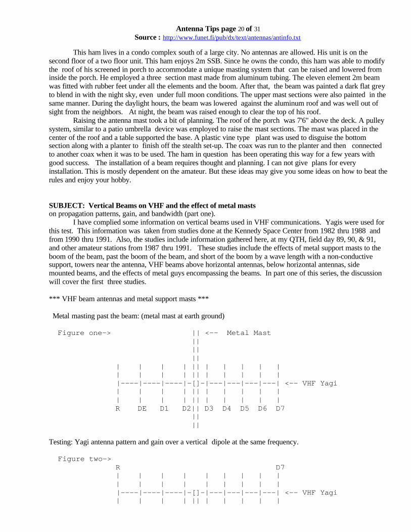
This ham lives in a condo complex south of a large city. No antennas are allowed. His unit is on thesecond floor of a two floor unit. This ham enjoys 2m SSB. Since he owns the condo, this ham was able to modifythe roof of his screened in porch to accommodate a unique masting system that can be raised and lowered frominside the porch. He employed a three section mast made from aluminum tubing. The eleven element 2m beamwas fitted with rubber feet under all the elements and the boom. After that, the beam was painted a dark flat greyto blend in with the night sky, even under full moon conditions. The upper mast sections were also painted in thesame manner. During the daylight hours, the beam was lowered against the aluminum roof and was well out ofsight from the neighbors. At night, the beam was raised enough to clear the top of his roof.
Raising the antenna mast took a bit of planning. The roof of the porch was 7'6" above the deck. A pulleysystem, similar to a patio umbrella device was employed to raise the mast sections. The mast was placed in thecenter of the roof and a table supported the base. A plastic vine type plant was used to disguise the bottomsection along with a planter to finish off the stealth set-up. The coax was run to the planter and then connectedto another coax when it was to be used. The ham in question has been operating this way for a few years withgood success. The installation of a beam requires thought and planning. I can not give plans for everyinstallation. This is mostly dependent on the amateur. But these ideas may give you some ideas on how to beat therules and enjoy your hobby.
SUBJECT: Vertical Beams on VHF and the effect of metal mastson propagation patterns, gain, and bandwidth (part one).
I have complied some information on vertical beams used in VHF communications. Yagis were used forthis test. This information was taken from studies done at the Kennedy Space Center from 1982 thru 1988 andfrom 1990 thru 1991. Also, the studies include information gathered here, at my QTH, field day 89, 90, & 91,and other amateur stations from 1987 thru 1991. These studies include the effects of metal support masts to theboom of the beam, past the boom of the beam, and short of the boom by a wave length with a non-conductivesupport, towers near the antenna, VHF beams above horizontal antennas, below horizontal antennas, sidemounted beams, and the effects of metal guys encompassing the beams. In part one of this series, the discussionwill cover the first three studies.
*** VHF beam antennas and metal support masts ***
Metal masting past the beam: (metal mast at earth ground)
Figure one-> || <-- Metal Mast || || || | | | | || | | | | | | | | | || | | | | | |----|----|----|-[]-|---|---|---|---| <-- VHF Yagi | | | | || | | | | | | | | | || | | | | | R DE D1 D2|| D3 D4 D5 D6 D7 || ||
Testing: Yagi antenna pattern and gain over a vertical dipole at the same frequency.
Figure two-> R D7 | | | | | | | | | | | | | | | | | | |----|----|----|-[]-|---|---|---|---| <-- VHF Yagi | | | | || | | | | |

Antenna Tips page 21 of 31Source : http://www.funet.fi/pub/dx/text/antennas/antinfo.txt
| | | | || | | | | | || || || <-- Metal Mast at earth ground
Testing: Same as in Figure one.
Figure three-> R D7 | | | | | | | | | | | | | | | | | | |----|----|----|-[]-|---|---|---|---| <-- VHF Yagi | | | | !! | | | | | | | | | !! | | | | | !! !! !! !! <-- Non-conductive mast (PVC) !! !! !! !! || || <-- Metal Mast at earth ground
Testing: Same as in Figure one.
Results of testing from test set-ups in figures one, two, and three:
1) Figure one results:• Pattern is mis-shaped, forward lobe is divided and severely distorted. Side lobes are enhanced, back
lobe is enhanced, but contains three distinctive lobes.• Gain over a vertical dipole is 2dB at the lowest central point of the forward lobes, gain is 3.7dB at the
highest points of the forward lobes which are at 59 and 124 degrees respectfully from a 90 degreecenter lobe location. Best gain is to the back center lob at 177 degrees, 5.3 dB.
2) Figure two results:• Pattern appears near normal with some distortion to the forward lobe.• Gain over a vertical dipole is 10.2dB at the peak of the central forward lobe which is located at 93
degrees.3) Figure three results:• Pattern shows near typical to standard patterns with better shaping than both previous tests.• Gain over a vertical dipole is 10.9dB at the peak of the central forward lobe which is located at 89.5
degrees.In each case, the same dipoles, coax, signal, and yagi were used for testing purposes. The distance
between the dipole and yagi was 100-ft. Height off the ground was 20-ft to the antenna feed. Signal was 10mW at146 MHz CW. Clearly, this test shows that mounting your yagi mid-mast is not an effective way to achieve thedesired results of the yagi. Mounting the beam on top of the mast achieves near commercial results while theinsulated mast achieves the best results for performance from the antenna. The discussion will continue, in parttwo, to elaborate on the effects of figure two vs figure three with a grounding wire. This test was conducted at theKennedy Space Center, Spring of 91 using the KB4YLY gamma modification to the yagi and dipoles. All testequipment used was by Hewlett-Packard. These tests were incorporated into antennas and antenna systems at theKennedy Space Center and are presented here for public information.
SUBJECT: Vertical Beams on VHF and the effect of metal masts on

Antenna Tips page 22 of 31Source : http://www.funet.fi/pub/dx/text/antennas/antinfo.txt
propagation patterns, gain, and bandwidth (part two).
TOWERS AND THEIR EFFECT ON VHF BEAMS
Towers have a dramatic effect on VHF beam patterns. Many hams mount their VHF beams on separatemasts or towers next to their main tower. Many hams also mount their VHF beams on arms extending from thetower. The tower poses an eclipsing effect on the VHF beam's pattern. The pattern is attenuated sharply by thetower, especially when the beam is pointed at the tower. This is fairly obvious. The attenuation is greater thecloser the beam is placed to the tower. This does not cover end mounted beams which actually use the tower ormast in their pattern. When a VHF beam is placed to the side of a tower, the area of the beam's forward lobemust be taken into consideration.
figure one: p p p p p p p T p p T T p p p p p p p X
In this example, the T's represent the tower, the X represents the beam, and the p's represent the edges of theforward lobe where the left p's are the right side and the right p's are the left side of the lobe. The area betweenthe edges, including the tower, is the high attenuation area. The angle formed by these edges is 60 degrees forthis example.
Figure two: p p p p T p T T P p p \ p p p p p p p p p p p pX \In this figure, the designators are the same as figure one. The beam's forward lobe is 60 degrees at the 3 dBpoints for this example. The minimum angle of the beam antenna, to directly pointing to the tower, is the sameas the 3 dB point beam width or 60 degrees. This means that the beam has a 120 degree angle, 60 degrees eitherside of the tower in relation to the beam, that is an attenuation or eclipse zone. It can be seen that the fartheraway the beam is from the tower the smaller the angle of attenuation is in relation to the beam. The asciirepresentation needs much improvement, but the point can be seen.
VHF BEAMS ABOVE AND BELOW HORIZONTAL HF BEAMS Normally, you should place the VHF beam approximately one wave length above any HF horizontal
with excellent results. Using the information from part one, best signal propagation can be obtained.

Antenna Tips page 23 of 31Source : http://www.funet.fi/pub/dx/text/antennas/antinfo.txt
Mounting the VHF beam below the HF horizontal beam can present problems relating to masting attenuation asstated in part one. A solution can be had though. By mounting the VHF beam offset to the mast and counterbalancing the arm with another VHF antenna or weight, you can mount the VHF antenna(s) below the HF beam.
figure three:
-----------------------[]-------------------- HF beam || || || mast || _______ || | o----------[]---------o| VHF beams on cross boom || | || |||| |||| tower
This is a head on view of the configuration discussed above. The only difficulties observed was the topheavyness of the HF beam on the extended mast (not recommended for high wind areas) and some difficulty onobtaining ducting for 2m/1.25m SSB operation. This is dependent on the proximity of the Horizontal VHF beamto the HF beam. This side mounting configuration rotates with HF beam and maintains a constant distance fromthe tower and HF beam.
METAL GUYS AND THEIR EFFECT ON VHF BEAMSThere is some effect on VHF beams and their proximity to metal guys. Most of the efect takes place
when the beam is mounted to the side of the tower enveloped by metal guys. The effect is not significant unlessthe beam is close the guys. If the VHF beam is on a rotor, make sure you have proper clearance for goodrotation. Having the last element snag on the guy will send you back up the tower for adjustments. This simplestep is often overlooked when installing a VHF beam in this way. Metal guys can be a serious disaster if theybecome entangled on the rotatable VHF beam. Take it from experience.
SUBJECT: Wire antennas - part oneDollar for dollar, the wire antenna is an Amateur Radio Operators best bet when it comes to inexpensive
antennas. In the lower bands, 160, 80, and 40m, the wire antenna is nearly the only means for most AROs towork those bands. Wire antennas perform from great to poor depending on many factors even when the antennais cut for the frequency desired. I'll discuss some of my findings with wire antennas in this eight part series. Sincemost of the wire antennas are published in numerous antenna books, the specifics of most wire antennas will beleft to the reader to investigate for the band they wish to operate in. Instead, I will discuss some helpful hints,findings, and misgivings about wire antennas that the ARO can use in overcoming the difficulties encounteredwith their first wire antennas and some that the old pros may find usefull. I will be discussing the advantages anddisadvantages of wire antennas on different bands, wire diameter, ground height, matching, multi-band wireantennas, and a few other odds and ends.
First, let's look at the capture area of a wire antenna cut as a dipole. We can examine this at 10m for easeof calculations and understanding. Many hams use a #12 or #10 wire when constructing their wire antennas. It'scheap and easy to obtain. Some wire antennas come as kits and use strained wire verses the solid conductor manyhams use in their home construction. Looking at the diameter of the wire, whether strained or not, it can be easilyseen that a dipole made from aluminum tubing has a greater capture area, without picking up a calculator to findout the difference. Larger diameter elements produce greater bandwidths, thus a wire dipole on 10m would havea limited bandwidth compared to it's aluminum tubing counterpart. How does one overcome this? Through trialand error, and a tight budget when I first got into Ham radio, I found that cutting the wire antenna slightly shorterthat the designed frequency and adding some tubing to the end of the dipole, I was able to expand the bandwidthof the wire antenna upto three times the orignal value. It doesn't take much tubing or a large diameter toaccomplish this. I used two of these units (of course, one on each end). There are two parts to the extention. Use
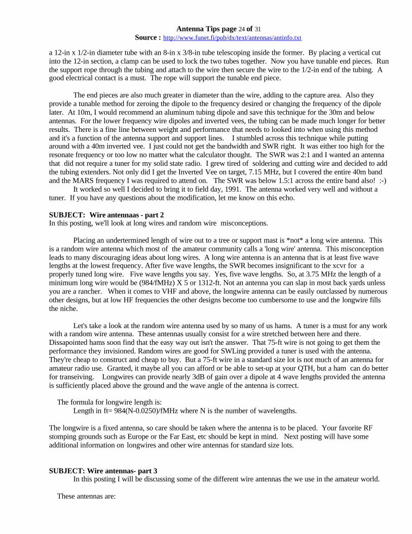
Antenna Tips page 24 of 31Source : http://www.funet.fi/pub/dx/text/antennas/antinfo.txt
a 12-in x 1/2-in diameter tube with an 8-in x 3/8-in tube telescoping inside the former. By placing a vertical cutinto the 12-in section, a clamp can be used to lock the two tubes together. Now you have tunable end pieces. Runthe support rope through the tubing and attach to the wire then secure the wire to the 1/2-in end of the tubing. Agood electrical contact is a must. The rope will support the tunable end piece.
The end pieces are also much greater in diameter than the wire, adding to the capture area. Also theyprovide a tunable method for zeroing the dipole to the frequency desired or changing the frequency of the dipolelater. At 10m, I would recommend an aluminum tubing dipole and save this technique for the 30m and belowantennas. For the lower frequency wire dipoles and inverted vees, the tubing can be made much longer for betterresults. There is a fine line between weight and performance that needs to looked into when using this methodand it's a function of the antenna support and support lines. I stumbled across this technique while puttingaround with a 40m inverted vee. I just could not get the bandwidth and SWR right. It was either too high for theresonate frequency or too low no matter what the calculator thought. The SWR was 2:1 and I wanted an antennathat did not require a tuner for my solid state radio. I grew tired of soldering and cutting wire and decided to addthe tubing extenders. Not only did I get the Inverted Vee on target, 7.15 MHz, but I covered the entire 40m bandand the MARS frequency I was required to attend on. The SWR was below 1.5:1 across the entire band also! :-)
It worked so well I decided to bring it to field day, 1991. The antenna worked very well and without atuner. If you have any questions about the modification, let me know on this echo.
SUBJECT: Wire antennaas - part 2In this posting, we'll look at long wires and random wire misconceptions.
Placing an undertermined length of wire out to a tree or support mast is *not* a long wire antenna. Thisis a random wire antenna which most of the amateur community calls a 'long wire' antenna. This misconceptionleads to many discouraging ideas about long wires. A long wire antenna is an antenna that is at least five wavelengths at the lowest frequency. After five wave lengths, the SWR becomes insignificant to the xcvr for aproperly tuned long wire. Five wave lengths you say. Yes, five wave lengths. So, at 3.75 MHz the length of aminimum long wire would be (984/fMHz) X 5 or 1312-ft. Not an antenna you can slap in most back yards unlessyou are a rancher. When it comes to VHF and above, the longwire antenna can be easily outclassed by numerousother designs, but at low HF frequencies the other designs become too cumbersome to use and the longwire fillsthe niche.
Let's take a look at the random wire antenna used by so many of us hams. A tuner is a must for any workwith a random wire antenna. These antennas usually consist for a wire stretched between here and there.Dissapointed hams soon find that the easy way out isn't the answer. That 75-ft wire is not going to get them theperformance they invisioned. Random wires are good for SWLing provided a tuner is used with the antenna.They're cheap to construct and cheap to buy. But a 75-ft wire in a standard size lot is not much of an antenna foramateur radio use. Granted, it maybe all you can afford or be able to set-up at your QTH, but a ham can do betterfor transeiving. Longwires can provide nearly 3dB of gain over a dipole at 4 wave lengths provided the antennais sufficiently placed above the ground and the wave angle of the antenna is correct.
The formula for longwire length is:Length in ft= 984(N-0.0250)/fMHz where N is the number of wavelengths.
The longwire is a fixed antenna, so care should be taken where the antenna is to be placed. Your favorite RFstomping grounds such as Europe or the Far East, etc should be kept in mind. Next posting will have someadditional information on longwires and other wire antennas for standard size lots.
SUBJECT: Wire antennas- part 3In this posting I will be discussing some of the different wire antennas the we use in the amateur world.
These antennas are:
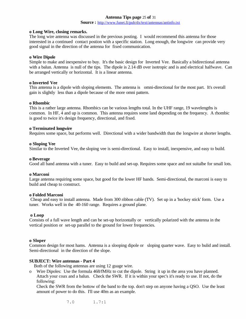
Antenna Tips page 25 of 31Source : http://www.funet.fi/pub/dx/text/antennas/antinfo.txt
o Long Wire, closing remarks.The long wire antenna was discussed in the previous posting. I would recommend this antenna for thoseinterested in a continued contact postion with a specific station. Long enough, the longwire can provide verygood signal in the direction of the antenna for fixed communication.
o Wire DipoleSimple to make and inexpensive to buy. It's the basic design for Inverted Vee. Basically a bidirectional antennawith a balun. Antenna is null of the tips. The dipole is 2.14 dB over isotropic and is and electrical halfwave. Canbe arranged vertically or horizontal. It is a linear antenna.
o Inverted VeeThis antenna is a dipole with sloping elements. The antenna is omni-directional for the most part. It's overallgain is slightly less than a dipole because of the more omni pattern.
o RhombicThis is a rather large antenna. Rhombics can be various lengths total. In the UHF range, 19 wavelengths iscommon. In HF, 4 and up is common. This antenna requires some land depending on the frequency. A rhombicis good to twice it's design frequency, directional, and fixed.
o Terminated longwireRequires some space, but performs well. Directional with a wider bandwidth than the longwire at shorter lengths.
o Sloping VeeSimilar to the Inverted Vee, the sloping vee is semi-directional. Easy to install, inexpensive, and easy to build.
o BeverageGood all band antenna with a tuner. Easy to build and set-up. Requires some space and not suitalbe for small lots.
o MarconiLarge antenna requiring some space, but good for the lower HF bands. Semi-directional, the marconi is easy tobuild and cheap to construct.
o Folded Marconi Cheap and easy to install antenna. Made from 300 ribbon cable (TV). Set up in a 'hockey stick' form. Use atuner. Works well in the 40-160 range. Requires a ground plane.
o LoopConsists of a full wave length and can be set-up horizontally or vertically polarized with the antenna in thevertical position or set-up parallel to the ground for lower frequencies.
o SloperCommon design for most hams. Antenna is a slooping dipole or sloping quarter wave. Easy to bulid and install.Semi-directional in the direction of the slope.
SUBJECT: Wire antennas - Part 4 Both of the following antennas are using 12 guage wire.ο Wire Dipoles: Use the formula 468/fMHz to cut the dipole. String it up in the area you have planned.
Attach your coax and a balun. Check the SWR. If it is within your spec's it's ready to use. If not, do thefollowing:Check the SWR from the bottow of the band to the top. don't step on anyone having a QSO. Use the leastamount of power to do this. I'll use 40m as an example.
7.0 1.7:1

Antenna Tips page 26 of 31Source : http://www.funet.fi/pub/dx/text/antennas/antinfo.txt
7.05 1.8:1 7.1 2.1:1 7.15 2.2:1 7.2 2.5:1 7.25 3.0:1 7.3 3.5:1
This indicates that the antenna is too long and the resonate frequency of the antenna is below the band. Thiscould happen because of the following:
ο A thicker diameter wire was used.ο You mis-measured.ο Something near the antenna is resonating with it.ο Too low to the ground.
Solution: trim off about six inches either side and try again.
ο Case two: SWR Readings;
7.0 4.0:1 7.05 3.5:1 7.1 3.3:1 7.15 3.0:1 7.2 2.4:1 7.25 2.0:1 7.3 1.8:1
This indicates the antenna is too short. "But I keep cutting off wire and it's still too short." (Raised eyebrows.)All is not lost here. Solution: add telescoping elements to the ends. Aluminum tubing, 3/8-in & 1/4-india.,secured with a screw should do the trick. 3/8-in dia. = 1-ft, 1/4-in dia. = 11-in in length.
__________________ wire attaches here =============__________________
Now you can adjust the ends of the dipole until the SWR reaches the desired level at the desired frequency. Thisproblem can happen when the guage of wire used is smaller than the recommended size.
Remember: Thicker => shorter; Thinner => longer.
Here's some Dipole measurements for HF:
BAND LENGTH-FT DESIGN FREQUENCY
10m 16' 5 1/2" 28.45 MHz 12m 18' 9" 24.94 MHz 15m 21' 11 1/4" 21.335 MHz 17m 25' 10" 18.11 MHz 20m 33' 0" 14.2 MHz 30m 46' 3" 10.12 MHz 40m 65' 5" 7.15 MHz 75m 123' 2" 3.8 MHz 80m 130' 0" 3.6 MHz 160m high 240' 0" 1.95 MHz 160m low 252' 10" 1.85 MHz

Antenna Tips page 27 of 31Source : http://www.funet.fi/pub/dx/text/antennas/antinfo.txt
SUBJECT: Wire antennas - part 5
RHOMBICSI've talked about rhombics before and in this posting I would like to discuss the rhombic for use in the
UHF range. We have hashed over rhombics in the HF range and many antenna books discuss this antennas.Most AROs don't have the room on their property or do not have property to construct a rhombic on. Thereseems to be very little on rhombics for UHF work.After looking at some plans for a multi-element rombic on 70cm, I decided to modify the plans and came up witha 23cm, 12 element rhomboid. The official name is a dual hexamerous rhomboid which is 2X6 rhomboid antenna.The antenna has twelve elements, with a gain of 33dBi, an is no bigger than a TV antenna! On 70cm, the antennais 19-ft long (apprx) and below that I wouldn't bother unless you have the tower and room. Unless you can mounta B-52 to a tower, 2m is out of the question.
Testing on the 23cm DHR shows a Front to back ratio greater than 30:1 with front to side ratios about thesame. This is a true cannon. The main lobe is tight at 12 degrees both vertical and horizontal. Matching is a bitdifficult since micro-strip knowledge is a must. Although the antenna is 50 ohms balanced, the frequencydemands exactness. This involves phasing elements, stripline baluns, and hardline feeds. But for the 23experimenter, this antenna packs the punch of a large parabolic reflector and in a small package. I'll be giving thedetails in the next posting.
SUBJECT: UHF RhombicIn wire antennas part 5 we discussed the UHF Rhombic antenna. I have the plans for one here. This
antenna is called the Dual Hexamerous Rhombiod or DHR. A stripline balun provides a 50 ohm output forinterface with hardline or antenna switch. The antenna consists of two stacked six element rhomboids. Each sixelement rhomboid consists of six rhombics of which each rhombic is 19 wave lengths and four sided. Eachrhombic is terminated at the 9.5 wave length mark with a *** 2w resistor. Each rhombic is geometricallyinterfaced to a wooden frame with a common start and ending point. Nineteen wave lengths was choosen for gainand front to back ratio. The actual plans for this antenna are available via the snail mail through me. Pleaseinclude a legal size envelope and one stamp. The BALUN is the key to the antenna and I would recommend thisfor those who are into 23cm and have stripline experience.
Folded MarconiThis is an easy antenna to construct and I recommend this highly for those AROs who have limited room
and desire an antenna that performs better than most wire antennas. The design is easy. Cut a length of 300 ohmribbon cable (TV line) using the following formula:
246/fMHz
ex: At 7.15MHz the Folded marconi length would be 246/7.15 or 34.4 feet.
Cut back about 1/2 inch and expose the leads in the ribbon cable. twist them together and solder. Seal with RTV.Punch a hole about one inch down from the soldered end and run a cable tie through the hole and save for later.
At the other end, expose about 3/4 inch of lead and solder one lead to the center conductor of your coax.The other lead is attached to a ground plane system or ... use the roof flashing on your house. You can ground theroof flashing and suspend the folded marconi over the house. This is the setup I have used here at the QTH. Theantenna was suspended over the house from my tower to the Palm tree in the front yard. The vertical height was25 feet and the rest was horizontal. With this antenna, the greater the vertical section the better. You will need atuner with this antenna as the impedance is very low.
SUBJECT: Wire antennas- part 7

Antenna Tips page 28 of 31Source : http://www.funet.fi/pub/dx/text/antennas/antinfo.txt
INVERTED VEEThis antenna is basically a half wave dipole with each leg sloped down at a 45 degree angle from the
horizontal, 180 degrees apart.
X feed point / | \ / | \ / | \ element leg / | \ / | \ | - tower or mast
----------X---------- Top view
The overall length of the Inverted Vee is slightly longer than the standard wire dipole. For 10m, the length is only2 inches longer. This antenna can be fed directly with 50 or 75 ohm coax, but it is suggested that a 1:1 BALUNbe used. The tips of the Inverted Vee should be kept well off the ground as the RF voltage levels are high at theends. This is more of a protection for young ones playing around the area.If you recall the formula c=sqrt(a^2 + b^2) and insert the length of the element leg for c. Use the fact that a = bbecause of the 45 degree angles between the mast and the element leg and the angle between the element leg andthe horizontal, this will equate to:
c = sqrt(2a^2) => a = sqrt(0.5c^2)
This will give you the value of a which is the height of the mast at the horizontal line to the end of the elementleg. Add eight feet for protection from the high RF voltage levels and you have the height of the mast required tosupport your Inverted Vee antenna. EX: 40m Inverted Vee; 66'2" @ 7.15 MHz (66'2")/2 = 33'1" c=33'1" => 33.0833 decimal
a = sqrt(0.5c^2) = 23.39345 => + 8 = 31.39345 => 31'4.75"
Thus the mast height is 31' 4.75" to support a 40m Inverted Vee, minimum.
The Inverted Vee is basically omni although the pattern is not quite but close enough. The gain is basically unityover a good ground. It is an inexpensive antenna to build and performs very well on all HF/MF bands.
BEVERAGE ANTENNAThis is also a basic wire antenna of which is one wave length or longer. Normal designs are one wave
and this must be kept in mind when placing one on the property. Once installed the direction is fixed. Thebeverage antenna has a low angle of propagation which makes it excellent for the lower bands (30m, 40m,75/80m, & 160m).
------------------------------- __ | | Rx }|{ Zo __}|{ | | G & radials G

Antenna Tips page 29 of 31Source : http://www.funet.fi/pub/dx/text/antennas/antinfo.txt
The Beverage is inefficient as a transmitting antenna and it is suggested that it be used as a receiving antennaonly. The pattern of the beverage is similar to a good yagi. Formulas and specifics for this antenna can be foundin the ARRL antenna handbook.
SUBJECT: Wire antennas- part 8
Sloping VeeThe Sloping Vee is basically an Inverted Vee in an equilateral triangle configuration at a 45 degree angle
to the vertical mast. Not as wideband as the inverted vee and also not omni as the antenna shows characteristicstowards the sloping elements. Basically unity + in gain. Can be fed with a 50 ohm coax but a 1:1 BALUN isrecommended. Element lengths are similar to the Inverted Vee design. This antenna is good for AROs withlimited space and stay within a specified area of a band. With a tuner the antenna will cover a wider range butwill be less effective. Remember that the same hold true for the Sloping Vee as the Inverted Vee; keep the endshigh enough off the ground so that children and adults can not touch them.
Terminated LongwiresSimilar to the Longwire, the terminated longwire is usually shorter and terminated with the characteristic
impeadance of the antenna. The terminating resistor should be able to handle at least half the intended powerlevels of the transceiver. This terminating resistor between 500 to 700 ohms when the antenna is 20 - 40 feetabove ground. Similar results can be obtained from the terminated longwire as with the Longwire as far asantenna patterns, directivity, etc.
Marconi AntennaThe marconi is a quarter wave antenna bent over to be parallel with the ground. This model works similar
to the Folded Marconi except ... this antenna requires a series LC circuit with the feed line connected to theinductor as a tap. Let'see how the ascii graphics can handle this.
--------------------------------------- / / Length = 125 for 160m / / | = tunable cap 700pF | }<---0-coax } L | L = 13 uH |----| X gound plane Well not too bad. Check out Orr & Cowan for the details.
Sloper.This antenna is great for the 'El Cheapo' antenna builders or the poor guy with no room. The antenna
consists of a quarterwave componet sloping down 45 degrees from the peak of the support and a grounding leadparallel to the support. The support itself can be used for the downlead provided it can conduct. The second formof the sloper is a dipole suspended 45 degrees down from the peak of the support. In either case, the antenna isdirective and the directivity is as such:
|\ feed point | \ sloper | \ | \ ---------> direction of wave | \ | \

Antenna Tips page 30 of 31Source : http://www.funet.fi/pub/dx/text/antennas/antinfo.txt
| \ | \ | | | mast | wooden support ----------------------------------------- ground
If you use a tree for the mast, be sure to clear the branches before the sloper actually starts. This is thefeed point and your down lead for the ground starts here also. If you look at it, it's nothing more than a dipolewith a vertical ground element and a sloping radiator. Like I promised (oh nooooo) here are some of the wiredesigns I have built here at the house. Some of these are the common mistake antennas that we all go through oryet to have, and maybe this will discourage some from making the same mistakes.
1) 80m Vee-Dipole: This one was a real hoser. I was a novice and decided that a wire antenna was the answerto all my dreams. With a tuner and this semi-correct design of mine I could work the world. Wrong. Here itis; one leg was 55'6" and the other was 65'0". The first leg was tied to a palm tree 25 feet off the ground. Thesecond leg was tied to another palm tree at 40 feet. Both legs combined at the monster tower (26 feet). So,the antenna legs pointed up instead of down and the angle between the legs was 85 degrees. Needless to sayit was a flop and the SWR was near the national debt.
2) 40/80m Trap Vee-Dipole: More or less the same results but I could tune in 80m now. It worked short rangevery well but 40m was dismal.
3) Folded Marconi: Worked absolutely wonderful until the first thunderstorm. I used fishing line to hold it up.The wind left it in my neighbors yard. Following Folded Marconi antennas were supported better and onlycame down when I wanted them to.
4) Coiled Marconi: Similar to the Folded Marconi, the Coiled Marconi uses a piece of four foot by 3/4 inchPVC:
@@@@@@@@@@@@@@@@@==|| Coiled section 20 turns / || / || / || |============|| Stand-off, 3 foot insulating \ || \ || \ || \ || X|| Feed point. || ||mast -------------------------
This antenna worked very well with a tuner and on 40m did not require a tuner at all. Cut the 300 ohmribbon cable (TV) to the same values as for a folded marconi.
5) 160m Spider Web Disaster: This was one of those 'Let's see what this old transformer winding wire can do'antennas. Although the antenna was pretty fair and I did talk to Tennessee, the antenna had a habbit ofcollecting odds and ends like palm frons, leaves, birds, branches, and these items caught the neighborhoodseye. "How is that branch hanging there?" "Is that bird hovering? My God he's dead!!" Needless to say, I tookit down and the bird too.
The last part of this series is going to be devoted to wire antennas used on past field days, including all the laughsand disappointments.
¥ Field Day 89, Draa Field, Titusville, FL. This was the field day of the Osprey. Draa field is a sharedfootball field by the two high schools in Titusville. It has 50 foot tall bleachers, press box, and six 70 foot highlighting towers made out of cement. They also make excellent homes for Ospreys and indeed the one tower we

Antenna Tips page 31 of 31Source : http://www.funet.fi/pub/dx/text/antennas/antinfo.txt
needed was home to a new family of Ospreys. These are no slouch birds mind you don't take kindly to having abrave amateur climb the rebar ladder under their babies. We had to draw straws but our best climber got the jobanyhow. What finally was placed up there was apulley system to raise our 80 inverted Vee. This did rather welland was worth the effort and much to the dive bombing and crying of the Ospreys. Too bad it rained the wholeweekend. |-( But we did do the best TARC ever did, 3700 points. Too bad the guy that was suppose to turn in thepoints never did.
¥ Field Day 88, Draa Field, Titusville, FL. On this field day we used two of the lighting towers and strungout a full wave loop for 80 meters. Well ... it wasn't quite high enough, and it wasn't in the right location, and itdidn't do well ... really poor ... it sucked ... and it rained all weekend.
¥ Field Day 90, Complex 25, Cape Canaveral Air Force Station. We had two wire antennas; a 40m InvertedVee taken from my tower here and using the mods I discussed earlier and a 'field day' 80m 'bow tie' antenna. The40m worked fine and we copped more than 500 points on 40m, but the 80m was dismal. And it rained allweekend.
¥ Field Day 91, Complex 25, Cape Canaveral Air Force Station. We dumped the bow tie and went with anInverted Vee for both 80 and 40. Too bad 80 was so so as we worked only 200 points worth. But we had noproblem reaching the Northeast and the Mississippi area. And it rained all weekend.
¥ Field Day 92, Complex 25, Cape Canaveral Air Force Station. We had beams on most bands but theInverted Vees worked fine again. This year we doubled our points and scored well in the 4000s working 4A. Nextyear they be a 40m yagi in operation. Look for K4FD, Kings 4 Field Day. BTW, it rained all day, ... again.
¥ Field Day 93: 10m 3e Yagi, 15m 3e Yagi, 20m 3e Yagi, 40m 2e Yagi, 80m Inverted Vee, SAT,PACKET, see you on the air, I'll be on 20m.