winwarbler help - kambing.ui.ac.idkambing.ui.ac.id/onnopurbo/orari-diklat/teknik/dx/...automatically...
TRANSCRIPT

WinWarbler Help WinWarbler helps you conduct QSOs in the CW, Phone, PSK31, PSK63, and RTTY modes. The topics below will introduce you to its capabilities in-depth; for a quick tour, you can review the PSK screen capture and RTTY screen capture. If you let the mouse cursor dwell over a control for a few seconds, WinWarbler will pop up an tooltip explaining that control's function; the display of tooltips can be disabled once you've become familiar with the program. WinWarbler is free, and contains no advertising. Commercial use is expressly forbidden. Prerequisites Downloading and Installation Configuration
• General Settings • Display Settings • Push-to-talk (PTT) settings • Soundcard PSK settings • Soundcard PSK Broadband Decode
settings • Defining PSK sub-bands • CW settings • Phone settings • Soundcard RTTY settings • Defining RTTY sub-bands • External RTTY Modem settings • External RTTY Modem command files • Soundcard settings • Configuring multiple soundcards
Logging
• Overview • the Minilog • Capturing Information from Decoded Data • Information Logged • Keyboard Shortcuts
Macros Position & Vector
CW • Setup and interfacing • Operation • Keystrokes and the CW they generate • Options
Phone
• Setup and interfacing • Operation • Options
PSK31 and PSK63
• Annotated main window capture • Reception • Transmission • Broadband Decode • Configuration
RTTY
• Annotated main window capture • via Soundcard
o Reception o Transmission o Configuration
• via external modem o Reception o Transmission o Configuration o Modem command files

WinWarbler 4.4.4 2
WinWarbler Prerequisites To use WinWarbler, you need
• a PC running Windows 95, Windows 98, Windows 2000, Windows XP, or Windows NT, ideally o 75 MHz Pentium or better o 32 MB RAM or better
• a SoundBlaster-compatible sound card and drivers • an SVGA display or better • a transceiver covering the frequencies of interest • appropriate connections between your sound card and transceiver inputs and outputs
The VOX circuits of some transceivers can be configured to automatically trigger when WinWarbler transmits. Alternatively, you can appropriately connect a free com port to your transceiver's PTT circuit to automatically place your transceiver in transmit mode. In RTTY mode, WinWarbler can decode a second frequency (or provide diversity decoding of a single frequency) if an external RTTY modem such as a KAM or PK232 is available and appropriately configured. External modems like the SCS PTC family that support modes like Amtor and Pactor are also supported.

WinWarbler 4.4.4 3
WinWarbler Download and Installation Step Directions 1 Create the application folder in which WinWarbler will reside, such as:
C:\Program Files\WinWarbler 2 In the application folder, create an installation subfolder in which the downloaded and
extracted files will reside, such as: C:\Program Files\WinWarbler\Install
3 Go to http://www.qsl.net/winwarbler/WinWarbler300Archive.exe to download
WinWarbler300Archive.exe, a 4.9 MB self-extracting executable file that contains WinWarbler and its associated files. When prompted, direct your browser to store this file into the installation subfolder you created in step 2.
4 Run WinWarbler300Archive.exe - in its WinZip Self-Extractor dialog box, direct it to place
the unzipped files into the installation subfolder you created in step 2, and click the Unzip button. After extraction completes, click the Close button. The following files should now be present in the installation subfolder:
• WinWarbler300Archive.exe • WinWar1.cab • WinWar2.cab • WinWar3.cab • WinWar4.cab • setup.exe • Setup.lst
5 To install WinWarbler, run the setup.exe program in the installation subfolder. Ignoring the
setup program's request to close all running applications may result in error messages during the installation process, and possibly a faulty installation. After copying several system files, the setup program may ask that you reboot your PC before continuing with the setup. If, after rebooting, your PC does not run setup.exe on its own, direct it to do so. The setup program may report that the files being installed are older than files already installed on your system, and ask whether you want to over-write the existing newer files with the older files -- you should decline.
6 To execute WinWarbler, run the program WinWarbler.exe in the application folder. 7 After WinWarbler is installed and you've verified that it works, you may delete the
installation subfolder and the files it contains. 8 Check http://www.qsl.net/dxlab/download.htm for access to the latest development release
You can uninstall WinWarbler by running the Add/Remove Programs applet on the Windows control panel. If you have questions or suggestions, please post them on the DXLab reflector; at http://groups.yahoo.com/group/dxlab/ . If you're not a member, you can sign up at http://www.qsl.net/dxlab/reflector.htm.

WinWarbler 4.4.4 4
WinWarbler Configuration The first time you run WinWarbler, you will be asked to enter your callsign. Once this has been completed, WinWarbler is ready for basic PSK31. PSK63, and Soundcard RTTY operation. Basic controls -- such as those that start/stop transmission, enable/disable Automatic Frequency Control (AFC), enable/disable NET operation, or log a QSO -- are located on WinWarbler's main window. Clicking the Config button on WinWarbler's main window displays a tabbed dialog box that provides additional control of WinWarbler's behavior and appearance. Panels on the Configuration window's General tab let you
• change your callsign • enable automatic archiving of the information WinWarbler receives and transmits • specify the initialization and behavior of items used in logging • tune WinWarbler to support contesting • align WinWarbler's frequency readout with your transceiver's during RTTY operation • display the Position and Vector Configuration window, from which you can
o specify values for your current latitude, longitude, grid square, course, and speed o enable connection to a NMEA-compliant Global Positioning Satellites (GPS) receiver that
automatically updates your current latitude, longitude, grid square, course, and speed, and determine the number of satellites contributing to the position computation
o specify the serial port to which a GPS receiver is connected • choose the browser that displays WinWarbler's online help
Panels on the Configuration window's Display tab enable you to
• select the colors and font styles of transmitted and received text displayed in each receive pane • select the colors and font styles of text displayed in the transmit pane • select the trace color used in spectrum, vector, and XY tuning displays
Panels on the Configuration window's Push-to-talk (PTT) tab let you determine whether and how WinWarbler directs your transceiver to switch between receive and transmit modes. Panels on the Configuration window's PSK tab PSK31 and PSK63 reception and transmission, and Settings in this panel allow you to
• choose BPSK USB, BPSK LSB, QPSK USB, or QPSK LSB modulation (note that QPSK modulation is used with PSK31, but not with PSK63)
• set limits for search range and AFC tracking • choose between waterfall and spectrum tuning displays • set the squelch speed • specify an optimal audio offset, permitting one-click QSY to place the currently-received signal in your
transceiver's passband • select the speed at which CW identification is sent • compensate for a frequency offset between your transmitter and receiver • compensate for error in your soundcard's clock rate
Panels on the Configuration window's Soundcard tab let you choose a soundcard for PSK operation if your PC has more than one, and provide a means to invoke the Windows multimedia mixer, whose controls governing the levels of signals received and transmitted via the selected soundcard Panels on the Configurations window's Broadband Decode tab provide control over a mechanism that can simultaneously decode and monitor up to 47 PSK signals between 100 hz and 3500 hz.

WinWarbler 4.4.4 5
Panels on the Configuration window's RTTY tab let you • enable or disable Soundcard RTTY operation • specify baud rate • specify shift • enable or disable Unshift On Space (USOS) • enable or disable reverse RTTY • specify whether your transmitter is using AFSK or FSK • specify whether characters should be sent immediately after their entry, or only after a word has been
entered • choose between waterfall and spectrum tuning displays • tune the RTTY engine's demodulator
Panels on the Configuration window's External Modem tab enable you to
• specify the specific RTTY modem in use and the serial port to which its connected • enable or disable Soundcard RTTY operation • specify baud rate • specify shift • enable or disable Unshift On Space (USOS) • enable or disable reverse RTTY • specify whether your transmitter is using AFSK or FSK
Panels on the Configuration window's CW tab enable you to
• specify the transceiver mode to be used when CW operation is selected • compensate for a transceiver offset during CW operation • specify whether characters should be displayed as they are transmitted • specify the keyboard mode (auto start, auto stop, send each character or accumulate a word before
sending) • specify keying mode (transceiver control software, serial port modem control signal, PTT port modem
control signal, external modem, WinKey) • specify PTT parameters (enable/disable, lead time, lag time) • specify CW weight • specify WinKey parameters
Panels on the Configuration window's Phone tab enable you to
• specify the transceiver mode to be used when Phone operation is selected • compensate for a transceiver offset during Phone operation • specify whether PTT is enabled during Phone operation
External RTTY modem commands are specified in files located in WinWarbler's Modems subfolder. WinWarbler includes files for the KAM and PK232. You can modify these files, or create files for other RTTY modem models using a simple command syntax.

WinWarbler 4.4.4 6
WinWarbler General Settings The General tab of WinWarbler's Configuration window contains 6 panels, each containing a related group of settings that you can inspect and/or modify. This window also provides four buttons along its bottom border:
• Display Error Log - displays the file Errorlog.txt in WinWarbler's folder, which contains diagnostic and error recovery information
• Position and Vector - displays the Position and Vector Configuration window for use with a GPS receiver • About - displays a window that shows the versions of PSKCORE and MMTTY currently in use • Help - displays this online documentation
General Panel
operator the operator's callsign • appears in the main window title bar • appears in the OPERATOR field of each log record • is inserted into macros via the <mycall> command
show control explanations
when checked, enables the display of explanatory information when the mouse cursor lingers over a textbox, button, checkbox, display pane, or setting.
show 0 as Ø when checked, displays the character 0 (zero) as Ø in receive panes. waterfall right-click • when unchecked, right-clicking in the waterfall sets the transmit
frequency and CTRL-right clicking invokes the optimal offset function • when checked, right-clicking in the waterfall invokes the optimal offset
function and CTRL-right clicking sets the transmit frequency automatic lookup when checked, DXKeeper, is directed to produce a filtered display showing
previous QSOs with that callsign and perform a callbook lookup (if installed) when
• Double-clicking on a received callsign • striking the enter key in the callsign textbox
automatic archiving when checked, information presented on each pane is continuously appended to a separate file located in WinWarbler's AutoArchive subfolder
automatic archiving timestamp
when checked with automatic archiving enabled, records a timestamp in each active pane's archive file every 5 minutes
clear QSO Info on callsign capture
if checked, items in the QSO Info field will be cleared when a new callsign is entered, or when the Enter or Tab keys are struck while focus resides in the callsign item
set QSO Start when RST received
when checked, the QSO will be deemed to have started and its Start Time will be captured when the rst R textbox is modified
initialize RST items to 59/599
when checked, the rst S and rst R textboxes will, if empty, be set to 599 (or 59 if the Mode is Phone) when you strike Enter or double-click in the Call textbox or when you double-click on a callsign in a receive pane
highlight PSK RTTY sub-bands
when checked, highlight PSK sub-bands and RTTY sub-bands in the tuning display's frequency scale by displaying frequencies and tick marks in green
preset QSL checkbox
when checked, the QSL box is initialized to checked
prompt on QSO Info overwrite
when checked, if an action -- e.g. double-clicking on a SpotCollector spot database entry -- would overwrite unsaved QSO Info panel data from a QSO that has started, WinWarbler will display a dialog box allowing the user to allow or disallow the overwrite

WinWarbler 4.4.4 7
use dual monitors when checked, windows that appeared on the secondary monitor during the previous session will be restored to the secondary monitor at startup
log debugging information
when checked, writes diagnostic information to the file errorlog.txt in WinWarbler's folder
Log Panel
flag invalid callsigns
when checked, callsigns that doesn't contain at least one number and one label are flagged as invalid when logging is attempted
require DXCC when checked, prevents the logging of QSOs for which no DXCC item has been selected unless the callsign is a mobile or begins with an exclamation point
export for DXbase when checked, WinWarbler records frequencies in a format compatible with the DXbase logging program
default QSL msg default QSL message used to initialize the QSO Info panel's QSL msg textbox when the Enter or Tab key is struck in the QSL Info panel's call textbox
default Tx Pwr default QSL message used to initialize the QSO Info panel's TX Pwr textbox when the Enter or Tab key is struck in the QSL Info panel's call textbox
Clear Minilog clicking this button deletes the Minilog file Contesting Panel
contest mode when checked, WinWarbler • moves the cursor focus to the RX# textbox after you strike Enter in the
QSO Info panel's call textbox • records 59/599 in the rst S and rst R items of each log record • when you double-click on a sequence of digits in a receive pane, copies
that sequence into the RX# textbox • when you double-click on a word in a receive pane while simultaneously
depressing the ALTand CTRL keys, copies that word to the RX# textbox• when you selecting a group of contiguous words in a receive pane while
simultaneously depressing the ALT and CTRL keys, copies those words to the RX# textbox
• if the increment TX# setting is enabled, increments the contents of the TX# setting when the Log button is clicked, or when the <advance_tx_serial_number> macro substitution command is executed
• if DXKeeper is running and configured to perform previous QSO lookups, flags duplicate QSOs with the word Dup! to the left of the QSO Info panel's call textbox
• moves the cursor focus to the QSO Info panel's call textbox after any action that clears the QSO Info panel
• displays the word "Contest" followed by the default contest name in the Main window's title bar; if no default contest name is specified, displays "Contest: ?"
Note: when you first start a contest, be sure to initialize TX#; clicking the Reset TX Serial# button will set TX# to 1.
contest if contest mode is checked, the contents of this default contest name setting are used to initialize the QSO Info panel's Contest textbox when the Enter or Tab key is struck in the QSL Info panel's call textbox
TX# the transmit serial number that will be logged with the next QSO (need not be numeric)
X clicking this button sets TX# to 1

WinWarbler 4.4.4 8
increment TX# when checked, the transmit serial number is incremented (if its numeric) after each QSO is logged
place focus in RX# on DX Spot activation
when checked, places focus in the QSO Info panel's RX# item when a DX spot is activated in SpotCollector, DXView, or Commander
don't log contest, TX#, or RX# if contest mode is disabled
when checked while not it contest mode, disable the Contest, TX#, and RX# textboxes in the QSO Info panel, and logs the ADIF Contest, STX, and SRX items as empty strings
Audio Frequency Markers Panel
frequency 1 frequency (hz) of the red marker on the waterfall or spectrum display's frequency scale; double-clicking this setting clears it, suppressing display of the red marker
frequency 2 frequency (hz) of the blue marker on the waterfall or spectrum display's frequency scale; double-clicking this setting clears it, suppressing display of the blue marker
Preset Frequencies Panel This panel lets you specify up to eight preset frequencies for selection via the QSO Info panel's Freq selector. Help Browser Panel
browser pathname if this setting is blank, WinWarbler displays online help using your PC's default HTML browser; if this setting contains the pathname of an HTML browser, WinWarbler displays online help using that browser.

WinWarbler 4.4.4 9
WinWarbler Display Settings The Display tab of WinWarbler's Configuration screen contains panels that control the appearance of received text, transmitted text, and the Spectrum, Vector, and XY displays.

WinWarbler 4.4.4 10
Receive Pane Display Settings The following settings are provided in panels for each of the three receive panes:
Font Color clicking this button displays a color selector that lets you choose the color of the pane's received text; this same color is displayed on the identification panel to the left of each receive pane, and identifies the associated channel's waterfall trace
Back Color clicking this button displays a color selector that lets you choose the color of the receive pane's background color
Font Name displays the name of the font used to display text appearing in the receive pane; clicking this control displays a standard Windows font selector, allowing you to choose any available font, specify its point size, and specify whether it is to be rendered in bold and/or italics
Font Size this slider displays and controls the point size of text appearing in the receive pane
Changing font characteristics can make a pane's existing text unreadable; thus such modifications should be avoided while in QSO. The Transmitted Text setting controls the color of transmitted text in all three receive panes:
Font Color clicking this button displays a color selector that lets you choose the color of transmitted text
When a receive channel is selected, the label to the left of its pane (on WinWarbler's main screen) is given a unique color; The Selected Channel setting specifies this color. Since each channel label appears over a panel whose color matches the font color of its associated receive pane, choose a color for the selected channel label that contrasts with all three receive pane font colors.
Label Color clicking this button displays a color selector that lets you choose the color of the channel label for the currently-selected receive pane
The Optimize tuning display for panel determines whether Monitor Channel markers will be shown against a white background and tuning display trace borders will be rendered in black, or Monitor Channel markers will be shown against a black background and tuning display trace borders will be rendered in white. If you select light receive pane font colors and dark receive pane background colors, then you should chose Light marker or trace colors on a dark background and select a light Monitor Channel marker color (e.g. white) . If you select dark receive pane font colors and light receive pane background colors, then you should chose Dark marker or trace colors on a light background and select a dark Monitor Channel marker color (e.g. black) . Changes made to the above settings are immediately applied, so you can assess your customization by direct observation. To reduce the need for flipping between windows on systems with smaller screen sizes, each panel contains a preview textbox illustrating the appearance of both received text (on the left) and transmitted text (on the right).

WinWarbler 4.4.4 11
Transmit Pane Display Settings The following settings are provided for the transmit pane:
Font Color clicking this button displays a color selector that lets you choose the color of keyboard-generated or macro-generated text
Back Color clicking this button displays a color selector that lets you choose the transmit pane's background color
Font Name displays the name of the font used to display text appearing in the transmit pane; clicking this control displays a standard Windows font selector, allowing you to choose any available font, specify its point size, and specify whether it is to be rendered in bold and/or italics
Font Size this slider displays and controls the point size of text appearing in the transmit pane; the transmit pane's height is automatically scaled to properly display the selected font size
Spectrum Display, Vector, and XY Display Settings
Trace Color clicking this button displays a color selector that lets you choose the color of the trace used to render the spectrum display, vector, and XY display
Monitor Channel settings
Marker Color clicking this button displays a color selector that lets you choose the color of the markers used to designate the frequency of each locked monitor channel
Set Default Colors button Clicking this button sets all colors to reasonable default values. If incoming text is not visible because font colors and background colors lack sufficient contrast, this function will rectify the situation.

WinWarbler 4.4.4 12
WinWarbler Push-to-talk (PTT) Settings The PTT tab of WinWarbler's Configuration screen contains two panels that indicate how the transceiver is to be switched between transmit and receive modes.
When Soundcard RTTY is active, the specified PTT port is used by the MMTTY engine for PTT (if the PTT Mode is set to RTS+DTR) and/or FSK (if the Soundcard RTTY modulation and transceiver mode panel is set to FSK (USB) or FSK (LSB).

WinWarbler 4.4.4 13
PTT Mode panel none the transceiver must be manually switched between receive and transmit modes,
or utilize VOX RTS the RequestToSend modem control signal is asserted on the PTT port when
transmitting; this choice is not available when Soundcard RTTY is active. DTR the DataTerminalReady modem control signal is asserted on the PTT port when
transmitting; this choice is not available when Soundcard RTTY is active. RTS+DTR both the RequestToSend and DataTerminalReady modem control signals are
asserted on the PTT port when transmitting except when operating CW: • if CW keying is set to use the PTT port's RTS signal, then only DTR will
be used for PTT during CW transmission • if CW keying is set to use the PTT port's DTR signal, then only RTS will
be used for PTT during CW transmission Xcvr Ctrl SW inter-application messages are sent to Commander, directing it to switch the
transceiver between receive and transmit modes PTT port panel This panel's caption indicates how the selected port is being used:
none the selected port is not being used PTT the select port's modem control signals are being used to effect transmit/receive
switching MMTTY FSK the selected port's TxD signal is being used by the MMTTY engine to convey
FSK data MMTTY PTT & FSK
the select port's modem control signals are being used to effect transmit/receive switching, and its TxD signal is being used by the MMTTY engine to convey FSK data
The panel lets you select the serial port used for transmit/receive switching and/or Soundcard RTTY FSK:
none no serial port is used for transmit/receive switching and/or Soundcard RTTY FSK com1-8 asserts modem control signals on the selected PC serial communications port, as
specified by the PTT mode setting; if Soundcard RTTY is enabled and FSK mode is selected, FSK data is conveyed via port 1's TxD pin
com9-16 asserts modem control signals on the selected PC serial communications, as specified by the PTT mode setting (can not be used for soundcard RTTY operation)

WinWarbler 4.4.4 14
WinWarbler PSK Settings The PSK tab of WinWarbler's Configuration window contains four panels that control PSK31 and PSK63 mode operation. (screen capture)
• Receiver panel • Transmitter panel • Transceiver panel • Soundcard clock adjust panel
The frequency scale above the tuning display is rendered in green for frequencies within PSK sub-bands, and in red for frequencies outside of PSK sub-bands; you can customize the definition of these sub-bands by copying and editing a file. The Receiver panel contains 5 sub-panels, each containing a related group of settings that you can inspect and/or modify.
WinWarbler 4.4.4 15
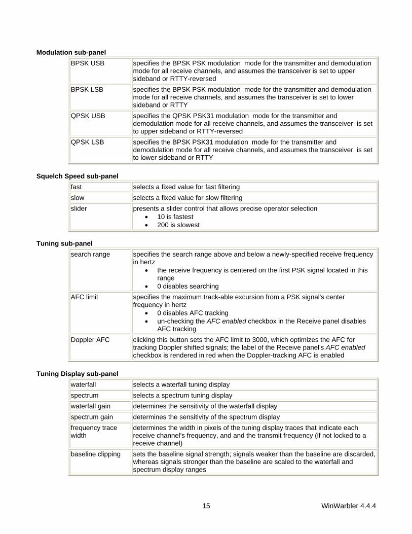
Modulation sub-panel BPSK USB specifies the BPSK PSK modulation mode for the transmitter and demodulation
mode for all receive channels, and assumes the transceiver is set to upper sideband or RTTY-reversed
BPSK LSB specifies the BPSK PSK modulation mode for the transmitter and demodulation mode for all receive channels, and assumes the transceiver is set to lower sideband or RTTY
QPSK USB specifies the QPSK PSK31 modulation mode for the transmitter and demodulation mode for all receive channels, and assumes the transceiver is set to upper sideband or RTTY-reversed
QPSK LSB specifies the BPSK PSK31 modulation mode for the transmitter and demodulation mode for all receive channels, and assumes the transceiver is set to lower sideband or RTTY
Squelch Speed sub-panel
fast selects a fixed value for fast filtering slow selects a fixed value for slow filtering slider presents a slider control that allows precise operator selection
• 10 is fastest • 200 is slowest
Tuning sub-panel
search range specifies the search range above and below a newly-specified receive frequency in hertz
• the receive frequency is centered on the first PSK signal located in this range
• 0 disables searching AFC limit specifies the maximum track-able excursion from a PSK signal's center
frequency in hertz • 0 disables AFC tracking • un-checking the AFC enabled checkbox in the Receive panel disables
AFC tracking Doppler AFC clicking this button sets the AFC limit to 3000, which optimizes the AFC for
tracking Doppler shifted signals; the label of the Receive panel's AFC enabled checkbox is rendered in red when the Doppler-tracking AFC is enabled
Tuning Display sub-panel
waterfall selects a waterfall tuning display spectrum selects a spectrum tuning display waterfall gain determines the sensitivity of the waterfall display spectrum gain determines the sensitivity of the spectrum display frequency trace width
determines the width in pixels of the tuning display traces that indicate each receive channel's frequency, and and the transmit frequency (if not locked to a receive channel)
baseline clipping sets the baseline signal strength; signals weaker than the baseline are discarded, whereas signals stronger than the baseline are scaled to the waterfall and spectrum display ranges

WinWarbler 4.4.4 16
FFT averaging specifies the degree of averaging using during Fast Fourier Transform (FFT) processing
• 1 = no averaging • 10 = maximum averaging
waterfall display specified the colors used in the waterfall display • mono - monochrome • synthetic - false color, using a color lookup table devised by AE4JY
channel ID determines how receive channel and transmit frequencies are indicated on the waterfall and spectrum displays
• traces -via colored lines; in the waterfall display, the width of these lines is set by the frequency trace width slider
• markers - via colored triangles above the tuning display; the width of these lines indicates the bandwidth of the current mode's signals
Optimal Offset sub-panel The textbox in this panel allows you to specify the optimal receive offset frequency, in Hz., used by the Optimize Offset function. Values must lie in the range of 50 to 3500. The Transmitter panel contains 5 sub-panels, each containing a related group of settings that you can inspect and/or modify. Modulation sub-panel
BPSK USB specifies the BPSK PSK modulation mode for the transmitter and demodulation mode for all receive channels, and assumes the transceiver is set to upper sideband or RTTY-reversed
BPSK LSB specifies the BPSK PSK modulation mode for the transmitter and demodulation mode for all receive channels, and assumes the transceiver is set to lower sideband or RTTY
QPSK USB specifies the QPSK PSK31 modulation mode for the transmitter and demodulation mode for all receive channels, and assumes the transceiver is set to upper sideband or RTTY-reversed
QPSK LSB specifies the QPSK PSK31 modulation mode for the transmitter and demodulation mode for all receive channels, and assumes the transceiver is set to lower sideband or RTTY
Tune transmit a steady carrier for tuning Tune/ID transmit a steady carrier for tuning and send a CW identification when
transmission is complete CW ID Speed sub-panel
9 wpm if PSK31 mode, transmits the CW identification string at the rate of 9 words per minute; if in PSK63 mode, 19 words per minute
12 wpm if PSK31 mode, transmits the CW identification string at the rate of 12 words per minute; if in PSK63 mode, 19 words per minute
19 wpm transmits the CW identification string at the rate of 19 words per minute 37 wpm transmits the CW identification string at the rate of 37 words per minute

WinWarbler 4.4.4 17
RX-TX Offset sub-panel This setting can be used to compensate for a frequency offset between transmitter and receiver. Specify your transmitter's offset in Hz. If your transmitter's frequency is 10hz higher than your receiver's frequency, enter 10; if it's 10 hz lower, enter -10).
CW ID String sub-panel CW identification string
specifies the information sent in Morse code when the CWID button in the Transmit panel is clicked, or when the transmission modulation setting is Tune/ID
• * (asterisk) generates the SK prosign • + (plus sign) generates the AR prosign • = (equal sign) generates the BT prosign
The Transceiver panel The Transceiver Mode subpanel enables you to specify the mode to which the transceiver is set (if Commander is running) during PSK operation.
SSB if the Transmitter Modulation is set to LSB, then set the transceiver to LSB; otherwise set the transmitter to USB
RTTY set the transceiver to RTTY RTTY-R set the transceiver to RTTY-R PKT set the transceiver to PKT
The PSK Offset subpanel lets you specify an offset (Hz) that aligns the displayed PSK receive frequency with a known PSK frequency; negative values are accepted. This can be used to compensate for an offset between your transceiver's VFO display and its actual frequency. The Soundcard clock adjust panel enables you compensate for a soundcard clock frequency that's fast or slow by up to10,000 parts-per-million (PPM); The free application MMSSTV includes an excellent soundcard calibration mechanism that displays your soundcard's error in PPM; be sure to configure MMSSTV for a clock frequency of 48 khz, which is what WinWarbler's PSK engine uses. Defining custom PSK sub-bands If sub-band highlighting is enabled, the frequency scale above the tuning display is rendered in green for frequencies within PSK sub-bands, and in red for frequencies outside of PSK sub-bands. By default, PSK sub-bands are defined by the contents of the file DefaultPSKBands.txt in WinWarbler's Databases folder. Each line in this file defines the PSK sub-band within a named band: 160M, 1.807, 1.811 80M, 3.580, 3.584 40M, 7.070, 7.074 30M, 10.140, 10.144 20M, 14.070, 14.074 17M, 18.100, 18.110 15M, 21.070, 21.074 12M, 24.920, 24.930 10M, 28.120, 28.124 To specify your own sub-bands, make a copy of DefaultPSKBands.txt in the Databases folder and name it PSKBands.txt. Edit the frequencies in PSKBands.txt as desired, and save your changes; you can also define sub-bands for the 6M and 2M bands. In the Main window's Mode panel, select a mode other than PSK or PSK63, and then select PSK or PSK63. the tuning display's frequency scale will be colored as specified by your custom sub-band definitions.

WinWarbler 4.4.4 18
WinWarbler Soundcard PSK Broadband Decode Settings The PSK Broadband Decode tab of WinWarbler's Configuration window provides control over a mechanism that can simultaneously decode and monitor up to 47 signals whose audio tones fall in the range of 100 Hz. to 3500 Hz.
When the enable box is checked, WinWarbler deploys 47 monitor channels across the audio band from 100 hertz to 3500 hertz; each monitor channel thus covers approximately 72 hertz of spectrum. Signals that meet the decoding criteria specified below can be optionally denoted by channel markers: triangles on a black bar or white bar above the tuning display as specified by the Optimize tuning display panel setting. Channel markers appear if the Channel Monitor is enabled or if the Channel Monitor's always show monitor channel markers box is checked. Decoded callsigns are displayed in the Stations Heard window.

WinWarbler 4.4.4 19
When the Channel Monitor panel's enable box is checked, WinWarbler displays a Channel Monitor window that displays the following information for each monitor channel:
• frequency • signal quality • signal strength • receiving_callsign • transmitting_callsign • decoded text (this text either scrolls left to right or is painted right to left as specified by the decoded text
panel setting) The AFC control specifies the maximum track-able excursion from a PSK signal's center frequency in hertz for each monitor channel. 0 disables AFC; the maximum value is 1000 hertz. Half the monitor channel range -- 36 hertz -- is a good starting value for this setting. The Squelch panel provides controls that set the squelch level and speed for all monitor channels. If an incoming signal's quality is below that of the specified squelch level, characters are not decoded. The minimum value 0 disables all squelch action, whereas the maximum value of 99 disables all decoding. A squelch level of 25 with fast action is a reasonable initial setting. The Decoding Triggers panel provides settings that determine whether a monitored channel is considered to be tracking a viable PSK signal. WinWarbler checks each monitor channel's signal quality every 200 ms and assigns it a state. Initially, each monitor channel's state is unlocked. If a monitor channel's signal quality exceeds the squelch level, a counter is incremented, and that monitor channel is considered to be locking; if the signal quality falls below the squelch level, the counter is zeroed, and the monitor channel is considered to be unlocked. If the counter reaches the value specified in the Start setting, the monitor channel is considered locked, which enables the subsequent extraction of callsign information from the decoded text. WinWarbler continues to sample a locked monitor channel's signal quality every 200 ms. If the signal quality falls below the squelch level, a counter is incremented and the monitor channels is considered to be unlocking. If the signal quality subsequently exceeds the squelch level, the counter is zeroed and the channel is again considered locked. If the counter reaches the value specified in the Stop setting, the monitor channel is considered unlocked, and callsign extraction is discontinued. Each monitor channel is managed individually through the four states: unlocked, locking, locked, and unlocking. The state of each monitor channel is indicated by the color of the font used to render its channel number in the Channel Monitor window:
State Channel # Font Color Unlocked black Locking magenta Locked red Unlocking blue
The QSO Inactivity Timeout determines how long a monitor channel can remain unlocked before its captured callsign information is discarded. Since WinWarbler may only be monitoring one side of a QSO, 2 minutes is a reasonable value for this setting.

WinWarbler 4.4.4 20
The Stations Heard panel provides setting that govern the list of transmitting stations displayed in the Stations Heard window, as well as a Display Stations Heard button that when clicked displays the Stations Heard window.
Setting Effect
delete calls heard only once at age
If a Station Heard list entry's transmitting callsign has been decoded only once, delete the entry after the specified number of minutes elapse without decoding the callsign again (default is 2 minutes)
delete calls heard more than once at age
If a Station Heard list entry's transmitting callsign has been decoded more than once, delete the entry after the specified number of minutes elapse without decoding the callsign again (default is 15 minutes)
font size specified the font size used to display entries in the Stations Heard list
display quality and strength when checked, each entry in the Station Heard list includes the signal quality and signal strength
display decoded text
when checked, each entry in the Station Heard list includes decoded text; this text either scrolls left to right or is painted right to left as specified by the decoded text panel setting
create local spots in SpotCollector If checked, transmitting callsigns will be locally spotted in SpotCollector each time they are decoded after the first time they are decoded
The decoded text panel determines whether decoded displayed in Channel Monitor entries and Stations Heard entries scrolls continuously from left to right, or is painted right to left.

WinWarbler 4.4.4 21
WinWarbler CW Settings The CW tab of WinWarbler's Configuration window provides panels that controls the generation of CW The CW panel contains general settings, and four sub-panels: keyboard mode, weight, PTT, and keying. CW general settings
Xcvr mode specifies whether Commander (if running) should set the transceiver mode to CW or CW-R when WinWarbler is placed in CW mode
CW offset (hz) specifies an offset in Hertz that aligns the displayed CW receive frequency with a known CW frequency; negative values are accepted. This can be used to compensate for an offset between your transceiver's VFO display and its actual frequency, ensuring that an accurate frequency will be logged with the QSO.
display xmit/rcv characters
when checked, presents a receive pane in which characters are displayed as they are transmitted or received (this setting can only be changed when WinWarbler is in CW mode)
use cut #s in macros
when checked in CW mode, substitutes T for 0 and N for 9 in the results of RSTsent, RSTrcvd, transmit_power, rx_serial_number, and tx_serial_number macros
auto start when checked, automatically starts CW transmission when characters are entered into the Transmit pane by keystroke or macro Note: the auto start setting will be un-checked and disabled if the Send control characters from Transmit Pane setting is checked while in CW mode with keying via the external modem; this prevents keystrokes intended to control the external modem from initiating transmission.
auto stop when checked, automatically stops CW transmission if there are no more characters to transmit Note: the auto stop setting will be un-checked and disabled if the Send control characters from Transmit Pane setting is checked while in CW mode with keying via the external modem; this prevents keystrokes intended to control the external modem from initiating transmission.
CW keying panel Note that changing the CW keying while a CW transmission is in progress will abort that transmission.
serial port RTS when selected, key the transceiver via the specified serial port's RTS modem control signal note: if the specified serial port is selected in the PTT port panel, and if the PTT port's RTS signal is available for CW keying, then PTT port (com n) RTS will automatically be selected; if the PTT port's RTS signal is not available for CW keying, then use of the PTT port for CW keying will be disallowed.
serial port DTR when selected, key the transceiver via the specified serial port's DTR modem control signal note: if the specified serial port is selected in the PTT port panel, and if the PTT port's DTR signal is available for CW keying, then PTT port (com n) DTR will automatically be selected; if the PTT port's DTR signal is not available for CW keying, then use of the PTT port for CW keying will be disallowed.
WinKey when selected, key the transceiver via a WinKey keyer connected to the specified serial port
serial port selector serial port to be used for CW keying PTT port (com n) when selected, key the transceiver via the PTT serial port's RTS modem control

WinWarbler 4.4.4 22
RTS signal; this option is disabled if the PTT mode panel is set to none, RTS, or Xcvr Ctrl SW, or if the PTT port panel is set to none
PTT port (com n) DTR
when selected, key the transceiver via the PTT serial port's DTR modem control signal; this option is disabled if the PTT mode panel is set to none, DTR, or Xcvr Ctrl SW, or if the PTT port panel is set to none
parallel port when selected, key the transceiver via the specified parallel port signal; while WinWarbler is in CW mode with parallel port keying enabled, the specified parallel port's strobe signal is asserted, placing a TTL 0 voltage on DB25 pin 1
parallel port selector
parallel port to be used for CW keying • LPT1 is the port whose hexadecimal address is 378 • LPT2 is the port whose hexadecimal address is 278 • LPT3 is the port whose hexadecimal address is 3BC • LPT4 is the port whose hexadecimal address is 2BC
parallel port signal selector
determines which parallel port signal is used to convey CW keying • databit 0 (DB25 pin 2) • databit 1 (DB25 pin 3) • databit 2 (DB25 pin 4) • databit 3 (DB25 pin 5) • databit 4 (DB25 pin 6) • databit 5 (DB25 pin 7) • databit 6 (DB25 pin 8) • databit 7 (DB25 pin 9) • initialize printer (DB25 pin 16) • select input 0 (DB25 pin 17)
external modem when selected, key the transceiver via the an external modem • disables all settings on the CW keyboard mode, CW weight, and CW
PTT panels (as these functions are controlled by the external modem) Xcvr Ctrl SW when selected, key the transceiver via Commander (not yet available)
CW keyboard mode panel Settings on this panel specify when characters are transmitted if the CW Keying panel is set to serial port RTS, serial port DTR, WinKey, PTT port RTS, PTT port DTR, or parallel port.
character when selected, transmit each character as its entered in the transmit pane word when selected, wait to transmit until a word is entered, as signified by a space,
punctuation, or pro-sign character CW weight panel Settings on this panel specify the relative time-weighting of transmitted CW elements if the CW Keying panel is set to serial port RTS, serial port DTR, WinKey, PTT port RTS, PTT port DTR, or parallel port.
dot time units per CW dot dash time units per CW dash element space time units per CW element space (not adjustable if keying via WinKey) character space time units per CW character space (not adjustable if keying via WinKey) word space time units per CW word space (can only be set to 6 or 7 if keying via WinKey)

WinWarbler 4.4.4 23
CW PTT panel Settings on this panel specify whether and how PTT is asserted during CW transmission if the CW Keying panel is set to serial port RTS, serial port DTR, WinKey, PTT port RTS, PTT port DTR, or parallel port.
assert PTT during CW
when checked, assert PTT during CW transmission; this option is disabled if the PTT mode panel is set to none
PTT lead time (ms) PTT lead time, in milliseconds; WinWarbler will wait for this amount of time after asserting PTT before transmitting CW (with WinKey, non-zero values will be rounded up to the next largest multiple of 10ms)
PTT lag time (ms) PTT lag time, in milliseconds; WinWarbler will wait for this amount of time after transmitting CW before un-asserting PTT (with WinKey, non-zero values will be rounded up to the next largest multiple of 10ms)
WinKey panel Settings on this panel control the operation of a WinKey keyer; this panel's caption indicates WinKrey's firmware version.
speed potentiometer
• establishes the range of speeds that can be set by the speed potentiometer, in words per minute
• specifies the standard 3-wire potentiometer connection, or the optional 2-wire potentiometer connection
timing • if the Farnsworth speed setting is greater than the current CW transmission speed, then Farnsworth spacing is used at the Farnsworth speed; setting the Farnsworth speed to 0 precludes Farnsworth spacing at any transmission speed
• the dot/dash ratio setting sets the ratio between dot and dash durations, by the formula Dot/Dash = 3 x (N/50) where the setting N must be in the range of 33 (producing a 2:1 ratio) to 66 (producing a 4:1 ratio)
• the first extension setting increases the duration a transmission's first dot or dash by the specified number of milliseconds to a maximum of 250; this can be used to compensate for a transceiver's slow break-in response
• the compensation setting increases the duration of all dots and dashes in a transmission by the specified number of milliseconds to a maximum of 250, reducing the duration of spaces to maintain the specified speed; this can be used to compensate for the shortening of transmitted CW elements by a transceiver's QSK circuit
sidetone • if enabled, the WinKey's pin 5 is configured for sidetone output at the specified audio frequency
• enabling PTT during CW disables this option, as WinKey pin 5 is used to generate PTT
paddle • iambic A, if selected, sends alternating dots and dashes when both paddles are pressed (Curtis-style)
• iambic B, if selected, sends alternating dots and dashes when both paddles are pressed, and sends an extra alternate dot or dash when the paddles are released (Accu-keyer style)
• ultimatic, if selected, sends a continuous stream of whichever paddle was last pressed when both paddles are pressed
• bug/straight, if selected, sends dots when the dot paddle is pressed, but sends a single dash when the dash paddle is pressed; to use a straight key, connect it to the dash paddle input

WinWarbler 4.4.4 24
• swap, if enabled, configures the right paddle to generate dios and the left paddle to generate dashes
• autospace, if enabled, interprets a pause of more than one dot time as a letter space, and generates the full letter space timing; additional dots or dashes entered during this interval will be buffered and sent once the letter space has been completed
• echo back, if enabled, decodes CW generated via the paddles for display in WinWarbler's receive pane (if enabled)
• the switchpoint delay setting determines when a new paddle press will be accepted after sensing the current one; the default value of 50 corresponds to 1 dot time, and is adjustable as a percent of dot duration by the formula Delay = (N x DotDuration)/50 where the setting N must be in the range of 10 to 90

WinWarbler 4.4.4 25
WinWarbler Phone Settings The Phone tab of WinWarbler's Configuration window provides a panel that controls voice keying operation in Phone modes:
Xcvr mode specifies whether Commander (if running) should set the transceiver mode to AM, FM, or SSB when WinWarbler is placed in Phone mode; if SSB is selected, LSB will be used if the frequency is below 13 MHz, and USB will be used if the frequency is above 13 MHz.
Phone offset (hz) specifies an offset in Hertz that aligns the displayed Phone receive frequency with a known Phone frequency; negative values are accepted. This can be used to compensate for an offset between your transceiver's VFO display and its actual frequency, ensuring that an accurate frequency will be logged with the QSO.
assert PTT during Phone
when checked, assert PTT during SSB transmission; this option is disabled if the PTT mode panel is set to none
.wav file folder pathname of the folder containing .wav files referenced in <play> macros

WinWarbler 4.4.4 26
WinWarbler RTTY Settings The RTTY tab provides settings that control operation when WinWarbler is sending and receiving RTTY via the soundcard using the MMTTY RTTY engine
enabled check to enable RTTY operation using the soundcard (this setting can only be
changed when the main window's Mode panel is set to RTTY) Model displays the soundcard model name (read only) Speed specifies the RTTY baud rate (standard value is 45.45) Default Low Tone specifies the default RTTY low tone frequency in Hertz, which is set when
starting soundcard RTTY operation or by clicking the Default button (standard value is 2125)
• if operating LSB, this is the mark frequency • if operating USB, this is the space frequency
Shift specifies the default RTTY shift in Hertz, which is set when starting soundcard RTTY operation or by clicking the Default button (standard value is 170)
unshift on space check to return to letters mode after receiving a space character

WinWarbler 4.4.4 27
reverse panel transmit check to transmit reverse RTTY (ignored if modulation is FSK) receive check to receive reverse RTTY
Changes to either of the settings in this panel will update the reverse checkboxes in the Main window's Receive and Transmit panels. Keyboard mode panel
character check to transmit each character as it is entered word check to wait until a word has been entered to transmit it
Modulation and transceiver mode panel Settings on the AFSK and FSK sub-panels determine which form of modulation, which sideband, which transceiver mode, what frequency compensation, and what optimal offset is used during Soundcard RTTY operations:
AFSK sub-panel
LSB • configures WinWarbler for AFSK RTTY operation on the lower sideband • selects the specified transceiver mode (if Commander is running and
soundcard RTTY is active, switches the transceiver to the specified mode)
• directs the MMTTY engine to generate AFSK via the soundcard • sets the external modem's RTTY modulation setting to lower sideband
(so that if simultaneous soundcard RTTY and external RTTY modem operation is utilized, both mechanisms use the same sideband)
• transmit tones can be reversed USB • configures WinWarbler for AFSK RTTY operation on the upper sideband
• selects the specified transceiver mode (if Commander is running and soundcard RTTY is active, switches the transceiver to the specified mode)
• directs the MMTTY engine to generate AFSK via the soundcard • sets the external modem's RTTY modulation setting to upper sideband
(so that if simultaneous soundcard RTTY and external RTTY modem operation is utilized, both mechanisms use the same sideband)
• transmit tones can be reversed Mark Offset an offset (in Hertz) that aligns the displayed RTTY receive frequency with a
known mark frequency when operating in AFSK mode; negative values are accepted. This can be used to compensate for an offset between your transceiver's VFO display and its actual frequency.
Optimal Offset specifies the optimal receive offset frequency (in Hertz) used by the Optimal Offset function when operating in AFSK mode
• when the Optimal Offset function is invoked, the transceiver is QSY'd so that optimal receive offset falls midway between the mark and space frequencies

WinWarbler 4.4.4 28
FSK sub-panel
LSB • configures WinWarbler for FSK RTTY operation on the lower sideband • selects the specified transceiver mode (if Commander is running and
soundcard RTTY is active, switches the transceiver to the specified mode)
• directs the MMTTY engine to generate FSK via the port specified by the FSK Control
• sets the external modem's RTTY modulation setting to lower sideband (so that if simultaneous soundcard RTTY and external RTTY modem operation is utilized, both mechanisms use the same sideband)
• transmit tones cannot be reversed USB • configures WinWarbler for FSK RTTY operation on the upper sideband
• selects the specified transceiver mode (if Commander is running and soundcard RTTY is active, switches the transceiver to the specified mode)
• directs the MMTTY engine to generate FSK via the port specified by the FSK Control
• sets the external modem's RTTY modulation setting to upper sideband (so that if simultaneous soundcard RTTY and external RTTY modem operation is utilized, both mechanisms use the same sideband)
• transmit tones cannot be reversed Mark Offset offsets (in Hertz) that align the displayed RTTY receive frequency with a known
mark frequency when operating in FSK LSB mode or FSK USB mode; negative values are accepted. These can be used to compensate for an offset between your transceiver's VFO display and its actual frequency. If your transceiver's VFO displays the RTTY mark frequency, then the correct value for this setting is -2125.
Optimal Offset specifies the optimal receive offset frequency ( in Hertz) used by the Optimal Offset function when operating in FSK mode
• when the Optimal Offset function is invoked, the transceiver is QSY'd so that optimal receive offset falls midway between the mark and space frequencies
FSK Control specifies the means by which FSK information is conveyed to the transceiver None no FSK information is conveyed
COM1-8 FSK information is conveyed via the specified serial port's TxD pin (sets the PTT port to this serial port)
COM9-16 can not be used for soundcard RTTY operation
EXTFSK
FSK and PTT information is conveyed via the EXTFSK application, which can utilize selected serial port or parallel port output pin (sets the PTT port to "None")

WinWarbler 4.4.4 29
Tuning display panel waterfall selects a waterfall tuning display spectrum selects a spectrum tuning display frequency trace width
determines the width in pixels of the tuning display traces that indicate transmit and receive frequencies
gain determines the sensitivity of the waterfall and spectrum displays waterfall display specifies how signals in the waterfall tuning display are colored
mono specifies a monochrome waterfall tuning display
synthetic specifies a false color waterfall tuning display, using a color lookup table devised by AE4JY
XY display
enabled enables the XY tuning display in the RTTY receive panel
reverse rotation reverses the direction that the XY tuning display's crossed ellipses rotate when you change frequency
Clicking the MMTTY Setup button displays MMTTY's Setup dialog, which provides low-level control of the RTTY modulator, demodulator. and associated mechanisms; for a description of these settings, consult the MMTTY help file. If you have more than one soundcard on your PC, you must use the MMTTY Setup dialog to chose which soundcard is used for soundcard RTTY operation. Note that controls in the MMTTY Setup dialog allow you to enable or disable Automatic Frequency Control and the Bandpass Filter. WinWarbler's AFC and BPF control boxes will not reflect changes made via the MMTTY Setup dialog until you click the MMTTY Setup dialog's OK button. While the MMTTY Setup dialog provides control of settings otherwise not accessible from within WinWarbler, it also results in there being two different ways to specify some parameters, like the serial port used to control PTT. Making a change from either WinWarbler's Config window or MMTTY's Setup dialog will have the advertised effect, but its the WinWarbler settings that persist from one operating session to another. Defining Custom RTTY Sub-bands If sub-band highlighting is enabled, the frequency scale above the tuning display is rendered in green for frequencies within RTTY sub-bands, and in red for frequencies outside of RTTY sub-bands. By default, RTTY sub-bands are defined by the contents of the file DefaultRTTYBands.txt in WinWarbler's Databases folder. Each line in this file defines the RTTY sub-band within a named band: 160M, 1.800, 2.000 80M, 3.500, 3.750 40M, 7.000, 7.150 30M, 10.100, 10.150 20M, 14.000, 14.150 17M, 18.068, 18.110 15M, 21.000, 21.200 12M, 24.890, 24.930 10M, 28.000, 28.300 6M, 50.100, 54.000 2M, 144.100, 148.000 To specify your own sub-bands, make a copy of DefaultRTTYBands.txt in the Databases folder and name it RTTYBands.txt. Edit the frequencies in RTTYBands.txt as desired, and save your changes; you can also define sub-bands for the 6M and 2M bands. In the Main window's Mode panel, select a mode other than RTTY, and then select RTTY. the tuning display's frequency scale will be colored as specified by your custom sub-band definitions.

WinWarbler 4.4.4 30
WinWarbler External Modem Settings The External Modem tab provides settings that control operation when WinWarbler is sending and receiving RTTY or CW via an external modem connected to your PC via a serial port.
The model selector lets you choose the external modem model. The send control characters from Transmit Pane box, when checked, routes control characters struck in the Transmit Pane other than CTRL-J, CTLR-Q, CTRL-R, CTRL-S, and CTRL-V to the external modem. This allows you to directly control the external modem -- setting parameters or switching to another mode -- but means that keyboard shortcuts used to navigate among QSO Info panel textboxes will not function in the Transmit Pane. If this box is checked while in CW mode with keying via the external modem, the Auto Start and Auto Stop settings are unchecked and disabled; this prevents keystrokes intended to control the external modem from initiating transmission. Clicking the reset button sends an InitCmd to the external modem. The serial port panel lets you specify and configure the serial port by which your external modem is connected.

WinWarbler 4.4.4 31
The RTTY panel controls the RTTY operation of the external modem. enabled check to enable RTTY operation via an external modem
unshift on space check if RTTY operation should return to letters mode after receiving a space character
speed select the RTTY baud rate
shift select the RTTY shift in Hertz
reverse sub-panel specifies whether transmitted or received data is inverted
transmit
check to transmit reverse RTTY (disabled if the active external modem command file does not specify a command to invert transmitted data)
receive check to receive reverse RTTY (disabled if the active external modem command file does not specify a command to invert received data)
note: Changes to either of the settings in this panel will update the reverse checkboxes in the Main window's Receive and Transmit panels.
modulation and transceiver mode sub- panel
specifies the form of modulation, sideband, transceiver mode, frequency compensation, and optimal offset
AFSK (LSB) • configures WinWarbler for AFSK RTTY operation on the lower sideband
• elects the specified transceiver mode (if Commander is running and RTTY operation via the external modem is active, switches the transceiver to the specified mode)
• configures soundcard RTTY for lower sideband (so that if simultaneous soundcard RTTY and external RTTY modem operation is utilized, both mechanisms use the same sideband)
• specifies a Mark offset (in Hertz) that aligns the displayed RTTY receive frequency with a known mark frequency when operating in AFSK mode; negative values are accepted. This can be used to compensate for an offset between your transceiver's VFO display and its actual frequency.
• specifies the optimal receive offset frequency (in Hertz) used by the Optimal Offset function when operating in AFSK mode; when the Optimal Offset function is invoked, the transceiver is QSY'd so that optimal receive offset falls midway between the mark and space frequencies

WinWarbler 4.4.4 32
AFSK (USB) • configures WinWarbler for AFSK RTTY operation on the upper sideband
• elects the specified transceiver mode (if Commander is running and RTTY operation via the external modem, switches the transceiver to the specified mode)
• configures soundcard RTTY for upper sideband (so that if simultaneous soundcard RTTY and external RTTY modem operation is utilized, both mechanisms use the same sideband)
• specifies a Mark offset (in Hertz) that aligns the displayed RTTY receive frequency with a known mark frequency when operating in AFSK mode; negative values are accepted. This can be used to compensate for an offset between your transceiver's VFO display and its actual frequency.
• specifies the optimal receive offset frequency (in Hertz) used by the Optimal Offset function when operating in AFSK mode; when the Optimal Offset function is invoked, the transceiver is QSY'd so that optimal receive offset falls midway between the mark and space frequencies
FSK (LSB) • configures WinWarbler for FSK RTTY operation on the lower sideband
• elects the specified transceiver mode (if Commander is running and RTTY operation via the external modem is active, switches the transceiver to the specified mode)
• configures soundcard RTTY for lower sideband (so that if simultaneous soundcard RTTY and external RTTY modem operation is utilized, both mechanisms use the same sideband)
• specifies a Mark offset (in Hertz) that aligns the displayed RTTY receive frequency with a known mark frequency when operating in FSK LSB mode; negative values are accepted. This can be used to compensate for an offset between your transceiver's VFO display and its actual frequency.

WinWarbler 4.4.4 33
• specifies the optimal receive offset frequency (in Hertz) used by the Optimal Offset function when operating in FSK mode; when the Optimal Offset function is invoked, the transceiver is QSY'd so that optimal receive offset falls midway between the mark and space frequencies
FSK (USB) • configures WinWarbler for FSK RTTY operation on the upper sideband
• elects the specified transceiver mode (if Commander is running and RTTY operation via the external modem, switches the transceiver to the specified mode)
• configures soundcard RTTY for upper sideband (so that if simultaneous soundcard RTTY and external RTTY modem operation is utilized, both mechanisms use the same sideband)
• specifies a Mark offset (in Hertz) that aligns the displayed RTTY receive frequency with a known mark frequency when operating in FSK USB mode; negative values are accepted. This can be used to compensate for an offset between your transceiver's VFO display and its actual frequency.
• specifies the optimal receive offset frequency (in Hertz) used by the Optimal Offset function when operating in FSK mode; when the Optimal Offset function is invoked, the transceiver is QSY'd so that optimal receive offset falls midway between the mark and space frequencies

WinWarbler 4.4.4 34
External Modem Command Files WinWarbler determines what commands to send to an external modem via command files present in the Modems subfolder. Each command file present in this folder is presented as a choice in the model panel on the Configuration window's External Modem tab. WinWarbler opens and reads a command file
• at startup o if RTTY mode is selected and the RTTY operation of this modem is enabled o if CW mode is selected and keying via the external modem is specified
• when the external modem is enabled for RTTY operation • when a new external modem model is selected
By convention, a command file is named model.txt, where model represents the name of the modem -- e.g. KAM.txt or PK232.txt. Files in WinWarbler's Modems subfolder having an extension other than .txt will not appear as a choice in the model panel. A command file contains one or more commands separated by newline characters; you can create or edit command files using a text editor like Notepad or EMACS; if you use an word processor like Microsoft Word, be sure to save as "text only with line breaks", or WinWarbler will be unable to parse the command file. The basic command syntax is CommandName = CommandString CommandString is a sequence of ASCII characters sent to the RTTY modem to accomplish a function denoted by CommandName. To facilitate the inclusion of control characters, the sequence <N> within a CommandString, will be replaced by a single byte of value N; N must be 0 or greater, and 255 or smaller. <3>, for example, would be replaced by Ctrl-C. The baud and shift commands include appended arguments. baud45=<3>rbaud 45<13> for example, specifies the command to set a PK232 to 45 baud, and shift850=<3>X<3>mark 2125<13>space 2975<13>RTTY<13> specifies the command to set a KAM to an 850 hz shift. Each baud command contained within a command file creates a choice in the speed panel on the Configuration window's External Modem tab, and each shift command creates a choice in the shift panel on the Configuration window's External Modem tab. The cwwpm command also includes an appended 2-digit argument. CWwpm05=<3>1 sets a KAM's CW speed to 5 words per minute; note that leading zero needed in order to meet the 2-digit requirement.

WinWarbler 4.4.4 35
WinWarbler defines the following commands: CommandName Function InitCmd initialize the modem TermCmd place the modem in command mode and enable character echo RTTYCmd place the modem in RTTY mode (initial commands) RTTYCmdDelay if > 0, then send the RTTYDelayedCmd in specified number of milliseconds
(max 5000) RTTYDelayedCmd secondary command required to place modem in RTTY mode after the
specified delay (not executed if RTTYCmdDelay is 0 or unspecified) XmitCmd direct the modem to begin transmitting RcvCmd direct the modem to stop transmitting after all untransmitted characters have
been sent AbortCmd direct the modem to stop transmitting immediately CmdCmd place the modem in command mode IDCmd direct the modem to transmit a station identification in CW TXRevOnCmd direct the modem to transmit in reverse RTTY TXRevOffCmd direct the modem to transmit in normal RTTY RXRevOnCmd direct the modem to receive in reverse RTTY RXRevOffCmd direct the modem to receive in normal RTTY USOSOnCmd direct the modem to enter Letters mode after receiving a space character USOSOffCmd direct the modem to not enter Letters mode after receiving a space character baudN direct the modem to set its transmission rate to N baud, where N is a RTTY
baud rate supported by the modem, shiftN direct the modem to set its shift to N baud, where N is a RTTY shift
supported by the modem CWCmd place the modem in CW mode (initial commands) CWCmdDelay if > 0, then send the CWDelayedCmd in specified number of milliseconds
(max 5000) CWDelayedCmd secondary command required to place modem in CW mode after the
specified delay (not executed if CWCmdDelay is 0 or unspecified) CWLockCmd direct the modem to lock the current CW speed CWUnlockCmd direct the modem to unlock the current CW speed CWwpmN direct the modem to set its transmission rate to N words per minute, where N
is a 2-digit CW speed supported by the modem CWInitialXmitCRLF defines the number of CR-LF pairs that precede actual CW transmission
(assumed to be 0 if command not present)

WinWarbler 4.4.4 36
WinWarbler Soundcard Settings The Soundcard tab of WinWarbler's Configuration window contains controls that let you select the soundcards to be used in PSK and Phone operation, and display the Windows multimedia mixer controls governing the levels of signals received and transmitted via the selected soundcard. For PSK operation, the Windows default soundcard button chooses soundcard selected on the audio tab of the Windows Control Panels' Sounds and Audio Devices applet. . If you have more than one soundcard, you can choose the Windows default, or you can select a specific soundcard. For Phone operation, select the soundcard to be used by play or say macros; you can use the same soundcard for both PSK and Phone operation. Buttons in the Mixer adjustments panel let you display the multimedia mixer controls governing the levels of signals received and transmitted via the selected soundcard. To select the soundcard used in RTTY operation, click the MMTTY Setup button on the RTTY tab of WinWarbler's Configuration window, and select the MMTTY Setup window's Misc tab; set the Device ID selector to designate the desired soundcard; though this selector is limited to cards in the range of 0 to 3, you can key in a higher number if necessary. A newly-chosen soundcard is not activated until you close the MMTTY Setup window.

WinWarbler 4.4.4 37
Configuring Multiple Soundcards Windows supports multiple soundcards, identifying them by product name in order from soundcard 0 to soundcard N. One of these soundcards -- the preferred device -- is used to play Windows sounds, such as those that can be played when open a folder with Windows Explorer, or when an error occurs. If your PC has two soundcards, or has integral soundcard functions on its motherboard and an add-on soundcard, you can
• designate one soundcard as the Windows preferred device for Windows sounds and SpotCollector's audible DX announcements
• designate the other soundcard for PSK31, PSK63, AFSK RTTY via WinWarbler, or Phone Configuring your soundcards in this way will avoid inadvertent transmission of DX announcements and Windows sounds when you are operating PSK31, PSK63, AFSK RTTY, or Phone. To do so,
1. Decide which soundcard you want to use for SpotCollector's audible DX announcements and which card you will use with WinWarbler. If your PC's motherboard has integral soundcard functions on its the motherboard, this will likely already be configured as soundcard 0, and is a good candidate for playing Windows sounds and SpotCollector announcements.
2. Open the Windows Control Panel, run the Sounds and Multimedia Properties applet, and select its Audio tab
3. Note the order in which your soundcards are listed in the Sound Playback panel's preferred device selector; the first soundcard listed is soundcard 0, and the second is soundcard 1. If your two soundcards are identical, determine which is soundcard 0 and which is soundcard 1:
o switch to the Sounds and Multimedia Properties applet's Sounds tab o select a Sound Event that shows a loudspeaker icon (e.g. "Critical Stop") o set the Sound Volume slider to 75% o with speakers connected to one of your soundcards, play the selected sound by clicking the
button bearing a left-facing black triangle; if you hear nothing, connect the speakers to the other soundcard
o the soundcard from which sound is heard when you play a Windows sound is the one designated as the preferred device on the Audio tab; if its the first soundcard in the preferred device selector's list, then its soundcard 0; if its the second soundcard in the selector's list, then its soundcard 1.
4. On the Audio tab, set both the Sound Playback and Sound Recording panels' preferred device selectors to the soundcard you have chosen to play Windows sounds and SpotCollector's audible DX announcements.
5. On the Soundcard tab of WinWarbler's Configuration window, set the manual select panel to designate the soundcard not specified in step 4 above as the preferred device.
6. On the RTTY tab of WinWarbler's Configuration window, click the MMTTY Setup button and select the MMTTY Setup window's Misc tab; set the Device ID selector to designate the soundcard not specified in step 4 above as the preferred device ; though this selector is limited to cards in the range of 0 to 3, you can key in a higher number if necessary. A newly-chosen soundcard is not activated until you close the MMTTY Setup window.
SpotCollector plays its audible DX announcements on the preferred device, so no configuration of that application is required.

WinWarbler 4.4.4 38
WinWarbler Logging WinWarbler can log QSOs as ADIF records in a text file, referred to as the Minilog. WinWarbler can also log QSOs in real time to DXKeeper, a full-functioned logging program that records and manages QSOs, tracks progress towards DXing objectives, prints QSL cards and QSL labels, and synchronizes with both eQSL.cc and the ARRL's Logbook of the World (LotW). At the top of its Main window, WinWarbler's QSO Info panel provides textboxes and selectors in which to collect the information to be logged. Some of this information can be directly captured from decoded data by double-clicking on received words in a PSK receive pane or RTTY receive pane. Double-clicking a received callsign, for example, will place that callsign in the QSO Info panel's Call textbox, and initialize many items:
• if clear QSO Info on callsign capture is enabled, all QSO Info panel textboxes except the callsign textbox will be cleared
• the TX Pwr and QSL Msg textboxes are set from their default values in the Configuration window's Log panel
• if Contest Mode is enabled o the Contest text box is set to the contest named in the Configuration window's Contesting panel o the rst S and rst R textboxes are set to 59 or 599 as a function of the current mode
• if Contest Mode is disabled o the Contest, TX#, and RX# text boxes are disabled if the Don't log contest, TX#, or RX# if contest
mode is disabled option is enabled o if the logged button is clicked, values for Contest, TX#, and RX# will not be recorded with the
QSO • if initialize RST items to 59/599 is enabled, the rst S and rst R textboxes are set to 59 or 599 as a function
of the current mode • if DXKeeper is running and Automatic Lookup is enabled, then
o DXKeeper will display all previous QSOs with the callsign, perform a callbook lookup (if installed and enabled), and perform a DXCC database lookup
o information logged in previous QSOs, found in the selected callbook, or found in the DXCC database is used to set the DXCC selector, to set the Grid, Via, QTH, IOTA, CQ, ITU, State, County, and Province textboxes, and to record the Country Code and Continent
o the Call textbox's caption will indicate the number of previous QSOs with this callsign o details of the most recent QSO with this station are displayed in the expanded QSO info panel
• if DXKeeper is not running but DXView is running, then DXView will perform a DXCC database lookup to set the DXCC selector, to set the IOTA, CQ, ITU, and State textboxes if they can be unambiguously determined from the callsign, and to record the Country Code and Continent
• if DXView is running, it will display the location of that callsign • if Pathfinder is running, it is directed to perform a QSL route search for the callsign
Manually keying a callsign into the Call textbox and then striking the Enter or Tab keys will also perform the above actions. To direct DXKeeper to produce a filtered display showing previous QSOs with the station whose callsign is shown in the Call textbox and perform a callbook lookup on this station, click the ? button to the right of the Call textbox's caption. This will update the Call textbox's caption to indicate the number of previous QSOs with this callsign, and display details of the most recent QSO with this station in the expanded QSO info panel. If WinWarbler's Contest Mode is enabled and the current QSO duplicates the callsign, band, and mode of a previous QSO displayed by DXKeeper, WinWarbler will display a Dup! indicator to the left of the QSO info panel's Call textbox rather than the number of previous QSOs.

WinWarbler 4.4.4 39
To indicate that a QSO has started, click the QSO info panel's Begin button; the start time will appear in the panel caption. If set QSO start when RST received is enabled, entering a received signal report in the rst R textbox will automatically start the QSO, whether this is done manually, by double-clicking on a received signal report, or because Contest Mode or initialize RST items to 59/599 are enabled. Executing a macro containing the <RSTsent> or <TX_serial_number> command will also start a QSO. To indicate that a QSO has ended, click the QSL info panel's End button; the end time will appear in the panel caption. Clicking the Log button also ends the QSO, and checks the information contained in QSO info panel's textboxes and selectors. Errors or omissions are flagged by flashing the offending item's caption in red font; the flag invalid callsigns and require DXCC options are considered when identifying errors and omissions. If no errors or omissions are found, the information to be logged is recorded in the minilog and sent to DXKeeper, if running. If Contest Mode is disabled and the don't log contest, TX#, or RX# if contest mode setting is disabled, values for Contest, TX#, and RX# are not recorded with the QSO. Depressing the CTRL key while clicking the Log button directs DXKeeper to immediately uploaded the information to eQSL.cc . To prepare for the next QSO, WinWarbler then clears all QSO info items except Freq and, if Contest Mode is enabled, TX#. You can clear the QSO info items without logging a QSO by clicking the X button in the QSO info panel's upper right corner. Callsigns not containing at least one letter and one number are considered invalid unless flag invalid callsigns is disabled. The QSO info panel can be toggled between two states: an expanded state, in which all items are visible, and a contracted state, in which only a subset of the items are visible. When contracted, you can expand the QSO info panel by clicking the button in the panel's upper right corner; when expanded, you can contract the QSO info panel by clicking the button in the panel's upper right corner. When you expand or contract the QSO info panel, WinWarbler's Main window expands or contracts to match. When operating PSK31 or PSK63, WinWarbler provides three receive panes, each capable of decoding an independent PSK signal; when operating RTTY, it can provide two receive panes, each capable of decoding an independent RTTY signal. WinWarbler independently records QSO information for each receive pane. The QSO info panel shows the information associated with the currently active receive pane, and the active receive pane is identified by number in the QSO info panel's caption. Making another receive pane active causes the QSO info panel to display information for the QSO being decoded in the newly-activated receive pane. This allows you to accumulate information captured from multiple signals, separately retaining each signal's information until a QSO is completed and logged. To allow operation without removing one's hands from the keyboard, WinWarbler provides keyboard shortcuts for navigating among QSL info items and the Transmit Pane, and for invoking functions like starting or logging a QSO. Macros can be invoked from QSO info text boxes and selectors by striking the appropriate Function key. Macro substitution commands are available for many QSO info items. If SpotCollector is running, clicking the QSO info panel's Spot button will generate an outgoing spot for the station designated by the call textbox on the current receive frequency. By default, the spot notes will indicate the QSO's mode; depressing the CTRL key while clicking the Spot button will prompt you to specify the spot notes. If you want SpotCollector to generate a local spot rather than one sent to all packetclusters, depress the ALT key or the SHIFT key while clicking the Spot button.

WinWarbler 4.4.4 40
If DXKeeper is running, changes to items in WinWarbler's QSO info panel are immediately reflected in DXKeeper's Capture window; this allows you to begin logging a QSO in WinWarbler and complete it in DXKeeper's Capture window, should you desire to do so. However, changes to items in DXKeeper's Capture window are not reflected in WinWarbler's QSO info panel. If Contest Mode is enabled, logging a QSO via DXKeeper's Capture window will increment the Capture window's TX# textbox, but will not increment WinWarbler's TX# textbox; thus when switching from "logging from DXKeeper" to "logging from WinWarbler" in the middle of a contest, you must manually update WinWarbler's TX# textbox at the time you switch. The Minilog The Minilog is a text file whose simple name is the operator's callsign (with any forward slashes or back slashes replaced by hyphens) and whose suffix is .adi; the Minilog resides in the folder into which you installed WinWarbler. If VU4DX has installed WinWarbler in the folder
c:\program files\DXLab\WinWarbler then the pathname of VU4DX's Minilog would be
c:\program files\DXLab\WinWarbler\VU4DX.adi Every time you log a QSO, an ADIF record is appended to the Minilog's contents, whether or not DXKeeper is running. You can load the information contained in a Minilog into any logging application capable of importing standard ADIF. After importing the Minilog's contents into a logging application, you may wish to clear the contents of the Minilog; you can do so by clicking the Clear Minilog button on the Config window's General tab. If you will be importing the Minilog into the logging program DXbase, select export for DXbase in the Log panel on the General tab of the Configuration dialog; this ensures that frequencies are represented in a format acceptable to DXbase. Capturing Information from Decoded Data To facilitate logging, WinWarbler provides several mechanisms for copying information from decoded data into textboxes in the QSL info panel.
• Right-clicking in a receive display pane in which one or more contiguous characters have been selected produces a window with buttons that let you choose a destination textbox in the QSL Info panel into which those characters are copied
• Selecting one or more contiguous characters in a receive display pane o while depressing the ALT key, copies those characters to the QTH textbox o while depressing the ALT and CTRL keys with Contest Mode disabled copies those characters to
the Notes textbox o while depressing the ALT and CTRL keys with Contest Mode enabled copies those characters to
the RX# textbox • Double-clicking on a word in a receive pane with neither ALT nor CTRL depressed copies that word to
the appropriate QSL info textbox: o if the word contains both letters and digits, it is assumed to be the station's callsign and placed in
the call textbox; the following actions are taken: the TX Pwr and QSL Msg textboxes are set from their default values in the Configuration
window's Log panel if Contest Mode is enabled
a. the Contest text box is set to the contest named in the Configuration window's Contesting panel
b. the rst S and rst R textboxes are set to 59 or 599 as a function of the current mode
if initialize RST items to 59/599 is enabled, the rst S and rst R textboxes are set to 59 or 599 as a function of the current mode
if DXKeeper is running and Automatic Lookup is enabled, then a. DXKeeper will display all previous QSOs with the callsign, perform a callbook
lookup (if installed and enabled), and perform a DXCC database lookup b. information logged in previous QSOs, found in the selected callbook, or found in
the DXCC database is used to set the DXCC selector, to set the Grid, Via, QTH,

WinWarbler 4.4.4 41
IOTA, CQ, ITU, State, County, and Province textboxes, and to record the Country Code and Continent
c. the Call textbox's caption will indicate the number of previous QSOs with this callsign
d. details of the most recent QSO with this station are displayed in the expanded QSO info panel
if DXKeeper is not running but DXView is running, then DXView will perform a DXCC database lookup to set the DXCC selector, to set the IOTA, CQ, ITU, and State textboxes if they can be unambiguously determined from the callsign, and to record the Country Code and Continent
if DXView is running, it will display the location of that callsign if Pathfinder is running, it is directed to perform a QSL route search for the callsign
o if the word contains only letters, it is assumed to be the operator's name and placed in the name textbox
o if not in contest mode and the word contains two or three digits, it is assumed to be a signal report. If the word is in received text, it is placed in the rst R textbox; ff the word is in transmitted text, it is placed in the rst S textbox
o if in contest mode and the word contains only digits, it is assumed to be a serial number and is placed in the RX# textbox
• Double-clicking a word in a receive pane while depressing the ALT key copies that word to the QTH textbox unless the word is a valid 4-character or 6-character Maidenhead gridsquare identifier, in which case it is placed in the Grid textbox and DXView, if running, is directed to display that grid square's location. If the DXCC selector is set to K, KH6, or KH7 and the word is a valid US State abbreviation, then the State selector will be set accordingly; similarly, if the DXCC selector is set to VE and the word is a valid Canadian Province abbreviation, then the Province selector will be set.
• Double-clicking a word in a receive pane while depressing the CTRL key copies that word to the Via textbox.
• Double-clicking a word in a receive pane while simultaneously depressing the ALT and CTRL keys o with Contest Mode is disabled, appends that word to the Notes textbox o with Contest Mode is enabled, copies that word to the RX# textbox
Summary of QSL info destinations when double-clicking a decoded word in a receive pane
contains letters
contains numbers
valid grid
ALT depressed
CTRL depressed
contest mode text destination QSL info
textbox no yes no no disabled received rst R no yes no no disabled transmitted rst S no yes no no enabled RX# yes no no no name yes yes no no call no yes no QTH, State, Province yes yes no Grid no yes Via yes yes disabled Notes yes yes enabled RX#
If, when you click the Log button, one or more QSO info textboxes contain invalid information, their labels will blink in red font until you correct their contents and again click the Log button; callsigns not containing at least one letter and one number are considered invalid unless the flag invalid callsigns box is unchecked. Log entries are appended to a file that WinWarbler creates in its application folder; this file's simple name is your callsign, and its file extension is .ADI -- e.g. AA6YQ.ADI. You can import the log entries in this file into your ADIF-compatible logging program; this can be done while WinWarbler is running. After successfully importing these entries, click WinWarbler's ClrLog button to delete all log entries from WinWarbler's log file.

WinWarbler 4.4.4 42
Information Logged The following table lists all information logged with a QSO, macro substitution commands and ADIF tags for each. The QSL info panel column indicates whether the item is always visible in the QSL info panel, only visible when the QSL info panel is expanded, or never visible:
Item Contents Notes QSL info panel
Macro Substitution Command
ADIF tag
Band band associated with QSO frequency no Band
Call callsign 1,2 yes <callsign> CALL
CQ CQ zone if expanded CQZ
Contest contest name yes <contest_id> CONTEST_ID Continent continent designator no CONT Country code numeric DXCC entity identifier 9 no DXCCID
County US county 3 if expanded CNTY
DXCC DXCC entity prefix 4 yes DXCCPREFIX End time QSO end time no TIME_OFF Freq QSO frequency 5 yes FREQ Grid Maidenhead grid square 10 yes <grid> GRIDSQUARE
IOTA IOTA tag if expanded IOTA
ITU ITU zone if expanded NAME
Mode PSK31, PSK63, RTTY, CW, SSB, AM, or FM 8 no MODE
Name operator name yes <name> NAME Notes miscellaneous comments 6 yes COMMENT Operator operator callsign no <mycall> OPERATOR
Province Canadian province (abbreviation) 7 if expanded VE_PROV
QSL check to indicate that a QSL card should be sent yes QSL_SENT
QSL msg message to be printed on an outgoing QSL card 6 yes QSLMSG
QTH location yes <QTH> QTH rst S outgoing signal report yes <RSTsent> RST_SENT rst R received signal report yes <RSTreceived> RST_RCVD RX# received contest exchange yes <rx_serial_number> SRX Start date QSO start date no QSO_DATE Start time QSO start time no TIME_ON
State US state 3 if expanded STATE

WinWarbler 4.4.4 43
TX# transmitted contest exchange yes <tx_serial_number> STX TX Pwr transmitter power yes <transmit_power> TX_POWER Via QSL Manager's callsign yes <via> QSL_VIA
Notes:
1. striking the Enter or Tab keys after keying in a callsign is equivalent to clicking the ? button - the Lookup operation is invoked
2. if the callsign begins with an exclamation point or ends with an /am or /mm suffix, WinWarbler will not check it for validity and DXKeeper will ignore it from an awards tracking perspective
3. the US State and Country items will only appear if the DXCC selector is set to K, KH6, or KL7 4. letting the mouse cursor hover over the contents of the DXCC selector will display an explanatory popup
bearing the full name of the selected DXCC entity 5. WinWarbler logs the QSO frequency -- the transceiver frequency in CW, Phone, and FSK RTTY modes,
the transceiver frequency plus an audio offset in PSK and AFSK RTTY modes 6. the Notes and QSL msg items share space; to toggle between them, click the ~ button to the right of the
currently-visible item 7. the Canadian Province item will only appear if the DXCC selector is set to VE 8. the Mode is primarily determined by the Main window's Mode panel; if Phone is selected, the Mode is
determined by the Phone Xcvr Mode setting 9. the proper Country Code is automatically set whenever a DXCC entity prefix is selected 10. striking the Enter or Tab keys after keying in a grid square directs DXView, if running, to display the
location of that grid square Keyboard Shortcuts To allow operation without removing one's hands from the keyboard, WinWarbler provides keyboard shortcuts for navigating among the QSO Info items and the Transmit Pane, and for initiating actions. Keyboard shortcuts can be used whenever the mouse cursor resides in a QSO Info item or the Transmit pane.
Destination CTRL shortcut ALT shortcut Call textbox C C CQ textbox X Contest textbox T County textbox O DXCC selector D Freq selector X F Grid textbox G G IOTA textbox I ITU textbox Y Name textbox N N Notes textbox D E Province selector P QSL Msg textbox F H QTH textbox Q Q rst S textbox S S rst R textbox R R RX# textbox Z Z State selector A

WinWarbler 4.4.4 44
Transmit Pane T / TX# textbox W TX Pwr textbox K Via textbox V
Action CTRL shortcut ALT shortcut Clear QSO Info panel W
Log QSO L J, L Start QSO B Toggle QSL checkbox U

WinWarbler 4.4.4 45
WinWarbler Macros WinWarbler's two banks of sixteen macros allow you to transmit information with a single mouse click or keystroke. To invoke a macro in the first bank, click on its button, or strike its associated function key (F5 through F12, and Shift-F5 through Shift-F12). To invoke a macro in the second bank, depress and hold the ALT key to display the second bank, and then click the appropriate macro button, or strike its associated function key. Checking the ALT checkbox, located between the 4th and 5th macro buttons, displays the second bank of macros until you uncheck it. You can also switch macro banks using the <macrobank n> command described below. WinWarbler also provides
• a CW startup macro that can be executed whenever you switch to CW mode • a Phone startup macro that can be executed whenever you switch to Phone mode • a PSK startup macro that can be executed whenever you switch to PSK31 or PSK63 mode • a RTTY startup macro that can be executed whenever you switch to RTTY mode
These dedicated macros can be used to set transceiver parameters, select a macro bank, and/or load a macro bank from a file containing macros appropriate for the mode. Letting the mouse cursor linger above a macro button displays a popup showing what the macro will transmit. To modify a macro, depress the Ctrl key while clicking on the macro's associated button or striking its associated function key. WinWarbler will display its macro definition window, which displays two components for each macro: title, and contents. The title is used to label the macro buttons on WinWarbler's main window. The contents determine what is transmitted when the macro is invoked. To set the color of the font used to label a macro button, click the appropriate Set button in the Font Color column, and choose the desired color from the color selection window . If you depress the CTRL key while clicking a Set button, the macro button's font color will be set to black. To set the color of a macro button's face, click the appropriate Set button in the Button Color column, and choose the desired color from the color selection window. If you depress the CTRL key while clicking a Set button, the macro button's button face color will be set to the standard button face color in the current Windows color scheme. For macros whose length exceeds that of the macro definition window display, double-clicking in the contents field will invoke a resizable editing dialog. You can save a macro bank's sixteen macros to a file by clicking the Save button and selecting a destination pathname. You can load a macro bank's sixteen macros from a file by clicking the bank's Load button and selecting a source pathname. The last filename pathname associated with a macro bank is displayed in the Macro Bank panel's caption; if a macro is subsequently modified, this will be noted in the panel's caption. The simple name of the file is displayed in the Main window's Macro panel caption. If you use a text editor to modify the contents of a file into which macros have been saved, do not insert line breaks, as this will prevent WinWarbler from properly loading the file; to insert a line break in a macro use the <enter> substitution command described below. The PSK startup, RTTY startup, and CW startup macros are defined in the lower portion of WinWarbler's macro definition window; there's a checkbox associated with each startup macro that determines whether the macro's commands are executed when a switch to its mode occurs. To insert a line break in a macro, use the <enter> substitution command described below.

WinWarbler 4.4.4 46
In a macro's contents, any information not surrounded by a pair of angle brackets is transmitted verbatim in every mode except phone. Valid commands begin and end with an angle bracket; WinWarbler processes such commands in a macro's contents by replacing them as enumerated in the following substitution table, or by executing an action specified in one of the following action tables:
Command Substitution
<n> the character whose ASCII code is n (for 0 <= n < 255); control characters other than <17>, <18>, and <19> will be conveyed to the external modem if in CW mode with keying via the external modem, or if in RTTY mode with the external modem's receive pane active
<callsign> contents of the call textbox
<contest_id> the contents of the contest textbox
<cwid> transmit the CW identification string when transmission is complete
<date> the current UTC date
<enter> the character whose ASCII code is 13 - use this to insert a line break in a macro
<file: filename> the contents of the designated file ; filename should begin with a drive letter and include all intervening directories
<grid> contents of the grid textbox
<lastqso> if DXKeeper is running and a previous QSO lookup is successful, the string The last of our X QSOs was at HH:MM UTC of YYYY-MM-DD on FF.FFF MHz in {Mode}. where X is the number of previous QSOs with the current station, HH:MM, YYYY-MM-DD, FF.FFF. and {Mode} are taken from the most recent previous QSO. If a QSL for this most recent previous QSO has been received, the string Thanks for QSL! is appended. If the previous QSO lookup is unsuccessful, the string This is our first QSO. is appended.
<lastqsocount> if DXKeeper is running and a previous QSO lookup is successful, the number of previous QSOs with the station; otherwise, nothing
<lastqsodate> if DXKeeper is running and a previous QSO lookup is successful, the UTC date of the most recent QSO with the station in YYYY-MM-DD format; otherwise, nothing
<lastqsotime> if DXKeeper is running and a previous QSO lookup is successful, the UTC time of the most recent QSO with the station in HH:MM format; otherwise, nothing
<lastqsofreq> if DXKeeper is running and a previous QSO lookup is successful, the frequency in MHz on which the most recent QSO with the station was conducted; otherwise, nothing
<lastqsomode> if DXKeeper is running and a previous QSO lookup is successful, the mode in which the most recent QSO with the station was conducted; otherwise, nothing
<lastqsostatus> if DXKeeper is running and a previous QSO lookup is successful, confirmed if the most recent QSO's QSL_Rcvd item is 'Y' or 'V', otherwise unconfirmed .
<mycall> the operator's callsign
<mycourse> the contents of the course textbox on the Configuration window's Position and Vector tab

WinWarbler 4.4.4 47
<mygrid> the contents of the grid square textbox on the Configuration window's Position and Vector tab
<mylatitude> the contents of the latitude textbox on the Configuration window's Position and Vector tab
<mylongitude> the contents of the longitude textbox on the Configuration window's Position and Vector tab
<myspeed> the contents of the speed textbox on the Configuration window's Position and Vector tab
<name> contents of the name textbox; if the name textbox is empty, returns om
<newline> the character whose ASCII code is 10
<peakIMD> contents of the peak IMD textbox ; if the peak IMD textbox is empty, returns not measured
<QSOBeginUTC> QSO begin time for the current receive pane in the format hhmm
<QTH> contents of the QTH textbox
<qsonumber> if DXKeeper is running and a previous QSO lookup is successful, the number of previous QSOs with the current station
<revision> WinWarbler's revision level
<RSTsent> contents of the rst S textbox; if in CW mode and use cut #s in macros is checked, substitute T for 0 and N for 9
<RSTreceived> contents of the rst R textbox; if in CW mode and use cut #s in macros is checked, substitute T for 0 and N for 9
<rx_freq> the current RF reception frequency (if RTTY, mark frequency)
<rx_serial_number> the contents of the RX# textbox; if in CW mode and use cut #s in macros is checked, substitute T for 0 and N for 9
<transmit_power> the contents of the TX Pwr textbox; if in CW mode and use cut #s in macros is checked, substitute T for 0 and N for 9
<tx_freq> the current RF transmission frequency (if RTTY, mark frequency)
<tx_serial_number> the contents of the TX# textbox; if in CW mode and use cut #s in macros is checked, substitute T for 0 and N for 9
<UTC> the current UTC time in the format hh:mm
<UTChour> the current UTC hour in the format hh
<UTCminute> the current UTC minute in the format mm
<Via> contents of the Via textbox
Command Action
<advance_tx_serial_number> increment the contents of the TX# setting if the increment TX# setting is enabled
<afc: n> if n =0 then disable afc; if n =1 then enable afc (changes afc for current mode -- PSK or RTTY)
<archivetimestamp> if automatic archiving is enabled, writes a timestamp into the current pane's archive file

WinWarbler 4.4.4 48
<clear_qso> clear the callsign, name, QTH, RST sent, RST rcvd, and rx serial# textboxes in the QSO info panel
<clear_receive_pane> clears the current receive pane
<clear_receive_pane: n> if n is 0, 1, or 2, clears the specified receive pane if its visible
<clear_transmit_pane> clears the transmit pane and any not-yet-transmitted data
<cwspeed: n> adjusts the CW speed in words per minute • <cwspeed: 20> sets the CW speed to 20 words per minute • <cwspeed: +5> increases the CW speed by 5 words per
minute • <cwspeed: - 3> decreases the CW speed by 3 words per
minute Note: this macro takes effect after transmission of the preceding character except when transmitting CW via the External Modem, in which case the macro takes effect when its executed
<log_qso> Before executing a macro containing this command, WinWarbler checks for errors or omissions, considering the flag invalid callsigns and require DXCC settings. If no errors or omissions are found, WinWarbler creates a new log record from the information contained in the QSO info panel, records it in the Minilog, and directs DXKeeper (if running) to log it . If errors or omissions are found, they are flagged by flashing the offending item's caption in red font, and none of the macro is executed.
<log_eqsl_qso> Before executing a macro containing this command, WinWarbler checks for errors or omissions, considering the flag invalid callsigns and require DXCC settings. If errors or omissions are found, they are flagged by flashing the offending item's caption in red font, and none of the macro is executed. If no errors or omissions are found, WinWarbler creates a new log record from the information contained in the QSO info panel, records it in the Minilog, and directs DXKeeper (if running) to both log the QSO and immediately upload it to eQSL.cc
• if the upload succeeds, DXKeeper records a 'Y' in the QSO's QSL_sent field and the current UTC date in its date_sent field
• if the upload fails, the QSO is logged, but the QSL_sent and date_sent fields remain empty
• successful uploading requires that you have registered with eQSL.cc and have specified your username and password on the eQSL tab of DXKeeper's DXKeeper's window.
<loadmacrobank: filename> loads the currently selected macro bank with macros defined in the specified filename located in WinWarbler's scripts folder. If WinWarbler is installed in the folder c:\program files\winwarbler then the command <loadmacrobank: cw.txt> will load the current macro bank with macros defined in the file c:\program files\winwarbler\scripts\cw.txt note: if no macro bank has been selected by a preceding <macrobank: n>, then macro bank 1 will be loaded
<macrobank: n> selects and displays macro bank n (n must be 1 or 2)
<modulation: cw> Send and receive CW
<modulation: bpsk lsb> Send and receive PSK31 with BPSK modulation using lower sideband

WinWarbler 4.4.4 49
<modulation: bpsk usb> Send and receive PSK31 with BPSK modulation using upper sideband
<modulation: qpsk lsb> Send and receive PSK31 QPSK modulation using lower sideband
<modulation: qpsk lsb> Send and receive PSK31 QPSK modulation using upper sideband
<modulation: bpsk63 lsb> Send and receive PSK63 with BPSK modulation using lower sideband
<modulation: bpsk63 usb> Send and receive PSK63 with BPSK modulation using upper sideband
<modulation: qpsk63 lsb> Send and receive PSK63 with QPSK modulation using lower sideband
<modulation: qpsk63 usb> Send and receive PSK63 with QPSK modulation using upper sideband
<modulation: phone> Send and receive Phone
<modulation: rtty> Send and receive RTTY
<net: n> if n =0 then disable net; if n =1 then enable net (changes net for current mode -- PSK or RTTY)
<play: filename> if WinWarbler is in Phone mode, plays the designated .wav file in the .wav file folder via the soundcard
<rcvchannel: n> set the current channel to n (n must be 0, 1, or 2)
<rcvchannel: n hz> set channel n receiver audio frequency to hz without changing current channel (n must be 0, 1, or 2 and hz must be in the range of 50 to 3500)
<say: message> if WinWarbler is in Phone mode, speaks the message via the soundcard (requires appropriate .wav files to be present in WinWarbler's Phone folder as described below)
<saycallsign> if WinWarbler is in Phone mode, speaks the contents of the QSO Info panel's Call textbox via the soundcard (requires appropriate .wav files to be present in WinWarbler's Phone folder as described below)
<saycallsignphonetics> if WinWarbler is in Phone mode, speaks the contents of the QSO Info panel's Call textbox phonetically via the soundcard (requires appropriate .wav files to be present in WinWarbler's Phone folder as described below)
<saytxserial> if WinWarbler is in Phone mode, speaks the QSO Info panel's TX# textbox (requires appropriate .wav files to be present in WinWarbler's Phone folder as described below)
<scrttybaud: n> set the soundcard RTTY baud rate to n
<scrrtyshift: n> set the soundcard RTTY shift to n (hertz)
<start> begin transmission
<stop> stop transmission when all to-be-transmitted information has been sent
<txaudiofreq: hz> set the transmitter audio frequency to hz (net must be disabled and hz must be in the range of 50 to 3500)
<xmrttybaud: n> if n is a supported baud rate, set the external modem RTTY baud rate to n
<xmrrtyshift: n> if n is a supported shift, set the external modem RTTY shift to n hertz

WinWarbler 4.4.4 50
The <say: message>, saycallsign>, and <saytxserial> commands require that you populate WinWarbler's Phone folder with the following files:
• A.wav, B.wav, ... Z.wav - each containing a recording of the spoken letter • 0.wav, 1.wav, ... 9.wav - each containing a recording of the spoken number • slash.wav - containing a recording of the word slash or stroke
The <saycallsignphonetics> command requires that you populate WinWarbler's Phone folder with the files A_phonetic.wav, B_phonetic.wav, ... Z_phonetic.wav - each containing a recording of the spoken letter's phonetic (e.g. Alpha, Bravo, ...Zulu). If Commander is running, the following substitution commands can be used to control an attached transceiver; if Commander is not running, these commands have no effect:
Command Action
<optoffset> If a PSK mode is active, direct Commander to QSY the transceiver to shift the currently received PSK signal to the optimal PSK offset for the current channel; otherwise, direct Commander to QSY the transceiver to shift the currently received signal RTTY to the optimal RTTY offset
<xcvrcommand: hexcmd> Direct Commander to send hexcmd to the transceiver; hexcmd is specified with 2 hexadecimal digits per byte.
<xcvrfreq: kilohertz> Direct Commander to set the transceiver's frequency to kilohertz
<xcvrmode: usb> Direct Commander to place the transceiver in USB mode
<xcvrmode: lsb> Direct Commander to place the transceiver in LSB mode
<xcvrmode: am> Direct Commander to place the transceiver in AM mode
<xcvrmode: cw> Direct Commander to place the transceiver in CW mode
<xcvrmode: cwr> Direct Commander to place the transceiver in reverse CW mode
<xcvrmode: rtty> Direct Commander to place the transceiver in RTTY mode
<xcvrmode: rttyr> Direct Commander to place the transceiver in reversed RTTY mode
<xcvrmode: fm> Direct Commander to place the transceiver in FM mode
<xcvrmode: wbfm> Direct Commander to place the transceiver in wideband FM mode <xcvrmode: pkt> Direct Commander to place the transceiver in packet mode
<xcvrsequence: sequence> If sequence is a single digit between 0 and 7, execute Commander's corresponding User-defined Command Sequence where 0 corresponds to the F5 sequence, 1 corresponds to the F6 sequence, etc; otherwise, execute the User-defined Command Sequence whose name is sequence .
For applications using frequencies outside of the amateur radio bands, there exists a version of WinWarbler that allows you to schedule the execution of macro sequences, where a macro sequence specifies the execution of one, two, or three macros. Each of the macros within a sequence can be repeated up to three times, and the entire sequence can be repeated up to three times at specified intervals. If you have need for this functionality, contact AA6YQ at [email protected] .

WinWarbler 4.4.4 51
Position & Vector Settings The Position & Vector tab provides settings whose values can be transmitted by associated macros, and optionally enables these settings to be updated by a NMEA-compliant Global Positioning Satellites (GPS) receiver.
position panel
latitude your current latitude in DD MM' N/S format ;striking the enter key updates the grid square setting
longitude your current longitude in DDD MM' E/W format ;striking the enter key updates the grid square setting
grid square your current maidenhead grid square; striking the enter key updates the latitude and longitude

WinWarbler 4.4.4 52
vector panel course your current course
speed your current speed GPS panel
enable enables a NMEA-compliant GPS receiver to update the latitude, longitude, grid square, course, and speed settings via the serial port
sats indicates the number of GPS satellites contributing to the current location computation
serial port panel lets you specify and configure the serial port by which your GPS receiver is connected

WinWarbler 4.4.4 53
CW with WinWarbler To begin CW operation, click the CW button in the Mode panel located in the lower right corner of WinWarbler's main window. You can specify a set of commands to be executed whenever WinWarbler switches to CW mode by setting up a CW startup macro. Setting up for CW operation To setup for CW transmission, you must at minimum specify the means by which WinWarbler will key your transceiver. Your choices are
• a serial port modem control signal • a parallel port data signal • a WinKey external keyer connected to a serial port • an external modem such as a Kantronics KAM or Timewave PK232 connected to a serial port
You can use an external interface between a serial port's modem control signals -- either RTS (request to send) or DTR (data terminal ready); this external interface must be designed to key your transceiver when presented with an asserted RS-232 modem control signal (nominally +12 VDC), and unkey your transceiver when presented with an un-asserted RS-232 modem control signal (nominally -12 VDC). Alternatively, you can use an appropriately-designed external interface between the specified parallel port's data bit 0 and your transceiver; a PC parallel port uses TTL output levels. Configure WinWarbler to key your transceiver via the appropriate signal and port using the settings on the CW keying panel. If your transceiver operates QSK, then a keying interface as described above will be sufficient. If your transceiver (or linear amplifier) does not support QSK, you can configure WinWarbler to place assert PTT (which places your transceiver into transmit mode) before sending CW and not de-assert PTT (which places your transceiver into receive mode) until after CW transmission is complete. If you wish to do this, use the PTT panel settings on the CW tab of WinWarbler's Configuration window; you can also enable or disable PTT during CW via the PTT checkbox on the Main window's CW Transmit panel. The means by which PTT is conveyed to your transceiver are common to all WinWarbler modes, and are specified on the Configuration window's PTT tab. If you configure the PTT tab's mode panel to assert PTT via the PTT serial port -- either via RTS, DTR, or RTS + DTR in combination -- then you can optionally key your transceiver through the PTT port modem control signal that is not being used for PTT, thereby saving the need for a second serial port. For example, if you set the PTT mode panel to specify that the PTT port's DTR signal conveys PTT, then you can set the CW keying panel to key your transceiver via the PTT port's RTS signal; if you specify that the PTT port's RTS signal conveys PTT, then you can set the CW keying panel to key your transceiver via the PTT port's DTR signal. If you set the PTT mode to RTS + DTR, as is required for soundcard RTTY operation, and you specify that CW keying be accomplished using the PTT port RTS signal, then during CW operation WinWarbler will use the PTT port's DTR signal for PTT; conversely, if you set the PTT mode to RTS + DTR and you specify that CW keying be accomplished using PTT port's DTR signal, then during CW operation WinWarbler will use the PTT port's RTS signal for PTT. With the CW Keying panel set to serial port RTS, serial port DTR, PTT port RTS, PTT port DTR, or parallel port, WinWarbler generates the timing of the signals used to key your transceiver, and (optionally) switch it between transmitting and receiving via a PTT signal. If you have a WinKey or an external modem capable of CW generation, such as a Kantronics KAM or Timewave PK232, you can set the CW Keying panel to WinKey or external modem respectively. In these configurations, characters to be transmitted are conveyed to the keyer or external modem, which generates both the keying and PTT signals for your transceiver. External modems are typically capable of decoding as well as generating CW; to view decoded characters, check the display xmt/rcv characters box. If you have configured WinWarbler to generate CW via a WinKey keyer but your WinKey is not responding - perhaps because it is powered down - the CW button caption in the Main window's Mode panel will be rendered in red; if your WinKey is not responding properly, this button's caption will be rendered in black font.

WinWarbler 4.4.4 54
Operating in CW To transmit in CW,
• set the CW transmit panel's WPM (words per minute) setting to the desired speed; you can also use WinKey's speed control.
• start transmission by clicking the Main window's transmit panel's Start button (or striking the F2 or Insert keys)
• enter characters you wish to transmit into the transmit pane; you can transmit upper-case characters, numbers, punctuation, and pro-signs
• click the transmit panel's Stop button (or strike F4 or CTRL-Enter) when all characters to be sent have been entered
You can immediately terminate a CW transmission by clicking the Abort button (or striking the Esc key). To see characters as they are transmitted, check the display xmt/rcv characters box. You can adjust CW transmission speed by depressing the ALT key while striking the keyboard arrow keys, as well as by clicking on the Transmit panel's WPM controls:
Key Action ALT - Left Arrow decrease WPM by 1 ALT - Right Arrow increase WPM by 1 ALT - Down Arrow or CTRL-ALT-Left Arrow
decrease WPM by 5
ALT - Up Arrow or CTRL-ALT-Right Arrow
increase WPM by 5
If you have configured WinWarbler to generate CW via WinKey keyer, you can adjust the CW transmission speed using your WinKey's potentiometer by checking the WinKey Speed box in the Main window's CW transmit panel. You can specify the range in words per minute covered by this potentiometer, its connection scheme (standard 3-wire, or optional 2-wire), and a Farnsworth rate. Adjusting the CW transmission speed by clicking on the CW transmit panel's WPM controls or by striking the keyboard arrow keys will uncheck the WinKey Speed box, causing subsequent changes to WinKey's potentiometer to have no effect on CW transmission speed until the WinKey Speed box is again checked. If no potentiometer is connected to your WinKey keyer, uncheck the WinKey Speed box; otherwise, transmission speed will be held to zero words per minute. Most of the substitution commands available for inclusion in macros can be used when operating with CW. A <cwspeed> macro makes it possible to set or adjust CW transmission speed from within a macro. All of WinWarbler's logging facilities can be used with CW, including automatic interoperation with DXKeeper if its running. Additional CW options Some transceivers let the user operate CW on either the upper or lower sideband. If you are running Commander, you can specify that your transceiver be placed in either CW or CW-R mode when WinWarbler's Mode panel is set to CW via the Xcvr mode setting. If your transceiver's frequency readout does display the actual transmitted frequency and your are running Commander, the CW offset setting can be used to display the correct frequency in the Main window's CW Receive panel, ensuring that an accurate frequency will be logged with the QSO.

WinWarbler 4.4.4 55
After you initiate CW transmission by clicking the Transmit panel's Start button, WinWarbler will transmit the Morse code for each character as you enter it into the transmit pane; this is referred to as character mode. Alternatively, you can select word mode, in which WinWarbler waits to transmit a word until you strike a Space, Enter, Period, Comma, Exclamation, Semicolon, Colon, QuestionMark, Minus, Plus, Slash, Ampersand, LeftSquareBracket, RightSquareBracket, Equal, Asterisk, or Accent key; these keys are referred to as trigger keys. If you prefer to have CW transmission start as soon as you enter a character in the transmit pane, check the auto start box; this eliminates the need to first click the Start button in the Main window's Transmit Panel, or strike the F2 or ESC keys. If you prefer to have CW transmission stop when there are no more characters to transmit, check the auto stop box; this eliminates the need to click the Stop button in the Main window's Transmit Panel, or strike the F4 key. If you have selected both word mode and auto stop, CW transmission will not stop if a partial word is waiting to be transmitted; you must enter one of the trigger keys to begin transmission of the waiting characters, after which CW transmission will automatically stop. By default, WinWarbler uses the standard weighting for CW element types, as suggested by the ARRL Handbook:
Element Meaning Default time units
dot duration of a dot 1 dash duration of a dash 3 element space
duration of the space between elements (dots and dashes)
1
character space
duration of the space between characters
3
word space
duration of the space between words
7
If you wish, you can adjust the weighting of transmitted CW using the weight panel settings; note that WinWarbler will maintain the specified transmission speed as you make these changes.

WinWarbler 4.4.4 56
CW Keystrokes
Letter CW
A .- B -... C -.-. D -.. E . F ..-. G --. H .... I .. J .--- K -.- L .-.. M -- N -. O --- P .--. Q --.- R .-. S ... T - U ..- V ...- W .-- X -..- Y -.-- Z --..
Number CW
1 .---- 2 ..--- 3 ...-- 4 ....- 5 ..... 6 -.... 7 --... 8 ---.. 9 ----. 0 -----
Character CW Notes
. .-.-.- , --..-- ? ..--.. / -..-. + .-.-. pro-sign: AR \ .-.-. pro-sign: AR * ...-.- pro-sign: SK ] ...-.- pro-sign: SK = -...- pro-sign: BT ; -.-.-. : ---... ' .----. " .-..-. - -....- _ ..--.- $ ...-..- ( -.--. pro-sign: KN ) -.--.- & .-... pro-sign: AS [ .-... pro-sign: AS ! ...-.
% -.-.- @ .--.-. # .-.-.. ^ -.- pro-sign: K ` ........ error

WinWarbler 4.4.4 57
Phone with WinWarbler To begin Phone operation, click the Phone button in the Mode panel located in the lower right corner of WinWarbler's main window. You can specify a set of commands to be executed whenever WinWarbler switches to Phone mode by setting up a Phone startup macro. Setting up for Phone operation If you'll be switching your transceiver between Receive and Transmit either manually or via its VOX circuit, then uncheck the Phone panel's Assert PTT during Phone box. If the Assert PTT during Phone box is checked, WinWarbler will PTT your transceiver as specified settings on the PTT tab's mode panel and PTT serial port panel. Specify the Phone mode -- AM, FM, or SSB -- in the Phone panel's Xcvr Mode panel. If you switch to Phone mode with Commander running, WinWarbler will direct Commander to place your transceiver in the designated mode. If you choose SSB, then LSB will be used if the transceiver frequency is below 10 MHz, and USB will be used if the transceiver's frequency is above 10 MHz. If you'll be using any of the play or say macros described below, select the soundcard to be used. Operating in Phone To transmit in Phone,
• start transmission by clicking the Main window's transmit panel's Start button (or striking the F2 or Insert keys)
• speak, or invoke macros containing commands that generate speech • click the transmit panel's Stop button (or strike F4 or CTRL-Enter) when complete
You can immediately terminate a Phone transmission by clicking the Abort button (or striking the Esc key). Text generated by macros is ignored in Phone mode. The following commands generate speech via the sound card when executed with WinWarbler in Phone mode:
• <play: filename> -- plays the designated .wav file in the specified .wav file folder • <say: message> -- speaks the message • <saycallsign> -- speaks the contents of the QSO Info panel's Call textbox • <saycallsignPhonetics> -- speaks the contents of the QSO Info panel's Call textbox phonetically • <saytxserial> -- speaks the Contesting panel's TX#
The <say: message>, saycallsign>, and <saytxserial> commands require that you populate WinWarbler's Phone folder with the following files:
• A.wav, B.wav, ... Z.wav - each containing a recording of the spoken letter • 0.wav, 1.wav, ... 9.wav - each containing a recording of the spoken number • slash.wav - containing a recording of the word slash or stroke
The <saycallsignphonetics> command requires that you populate WinWarbler's Phone folder with the files A_phonetic.wav, B_phonetic.wav, ... Z_phonetic.wav - each containing a recording of the spoken letter's phonetic (e.g. Alpha, Bravo, ...Zulu). All of WinWarbler's logging facilities can be used with Phone, including automatic interoperation with DXKeeper if its running. Additional Phone options If your transceiver's frequency readout does display the actual transmitted frequency and your are running Commander, the Phone offset setting can be used to display the correct frequency in the Main window's Phone Receive panel, ensuring that an accurate frequency will be logged with the QSO.

WinWarbler 4.4.4 58
PSK31 and PSK63 with WinWarbler Using your soundcard's analog-to-digital and digital-to-analog conversion capabilities, WinWarbler allows you to conduct QSOs using the PSK31 mode developed by Peter Martinez, G3PLX, and the double-speed PSK63 variant.. Using AE4JY's PSKCORE engine, WinWarbler can simultaneously decode PSK transmissions on three separate frequencies; each decoded transmission is displayed in its own receive pane. WinWarbler graphically presents a 4 kHz spectrum, allowing you to choose frequencies by simply pointing and clicking with your PC's mouse. To begin PSK31 operation, click the PSK31 button in the Mode panel located in the lower right corner of WinWarbler's main window; to begin PSK63 operation, click the Mode panel's PSK63 button. You can specify a set of commands to be executed whenever WinWarbler switches to PSK31 or PSK63 mode by setting up a PSK startup macro.
• Annotated screen capture • Reception
• Tuning • Viewing • Transceiver Control • Optimizing the Audio Frequency Offset
• Transmission • Logging • Macros

WinWarbler 4.4.4 59

WinWarbler 4.4.4 60
WinWarbler PSK Reception WinWarbler simultaneously demodulates and displays PSK31 or PSK63 transmissions on three separate frequencies. It provides three receive channels, each with its own display pane; channel numbers are displayed to the left of each display pane. The receive modulation setting controls PSK31 and PSK63 demodulation for all three receive channels. Choose PSK31 or PSK63 operation by clicking the appropriate button on the Main window's Mode panel. WinWarbler's PSK Broadband Decode function monitors signals in the PSK band whose audio tones lie in the range from 100 Hz. to 3500 Hz., decoding up to 47 such signals simultaneously and extracting callsigns to display a Stations Heard list. To enable this function, check the PSK Receive panel's BBD box; to display the Stations Heard window, double-click this box's BBD label, or click the Display Stations Heard button on the Config window's Broadband Decoding tab. Tuning The tuning display at the bottom of WinWarbler's main window provides a visual indication of PSK activity across a 4 kHz frequency range; the bottom of this range is set by the contents of the xcvr freq selector (in kHz), located in the QSO information panel. Note that your transceiver's bandwidth and filter settings may attenuate signals in parts of this range. You can select a waterfall or spectrum display, using settings in the Tuning Display sub-panel; the FFT averaging setting controls the computations driving either display. A waterfall display can be presented in monochrome, or synthetic color using a color lookup table devised by AE4JY; waterfall gain and baseline clipping settings allow you to further control this form of tuning display. The spectrum display's trace color is set by the trace color setting, and its background color is fixed at black. You can set the spectrum display's gain independently from that of the waterfall display. If sub-band highlighting is enabled, the frequency scale above the tuning display is rendered in green for frequencies within PSK sub-bands, and in red for frequencies outside of PSK sub-bands; you can customize the definition of these sub-bands. The tuning display shows the current frequency of each receive channel:
• receive channel 0's frequency appears as a yellow trace • receive channel 1's frequency appears as a green trace • receive channel 2's frequency appears as a blue trace
You can change the colors of these traces via WinWarbler's display settings. You can control the width of these traces via the frequency trace width setting. Instead of traces, you can choose to be shown each channel's current frequency with colored triangular markers hovering above the tuning display. If two receive channels are set to the same frequency, only one trace will be visible in the tuning display. If the transmit panel's net control is not checked, WinWarbler's transmit frequency will appear in the tuning display as a red trace. To change a receive channel's frequency, first select that channel by clicking anywhere in its display pane - the channel label to the left of the display pane will turn red, and the receive panel will indicate the selected channel. Click in the tuning display to set the selected channel frequency, which will appear in the receive panel; frequencies in the lower 100 Hz or upper 500 Hz of this range cannot be selected. If there's a nearby signal, as defined by the search range setting, WinWarbler will set the selected channel frequency to this signal's center frequency. The AFC (Automatic Frequency Control) limit setting controls WinWarbler's ability to track a signal whose frequency is changing; you can enable or disable AFC via the AFC enabled checkbox. A Doppler-tracking AFC algorithm can be selected by clicking the Doppler AFC button; when this Doppler-tracking AFC is selected, the AFC enabled checkbox's label is rendered in red. You can switch Doppler-tracking on and off by clicking on the AFC enabled checkbox's label.

WinWarbler 4.4.4 61
You can both select a receive channel and set it's frequency simultaneously with a single gesture: • to select channel 0, depress the CTRL key while clicking in the tuning display • to select channel 1, depress the SHIFT key while clicking in the tuning display • to select channel 2, simultaneously depress the CTRL and SHIFT keys while clicking in the tuning display
The two buttons in the Receive panel's lower left corner allow you you change the current channel's receive frequency to the next lower frequency or next higher frequency signal respectively. These functions are not selective as to modulation -- they locate the next signal of any kind, including transient signals. With the mouse cursor in the transmit pane or in the QSO Info panel, depressing the ALT key while striking the Down Arrow or Up Arrow keys activates the next lower frequency signal or next higher frequency signal functions respectively. The Tuning Display panel provides controls that let you increase the vertical height of the tuning display, and zoom on the horizontal (frequency) axis. When the tuning display horizontal zoom is greater than one, the horizontal pan control lets you select the magnified frequency segment to be viewed. The signal quality indicator in the receive panel displays the quality of the signal being received by the selected channel; this is a measure of the signal's phase noise, not its amplitude. Each receive channel maintains its own squelch threshold setting, which is established by clicking within the signal quality indicator while that channel is selected; responsiveness of the squelch for all three channels is controlled by a single squelch speed setting. When the current channel's signal quality is below it's squelch threshold, the indicator is red; when signal quality is above the squelch threshold, the indicator is yellow, green, or blue as a function of the current channel. When the signal quality is above the squelch threshold, the signal strength indicator in the receive panel's lower-right corner provides a measure of relative signal strength, ranging from 0 to 99. The IMD (intermodulation distortion) indicator characterizes the "idle" signal being received by the selected channel; when no signal or a non-idle signal is being received by the selected channel, the IMD indicator is blanked. The maximum observed IMD is displayed in the Peak IMD textbox, where it can be referenced by the <peakIMD> macro substitution command. The peak IMD textbox is cleared
• when you select a new frequency by clicking in the waterfall display • when you select a new frequency by selecting the next lower or next higher frequency signal • when you change receive channels • when you click its associated reset button, whose caption bears the letter "X".
The circular vector display in the receive panel displays the phase changes of the signal being received by the selected channel, in degrees; a 0-degree phase change is represented by a vector pointing "north", a 90-degree phase change by a vector pointing "east", a 180-degree phase change by a vector pointing "south", and a 270-degree phase change by a vector pointing "west". Properly-tuned BPSK signals should show only 0-degree and 180-degree phase changes; properly-tuned QPSK signals should show only 0-degree, 90-degree, 180-degree, and 270-degree phase changes. The vector display's trace color is set by the trace color setting; its background color is fixed at black. Viewing Information decoded from a receive channel's frequency is sequentially appended to its receive pane. Each receive pane has a vertical scrollbar along its right side, allowing you to view information which has scrolled off the pane. The only limit to each receive pane's information retention is the amount of free space on the disk drive hosting WinWarbler. You can change the font name, style, size, and color used to display this information via WinWarbler's display settings.
WinWarbler 4.4.4 62
The three receive panes are separated by two "splitter" bars. You can move a splitter bar by placing the mouse cursor overtop it; when the mouse cursor changes to a double-headed arrow, use the left mouse button to drag the splitter to its desired location, reallocating available screen space between the adjacent receive panes. If the splitter bars are set so that a channel has no visible receive pane, then no trace or marker for that channel will be shown on the tuning display.
• Depressing the CTRL key while clicking the color-coded panel to the left of a receive pane selects and enlarges that pane and hides the others
• Depressing the CTRL key while clicking the color-coded panel to the left of an enlarged receive pane restores the receive panes to their previous state
• Depressing the ALT and CTRL keys while clicking the color-coded panel to the left of an enlarged receive pane divides the available space equally among the previous visible receive panes
• Clicking the right mouse button over a receive pane produces a pop-up menu that includes an Equalize all receive panes entry; selecting this entry equally divides the available space among the three receive panes
To freely scroll a receive pane, you must first suspend the pane's display of incoming information; do so by clicking on the color-coded panel to the left of the pane you wish to scroll. A pane's channel number blinks while it is suspended. To resume the display of incoming information -- including that which arrived while the display was suspended, click on the color-coded panel to the left of the pane. You can suspend a pane for up to an hour without loss of incoming information. To copy text from a receive pane to the Windows clipboard, use the standard Windows left-click and drag gesture. This gesture automatically suspends the pane. Click on the color-coded panel to the left of the pane to resume the pane's display of incoming information. To facilitate logging, double-clicking on a word in a receive pane copies that word to the appropriate QSO Info panel item. The contents of the QSO Info panel items are maintained separately for each receive channel; whenever you switch channels, these items are updated to reflect whatever information you have captured from that channel. This makes it easy to incrementally capture information as you monitor several QSOs. Clicking the right mouse button over a receive pane produces a pop-up menu with four commands:
• Save receive pane to file copies the contents of that pane to a file you select via a standard Windows file selector
• View pane archive displays the contents of the pane's archive file, if it exists • Equalize all receive panes divides the available space equally among the three receive panes • Clear receive pane deletes the contents of that pane.
Checking the Receive panel's BBD box enables Broadband Decoding. In this mode, WinWarbler deploys 47 monitor channels across the audio band from 100 hertz to 3500 hertz, each configured to search for PSK31 or PSK63 signals within its 72 hertz range. Callsigns are automatically extracted from QSOs detected by these monitor channels. To replay the last 25 seconds of received audio, click the receive panel's Ω25 button. This feature is primarily used after repositioning a receive channel frequency, allowing you to decode a previously-missed transmission. Under abnormal conditions, loss of incoming data can occur; this condition is signified by the appearance of a red vertical status bar in the receive panel; resting the mouse cursor over the status bar will cause an explanatory "tooltip" message to appear. The red vertical status bar will be automatically hidden after 10 seconds.

WinWarbler 4.4.4 63
Transceiver Control WinWarbler automatically interoperates with Commander, an transceiver control program for Icom, TenTec, Kenwood, and Yaesu radios. If WinWarbler and Commander are running simultaneously, WinWarbler's xcvr freq selector will automatically track your transceiver's frequency as you QSY; it does not matter in what order the two programs are started. If you modify the contents of the xcvr freq selector and then strike the Enter key, or if you select a new frequency, WinWarbler will direct Commander to QSY your transceiver to the specified frequency Optimizing the Audio Offset Frequency The frequency shown in the Receive panel is the sum of two components: your transceiver frequency, and an audio offset frequency in the range of 50 to 3500 Hz. Your transceiver's filters may make it difficult to receive and/or transmit signals that fall near the lower or upper ends of its audio passband. If Commander is running, clicking the opt button directs it to change your transceiver's frequency so that the audio offset frequency of current receive channel moves to the value specified in the optimal offset sub-panel of the Receiver panel on the Config screen's PSK tab. Since the transceiver frequency and audio offset frequency are simultaneously adjusted, you can use this function during reception and lose no more than a character or two. The audio offset frequencies of the other two receive channels are appropriately adjusted to compensate for the change in transceiver frequency. You can also activate this function by depressing the CTRL key while right-clicking in the waterfall or spectrum display; if the waterfall right-click box is checked, you can activate this function by right-clicking in the waterfall or spectrum display without depressing the CTRL key. The opt button is disabled if Commander is not running; it is also disabled during transmission.

WinWarbler 4.4.4 64
WinWarbler PSK Transmission Transmission frequency can be set to the frequency of the selected receive channel by clicking the Set Freq button in the transmit panel, or by striking the F1 key. Checking the net setting in the transmit panel causes transmission frequency to automatically follow the selected receive channel's frequency. If net is unchecked, the transmission frequency appears as a red trace in the waterfall display. If the waterfall right-click box is unchecked, right-clicking in the tuning display unchecks the net setting and sets the transmission frequency; if the waterfall right-click box is checked, you must depress the CTRL key while right-clicking in the tuning display to set the transmission frequency. The transmission frequency is continuously displayed in the transmit panel. If net is checked, you can optionally designate one of the three receive channels as the QSO channel. If you've specified a QSO channel, then no matter which receive channel is active when you take an action that initiates transmission, WinWarbler will activate the QSO channel prior to transmitting. Thus you can be copying your QSO partner with one receive channel while using (and thus activating) another receive channel to locate your next QSO. When you transmit in response, WinWarbler will automatically activate the QSO channel, assuring that your response is transmitted on the correct frequency. Clicking in a receive pane while depressing the CTRL key designates the associated channel as the QSO channel. The QSO channel selector is located in the lower-left corner of the Main window's PSK Receive panel. If net is checked and no QSO channel is designated, then transmission occurs on the frequency of the currently active receive channel. Information to be transmitted is entered into the transmit pane by direct keystroke; to clear information entered into the transmit pane, click the X button on the transmit pane's right margin. To increase the number of text lines visible in the transmit pane, click the resize button on the transmit pane's right margin. Sixteen macro buttons provide an alternative means of supplying information to be transmitted; macros can automatically transmit your callsign, the callsign, name, and QTH of the station with whom you are in QSO, incoming and outgoing signal reports, the peak IMD reading, the current UTC time or date, and the contents of files. To initiate transmission using the PSK modulation specified by the transmit modulation setting, click the Start button in the transmit panel, or strike the F2 key, or strike the Insert key; the Start button is immediately disabled, and remains so until transmission terminates. Initiating transmission enables the transmit panel's CW ID, Stop, and Abort buttons. As information is transmitted, its displayed in the currently selected receive pane using a white font to differentiate it from received information. To force CW identification to be sent when transmission is terminated, click the CW ID button in the transmit panel, or strike the F3 key; the CW ID button is immediately disabled, and remains so until transmission terminates. The identification information sent in morse code is specified by the CW identification string setting; the rate at which this information is sent is controlled by the CW identification speed setting. To terminate transmission when all information to be transmitted has been sent, click the Stop button in the transmit panel, or strike the F4 key, or strike the Enter key while depressing the Ctrl key. To immediately terminate transmission, click the Abort button in the transmit panel, or strike the Esc key. Any un-transmitted information is discarded. To facilitate tuning, you can set transmit modulation to tune by checking the tune checkbox in the transmit panel. Un-checking the tune checkbox returns transmit modulation to its previous value. Clicking the right mouse button on the transmit display pane produces a pop-up menu with two commands:
• Paste (transmit from clipboard) starts transmission, and then transmits the contents of the Windows clipboard; click the Abort button to terminate this operation before it is complete.
• Transmit file presents a Windows file selector with which to choose a file to be transmitted, starts transmission, and then transmits the contents of the selected file click the Abort button to terminate this operation before it is complete.

WinWarbler 4.4.4 65
Entering CTRL-V into the transmit display pane also initiates the Paste (transmit from clipboard) operation. To facilitate compliance with station identification requirements, WinWarbler keeps track of how much time has passed since you last identified on each channel for which a QSO is in progress. A channel is deemed to be "in QSO" from the point in time at which you start it until you end it. If 5 minutes elapses without your transmitting an identification, a small black square containing the channel number in yellow appears in the transmit panel's ID reminder; if 10 minutes elapses without your transmitting an identification, the channel number's color changes from yellow to red. Transmitting your call -- by keying it into the transmit pane, by pasting it into the transmit pane, or by invoking a macro -- resets the current channel's timer and removes any visible reminder.

WinWarbler 4.4.4 66
WinWarbler PSK Broadband Decode WinWarbler can deploy 47 monitor channels across the audio band from 100 hertz to 3500 hertz, each configured to search for PSK31 or PSK63 signals within its 72 hertz range. If the Main window's Mode is set to PSK31, then the monitor channels search for PSK31 signals; if the Main window's Mode is set to PSK63, then the monitor channels search for PSK63 signals. When a monitor channel's signal quality exceeds the specified squelch level for a specified number of samples, that monitor channel is considered locked. WinWarbler decodes and records the signals of all locked channels, extracting callsign data, and optionally denoting the locations of these locked channels above the waterfall display with channel markers: solid triangles whose color is adjustable. Channel markers appear if the Channel Monitor window is enabled or if the Channel Monitor's always show monitor channel markers box is checked. Allowing the mouse cursor to hover over a channel marker results in a popup display of the callsign data extracted from the associated monitor channel, in the form receiving_callsign de transmitting_callsign. If either the receiving or transmitting callsign has not yet been captured, a ? appears in its place; if neither callsign has been captured, the popup display shows a single ?. Clicking on a channel marker sets a receive pane to the monitor channel's frequency and initializes it with the captured text and extracted transmitting callsign. The receive pane chosen is specified by QSO control on the Main window's Receive panel or, if the QSO control does not specify a receive pane, the currently active receive pane is used. When Broadband Decoding is enabled, WinWarbler displays the resizable Stations Heard window. Transmitting callsigns extracted from locked channels are listed in this window; each entry on this list contains the following information:
• transmitting callsign • frequency • signal quality (0-99, average over last 1 second) if the display quality and strength box is checked • relative signal strength (0-99, average over last 5 seconds) if the display quality and strength box is
checked • age (time in minutes since the callsign was last decoded) • count (# times the transmitting callsign was decoded, including in transmissions by the station's QSO
partner) • QSO partner (may also show CQ or QRZ?) • decoded text (this text either scrolls left to right or is painted right to left as specified by the decoded text
panel setting) Whereas the signal quality is a measure of the signal's phase noise, the signal strength is a measure of its audio amplitude compared to other signals; due to automatic gain control action in your receiver, this may not accurately represent the amplitude of the received RF. If the transmitting callsign or QSO partner in a Stations Heard entry matches the callsign in the Search textbox at the top of the Stations Heard window, then that entry will be preceded by a red asterisk. If the QSO partner in an entry matches your callsign, then that entry will be preceded by a green asterisk; this alerts you to calling stations anywhere across the band. Entries in the Stations Heard window can be sorted by any column - click on the column header to sort in ascending order; click again to sort in descending order. Clicking on an entry in the Stations Heard list selects that entry. Right-clicking an entry in the Stations Heard list selects that entry and displays a menu that lets you, delete the currently-selected entry, delete the entire Stations Heard list, and enable/disable the Channel Monitor. You can also delete the currently-selected entry by striking the Delete key.

WinWarbler 4.4.4 67
Double-clicking on a list entry in the Stations Heard window sets a receive pane to that channel's frequency and initializes the pane with the captured transmitting _callsign and recorded text, if any. The receive pane is specified by QSO control on the Main window's Receive panel or, if the QSO control does not specify a receive pane, the currently active receive pane is used. WinWarbler can be configured to send decoded transmitting callsigns to SpotCollector as local spots; the mode (PSK31 or PSK63) and relative signal strength are included in the spot notes. If you minimize or close the Stations Heard window, you can direct WinWarbler to display it by
• double-clicking the BBD label in the Main window's PSK Receive panel • clicking the Display Stations Heard button on the Config window's Broadband Decoding tab
WinWarbler can optionally display the resizable Channel Monitor window, which displays the following information for each monitor channel:
• frequency • signal quality (0-99, average over last 1 second) • relative signal strength (0-99, average over last 5 seconds) • receiving_callsign • transmitting_callsign • decoded text (this text either scrolls left to right or is painted right to left as specified by the decoded text
panel setting) The state of each monitor channel - unlocked, locking, locked, and unlocking - is indicated by the color of the font used to render its channel number in the Channel Monitor window. Entries in the Channel Monitor window can be sorted by any column - click on the column header to sort in ascending order; click again to sort in descending order. Right-clicking the Stations Heard list displays a menu that lets you reset the list. Double-clicking on a monitor channel entry in the Channel Monitor window sets a receive pane to that channel's frequency and initializes the pane with the captured transmitting _callsign and recorded text, if any. The receive pane is specified by QSO control on the Main window's Receive panel or, if the QSO control does not specify a receive pane, the currently active receive pane is used. To enable broadband decoding, check the BBD box on the Main window's Receive panel or the Enabled box on the Config window's PSK Broadband Decode tab. To display the Channel Monitor window, check the Display Channel Monitor box on the Config window's PSK Broadband Decode or check the Stations Heard window's Channel Monitor box. The Config window's PSK Broadband Decode tab also provides
• AFC and Squelch controls that adjust the parameters for all monitor channels • Decoding Triggers that govern each monitor channel's transition through a defined set of states • QSO Timeout setting that determines when a QSO is considered to have vanished • Controls that determine when to delete inactive entries in the Station Heard window • the ability to enable or disable the generation of local spots in SpotCollector
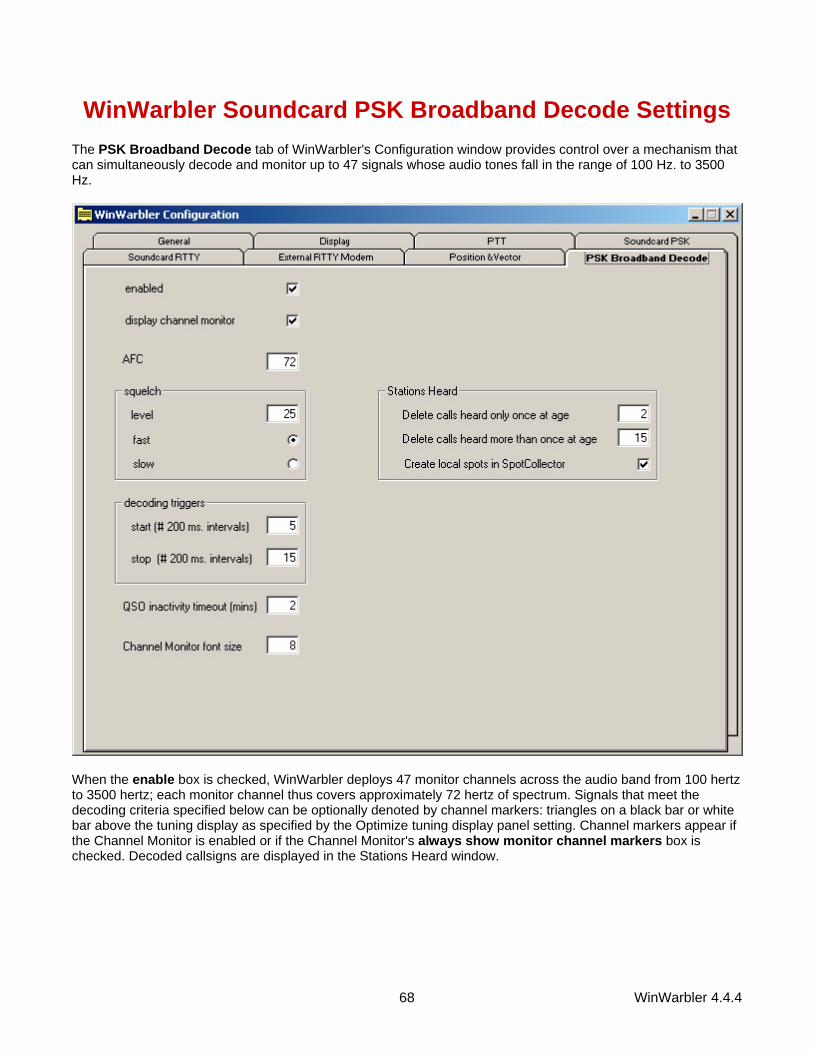
WinWarbler 4.4.4 68
WinWarbler Soundcard PSK Broadband Decode Settings The PSK Broadband Decode tab of WinWarbler's Configuration window provides control over a mechanism that can simultaneously decode and monitor up to 47 signals whose audio tones fall in the range of 100 Hz. to 3500 Hz.
When the enable box is checked, WinWarbler deploys 47 monitor channels across the audio band from 100 hertz to 3500 hertz; each monitor channel thus covers approximately 72 hertz of spectrum. Signals that meet the decoding criteria specified below can be optionally denoted by channel markers: triangles on a black bar or white bar above the tuning display as specified by the Optimize tuning display panel setting. Channel markers appear if the Channel Monitor is enabled or if the Channel Monitor's always show monitor channel markers box is checked. Decoded callsigns are displayed in the Stations Heard window.

WinWarbler 4.4.4 69
When the Channel Monitor panel's enable box is checked, WinWarbler displays a Channel Monitor window that displays the following information for each monitor channel:
• frequency • signal quality • signal strength • receiving_callsign • transmitting_callsign • decoded text (this text either scrolls left to right or is painted right to left as specified by the decoded text
panel setting) The AFC control specifies the maximum track-able excursion from a PSK signal's center frequency in hertz for each monitor channel. 0 disables AFC; the maximum value is 1000 hertz. Half the monitor channel range -- 36 hertz -- is a good starting value for this setting. The Squelch panel provides controls that set the squelch level and speed for all monitor channels. If an incoming signal's quality is below that of the specified squelch level, characters are not decoded. The minimum value 0 disables all squelch action, whereas the maximum value of 99 disables all decoding. A squelch level of 25 with fast action is a reasonable initial setting. The Decoding Triggers panel provides settings that determine whether a monitored channel is considered to be tracking a viable PSK signal. WinWarbler checks each monitor channel's signal quality every 200 ms and assigns it a state. Initially, each monitor channel's state is unlocked. If a monitor channel's signal quality exceeds the squelch level, a counter is incremented, and that monitor channel is considered to be locking; if the signal quality falls below the squelch level, the counter is zeroed, and the monitor channel is considered to be unlocked. If the counter reaches the value specified in the Start setting, the monitor channel is considered locked, which enables the subsequent extraction of callsign information from the decoded text. WinWarbler continues to sample a locked monitor channel's signal quality every 200 ms. If the signal quality falls below the squelch level, a counter is incremented and the monitor channels is considered to be unlocking. If the signal quality subsequently exceeds the squelch level, the counter is zeroed and the channel is again considered locked. If the counter reaches the value specified in the Stop setting, the monitor channel is considered unlocked, and callsign extraction is discontinued. Each monitor channel is managed individually through the four states: unlocked, locking, locked, and unlocking. The state of each monitor channel is indicated by the color of the font used to render its channel number in the Channel Monitor window:
State Channel # Font Color Unlocked black Locking magenta Locked red Unlocking blue
The QSO Inactivity Timeout determines how long a monitor channel can remain unlocked before its captured callsign information is discarded. Since WinWarbler may only be monitoring one side of a QSO, 2 minutes is a reasonable value for this setting.

WinWarbler 4.4.4 70
The Stations Heard panel provides setting that govern the list of transmitting stations displayed in the Stations Heard window:
Setting Effect
delete calls heard only once at age
If a Station Heard list entry's transmitting callsign has been decoded only once, delete the entry after the specified number of minutes elapse without decoding the callsign again (default is 2 minutes)
delete calls heard more than once at age
If a Station Heard list entry's transmitting callsign has been decoded more than once, delete the entry after the specified number of minutes elapse without decoding the callsign again (default is 15 minutes)
font size specified the font size used to display entries in the Stations Heard list
display quality and strength when checked, each entry in the Station Heard list includes the signal quality and signal strength
display decoded text
when checked, each entry in the Station Heard list includes decoded text; this text either scrolls left to right or is painted right to left as specified by the decoded text panel setting
create local spots in SpotCollector If checked, transmitting callsigns will be locally spotted in SpotCollector each time they are decoded after the first time they are decoded
The decoded text panel determines whether decoded displayed in Channel Monitor entries and Stations Heard entries scrolls continuously from left to right, or is painted right to left.
WinWarbler 4.4.4 71
RTTY with WinWarbler Using your soundcard's analog-to-digital and digital-to-analog conversion capabilities, WinWarbler allows you to conduct RTTY QSOs. To begin RTTY operation, click the RTTY button in the Mode panel located in the lower right corner of WinWarbler's main window. You can specify a set of commands to be executed whenever WinWarbler switches to RTTY mode by setting up a RTTY startup macro WinWarbler provides two independent means of sending and receiving RTTY signals:
• using your soundcard's analog-to-digital and digital-to-analog conversion capabilities • using an external modem, such as a Kantronics KAM or Timewave PK232
When first installed, soundcard RTTY is enabled and RTTY via external modem is disabled. When you click the RTTY button (in the main window's Mode panel), you'll see a single receive pane and a single transmit pane; the channel label to the left of the receive pane is S (for Soundcard RTTY). WinWarbler uses JE3HHT's MMTTY engine; an icon representing this application will appear in your Windows task bar while soundcard RTTY is in progress; note that the MMTTY engine can take much longer to start and stop if a virus scanner is running on your PC. Once MMTTY is running, WinWarbler graphically presents a 4 kHz waterfall display, allowing you to specify your mark frequency by simply pointing and clicking with your PC's mouse. While WinWarbler supports soundcard RTTY operation immediately after installation, additional controls are provided -- including access to MMTTY's demodulation parameters.
• Annotated main window capture • Reception via soundcard
o Tuning o Viewing o Transceiver Control o Optimizing the Audio Frequency Offset
• Transmission via soundcard • Logging • Macros
If you have an external modem connected to your PC via a serial port, you can enable a second receive pane -- its channel label is X (for eXternal modem). With both soundcard and external modem receive panes active, you can decode the same signal simultaneously (diversity decoding), or simultaneously monitor nearby signals -- such as a DX station and her pileup. Clicking a receive pane selects it, meaning that subsequent transmission will use that pane's associated mechanism (soundcard or external modem); the currently selected pane is distinguished by a red channel label on its left-hand border. If Commander is running, selecting a pane will place your transceiver in the appropriate mode, as specified by soundcard and external modem configuration settings.
• Annotated main window capture • Reception via soundcard • Transmission via soundcard • Logging • Macros
External modem commands are specified in files located in WinWarbler's Modems subfolder. WinWarbler includes files for the KAM and PK232. You can modify these files, or create files for other modem models using a simple command syntax.

WinWarbler 4.4.4 72

WinWarbler 4.4.4 73
WinWarbler Soundcard RTTY Reception Tuning A RTTY signal involves two frequencies, referred to as mark and space; the sequence of 1s and 0s representing a character are conveyed by appropriately switching an RF carrier between these two frequencies. The switching occurs rapidly enough that, when seen on a PC-generated audio spectrum display, a RTTY signal appears as two peaks and on a waterfall display as two lines. By definition, mark is the lower of these two frequencies, and space is the higher of the two; most amateur RTTY uses a shift - the frequency difference between the mark and space frequencies -- of 170 Hz. By convention, most amateur RTTY is transmitted on lower sideband (LSB). Thus when viewing a RTTY signal on a spectrum or waterfall display whose frequency increases from right to left, the left-most peak or line represents the signal's space frequency, and the right-most frequency or line represents its mark frequency. To avoid confusion, RTTY operators refer to a station's mark frequency when making schedules or reporting QSOs. So when P51DX is spotted on 14,085.52, it means that his mark frequency is 14,085.52 kHz and his space frequency is 14085.35 ( assuming a standard 170 Hz shift):
The tuning display at the bottom of WinWarbler's main window provides a visual indication of RTTY activity across a 2.9 kHz frequency range; the top of this range is set by the contents of the xcvr freq selector (in kHz), located in the QSO information panel. Note that your transceiver's bandwidth and filter settings may attenuate signals in parts of this range. You can select a waterfall or spectrum display, using settings in the Tuning Display sub-panel. A waterfall display can be presented in monochrome, or synthetic color using a color lookup table devised by AE4JY; a gain setting allows you to further control this form of tuning display. The spectrum display's trace color is set by the trace color setting; its background color is fixed at black. If sub-band highlighting is enabled, the frequency scale above the tuning display is rendered in green for frequencies within RTTY sub-bands, and in red for frequencies outside of RTTY sub-bands; you can customize the definition of these sub-bands. The tuning display shows the mark and space frequencies as yellow traces. You can change the colors of these traces via WinWarbler's display settings. You can control the width of these traces via the frequency trace width setting. If the transmit panel's net control is not checked, WinWarbler's transmit mark and space frequencies will appear in the tuning display as a red traces. Decoding and transmission are only possible if the mark and space tones are greater than 100 Hz, and less than 3000 Hz; if you select mark and space frequencies outside this range, the traces will be shown as dotted rather than solid lines. To change soundcard RTTY frequency, click in the tuning display to choose a new mark frequency; the frequency you select will appear in the receive panel. If there's a nearby signal and the Automatic Frequency Control box (AFC) is checked, WinWarbler will adjust its frequency to track that signal. If you are simultaneously receiving RTTY via both soundcard and external modem, you must first select the soundcard RTTY receive pane before clicking on a new mark frequency. Do so by clicking the mouse anywhere within the soundcard RTTY receive pane -- its channel label will turn red to indicate this selection.

WinWarbler 4.4.4 74
Clicking the Default button in the Main window's RTTY Receive panel sets the mark and space frequencies to default values determined by the AFSK Optimal Offset or FSK Optimal Offset and the Shift settings:
Modulation Mark Frequency Space Frequency AFSK carrier + AFSK Optimal Offset + ( Shift/2) carrier + AFSK Optimal Offset - ( Shift/2) FSK carrier + FSK Optimal Offset + ( Shift/2) carrier + FSK Optimal Offset - ( Shift/2)
The signal quality indicator in the Receive panel displays the quality of the signal being received by the selected channel. You can adjust the squelch threshold setting by clicking within the signal quality indicator. The receive panel's XY display plots the mark and space frequencies as ovals; when these two ovals are at right angles, the signal is properly tuned. if you find the waterfall or spectrum scope sufficient for tuning, you can disable the XY display and reduce the load on your PC. To optimize reception, you can enable MMTTY's bandpass filter by checking the BPF check box. The shape of this filter can be controlled via the MMTTY Setup dialog. If the station you're monitoring is transmitting reversed tones, check the Receive panel's reverse box; to transmit reversed tones. Modifying this checkbox automatically updates the receive setting in the Reverse panel on the Config window's RTTY tab. Decoding Using the MMTTY Setup dialog, you can configure the MMTTY engine to use one of three discriminators: an Infinite Impulse Response (IIR) resonator, a Finite Impulse Response (FIR) filter, or a Phase-locked Loop (PLL). You can can adjust the IIR resonator's bandwidth, or specify the number of taps in the FIR filter. Besides discriminator settings, you can also configure the limiter and the low-pass filter. Providing all of these settings makes MMTTY exceptionally flexible; however, tweaking this many settings while trying to work BQ9P through the auroral flutter is clearly impractical. To address this problem, MMTTY provides profiles. A profile is a named array of values for each of MMTTY's decoding settings. When you select a profile, all of MMTTY's decoding settings are simultaneously established. MMTTY lets you define up to 8 profiles; profile definitions are stored in a file named USERPARA.INI that resides in your WinWarbler folder. The USERPARA.INI provided in WinWarbler's Profiles folder contains 5 predefined profiles:
• standard RTTY • fluttered signals • fluttered signals (FIR) • multi-path • 23hz RTTY
To gain access to the above profiles, copy USERPARA.INI from the WinWarbler/Profile sub-folder to the WinWarbler folder before starting WinWarbler. WinWarbler lets you choose from among the profiles in your USERPARA.INI file via the Profile Selector in the Main window's RTTY Receive panel. Selecting a profile can change MMTTY's Unshift On Space, Reverse, and Keyboard Mode settings; you may need to modify these settings if they don't match your setup and/or preferences. You can use MMTTY to customize the above profiles, or create new ones that you can access via WinWarbler. If you've developed your own profiles using MMTTY, copy the USERPARA.INI file from your MMTTY folder to your WinWarbler folder. You can also directly edit your USERPARA.INI file with a text editor like Notepad, but the codes found in this file are terse and undocumented. Viewing Information decoded from the receive frequency is sequentially appended to the soundcard RTTY display pane. The display pane has a vertical scrollbar along its right side, allowing you to view information which has scrolled off the pane. The only limit to each display pane's information retention is the amount of free space on the disk drive hosting WinWarbler. You can change the font name, style, size, and color used to display this information via WinWarbler's display settings.

WinWarbler 4.4.4 75
If you are simultaneously receiving RTTY via both soundcard and external modem, their receive panes are separated by a "splitter" bar; by dragging this bar with the left mouse button, you can reallocate available screen space between the two panes. Clicking the right mouse button over a receive pane produces a pop-up menu that includes an Equalize all receive panes entry; selecting this entry equally divides the available space between the soundcard RTTY receive pane and the external modem receive pane. Because RTTY uses the LTRS character to switch from sending characters in the figures set to characters in the letters set, and the FIGS character to switch from sending characters in the letters set to characters in the figures set, a garbled LTRS or FIGS character can result in the misinterpretation of the subsequent word. To compensate for this, clicking on a received word while depressing the Ctrl key will replace the each character in that word with its analog in the opposite set, and toggle the character's underlining in the Receive Pane. If you receive a garbled word, try Ctrl-clicking it; if that doesn't make it intelligible, Ctrl-click it again to return it to its original state.
• The figures character Bel (the analog of S in the letters set) is rendered as ~. • For this purpose, a word is considered to be a sequence of characters delimited by a space or newline
character; each Receive pane acts as if it begins and ends with a newline character. To freely scroll a receive pane, you must first suspend the pane's display of incoming information; do so by clicking on the color-coded panel to the left of the pane you wish to scroll. A pane's channel label blinks while it is suspended. To resume the display of incoming information -- including that which arrived while the display was suspended, click on the color-coded panel to the left of the pane. You can suspend a pane for up to an hour without loss of incoming information. To copy text from a receive pane to the Windows clipboard, use the standard Windows left-click and drag gesture. This gesture automatically suspends the pane. Click on the color-coded panel to the left of the pane to resume the pane's display of incoming information. To facilitate logging, double-clicking on a word in a receive pane copies that word to the appropriate QSO Info panel item. The contents of the QSO Info panel items are maintained separately for each receive channel; whenever you switch channels, these items are updated to reflect whatever information you have captured from that channel. This makes it easy to incrementally capture information as you monitor several QSOs. Clicking the right mouse button over a receive pane produces a pop-up menu with four commands:
• Save receive pane to file copies the contents of that pane to a file you select via a standard Windows file selector
• View pane archive displays the contents of the pane's archive file, if it exists • Equalize all receive panes divides the available space equally between the soundcard RTTY receive
pane and the external modem RTTY receive pane if both soundcard RTTY and external modem RTTY are enabled
• Clear receive pane deletes the contents of that pane. Transceiver Control WinWarbler automatically interoperates with Commander, an transceiver control program for Icom, TenTec, Kenwood, and Yaesu radios. If WinWarbler and Commander are running simultaneously, WinWarbler's xcvr freq selector will automatically track your transceiver's frequency as you QSY; it does not matter in what order the two programs are started. If you modify the contents of the xcvr freq selector and then strike the Enter key, or if you select a new frequency, WinWarbler will direct Commander to QSY your transceiver to the specified frequency

WinWarbler 4.4.4 76
Optimizing the Audio Offset Frequency The frequency shown in the Receive panel is the sum of two components: your transceiver frequency, and an audio offset frequency in the range of 0 to 4000 Hz. Your transceiver's filters may make it difficult to receive and/or transmit signals that fall near the lower or upper ends of its audio passband. Furthermore, transmitting with a low audio offset -- say 1 kHz -- can generate harmonics that fall within your transmitter's passband and therefore produce QRM up the band. If Commander is running, clicking the Opt button directs it to change your transceiver's frequency so that the center audio offset (the midpoint between the Mark and Space audio offsets) is a value you specify for AFSK operation or a value you specify for FSK operation. Since the transceiver frequency and audio offset frequency are simultaneously adjusted, you can use this function during reception and lose no more than a character or two. You can also activate this function by right-clicking in the waterfall or spectrum display while depressing the CTRL key; if the waterfall right-click box is checked, you can activate this function by right-clicking in the waterfall or spectrum display without depressing the CTRL key. The opt button is disabled if Commander is not running; it is also disabled during transmission.

WinWarbler 4.4.4 77
WinWarbler Soundcard RTTY Transmission If the waterfall right-click box is unchecked, right-clicking in the tuning display unchecks the net setting and sets the transmission frequency; if the waterfall right-click box is checked, you must depress the CTRL key while right-clicking in the tuning display to set the transmission frequency. Checking the net box causes transmission frequency to automatically follow the selected receive channel's frequency; the net box will automatically be unchecked and disabled if operating in FSK. The transmission frequency is continuously displayed in the transmit panel. Information to be transmitted is entered into the transmit pane by direct keystroke; to clear information entered into the transmit pane, click the X button on the transmit pane's right margin. To increase the number of text lines visible in the transmit pane, click the resize button on the transmit pane's right margin. Sixteen macro buttons provide an alternative means of supplying information to be transmitted; macros can automatically transmit your callsign, the callsign, name, and QTH of the station with whom you are in QSO, incoming and outgoing signal reports, the current UTC time or date, and the contents of files. To initiate transmission, click the Start button in the transmit panel, or strike the F2 key, or strike the Insert key; the Start button is immediately disabled, and remains so until transmission terminates. Initiating transmission enables the transmit panel's Stop, and Abort buttons. As information is transmitted, its displayed in the currently selected receive pane using a white font to differentiate it from received information. If you are simultaneously receiving RTTY via both soundcard and external modem and wish to transmit via the soundcard, you must select the soundcard RTTY receive pane before initiating transmission; do so by clicking the mouse anywhere within the soundcard RTTY receive pane -- its channel label will turn red to indicate this selection. To terminate transmission when all information to be transmitted has been sent, click the Stop button in the transmit panel, or strike the F4 key, or strike the Enter key while depressing the CTRL key. To immediately terminate transmission, click the Abort button in the transmit panel, or strike the Esc key. Any un-transmitted information is discarded. Clicking the right mouse button on the transmit display pane produces a pop-up menu with two commands:
• Paste (transmit from clipboard) starts transmission, and then transmits the contents of the Windows clipboard; click the Abort button to terminate this operation before it is complete.
• Transmit file presents a Windows file selector with which to choose a file to be transmitted, starts transmission, and then transmits the contents of the selected file click the Abort button to terminate this operation before it is complete.
Entering CTRL-V into the transmit display pane also initiates the Paste (transmit from clipboard) operation. If you are using AFSK, you can transmit reversed tones by checking the Transmit panel's reverse box. Modifying this checkbox automatically updates the transmit setting in the Reverse panel on the Config window's RTTY tab.

WinWarbler 4.4.4 78
WinWarbler RTTY Reception Via External Modem Tuning Soundcard RTTY makes an excellent tuning indicator for your external modem; simply enable it, and refer to the soundcard RTTY tuning section. Viewing Information decoded by your external modem is sequentially appended to the soundcard RTTY receive pane. The receive pane has a vertical scrollbar along its right side, allowing you to view information which has scrolled off the pane. The only limit to each receive pane's information retention is the amount of free space on the disk drive hosting WinWarbler. You can change the font name, style, size, and color used to display this information via WinWarbler's display settings. If you are simultaneously receiving RTTY via both soundcard and external modem, their receive panes are separated by a "splitter" bar. You can move this splitter bar by placing the mouse cursor overtop it; when the mouse cursor changes to a double-headed arrow, use the left mouse button to drag the splitter to its desired location, reallocating available screen space between the adjacent receive panes. Clicking the right mouse button over a receive pane produces a pop-up menu that includes an Equalize all receive panes entry; selecting this entry equally divides the available space between the soundcard RTTY receive pane and the external modem receive pane. Because RTTY uses the LTRS character to switch from sending characters in the figures set to characters in the letters set, and the FIGS character to switch from sending characters in the letters set to characters in the figures set, a garbled LTRS or FIGS character can result in the misinterpretation of the subsequent word. To compensate for this, clicking on a received word while depressing the Ctrl key will replace the each character in that word with its analog in the opposite set, and toggle the character's underlining in the Receive Pane. If you receive a garbled word, try Ctrl-clicking it; if that doesn't make it intelligible, Ctrl-click it again to return it to its original state.
• The figures character Bel (the analog of S in the letters set) is rendered as ~. • For this purpose, a word is considered to be a sequence of characters delimited by a space or newline
character; each Receive pane acts as if it begins and ends with a newline character. If the station you're monitoring is transmitting reversed tones, check the Receive panel's reverse box; this automatically updates the receive setting in the Reverse sub-panel on the Config window's RTTY tab. To freely scroll a receive pane, you must first suspend the pane's display of incoming information; do so by clicking on the color-coded panel to the left of the pane you wish to scroll. A pane's channel label blinks while it is suspended. To resume the display of incoming information -- including that which arrived while the display was suspended, click on the color-coded panel to the left of the pane. You can suspend a pane for up to an hour without loss of incoming information. To copy text from a receive display pane to the Windows clipboard, use the standard Windows left-click and drag gesture. This gesture automatically suspends the pane. Click on the color-coded panel to the left of the pane to resume the pane's display of incoming information. To facilitate logging, double-clicking on a word in a receive pane copies that word to the appropriate QSO Info panel item. The contents of the QSO Info panel items are maintained separately for each receive channel; whenever you switch channels, these items are updated to reflect whatever information you have captured from that channel. This makes it easy to incrementally capture information as you monitor several QSOs.

WinWarbler 4.4.4 79
Clicking the right mouse button over a receive pane produces a pop-up menu with four commands: • Save receive pane to file copies the contents of that pane to a file you select via a standard Windows
file selector • View pane archive displays the contents of the pane's archive file, if it exists • Equalize all receive panes divides the available space equally between the soundcard RTTY receive
pane and the external modem RTTY receive pane if both soundcard RTTY and external modem RTTY are enabled
• Clear receive pane deletes the contents of that pane. Transceiver Control WinWarbler automatically interoperates with Commander, an transceiver control program for Icom, TenTec, Kenwood, and Yaesu radios. If WinWarbler and Commander are running simultaneously, WinWarbler's xcvr freq selector will automatically track your transceiver's frequency as you QSY; it does not matter in what order the two programs are started. If you modify the contents of the xcvr freq selector and then strike the Enter key, or if you select a new frequency, WinWarbler will direct Commander to QSY your transceiver to the specified frequency

WinWarbler 4.4.4 80
WinWarbler RTTY Transmission Via External Modem Information to be transmitted is entered into the Transmit Pane by direct keystroke; to clear information entered into the transmit pane, click the X button on the transmit pane's right margin. To increase the number of text lines visible in the transmit pane, click the resize button on the transmit pane's right margin. Sixteen macro buttons provide an alternative means of supplying information to be transmitted; macros can automatically transmit your callsign, the callsign, name, and QTH of the station with whom you are in QSO, incoming and outgoing signal reports, the current UTC time or date, and the contents of files. To initiate transmission, click the Start button in the transmit panel, or strike the F2 key, or strike the Insert key; the Start button is immediately disabled, and remains so until transmission terminates. Initiating transmission enables the transmit panel's CW ID , Stop, and Abort buttons. As information is transmitted, its displayed in the currently selected receive pane using a white font to differentiate it from received information. If you are simultaneously receiving RTTY via both soundcard and external modem and wish to transmit via the external modem, you must select the external modem receive pane before initiating transmission; do so by clicking the mouse anywhere within the soundcard RTTY receive pane -- its channel label will turn red to indicate this selection. To force CW identification to be sent when transmission is terminated, click the CW ID button in the transmit panel, or strike the F3 key; the CW ID button is immediately disabled, and remains so until transmission terminates. To terminate transmission when all information to be transmitted has been sent, click the Stop button in the transmit panel, or strike the F4 key, or strike the Enter key while depressing the Ctrl key. To immediately terminate transmission, click the Abort button in the transmit panel, or strike the Esc key. Any un-transmitted information is discarded. Clicking the right mouse button on the transmit display pane produces a pop-up menu with two commands:
• Paste (transmit from clipboard) starts transmission, and then transmits the contents of the Windows clipboard; click the Abort button to terminate this operation before it is complete.
• Transmit file presents a Windows file selector with which to choose a file to be transmitted, starts transmission, and then transmits the contents of the selected file click the Abort button to terminate this operation before it is complete.
Entering CTRL-V into the transmit display pane also initiates the Paste (transmit from clipboard) operation. To transmit reversed tones, check the Transmit panel's reverse box; this automatically updates the transmit setting in the Reverse sub-panel on the Config window's RTTY tab.