ansul design r-102 restaurant …r-102 restaurant fire suppression system design, installation,...
TRANSCRIPT

DESIGN R-102 RESTAURANTINSTALLATION FIRE SUPPRESSIONRECHARGE AND SYSTEMMAINTENANCE (Standard UL 300 Listed)MANUAL
ANSUL


Bulletin
S-2010156-02 Copyright © 2013 Tyco Fire Products LP. l All rights reserved.
www.ansul.com
Bulletin No. 5958DATE: October 4, 2013
TO: Authorized ANSUL® Restaurant System Distributors and OEMs
FROM: Product Management, Restaurant Systems
SUBJECT: AUTOMAN Mechanical Release Re-design
We are pleased to introduce several enhancements to all AUTOMAN Release Mechanism Assemblies for ANSUL R-102 and PIRANHA Restaurant Systems. The new features simplify installation procedures and service requirements while offering added reliability.
The following identifies the changes within the AUTOMAN Release Assemblies along with the benefits they bring you and your customers:
• Re-designed Release Mechanism: The release mechanism has been re-designed to reduce assembly time, and to increase reliability and serviceability.
Note: The high pressure port side of the cartridge receiver has been increased from 1/8 in. (3 mm) to 1/4 in. (6 mm).
• Cartridge Monitoring: The re-designed release mechanism housing allows optional cartridge monitoring using a snap-action switch, which may be wired directly to a remote notification device or into a monitoring control panel. This assures both the servicing technician and the customer that the cartridge is properly installed.
• Lock-out Mechanism: A new locking pin (versus the current locking bar) is now available, increasing the ease of locking out the release mechanism during installation and maintenance.
Action Required: You will need to purchase the Locking Pin (Part No. 438031) to install and service the new release mechanism.
• New and Improved Snap-Action Switch Installation Procedure: The re-designed release mechanism will accommodate up to four existing snap-action and/or alarm initiating switches encased in two composite enclosures:
– Having two separate switch housings allows switches to be more accurately positioned, increasing reliability and ease of installation.
– The switch housing separates the two switches. This meets UL 864 which requires a minimum of 1/4 in. (7 mm) of separation between power limited and no-power limited connections (e.g. snap-action switches connected to 120 VAC versus the alarm initiating switch connected to a low current circuit in a fire alarm panel).
– The new procedure improves protection from switch contacts when re-setting or servicing the fire suppression system.
– Larger diameter holes in the new switch mounting bracket have been designed to accommodate the screws without the need to thread them first with a thread cutting screw.

Bulletin No. 5958October 4, 2013Page 2
Bulletin
S-2012088 Copyright © 2013 Tyco Fire Products LP. l All rights reserved.
www.ansul.com
– An optional retrofit kit for current switch installations is also available. The Retrofit Switch Mounting Kit includes the following items:
2 – NEW Switch Holders (Part No. 439065)1 – NEW Switch Mounting Bracket (Part No. 439063)1 – NEW Trip Lever Pin (Part No. 438866)4 – #4-40 x 1.5 in. Machine Screws with Nuts (Part No. 415869)1 – Lock Nut (Part No. 21918)1 – Snap-Action Switch Wiring Diagram Label (Part No. 438664)1 – Retrofit Kit Installation Instructions (Part No. 438867)
Old Release Mechanism New Release Mechanism
Cartridge Monitoring Switch Placement

Bulletin No. 5958October 4, 2013Page 3
Bulletin
S-2012088 Copyright © 2013 Tyco Fire Products LP. l All rights reserved.
www.ansul.com
Snap-Action Switch Wiring Diagram(Included with each release assembly)
For detailed information on the new snap-action switch configuration using the new switch holders, refer to the Snap-Action Switch Installation Instructions (Form No. F-2013201) located on the ANSUL Distributor Portal.
The following components are available for immediate shipment and may be ordered using the information below: SuggestedPart No. Description List Price (USD)438031 Locking Pin $ 8.00438940 Switch Mounting Retrofit Kit $ 14.00
*Note: Prices are subject to change without notice. Always refer to the latest price files on the ANSUL Distributor Portal prior to ordering.
The current offerings of Snap-Action and Alarm Initiating Switch Kit assembly part numbers and prices have not changed. However, they will now include the new switch holder(s), appropriate screws, and the new trip lever pin.
The information in this bulletin will be added to the ANSUL R-102 Restaurant System Design, Installation, Recharge and Maintenance Manual (Part No. 418087-11) dated July 1, 2009, and to the PIRANHA Restaurant System Design, Installation, Recharge and Maintenance Manual (Part No. 423385-06) dated April 2, 2013 at the next manual reprint.
Should you have questions pertaining to this bulletin, please contact Technical Services as noted below.
Note: Wiring of the top switches will be opposite of the bottom switches as indicated on the wiring diagram.


Bulletin
UL EX 3470
S-2010156-02 Copyright © 2013 Tyco Fire Products LP. l All rights reserved.
www.ansul.com
Bulletin No. 5887DATE: December 17, 2012
TO: Authorized ANSUL® R-102 Restaurant System Distributors and OEMs
FROM: Product Management, Restaurant Systems
SUBJECT: UL Listing for Pitco SPINFRESH Fryers
We are pleased to announce an appliance-specific UL Listing for the ANSUL R-102 Restaurant Fire Suppression System when protecting the following Pitco SPINFRESH Deep Fat Fryer models:SSH55 SG14S SGH50SSH55R SG14RS SGH5017MEII SE14 SEH50MGII SE14R SEH5017 SE14X
Bulletin No. 5887December 17, 2012Page 2
UL EX 3470
Bulletin
S-2012089Copyright © 2013 Tyco Fire Products LP. l All rights reserved.
www.ansul.com
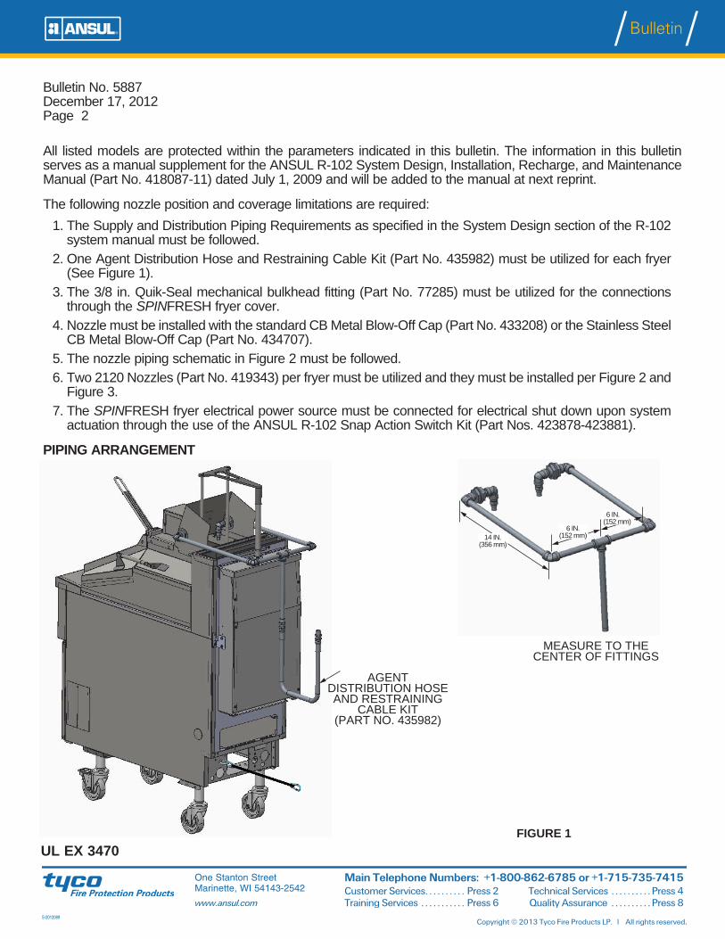
All listed models are protected within the parameters indicated in this bulletin. The information in this bulletin serves as a manual supplement for the ANSUL R-102 System Design, Installation, Recharge, and Maintenance Manual (Part No. 418087-11) dated July 1, 2009 and will be added to the manual at next reprint.
The following nozzle position and coverage limitations are required:1. The Supply and Distribution Piping Requirements as specified in the System Design section of the R-102
system manual must be followed.2. One Agent Distribution Hose and Restraining Cable Kit (Part No. 435982) must be utilized for each fryer
(See Figure 1).3. The 3/8 in. Quik-Seal mechanical bulkhead fitting (Part No. 77285) must be utilized for the connections
through the SPINFRESH fryer cover.4. Nozzle must be installed with the standard CB Metal Blow-Off Cap (Part No. 433208) or the Stainless Steel
CB Metal Blow-Off Cap (Part No. 434707).5. The nozzle piping schematic in Figure 2 must be followed.6. Two 2120 Nozzles (Part No. 419343) per fryer must be utilized and they must be installed per Figure 2 and
Figure 3.7. The SPINFRESH fryer electrical power source must be connected for electrical shut down upon system
actuation through the use of the ANSUL R-102 Snap Action Switch Kit (Part Nos. 423878-423881).
PIPING ARRANGEMENT
AGENT DISTRIBUTION HOSE AND RESTRAINING
CABLE KIT (PART NO. 435982)
FIGURE 1
14 IN. (356 mm)
6 IN. (152 mm)
6 IN. (152 mm)
MEASURE TO THE CENTER OF FITTINGS

Bulletin No. 5887December 17, 2012Page 3
UL EX 3470
Bulletin
S-2012089Copyright © 2013 Tyco Fire Products LP. l All rights reserved.
www.ansul.com
NOZZLE CROSS SECTION VIEW
FRYER FLUE
Should you have any questions regarding this bulletin, please contact Technical Services as noted below.
FIGURE 2
5.0 IN. ± 0.5 IN. (127 mm ± 13 mm)
1.375 IN. (35 mm) DIA.
2.5 IN. ± 0.5 IN. (64 mm ± 13 mm)
FIGURE 3
QUIK-SEAL ADAPTOR
CLOSE NIPPLE
ELBOW
CLOSE NIPPLE
2120 NOZZLE
6.25 IN. ± 0.125 IN. (159 mm ± 3 mm)
3.00 IN. ± 0.125 IN. (76 mm ± 3 mm) TO NOZZLE TIP

UL EX 3470
One Stanton StreetMarinette, WI 54143-2542www.ansul.com
Main Telephone Numbers: 1-800-862-6785 or 1-715-735-7415Customer Services: Press 2 • Technical Services: Press 4 • Training Services: Press 6 • Quality Assurance: Press 8
Literature Fax Orders: 1-800-543-9822 or 1-715-732-3474F-2010156
Bulletin No. 5832DATE: March 22, 2012
TO: All Authorized ANSUL Restaurant Distributors and OEMs
FROM: Product Management – Restaurant Systems
SUBJECT: Magikitch’n Gas Radiant Char-Broiler with Smoker Box – R-102 UL-Listed Protection
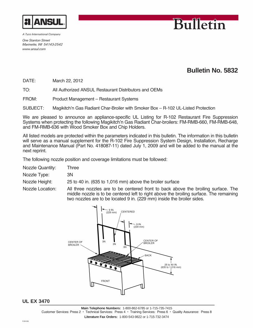
We are pleased to announce an appliance-specific UL Listing for R-102 Restaurant Fire Suppression Systems when protecting the following Magikitch’n Gas Radiant Char-broilers: FM-RMB-660, FM-RMB-648, and FM-RMB-636 with Wood Smoker Box and Chip Holders.
All listed models are protected within the parameters indicated in this bulletin. The information in this bulletin will serve as a manual supplement for the R-102 Fire Suppression System Design, Installation, Recharge and Maintenance Manual (Part No. 418087-11) dated July 1, 2009 and will be added to the manual at the next reprint.
The following nozzle position and coverage limitations must be followed:Nozzle Quantity: ThreeNozzle Type: 3NNozzle Height: 25 to 40 in. (635 to 1,016 mm) above the broiler surfaceNozzle Location: All three nozzles are to be centered front to back above the broiling surface. The
middle nozzle is to be centered left to right above the broiling surface. The remaining two nozzles are to be located 9 in. (229 mm) inside the broiler sides.
3N3N
3N
FRONT
25 to 40 IN.(635 to 1,016 mm)
BACK
CENTER OF BROILER
9 IN.(229 mm)
CENTERED9 IN.
(229 mm)
CENTER OF BROILER

Bulletin No. 5832March 22, 2012Page 2
UL EX 3470Main Telephone Numbers: 1-800-862-6785 or 1-715-735-7415
Customer Services: Press 2 • Technical Services: Press 4 • Training Services: Press 6 • Quality Assurance: Press 8Literature Fax Orders: 1-800-543-9822 or 1-715-732-3474
Smoker Box and Chip Holders cannot exceed logs 4 in. (102 mm) in diameter and a maximum allowable wood depth of 4 in. (102 mm).
Should you have questions regarding this bulletin, please contact your US Standard Product Manager or International Area Manager, or contact Technical Services as listed below.

UL EX 3470
One Stanton StreetMarinette, WI 54143-2542www.ansul.com
Main Telephone Numbers: 1-800-862-6785 or 1-715-735-7415Customer Services: Press 2 • Technical Services: Press 4 • Training Services: Press 6 • Quality Assurance: Press 8
Literature Fax Orders: 1-800-543-9822 or 1-715-732-3474F-2010156
Bulletin No. 5826DATE: February 28, 2012
TO: All Authorized ANSUL Restaurant System Distributors and OEMs
FROM: Product Management – Restaurant Systems
SUBJECT: Model 691 Dual Lift Henny Penny Pressure Fryer Protection
We are pleased to inform you that the Model 691 Dual Lift Henny Penny Pressure Fryer has been added to the UL Listed fryers that utilize the R-102 Restaurant Fire Suppression System for appliance protection.
The Henny Penny Pressure Fryer protection limitations must be followed as outlined in the ANSUL R-102 Restaurant Fire Suppression System Design, Installation, Recharge and Maintenance Manual (Part No. 418087-11). These limitations can be found in the Design section, Page 4-34.2.
The information contained in this bulletin serves as a supplement to the R-102 system manual, and the Model 691 Dual Lift Henny Penny Pressure Fryer will be added to the manual at the next issue date.
Should you have questions pertaining to this bulletin, please contact Technical Services as noted below.


UL EX-3470
One Stanton StreetMarinette, WI 54143-2542www.ansul.com
Main Telephone Numbers: 1-800-862-6785 or 1-715-735-7415Customer Services: Press 2 • Technical Services: Press 4 • Training Services: Press 6 • Quality Assurance: Press 8
Literature Fax Orders: 1-800-543-9822 or 1-715-732-3474F-2010156
Bulletin No. 5793DATE: December 22, 2011
TO: All Authorized ANSUL® R102™ System Distributors and OEM’s
FROM: Product Management – Restaurant Systems
SUBJECT: R-102 Protection Options For Nieco Jet Flow Automatic Chain Broilers
We are pleased to announce additional appliance specific R-102 fire protection options for Nieco Broiler Models: JF62, JF63, JF92, JF93 and JF143. The Nieco Broiler Models are approved with and without a catalyst.
This bulletin is a supplement to the ANSUL R-102 Design, Install, Recharge and Maintenance Manual (Part No. 418087-11) dated July 1, 2009 and is not intended to replace the requirements and limitations outlined therein. The information contained in this bulletin will be added to the manual at the next update.
The following nozzle positioning and coverage limitations must be followed:NIECO BROILER MODELS; JF62, JF63, JF92, JF93 AND JF143 - WITH OR WITHOUT A CATALYST Nozzle Type 245Nozzle Quantity OneNozzle Height 20 in. - 25 in. (508 mm - 635 mm)Nozzle Location Centered above the catalyst to 5 in. (127 mm) forward of catalyst front edgeNozzle Aim Point Center of catalyst
If you should have any questions pertaining to this bulletin, please contact your U.S. District Manager or International Area Manager; or call Technical Services at 1-800-862-6785/1-715-735-7415.
BACK FRONT
SIDE VIEW008910
TOP VIEW008911
FRONTBACK
CENTER LINE
AIM POINT
20 IN. (508 mm)
25 IN. (635 mm)
CATALYST/EXHAUST OPENING
ALLOWABLE NOZZLE LOCATION IN GRID
CENTER LINE
5 IN. (127 mm)
ALLOWABLE NOZZLE LOCATION LINE
CENTER LINE
AIM AT CENTER

R-102: UL EX. 3740PIRANHA: UL EX. 5174
One Stanton StreetMarinette, WI 54143-2542www.ansul.com
Main Telephone Numbers: 1-800-862-6785 or 1-715-735-7415Customer Services: Press 2 • Technical Services: Press 4 • Training Services: Press 6 • Quality Assurance: Press 8
Literature Fax Orders: 1-800-543-9822 or 1-715-732-3474F-2010156
Bulletin No. 5785DATE: December 5, 2011
TO: All Authorized ANSUL Restaurant System Distributors
FROM: Product Management – Restaurant Systems
SUBJECT: KRISPY KREME FRYERS – R-102 and PIRANHA Additional UL Listed Protection
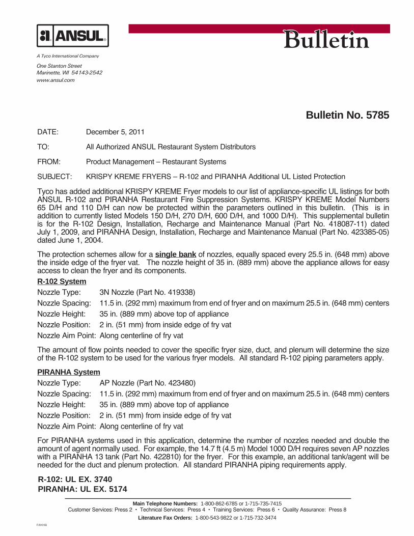
Tyco has added additional KRISPY KREME Fryer models to our list of appliance-specific UL listings for both ANSUL R-102 and PIRANHA Restaurant Fire Suppression Systems. KRISPY KREME Model Numbers 65 D/H and 110 D/H can now be protected within the parameters outlined in this bulletin. (This is in addition to currently listed Models 150 D/H, 270 D/H, 600 D/H, and 1000 D/H). This supplemental bulletin is for the R-102 Design, Installation, Recharge and Maintenance Manual (Part No. 418087-11) dated July 1, 2009, and PIRANHA Design, Installation, Recharge and Maintenance Manual (Part No. 423385-05) dated June 1, 2004.
The protection schemes allow for a single bank of nozzles, equally spaced every 25.5 in. (648 mm) above the inside edge of the fryer vat. The nozzle height of 35 in. (889 mm) above the appliance allows for easy access to clean the fryer and its components.R-102 SystemNozzle Type: 3N Nozzle (Part No. 419338)Nozzle Spacing: 11.5 in. (292 mm) maximum from end of fryer and on maximum 25.5 in. (648 mm) centersNozzle Height: 35 in. (889 mm) above top of applianceNozzle Position: 2 in. (51 mm) from inside edge of fry vatNozzle Aim Point: Along centerline of fry vat
The amount of flow points needed to cover the specific fryer size, duct, and plenum will determine the size of the R-102 system to be used for the various fryer models. All standard R-102 piping parameters apply.
PIRANHA SystemNozzle Type: AP Nozzle (Part No. 423480)Nozzle Spacing: 11.5 in. (292 mm) maximum from end of fryer and on maximum 25.5 in. (648 mm) centersNozzle Height: 35 in. (889 mm) above top of applianceNozzle Position: 2 in. (51 mm) from inside edge of fry vatNozzle Aim Point: Along centerline of fry vat
For PIRANHA systems used in this application, determine the number of nozzles needed and double the amount of agent normally used. For example, the 14.7 ft (4.5 m) Model 1000 D/H requires seven AP nozzles with a PIRANHA 13 tank (Part No. 422810) for the fryer. For this example, an additional tank/agent will be needed for the duct and plenum protection. All standard PIRANHA piping requirements apply.

Bulletin No. 5785December 5, 2011Page 2
R-102: UL EX. 3740PIRANHA: UL EX. 5174
Main Telephone Numbers: 1-800-862-6785 or 1-715-735-7415Customer Services: Press 2 • Technical Services: Press 4 • Training Services: Press 6 • Quality Assurance: Press 8
Literature Fax Orders: 1-800-543-9822 or 1-715-732-3474
Below is a reference diagram for KRISPY KREME Model 1000 D/H. The fryer vat is 14.7 ft x 38.375 in. (4.5 m x 975 mm). Smaller fryers maintain the same nozzle spacing as shown below. Nozzle spacing will determine the number of nozzles needed for each size appliance. See parameters on Page 1 for reference to nozzle spacing requirements. The diagram is applicable for both R-102 and PIRANHA Restaurant Fire Suppression Systems.
System installations and updates to KRISPY KREME fryers must have prior authorization from KRISPY KREME Corporation. This will be done via purchase order format. Local franchises cannot authorize either installations or updates. Contact information is as follows:
Jim Koch Krispy Kreme Doughnut Corporation 3190 Centre Park Boulevard Winston-Salem, NC 27107 Phone: 336-726-8908 Fax: 336-725-6301
If you have questions pertaining to this bulletin, please contact your U.S. District Manager or International Area Manager; or call Technical Services as listed below.
CL
LC
006908
CL
35"
006908a
35 IN. (889 mm)
11.5 IN. (292 mm)
25.5 IN. (648 mm)
25.5 IN. (648 mm)
25.5 IN. (648 mm)
25.5 IN. (648 mm)
25.5 IN. (648 mm)
25.5 IN. (648 mm)
11.5 IN. (292 mm)
35 IN. (889 mm)
2 IN. (51 mm)

UL EX3470
One Stanton StreetMarinette, WI 54143-2542www.ansul.com
Main Telephone Numbers: 1-800-862-6785 or 1-715-735-7415Customer Services: Press 2 • Technical Services: Press 4 • Training Services: Press 6 • Quality Assurance: Press 8
Literature Fax Orders: 1-800-543-9822 or 1-715-732-3474F-2010156
Bulletin No. 5711DATE: January 4, 2011
TO: All Authorized ANSUL R-102 System Distributors and OEM’s
FROM: Product Management, Restaurant Systems
SUBJECT: Duke Gas Chain Broiler Protection UPDATE / CORRECTION – Model FBB
We were recently informed that the current Duke Gas Chain Broiler Model FBB has an exhaust opening size of 9 in. (229 mm) wide x 26.75 in. (679 mm) long. This is a change from the originally tested chain broiler that had an opening size of 6.25 in. (159 mm) wide x 26.75 in. (679 mm) long. Therefore, additional Underwriters Laboratories testing was conducted for the ANSUL R-102 system protection of the Duke Chain Gas Broiler Model FBB with the wider exhaust opening which may incorporate a catalyst and/or riser.
As a result, new protection parameters require that the 290 Nozzle (Part No. 419342) be used for high proximity protection in place of the 2W Nozzle for Duke Gas Chain Broiler Model FBB with an exhaust opening of 9 in. (229 mm) wide x 26.75 in. (679 mm) long. To maintain the UL listed protection, this change out must be completed at your next scheduled service/maintenance appointment.
High Proximity Protection - Duke Gas Chain Broiler with exhaust opening of 9 in. (229 mm) wide x 26.75 in. (679 mm) long - with or without catalyst and/or riser.
NOTE: Nozzle placement is the same as currently listed in the R-102 System Manual (Part No. 418087-11) with the exception of the nozzle height range of 15 to 20 in. (381 to 508 mm).
• Nozzle Type: 290 Nozzle (Part No. 419342)• Nozzle Quantity: One• Nozzle Height: 15 to 20 in. (381 to 508 mm) above the top of the appliance• Nozzle Location: Centered 6.5 in. (165 mm) forward from back edge of the appliance• Nozzle Aiming Point: Center of opening
PRODUCT OUTPUT
(1) - 290 NOZZLE
6 1/2 IN. (165 mm) FROM EDGE OF
APPLIANCE THAT DEFLECTOR PLATE IS
ANGLED TOWARD
15 IN. (381 mm) TO 20 IN. (508 mm) NOZZLE HEIGHT
PRODUCT INPUT
008661 008662
BACK FRONT
6 1/2 IN. (165 mm) FROM EDGE OF
APPLIANCE THAT DEFLECTOR PLATE IS
ANGLED TOWARDS
PRODUCT OUTPUT
EXHAUST OPENING 9 IN. (229 mm) x 26.75 IN.
(679 mm)
PERFORATED GRILL
CENTER DUCT
PRODUCT INPUT
SIDE VIEW TOP VIEW
Bulletin No. 5711January 4, 2011Page 2
UL EX3470Main Telephone Numbers: 1-800-862-6785 or 1-715-735-7415
Customer Services: Press 2 • Technical Services: Press 4 • Training Services: Press 6 • Quality Assurance: Press 8
Literature Fax Orders: 1-800-543-9822 or 1-715-732-3474
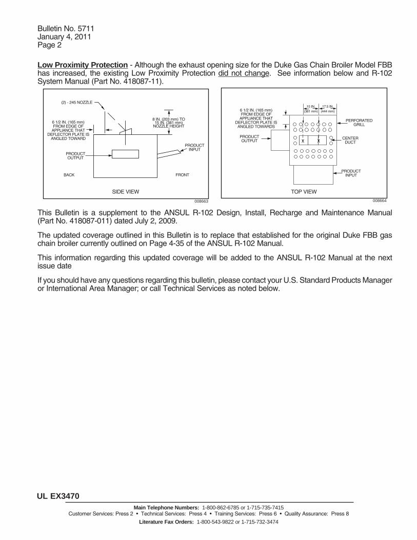
Low Proximity Protection - Although the exhaust opening size for the Duke Gas Chain Broiler Model FBB has increased, the existing Low Proximity Protection did not change. See information below and R-102 System Manual (Part No. 418087-11).
This Bulletin is a supplement to the ANSUL R-102 Design, Install, Recharge and Maintenance Manual (Part No. 418087-011) dated July 2, 2009.
The updated coverage outlined in this Bulletin is to replace that established for the original Duke FBB gas chain broiler currently outlined on Page 4-35 of the ANSUL R-102 Manual.
This information regarding this updated coverage will be added to the ANSUL R-102 Manual at the next issue date
If you should have any questions regarding this bulletin, please contact your U.S. Standard Products Manager or International Area Manager; or call Technical Services as noted below.
X X
PRODUCT OUTPUT
(2) - 245 NOZZLE
6 1/2 IN. (165 mm) FROM EDGE OF
APPLIANCE THAT DEFLECTOR PLATE IS
ANGLED TOWARD
8 IN. (203 mm) TO 15 IN. (381 mm)
NOZZLE HEIGHT
PRODUCT INPUT
008663 008664
BACK FRONT
6 1/2 IN. (165 mm) FROM EDGE OF
APPLIANCE THAT DEFLECTOR PLATE IS
ANGLED TOWARDS
PRODUCT OUTPUT
15 IN. (381 mm)
PERFORATED GRILL
CENTER DUCT
PRODUCT INPUT
SIDE VIEW TOP VIEW
17.5 IN. (444 mm)

UL/ULC EX3470
One Stanton StreetMarinette, WI 54143-2542www.ansul.com
Main Telephone Numbers: 1-800-862-6785 or 1-715-735-7415Customer Services: Press 2 • Technical Services: Press 4 • Training Services: Press 6 • Quality Assurance: Press 8
Literature Fax Orders: 1-800-543-9822 or 1-715-732-3474
Bulletin No. 5674DATE: August 20, 2010
TO: All Authorized ANSUL Restaurant System Distributors and OEM’s
FROM: Product Management, Restaurant Systems
SUBJECT: FryMaster Energy Efficient RE 14 Fryer Model
Tyco Fire Suppression and Building Products is pleased to announce an appliance-specific UL Listing for the ANSUL R-102 Fire Suppression System when protecting the FryMaster Energy-Efficient RE 14 Fryer Model. The information within this bulletin is a supplement to the ANSUL R-102 Fire Suppression System Manual (Part No. 418087-11) and will be included at the next manual update.
The electric fryer can be protected with either a single 230 Nozzle located 27 to 47 in. (69 to 120 cm) above the top surface of the fryer or with a single 245 Nozzle located 20 to 27 in. (51 to 69 cm) above the top surface of the fryer.
Either nozzle must be located anywhere along or within the perimeter of the cooking surface and aimed at the midpoint. See illustration below.
The maximum size of the fry pot (without drip board) is 14 x 15 1/2 in. (35.5 x 39.4 cm) and the maximum size of the cooking surface (with drip board) is 14 x 20 7/8 in. (35.5 cm x 53 cm). The vat may be divided in half to make two split vats.
If you should have any questions regarding this bulletin, please contact your U.S. Standard Products Manager or International Area Manager or call Technical Services as noted below.
F-2010156
230 NOZZLE TIP OR 245 NOZZLE TIP ANYWHERE ALONG OR WITHIN THE PERIMETER OF THE COOKING SURFACE AND AIMED AT THE MIDPOINT.
20 7/8 IN.(53 cm)MAXIMUM
14 IN.(35.3 cm)MAXIMUM
230 NOZZLE
230 NOZZLE27 IN. – 47 IN.(69 cm – 120 cm) ABOvE TOPSURFACEOF FRYER
245 NOZZLE20 IN. – 27 IN.(51 cm – 69 cm)ABOvE TOPSURFACE OF FRYER
15 1/2 IN. (39.4 cm)MAXIMUM
245 NOZZLE


One Stanton StreetMarinette, WI 54143-2542www.ansul.com
UL EX3470Main Telephone Numbers: 1-800-862-6785 or 1-715-735-7415
Customer Services: Press 2 • Technical Services: Press 4 • Training Services: Press 6 • Quality Assurance: Press 8
Literature Fax Orders: 1-800-543-9822 or 1-715-732-3474
Bulletin No. 5650DATE: April 16, 2010
TO: Authorized ANSUL R-102 System Distributors and OEM’s - EMEA
FROM: Product Management – Restaurant Systems
SUBJECT: R-102 ANSUL AUTOMAN 24-VDC Electric Regulated Release Assemblies
We are pleased to announce the availability of two new UL Listed ANSUL AUTOMAN 24-VDC Electric Regulated Release Assemblies for the R-102 Restaurant Fire Suppression System. Both the standard and OEM versions of the 24-VDC Electric Regulated Release Assemblies are listed for use with the AUTOPULSE Control Panels. The new 24-VDC Electric Regulated Release Assemblies can be wired in the releasing circuits of the control panels for actuation, allowing NFPA 72 compliant electrical operation, including simultaneous operation of multiple R-102 systems as well as electric detection and electric pull stations.
The installation requirements and limitations outlined in the R-102 Restaurant Manual for Part No. 429859 ANSUL AUTOMAN 24-VDC Regulated Release should be followed for Part No. 437324 ANSUL AUTOMAN 24-VDC OEM Regulated Release as well. Cocking lever Part No. 26310 for AUTOMAN IIC must be used on the 24-VDC Regulated Release assemblies.
The new 24VDC Regulated Release Assemblies also include a major enhancement. The presence of the expellant gas cartridge can be electrically monitored using the supervision circuit of the releasing panel. When the cartridge is removed, the contacts of the supervision switch close and send an alarm to the panel. The wiring schematic on Page 2 should be followed.
The ANSUL AUTOMAN 24-VDC Electric Regulated Release Assemblies can be purchased under the following part numbers and are available for immediate shipment.
Part No. Description429859 ANSUL AUTOMAN 24-VDC Regulated Release 437324 ANSUL AUTOMAN 24-VDC OEM Regulated Release26310 Cocking Lever for 24-VDC Release
Installation of the 24-VDC Electric Regulated Release must be in accordance with the limitations outlined in the following documents.
• R-102 Restaurant Fire Suppression System Manual (Part No. 418087-11)• ANSUL AUTOMAN IIC Releasing Device Manual (Part No. 17788-09), • If used: AUTOPULSE Z-10 Agent Releasing Installation, Program and Operations Manual (Part No.
430545 – 02) • If used: AUTOPULSE 542R Agent Releasing Installation Manual (Part No. 434946-01).
If you should have any questions regarding this bulletin, please contact your U.S. Standard Products Manager or International Area Manager; or call Technical Services as noted below.

Bulletin No. 5650April 16, 2010Page 2
UL EX3470Main Telephone Numbers: 1-800-862-6785 or 1-715-735-7415
Customer Services: Press 2 • Technical Services: Press 4 • Training Services: Press 6 • Quality Assurance: Press 8
Literature Fax Orders: 1-800-543-9822 or 1-715-732-3474
CAUTIONDo not install cartriDge or remove tank assembly unless release is cockeD anD ring pin is in place!if the following occurs During maintenance or installation, the solenoiD for this releasing Device may be DamageD, renDering the system inoperable:1. if the release is el ec trically trippeD (fireD) with the ring pin inserteD such that the
release mechanism is pinneD in the cockeD position.2. the lever arm of the mounteD switch is bent such that the switch Does not operate
when the release roll pin is bottomeD out in the fireD position.3. if you try to re cock the release mechanism while power is applieD to the release
through the alarm contacts.for complete re charg ing, inspection anD maintenance in struc tions, refer to ap plicable fire sup pression system manual.
cautionelectrical shock hazarD
wiriNg NOTES:1. to be connecteD to a
nom inal 24 vDc releasing circuit.
input power: 750 ma at 24 vDc nominal (1.02a at 30vDc maX.).
2. polarization: observe po larity when con necteD to a release circuit; termi nal 4 pos itive, terminal 8 negative.
3. all interconnecting wir ing number 1418 awg.
4. s1 anD s2 contact rat ings:
20 a, 125/250 vac 2 hp, 250 vac 1 hp, 125 vac.
5. sol1 coil resistance: 28 ohms ± 10% at 77 °f (25 °c)
6. install the inline su pervisory Device sDx across terminals 4 anD 5. refer to the releasing panel installation in structions for su pervisory Device re quirements. if an inline su pervisory De vice is not requireD, install jumper j2 across terminals 4 anD 5.
7. s3 contact ratings: 24vDc, 250 ma maX.
s1 anD s2 transfer upon actuation of release
voltage transient suppressor
or
current limiting resistor
ul listeD superviseD releasing control unit
j1
tz1
*s1
s3
sDx
sol1
accessorypowersource
* auXiliary alarming Devices, see s1 ratings ** fuel shutoff valve, blower motor, Door closer, etc., see s1 ratings *** contacts shown in “cartriDge present” conDition. contacts close upon
cartriDge removal.
high
low
008468
*** cartriDge supervision switch
inline supervisory Device
nc
s2
nc
tb1
**
j2
One Stanton StreetMarinette, WI 54143-2542www.ansul.com
UL EX3470Main Telephone Numbers: 1-800-862-6785 or 1-715-735-7415
Customer Services: Press 2 • Technical Services: Press 4 • Training Services: Press 6 • Quality Assurance: Press 8
Literature Fax Orders: 1-800-543-9822 or 1-715-732-3474
Bulletin No. 5641DATE: March 19, 2010
TO: All Authorized ANSUL R-102™ Restaurant System Distributors and OEM’s
FROM: Product Management – Restaurant Systems
SUBJECT: Bakers Pride Broiler with Smoker Box – R-102 UL-Listed Protection
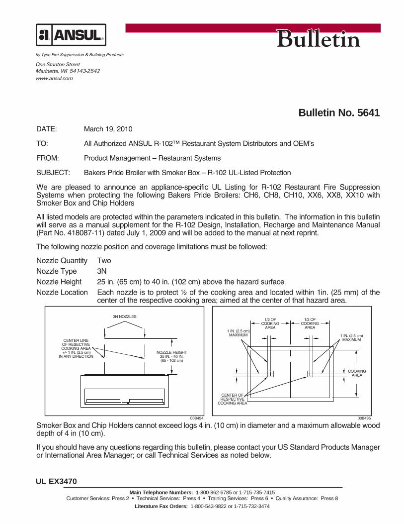
We are pleased to announce an appliance-specific UL Listing for R-102 Restaurant Fire Suppression Systems when protecting the following Bakers Pride Broilers: CH6, CH8, CH10, XX6, XX8, XX10 with Smoker Box and Chip Holders
All listed models are protected within the parameters indicated in this bulletin. The information in this bulletin will serve as a manual supplement for the R-102 Design, Installation, Recharge and Maintenance Manual (Part No. 418087-11) dated July 1, 2009 and will be added to the manual at next reprint.
The following nozzle position and coverage limitations must be followed:
Nozzle Quantity TwoNozzle Type 3NNozzle Height 25 in. (65 cm) to 40 in. (102 cm) above the hazard surfaceNozzle Location Each nozzle is to protect ½ of the cooking area and located within 1in. (25 mm) of the
center of the respective cooking area; aimed at the center of that hazard area.
Smoker Box and Chip Holders cannot exceed logs 4 in. (10 cm) in diameter and a maximum allowable wood depth of 4 in (10 cm).
If you should have any questions regarding this bulletin, please contact your US Standard Products Manager or International Area Manager; or call Technical Services as noted below.
NOZZLE HEIGHT25 IN. - 40 IN. (65 - 102 cm)
3N NOZZLES
CENTER LINE OF RESECTIVE COOKING AREA +/- 1 IN. (2.5 cm)
IN ANY DIRECTION
COOKING AREA
1 IN. (2.5 cm) MAXIMUM
1/2 OF COOKING
AREA
1/2 OF COOKING
AREA1 IN. (2.5 cm) MAXIMUM
CENTER OF RESPECTIVE
COOKING AREA
008494 008495


One Stanton StreetMarinette, WI 54143-2542www.ansul.com
UL EX 3470Main Telephone Numbers: 1-800-862-6785 or 1-715-735-7415
Customer Services: Press 2 • Technical Services: Press 4 • Training Services: Press 6 • Quality Assurance: Press 8
Literature Fax Orders: 1-800-543-9822 or 1-715-732-3474
Bulletin No. 5579DATE: September 11, 2009
TO: All Authorized ANSUL® R102™ System Distributors and OEM’s
FROM: Product Management – Restaurant Systems
SUBJECT: R-102 Protection Options – Nieco Model JF94E Electric Broiler
We are pleased to announce additional R-102 fire protection for Nieco Model JF94E Electric Broiler with catalyst. The additional protection offers high and low proximity nozzle positioning options.
This bulletin is a supplement to the ANSUL R-102 Design, Install, Recharge and Maintenance Manual (Part No. 418087-11) dated July 1, 2009 and is not intended to replace the requirements and limitations outlined therein. The information contained in this bulletin will be added to the manual at the next update.
The following nozzle positioning and coverage limitations must be followed:High Proximity Protection Nozzle Type 230Nozzle Quantity TwoNozzle Height 20 in. (508 mm)Nozzle Location 6 ½ in. (165 mm) from front or back edge of hazard Nozzles positioned 15 in. (381 mm) apartNozzle Aim Point Center of catalyst
(2) - 230 NOZZLE
6 1/2 IN. (165 mm) FROM EDGE
PRODUCT OUTPUT
PRODUCT INPUT
20 IN. (508 mm) NOZZLE HEIGHT
BACK FRONT
SIDE VIEW008434
TOP VIEW008429
FRONTBACK
(2) - 230 NOZZLE
6 1/2 IN. (165 mm) FROM EDGE
15 IN. (381 mm)
AIM CENTER
AIM CENTER
8 IN. (203 mm)
8 IN. (203 mm)
15 IN. (381 mm)
Bulletin No. 5579September 11, 2009Page 2
UL EX 3470Main Telephone Numbers: 1-800-862-6785 or 1-715-735-7415
Customer Services: Press 2 • Technical Services: Press 4 • Training Services: Press 6 • Quality Assurance: Press 8
Literature Fax Orders: 1-800-543-9822 or 1-715-732-3474
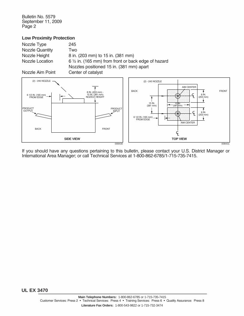
Low Proximity Protection Nozzle Type 245Nozzle Quantity TwoNozzle Height 8 in. (203 mm) to 15 in. (381 mm)Nozzle Location 6 ½ in. (165 mm) from front or back edge of hazard Nozzles positioned 15 in. (381 mm) apartNozzle Aim Point Center of catalyst
If you should have any questions pertaining to this bulletin, please contact your U.S. District Manager or International Area Manager; or call Technical Services at 1-800-862-6785/1-715-735-7415.
CL
CL
CL
(2) - 245 NOZZLE
6 1/2 IN. (165 mm) FROM EDGE
PRODUCT OUTPUT
PRODUCT INPUT
8 IN. (203 mm) - 15 IN. (381 mm)
NOZZLE HEIGHT
BACK FRONT
SIDE VIEW008430
TOP VIEW008431
FRONTBACK
(2) - 245 NOZZLE
15 IN. (381 mm)
6 1/2 IN. (165 mm) FROM EDGE
AIM CENTER
AIM CENTER
8 IN. (203 mm)
8 IN. (203 mm)
15 IN. (381 mm)

This manual is intended for use with ANSUL® R-102™Restaurant Fire Suppression Systems.
Those who install, operate, recharge, or maintain these fire sup-pression systems should read this entire manual. Specific sec-tions will be of particular interest depending upon one’sresponsibilities.
Design, installation, recharge, and maintenance of the systemmust conform to the limitations detailed in this manual and per-formed by an individual who attended an ANSUL training pro-gram and became trained to install, recharge, design, and main-tain the ANSUL system.
Fire suppression systems are mechanical devices. They needperiodic care. Maintenance is a vital step in the performance ofyour fire suppression system. As such it must be performed inaccordance with NFPA 96 (Standard for the Installation ofEquipment for the Removal of Smoke and Grease-Laden Vaporsfrom Commercial Cooking Equipment) and NFPA 17A (Standardon Wet Chemical Extinguishing Systems) by an authorizedANSUL distributor. To provide maximum assurance that the firesuppression system will operate effectively and safely, mainte-nance must be conducted at six-month intervals, or earlier if thesituation dictates. Twelve-year maintenance must include agenttank hydrostatic testing.
ANSUL PART NO. 418087-11
ANSUL, ANSUL AUTOMAN and ANSULEX are trademarks of Tyco International Ltd.or its affiliates.


Indicates revised information.
Indicates change in page sequence.
REVISION INDEXUL EX3470 ULC EX3470 Page 1
7-1-09 REV. 12
8-1-01 5-27 Deleted
10-1-02 4-7 3
10-1-02 6-4 2
10-1-02 9-2 5
10-1-02 9-3 5
10-1-02 9-4 7
10-1-02 9-8 3
10-1-02 9-10 3
10-1-02 9-11 5
10-1-02 9-15 Deleted
10-1-02 9-16 Deleted
4-1-06 3-3 8
4-1-06 3-4 7
4-1-06 4-2 4
4-1-06 4-8 6
4-1-06 4-9 8
4-1-06 4-11 8
4-1-06 5-2.1 5
4-1-06 9-9 4
4-1-06 9-10.2 2
7-1-09 In addition to the revisedtechnical information, theULC Listing file number atthe top of each manualpage has been updated.
7-1-09 T.O.C. – Page 1 10
7-1-09 T.O.C. – Page 2 8
7-1-09 1-1 6
7-1-09 1-2 6
7-1-09 1-3 New
7-1-09 1-4 New
7-1-09 2-1 4
7-1-09 2-2 5
7-1-09 3-1 6
7-1-09 3-2 6
7-1-09 3-5 8
7-1-09 3-6 7
7-1-09 3-7 6
7-1-09 3-8 8
7-1-09 3-9 5
7-1-09 3-10 4
7-1-09 3-11 1
7-1-09 3-12 1
7-1-09 4-1 8
7-1-09 4-3 5
7-1-09 4-4 7
7-1-09 4-5 5
7-1-09 4-6 7
7-1-09 4-10 7
7-1-09 4-12 6
7-1-09 4-13 8
7-1-09 4-14 6
7-1-09 4-15 5
7-1-09 4-16 7
7-1-09 4-17 6
7-1-09 4-18 7
DATE PAGE REV. NO. DATE PAGE REV. NO.

Indicates revised information.
Indicates change in page sequence.
REVISION INDEXUL EX3470 ULC EX3470 Page 2REV. 6 7-1-09
7-1-09 4-19 4
7-1-09 4-20 5
7-1-09 4-21 4
7-1-09 4-22 5
7-1-09 4-23 8
7-1-09 4-24 7
7-1-09 4-25 7
7-1-09 4-26 6
7-1-09 4-27 5
7-1-09 4-28 6
7-1-09 4-29 6
7-1-09 4-30 4
7-1-09 4-31 7
7-1-09 4-32 7
7-1-09 4-33 6
7-1-09 4-34 8
7-1-09 4-34.1 1
7-1-09 4-34.2 1
7-1-09 4-34.3 New
7-1-09 4-34.4 New
7-1-09 4-35 6
7-1-09 4-36 5
7-1-09 4-37 5
7-1-09 4-38 8
7-1-09 4-39 7
7-1-09 4-40 6
7-1-09 4-41 6
7-1-09 4-42 7
7-1-09 4-43 6
7-1-09 4-43.1 New
7-1-09 4-43.2 New
7-1-09 4-43.3 New
7-1-09 4-43.4 New
7-1-09 4-44 6
7-1-09 4-45 4
7-1-09 4-46 6
7-1-09 4-47 5
7-1-09 4-48 6
7-1-09 4-49 5
7-1-09 4-50 5
7-1-09 4-51 5
7-1-09 4-52 4
7-1-09 4-53 4
7-1-09 4-54 5
7-1-09 4-55 4
7-1-09 4-56 4
7-1-09 4-57 2
7-1-09 4-58 2
7-1-09 4-59 2
7-1-09 4-60 2
7-1-09 4-61 New
7-1-09 4-62 New
7-1-09 5-1 7
7-1-09 5-2 5
DATE PAGE REV. NO. DATE PAGE REV. NO.

Indicates revised information.
Indicates change in page sequence.
REVISION INDEXUL EX3470 ULC EX3470 Page 3
7-1-09 REV. 4
7-1-09 5-3 3
7-1-09 5-4 5
7-1-09 5-5 5
7-1-09 5-6 4
7-1-09 5-7 6
7-1-09 5-7.1 New
7-1-09 5-7.2 New
7-1-09 5-7.3 New
7-1-09 5-7.4 New
7-1-09 5-8 3
7-1-09 5-9 2
7-1-09 5-10 3
7-1-09 5-11 3
7-1-09 5-12 4
7-1-09 5-13 3
7-1-09 5-14 3
7-1-09 5-15 4
7-1-09 5-16 3
7-1-09 5-17 4
7-1-09 5-17.1 New
7-1-09 5-17.2 New
7-1-09 5-17.3 New
7-1-09 5-17.4 New
7-1-09 5-17.5 New
7-1-09 5-17.6 New
7-1-09 5-17.7 New
7-1-09 5-17.8 New
7-1-09 5-17.9 New
7-1-09 5-17.10 New
7-1-09 5-17.11 New
7-1-09 5-17.12 New
7-1-09 5-18 6
7-1-09 5-19 5
7-1-09 5-20 3
7-1-09 5-20.1 New
7-1-09 5-20.2 New
7-1-09 5-20.3 New
7-1-09 5-20.4 New
7-1-09 5-21 4
7-1-09 5-22 4
7-1-09 5-23 Deleted
7-1-09 5-24 Deleted
7-1-09 5-25 Deleted
7-1-09 5-26 Deleted
7-1-09 6-1 3
7-1-09 6-2 3
7-1-09 6-3 4
7-1-09 7-2 6
7-1-09 7-3 5
7-1-09 7-4 3
7-1-09 8-1 8
7-1-09 8-2 4
7-1-09 8-3 5
7-1-09 8-4 6
DATE PAGE REV. NO. DATE PAGE REV. NO.

REVISION INDEXUL EX3470 ULC EX3470 Page 4REV. 0 7-1-09
Indicates revised information.
Indicates change in page sequence.
7-1-09 8-5 5
7-1-09 8-6 5
7-1-09 8-7 5
7-1-09 8-8 2
7-1-09 8-9 New
7-1-09 8-10 New
7-1-09 9-1 6
7-1-09 9-5 6
7-1-09 9-6 7
7-1-09 9-6.1 5
7-1-09 9-6.2 3
7-1-09 9-7 4
7-1-09 9-10.1 4
7-1-09 9-12 4
7-1-09 9-13 New
7-1-09 9-14 New
DATE PAGE REV. NO. DATE PAGE REV. NO.

SECTION PAGES
I. GENERAL INFORMATION 1-1 – 1-4
DESIGN AND APPLICATION 1-1
UL LISTING 1-1
SYSTEM APPROVALS 1-1
DEFINITION OF TERMS 1-1 – 1-3
II. SYSTEM DESCRIPTION 2-1 – 2-2
TOTAL SYSTEM 2-1Single-Tank 2-1Double-Tank 2-1Three-Tank 2-2Multiple-Tank 2-2
III. SYSTEM COMPONENTS 3-1 – 3-12
EXTINGUISHING AGENT 3-1
‘‘ANSUL AUTOMAN’’ REGULATED 3-1RELEASE ASSEMBLY(MECHANICAL)
‘‘ANSUL AUTOMAN’’ REGULATED 3-1RELEASE ASSEMBLY(ELECTRICAL)
REMOTE MECHANICAL RELEASE 3-2
SINGLE TANK ENCLOSURE 3-2ASSEMBLY
RED PAINTED BRACKET ASSEMBLY 3-2
REGULATED ACTUATOR 3-2ASSEMBLY
AGENT TANK ASSEMBLY 3-3
OEM RELEASE/BRACKET 3-3ASSEMBLY (FOR OEMIN-CABINET USE ONLY)
OEM REGULATED ACTUATOR 3-3ASSEMBLY
TWO TANK ENCLOSURE ASSEMBLY 3-3
24 VDC REGULATED RELEASE 3-4ASSEMBLY
ADDITIONAL SHIPPING ASSEMBLY 3-4
GAS CARTRIDGES 3-5
NOZZLES 3-5
SILICONE LUBRICANT 3-5
SWIVEL ADAPTOR 3-6
RUBBER BLOW-OFF CAP 3-6
CB METAL BLOW-OFF CAP 3-6
CONDUIT OFFSET ASSEMBLY 3-6
‘‘QUIK-SEAL’’ ADAPTOR 3-6
‘‘COMPRESSION-SEAL’’ ADAPTOR 3-7
‘‘HOOD SEAL’’ ADAPTOR 3-7ASSEMBLY
REDUCING COUPLING 3-7
COCKING LEVER/LOCK BAR 3-7
DETECTORS 3-8
PULLEY ELBOWS 3-8
SECTION PAGES
III. SYSTEM COMPONENTS 3-1 – 3-12(Continued)
PULLEY TEE 3-8
STAINLESS STEEL CABLE 3-8REMOTE MANUAL PULL STATION 3-9FLEXIBLE CONDUIT 3-9MECHANICAL GAS VALVES 3-9ELECTRICAL GAS VALVES 3-10MANUAL RESET RELAY 3-10ELECTRICAL SWITCHES 3-10ALARM INITIATING SWITCH 3-11REGULATOR TEST KIT 3-11FUSIBLE LINK 3-11MAXIMUM REGISTERING 3-11THERMOMETERHOSE/GROMMET PACKAGE 3-11IN-LINE BURST DISC ASSEMBLY 3-12(MANIFOLDED SYSTEMS ONLY)1/4 IN. CHECK VALVE 3-12NOZZLE AIMING DEVICE 3-12STAINLESS STEEL ACTUATOR HOSE 3-12AGENT DISTRIBUTION HOSE AND 3-12RESTRAINING CABLE KIT
IV. SYSTEM DESIGN 4-1 – 4-62
NOZZLE PLACEMENT 4-1 – 4-31REQUIREMENTS
Duct Protection 4-1 – 4-3Transition Protection 4-4Electrostatic Precipitator 4-4Protection
Plenum Protection 4-5 – 4-6Appliance Protection
Fryer – Single Nozzle Protection 4-7 – 4-9Multiple Nozzle Fryer Protection – 4-10 – 4-12Tilt Skillet/Braising Pan 4-12
Range Protection 4-13 – 4-17Griddle Protection 4-18 – 4-21Chain Broiler Protection 4-22Horizontal Chain Broiler Protection 4-22Overhead Chain Broiler Protection 4-22 – 4-23Upright/Salamander Broiler 4-23Protection
Gas-Radiant/Electric Char-Broiler 4-24Protection
Lava-Rock (Ceramic) Char-Broiler 4-25Protection
Natural Charcoal Broiler Protection 4-25Alternate Ceramic/Natural 4-26Charcoal Char-Broiler Protection
Wood Fueled Char-Broiler Protection 4-26Wok Protection 4-27Nozzle Application Chart 4-28 – 4-31Specific Application by Model 4-32 – 4-42Overlapping Nozzle Coverage 4-43 – 4-46
TABLE OF CONTENTSUL EX3470 ULC EX3470 Page 1
7-1-09 REV. 10

TABLE OF CONTENTSUL EX3470 ULC EX3470 Page 2REV. 8 7-1-09
SECTION PAGES
IV. SYSTEM DESIGN (Continued) 4-1 – 4-62
TANK AND CARTRIDGE 4-47REQUIREMENTS
ACTUATION AND EXPELLANT 4-47 – 4-49GAS LINE REQUIREMENTSDISTRIBUTION PIPING 4-49 – 4-56REQUIREMENTS
General Piping Requirements 4-49Supply and Branch Line 4-50 – 4-51Identification
1.5 Gallon System 4-523.0 Gallon System 4-536.0 Gallon Manifolded System 4-54 – 4-559.0 Gallon System 4-56
DETECTION SYSTEM 4-57 – 4-58REQUIREMENTSDetector Identification 4-57Detector/Pulley Elbow Quantity 4-57Detector Placement Requirements 4-57 – 4-58Detection Line Requirements 4-58Fusible Link Selection 4-58
MANUAL PULL STATION 4-59REQUIREMENTS
MECHANICAL GAS VALVE 4-59 – 4-60REQUIREMENTS
ELECTRICAL GAS VALVE 4-60REQUIREMENTSApprovals 4-60
ALARM INITIATING SWITCH 4-60REQUIREMENTS
ELECTRICAL SWITCH 4-60 – 4-61REQUIREMENTS
V. INSTALLATION INSTRUCTIONS 5-1 – 5-22
MOUNTING THE COMPONENTS 5-1 – 5-2.1
INSTALLING THE ACTUATION 5-3 – 5-6AND EXPELLANT GAS LINES
INSTALLING THE DISTRIBUTION 5-7PIPING
INSTALLING THE AGENT 5-7.1 – 5-7.3DISTRIBUTION HOSE (FORCASTERED/MOVEABLE EQUIPMENT)
INSTALLING THE DETECTION 5-8 – 5-11SYSTEM
‘‘Scissors’’ Style Linkage Installation 5-8 – 5-11
INSTALLING REMOTE MANUAL 5-12 – 5-13PULL STATION
General Installation Requirements 5-12Installation for Remote Manual Pull 5-12 – 5-13Station Utilizing EMT Conduit Only
INSTALLING MECHANICAL 5-13 – 5-17GAS VALVE
INSTALLATION REMOTE MANUAL 5-17 – 5-17.11PULL STATION OR MECHANICALGAS VALVE UTILIZINGFLEXIBLE CONDUIT
SECTION PAGES
V. INSTALLATION INSTRUCTIONS 5-1 – 5-22(Continued)
INSTALLING ELECTRICAL 5-18GAS VALVE
INSTALLING ELECTRICAL 5-19 – 5-20SWITCHES
INSTALLING ALARM 5-20INITIATING SWITCH
ELECTRICAL SWITCH 5-20.1 – 5-20.3REQUIREMENTS
WIRING 24 VDC REGULATED 5-21RELEASE ASSEMBLY
VI. TESTING AND PLACING IN SERVICE 6-1 – 6-4
TESTING MANUAL PULL STATION 6-1
TESTING MECHANICAL GAS 6-1VALVES
TESTING ELECTRICAL GAS 6-2VALVES
TESTING ELECTRIC SWITCH 6-2
TESTING DETECTION SYSTEM 6-3
VII. RECHARGE AND RESETTING 7-1 – 7-4PROCEDURES
CLEANUP PROCEDURES 7-1
RECHARGE 7-1 – 7-3
RESETTING 7-3 – 7-4
REPLACEMENT CARTRIDGE 7-4
VIII. MAINTENANCE EXAMINATION 8-1 – 8-10
SEMI-ANNUAL MAINTENANCE 8-1 – 8-4EXAMINATION
ANNUAL MAINTENANCE 8-5EXAMINATION
12-YEAR MAINTENANCE 8-5 – 8-9EXAMINATION
IX. APPENDIX 9-1 – 9-14
SYSTEM SELECTION GUIDE 9-1 – 9-4
SYSTEM COMPONENT INDEX 9-5 – 9-6.2
PARTS LISTS 9-7 – 9-10.2
MULTIPLE NOZZLE FRYER 9-11PROTECTION CALCULATIONEXAMPLES
WIRING DIAGRAM 9-12 – 9-13
SECTION I – GENERAL INFORMATIONUL EX3470 ULC EX3470 Page 1-1
7-1-09 REV. 6
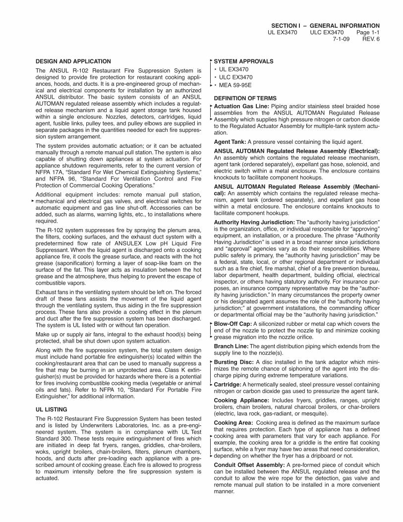
DESIGN AND APPLICATION
The ANSUL R-102 Restaurant Fire Suppression System isdesigned to provide fire protection for restaurant cooking appli-ances, hoods, and ducts. It is a pre-engineered group of mechan-ical and electrical components for installation by an authorizedANSUL distributor. The basic system consists of an ANSULAUTOMAN regulated release assembly which includes a regulat-ed release mechanism and a liquid agent storage tank housedwithin a single enclosure. Nozzles, detectors, cartridges, liquidagent, fusible links, pulley tees, and pulley elbows are supplied inseparate packages in the quantities needed for each fire suppres-sion system arrangement.
The system provides automatic actuation; or it can be actuatedmanually through a remote manual pull station. The system is alsocapable of shutting down appliances at system actuation. Forappliance shutdown requirements, refer to the current version ofNFPA 17A, “Standard For Wet Chemical Extinguishing Systems,”and NFPA 96, “Standard For Ventilation Control and FireProtection of Commercial Cooking Operations.”
Additional equipment includes: remote manual pull station,mechanical and electrical gas valves, and electrical switches forautomatic equipment and gas line shut-off. Accessories can beadded, such as alarms, warning lights, etc., to installations whererequired.
The R-102 system suppresses fire by spraying the plenum area,the filters, cooking surfaces, and the exhaust duct system with apredetermined flow rate of ANSULEX Low pH Liquid FireSuppressant. When the liquid agent is discharged onto a cookingappliance fire, it cools the grease surface, and reacts with the hotgrease (saponification) forming a layer of soap-like foam on thesurface of the fat. This layer acts as insulation between the hotgrease and the atmosphere, thus helping to prevent the escape ofcombustible vapors.
Exhaust fans in the ventilating system should be left on.The forceddraft of these fans assists the movement of the liquid agentthrough the ventilating system, thus aiding in the fire suppressionprocess. These fans also provide a cooling effect in the plenumand duct after the fire suppression system has been discharged.The system is UL listed with or without fan operation.
Make up or supply air fans, integral to the exhaust hood(s) beingprotected, shall be shut down upon system actuation.
Along with the fire suppression system, the total system designmust include hand portable fire extinguisher(s) located within thecooking/restaurant area that can be used to manually suppress afire that may be burning in an unprotected area. Class K extin-guisher(s) must be provided for hazards where there is a potentialfor fires involving combustible cooking media (vegetable or animaloils and fats). Refer to NFPA 10, “Standard For Portable FireExtinguisher,” for additional information.
UL LISTING
The R-102 Restaurant Fire Suppression System has been testedand is listed by Underwriters Laboratories, Inc. as a pre-engi-neered system. The system is in compliance with UL TestStandard 300. These tests require extinguishment of fires whichare initiated in deep fat fryers, ranges, griddles, char-broilers,woks, upright broilers, chain-broilers, filters, plenum chambers,hoods, and ducts after pre-loading each appliance with a pre-scribed amount of cooking grease. Each fire is allowed to progressto maximum intensity before the fire suppression system isactuated.
SYSTEM APPROVALS• UL EX3470• ULC EX3470• MEA 59-95E
DEFINITION OF TERMSActuation Gas Line: Piping and/or stainless steel braided hoseassemblies from the ANSUL AUTOMAN Regulated ReleaseAssembly which supplies high pressure nitrogen or carbon dioxideto the Regulated Actuator Assembly for multiple-tank system actu-ation.
Agent Tank: A pressure vessel containing the liquid agent.
ANSUL AUTOMAN Regulated Release Assembly (Electrical):An assembly which contains the regulated release mechanism,agent tank (ordered separately), expellant gas hose, solenoid, andelectric switch within a metal enclosure. The enclosure containsknockouts to facilitate component hookups.
ANSUL AUTOMAN Regulated Release Assembly (Mechani-cal): An assembly which contains the regulated release mecha-nism, agent tank (ordered separately), and expellant gas hosewithin a metal enclosure. The enclosure contains knockouts tofacilitate component hookups.
Authority Having Jurisdiction: The ‘‘authority having jurisdiction’’is the organization, office, or individual responsible for ‘‘approving’’equipment, an installation, or a procedure. The phrase ‘‘AuthorityHaving Jurisdiction’’ is used in a broad manner since jurisdictionsand ‘‘approval’’ agencies vary as do their responsibilities. Wherepublic safety is primary, the ‘‘authority having jurisdiction’’ may bea federal, state, local, or other regional department or individualsuch as a fire chief, fire marshal, chief of a fire prevention bureau,labor department, health department, building official, electricalinspector, or others having statutory authority. For insurance pur-poses, an insurance company representative may be the ‘‘author-ity having jurisdiction.’’ In many circumstances the property owneror his designated agent assumes the role of the ‘‘authority havingjurisdiction;’’ at government installations, the commanding officeror departmental official may be the ‘‘authority having jurisdiction.’’
Blow-Off Cap: A siliconized rubber or metal cap which covers theend of the nozzle to protect the nozzle tip and minimize cookinggrease migration into the nozzle orifice.
Branch Line: The agent distribution piping which extends from thesupply line to the nozzle(s).
Bursting Disc: A disc installed in the tank adaptor which mini-mizes the remote chance of siphoning of the agent into the dis-charge piping during extreme temperature variations.
Cartridge: A hermetically sealed, steel pressure vessel containingnitrogen or carbon dioxide gas used to pressurize the agent tank.
Cooking Appliance: Includes fryers, griddles, ranges, uprightbroilers, chain broilers, natural charcoal broilers, or char-broilers(electric, lava rock, gas-radiant, or mesquite).
Cooking Area: Cooking area is defined as the maximum surfacethat requires protection. Each type of appliance has a definedcooking area with parameters that vary for each appliance. Forexample, the cooking area for a griddle is the entire flat cookingsurface, while a fryer may have two areas that need consideration,depending on whether the fryer has a dripboard or not.
Conduit Offset Assembly: A pre-formed piece of conduit whichcan be installed between the ANSUL regulated release and theconduit to allow the wire rope for the detection, gas valve andremote manual pull station to be installed in a more convenientmanner.

SECTION I – GENERAL INFORMATIONUL EX3470 ULC EX3470 Page 1-2REV. 6 7-1-09
DEFINITION OF TERMS (Continued)
Depth: When referring to depth as a linear dimension, it is thehorizontal dimension measured from front to back of the applianceor plenum.
Detector: A device which includes the detector bracket, detectorlinkage, and fusible link used for automatic operation of the firesuppression system.
Detector Linkage: A device used to support the fusible link.
Discharge Hose Assembly: An agent distribution hose to beused with castered cooking appliances with castered supports toallow the movement of the appliance for service or cleaning pur-poses.
Distribution Piping: Piping which delivers the extinguishing agentfrom the tank to each discharge nozzle. See also Supply or Branchlines.
Ducts (or Duct System): A continuous passageway for the trans-mission of air and vapors which, in addition to the containmentcomponents themselves, may include duct fittings, dampers, ductfilters, duct transitions, in-line or end-duct pollution control units(PCUs), and/or other items or air handling equipment.
Electrostatic Precipitator: A device used to aid in the cleaning ofthe exhaust air. This device is normally installed at or near thebase of the ventilation duct or may be included as an integral partof a pollution control unit (PCU).
Expellant Gas Line: Piping and/or hose which supplies the nitro-gen or carbon dioxide gas from the regulated release assembly/regulated actuator assembly to each agent tank.
Flexible Conduit: A flexible means to route stainless steel cablefrom the ANSUL AUTOMAN Regulated Release to a manual pullstation or mechanical gas valve.
Flow Number: Term used in system design to describe the flowcapacity of each nozzle used to determine the quantity of tanksneeded to cover a certain group of hazards.
Fusible Links: A fixed temperature heat detecting deviceemployed to restrain the operation of a mechanical control until itsdesigned temperature is reached, allowing separation of the linkand system operation.
Gas Valve: An electrically or mechanically operated device usedto shut off the gas supply to the cooking equipment when the sys-tem is actuated.
Gas Valve Air Cylinder: An air cylinder, located in the releasemechanism, which operates pneumatically to mechanicallyunlatch a mechanical gas valve actuator, causing the gas valve toclose upon system actuation.
High Proximity: Indicates a distance (vertically) between the noz-zle tip and the surface of the appliance being protected.
Hood: A device provided for cooking appliances to direct and cap-ture grease-laden vapors and exhaust gases from cooking appli-ances. It shall be constructed in a manner which meets therequirements of NFPA 96.
Liquid Agent: A potassium-based solution used for the knock-down and suppression of fire.
Low Proximity: Indicates a distance (vertically) between the noz-zle tip and the surface of the appliance being protected.
Maximum Length of Cooking Appliance: The maximum dimen-sion, on any side, which may be protected by one nozzle.
Maximum Piping: Specified length of piping and number of fit-tings which must not be exceeded for each system.
Medium Proximity: Indicates a distance (vertically) between thenozzle tip and the surface of the appliance being protected.
Minimum Piping: Minimum length of distribution piping requiredbetween the agent tank outlet and any nozzle protecting a griddle,range, or fryer.
Nozzle: A device designed to deliver the liquid agent with a spe-cific flow rate and stream pattern.
Overlapping Protection: When discharge nozzles are spacedequally apart over one or more appliances requiring protection.Nozzles used in this manner provide area protection of eligibleappliances within the protected area.Two types of overlapping pro-tection is available: full hood continuous protection and group pro-tection. Overlapping protection is in addition to appliance specificcoverages.
Plenum: The space enclosed by the filters and the portion of thehood above the filters.
Pre-engineered System: NFPA 17A defines a pre-engineeredsystem as one which has “…predetermined flow rates, nozzlepressures, and quantities of liquid agent.” The R-102 system, asprescribed by UL (Underwriter’s Laboratories), has specific pipesizes, maximum and minimum pipe lengths and numbers of fit-tings, and number and types of nozzles. The hazards protected bythis system are also specifically limited as to type and size by ULbased upon actual fire tests. All limitations on hazards that can beprotected and piping and nozzle configurations are contained inthe R-102 installation and maintenance manual which is part ofthe UL listing.
Pulley Elbow: A device used to change the direction of the wirerope which runs between: the regulated release mechanism andthe detectors, the regulated release mechanism and the mechan-ical gas valve, and/or the regulated release mechanism and theremote manual pull station.
Pulley Tee: A device used to change the direction of two wireropes which run from a regulated release or a regulated actuatorto two remote manual pull stations, or from two regulated releasesor regulated actuators to a single mechanical gas valve or fromone regulated release or regulated actuator to two gas valves.
Regulated Actuator Assembly: An assembly which contains theregulator, pneumatic actuator, agent tank, and expellant gas hosewithin a metal enclosure.This assembly is used to pressurize addi-tional agent tanks in a multiple tank system.
Regulated Release Mechanism: An enclosed device within theANSUL AUTOMAN regulated release assembly which releasesthe expellant gas, activates alarms, and/or shuts off other deviceswhen signaled automatically by a detector or manually with aremote pull station.
Regulator: A device used to regulate the pressure from the nitro-gen cartridge into the agent tank(s) when the system is actuated.
Remote Manual Pull Station: A device which provides manualactuation of the system from a remote location.
Salamander Broiler: A broiler very similar in design to the uprightbroiler. A salamander broiler is used for general broiling of meatsand fish, toasting, and holding/warming foods. Most contain aremovable grease drip tray.
Series Detector: Any detector located in-line between the regu-lated release assembly and the terminal detector.
Silicone Lubricant: A heat-resistant organic compound used tolubricate O-rings, rubber and mechanical components.
Supply Line: The agent distribution piping which extends from theagent tank outlet and serves as a manifold for the branch lines.
SECTION I – GENERAL INFORMATIONUL EX3470 ULC EX3470 Page 1-3
7-1-09 REV. 0
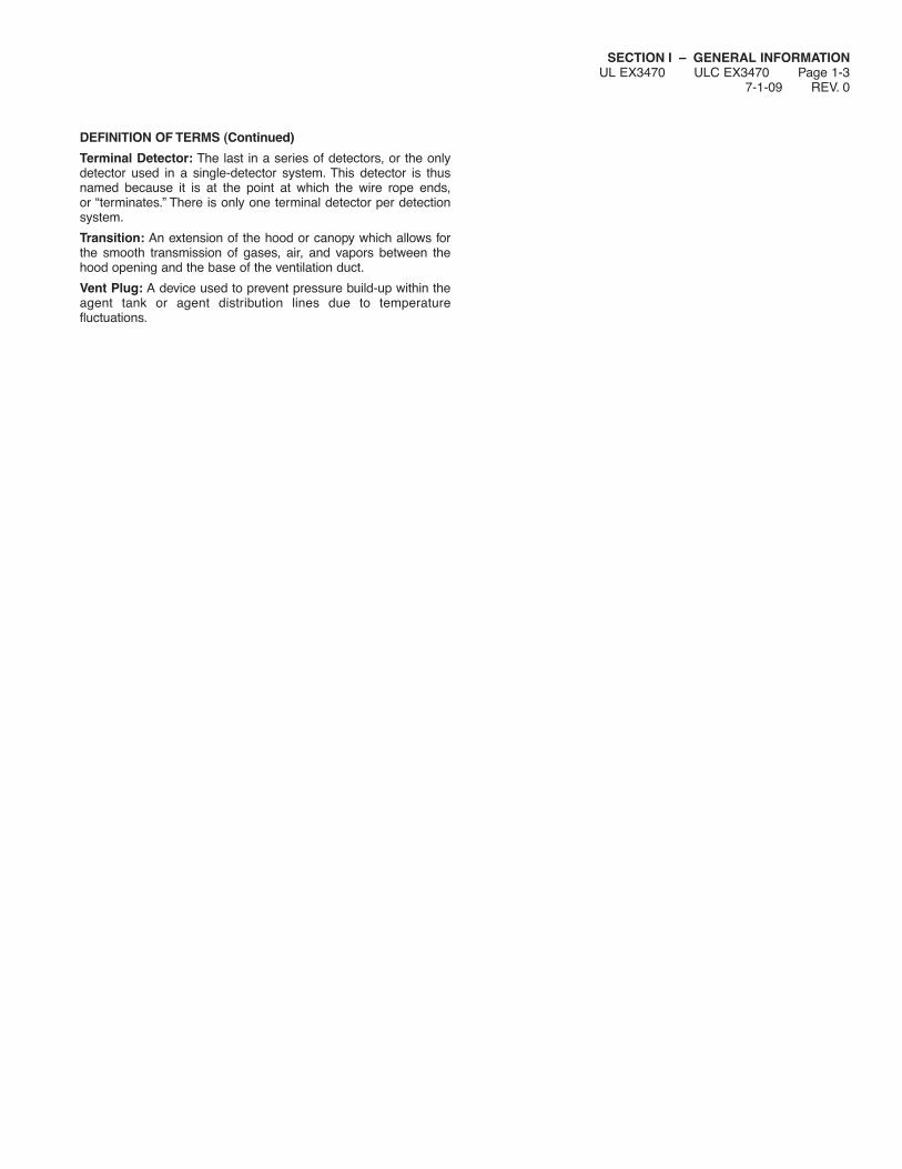
DEFINITION OF TERMS (Continued)
Terminal Detector: The last in a series of detectors, or the onlydetector used in a single-detector system. This detector is thusnamed because it is at the point at which the wire rope ends,or ‘‘terminates.’’ There is only one terminal detector per detectionsystem.
Transition: An extension of the hood or canopy which allows forthe smooth transmission of gases, air, and vapors between thehood opening and the base of the ventilation duct.
Vent Plug: A device used to prevent pressure build-up within theagent tank or agent distribution lines due to temperaturefluctuations.

SECTION I – GENERAL INFORMATIONUL EX3470 ULC EX3470 Page 1-4REV. 0 7-1-09
NOTES:

SECTION II – SYSTEM DESCRIPTIONUL EX3470 ULC EX3470 Page 2-1
7-1-09 REV. 4
TOTAL SYSTEM
There are four types of R-102 Restaurant Fire SuppressionSystems:
1. Single-tank System
2. Double-tank System
3. Three-tank System (1 Cartridge)
4. Multiple Tank System (Three Tanks or More – MultipleCartridges)
The type of system required for the particular installation will bedetermined through the guidelines covered in “System Design.”Additional equipment which may be required to complete the sys-tem design is explained in the “System Components” section.Additional devices covered are: remote manual pull stations,mechanical and electrical gas shut-off valves, electrical switches,and pressure switches.
Single-Tank System
The R-102 single-tank system is available with a stainless steelenclosure and consists of:
1. ANSUL AUTOMAN Regulated Release Assembly (Electricalor Mechanical)
2. Nitrogen Cartridge and/or Carbon Dioxide Cartridge
3. ANSULEX Low pH Liquid Fire Suppressant
4. Discharge Nozzles
5. Detection Components
6. Additional Devices (As Required)
The regulated release assembly contains the regulated releasemechanism, agent tank, expellant gas hose for agent tank hookup,and enclosure knockouts to facilitate installing detection systemand additional equipment. Refer to “System Components” sectionfor individual component descriptions.
FIGURE 1000133
Double-Tank System
The R-102 double-tank system is available with stainless steelenclosures and consists of:
1. ANSUL AUTOMAN Regulated Release Assembly (Electricalor Mechanical)
2. Nitrogen Cartridge and/or Carbon Dioxide Cartridge
3. ANSULEX Low pH Liquid Fire Suppressant
4. Enclosure or Bracket Assembly
5. Discharge Nozzles
6. Detection Components
7. Additional Devices (As Required)
The regulated release assembly contains the regulated releasemechanism, agent tank, expellant gas hose for agent tank hookup,and enclosure knockouts to facilitate installing expellant piping,detection system, and additional equipment.
The enclosure or bracket assembly is mounted separately butwithin the guidelines of the regulated release assembly expellantgas piping requirements to ensure simultaneous actuation of thesystem. Refer to “System Components” section for individual com-ponent descriptions.
FIGURE 2008321

SECTION II – SYSTEM DESCRIPTIONUL EX3470 ULC EX3470 Page 2-2REV. 5 7-1-09
TOTAL SYSTEM (Continued)
Three-Tank System (1 Cartridge with Three (3) 3.0 Gal TanksONLY)
The R-102 three-tank system is available with stainless steelenclosures and consists of:
1. ANSUL AUTOMAN Regulated Release Assembly (Electricalor Mechanical)
2. Double Tank Enclosure Assembly
3. Nitrogen Cartridge
4. ANSULEX Low pH Liquid Fire Suppressant
5. Discharge Nozzles
6. Detection Components
7. Additional Devices (As Required)
The regulated release assembly contains the regulated releasemechanism, agent tank, expellant gas hose for agent tank hookup,and enclosure knockouts to facilitate installing expellant piping,detection system, and additional equipment.
The double tank enclosure assembly is mounted separately butwithin the guidelines of the regulated release assembly expellantgas piping requirements to ensure simultaneous actuation of thesystem. Refer to “System Components” section for individual com-ponent descriptions.
FIGURE 3008322
Multiple Tank System (Three (3) Tanks or More – MultipleCartridges)
The R-102 multiple-tank system is available with stainless steelenclosures and consists of:
1. ANSUL AUTOMAN Regulated Release Assembly(Electrical or Mechanical) or ANSUL AUTOMAN RemoteRelease Assembly(ies)
2. Nitrogen Cartridge(s) and/or Carbon Dioxide Cartridge(s)
3. Regulated Actuator Assembly(ies)
4. ANSULEX Low pH Liquid Fire Suppressant
5. Enclosure or Bracket Assembly(ies)
6. Discharge Nozzles
7. Detection Components
8. Additional Devices (As Required)
The regulated release assembly contains the regulated releasemechanism, agent tank, expellant gas hose for agent tank hookup,and enclosure knockouts to facilitate installing actuation piping,expellant piping, detection system, and additional equipment.
The remote release assembly(ies) is used in large systems ormulti-hood systems to actuate regulated actuator assembly(ies)ONLY. The remote release assembly contains a release mecha-nism (unregulated), with enclosure knockouts to facilitate installingthe actuation piping, expellant piping, detection system, and addi-tional equipment.
Each regulated actuator assembly is mounted separately but with-in the guidelines of the regulated release assembly actuation/expellant gas piping requirements to ensure simultaneous actua-tion of the system. The assembly contains the pneumatic actuator,regulator, agent tank, expellant gas hose for agent tank hookup,and enclosure plugs to facilitate installing expellant piping.
Each enclosure or bracket assembly is mounted separately butwithin the guidelines of the regulated release assembly or regulat-ed actuator assembly expellant gas piping requirements to ensuresimultaneous actuation of the system. Refer to “SystemComponents” section for individual component descriptions.
FIGURE 4008323

SECTION III – SYSTEM COMPONENTSUL EX3470 ULC EX3470 Page 3-1
7-1-09 REV. 6
EXTINGUISHING AGENT
ANSULEX Low pH Liquid Fire Suppressant (1.5 gallon – Part No.79694 or 3.0 gallon – Part No. 79372) is a potassium-based solu-tion designed for fast knock-down and suppression of grease-related fires. The agent is shipped in plastic containers which pro-vide one complete tank charge. (Refer to Section V, Page 5-2.1, formaximum agent fill capacity.) Agent storage life expectancy istwelve years and can be stored at a temperature of –40 °F to 130°F (–40 °C to 54 °C). Note: When installing agent in R-102 sys-tem, temperature range is 32 °F (0 °C) to 130 °F (54 °C). Thedistributor must record the batch numbers and date of shipmentreceipt to be filed with each installation record.“ANSULEX” LOW pH LIQUID FIRE SUPPRESSANT
3.0 GALLON 1.5 GALLONSHIPPING WT. 35 LB (16 kg) SHIPPING WT. 19 LB (9 kg)
000136 000137
FIGURE 1
REGULATED RELEASE ASSEMBLY (MECHANICAL)
The ANSUL AUTOMAN Regulated Mechanical Release Assembly(Part No. 429853) contains the regulated release mechanism,expellant gas hose for agent tank hookup, and enclosure knock-outs to facilitate installing actuation piping; expellant piping; detec-tion system; and additional equipment. This regulated releaseassembly is used in single, double, and multiple-tank systems andmust be mounted to a rigid surface. The release mechanism canbe used to interconnect both the actuation and expellant gas linesas required per system design. The regulator is designed to allowa constant flow of gas into the tank at 110 psi (7.6 bar) when thesystem is actuated. The agent tank must be ordered separately.
In single, double, and multiple-tank systems, the provided expel-lant gas hose connects the agent tank to the bottom outlet of theregulator. In double and multiple-tank system configurations, theback outlet of the regulator is used as an expellant gas feed forone additional tank-enclosure or tank-bracket hookup. The enclo-sure contains the required knockouts to facilitate this connection.If a pressure switch is to be attached to the regulator, additional fit-tings are required.
The tank is mounted within the enclosure. The tank contains anadaptor/tube assembly with a burst disc union. The burst dischelps prevent siphoning of the agent up the pipe due to significanttemperature fluctuations in the area where the tank is located. Thetank is stainless steel and, under normal conditions, requireshydrostatic testing every twelve years.
The detection and additional equipment required per systemdesign are connected to the release mechanism. The enclosurecontains knockouts to facilitate detection and additional hookups.
The system can be actuated automatically or manually. Automaticactuation occurs when a fusible link within the detection systemseparates in a fire condition. Manual actuation of the systemoccurs when personnel pull on the remote manual pull stationpull ring.
“ANSUL AUTOMAN” REGULATED RELEASE ASSEMBLY(MECHANICAL)
FIGURE 2000138
REGULATED RELEASE ASSEMBLY (ELECTRICAL)
The ANSUL AUTOMAN Regulated Electrical Release Assembly(Part No. 429856) is identical to the mechanical version except italso contains a factory installed 120 VAC solenoid and electricalswitch.
The solenoid is used to provide electrical actuation of the releasemechanism. The electric switch is used to protect the solenoid byopening the circuit to the solenoid once the system is fired.Additional electrical switches can be added as required for auto-matic equipment and gas shut-off accessories, as well as initiatingaudible and visual alarms.
“ANSUL AUTOMAN” REGULATED RELEASE ASSEMBLY(ELECTRICAL)*
FIGURE 3000139
* NOTE: ANSUL AUTOMAN Regulated Electrical Release, Part No. 429856, is notintended to be used with electric detection.
NOTE: AGENT TANK MUST BEORDERED SEPARATELYOR SEE PAGE 3-4
REGULATOR
SHIPPING WT. 25 LB (11 kg)
RELEASEMECHANISM
NOTE: AGENT TANK MUST BEORDEREDSEPARATELYOR SEE PAGE 3-4
SOLENOID
SWITCHREGULATOR
SHIPPING WT. 34 LB (15 kg)

SECTION III – SYSTEM COMPONENTSUL EX3470 ULC EX3470 Page 3-2REV. 6 7-1-09
REMOTE MECHANICAL RELEASE
The Remote Mechanical Release, Part No. 433485, is used toactuate up to five (5) R-102 regulated actuators. The remotemechanical release utilizes a 101-10 carbon dioxide cartridge asthe actuation pressure to operate the regulated actuators. Therelease is housed in a stainless steel enclosure.
FIGURE 4007498
SINGLE TANK ENCLOSURE ASSEMBLY
The Single Tank Enclosure Assembly (Part No. 429870) is used indouble and multiple-tank systems and must be mounted to a rigidsurface near the regulated release or regulated actuator assemblyits expellent gas line will be connected to.
The enclosure is designed for mounting either a 1.5 gallon (PartNo. 429864) or a 3.0 gallon tank (Part No. 429862) in a minimumamount of space.
ENCLOSURE ASSEMBLY
FIGURE 5000142
RED PAINTED BRACKET ASSEMBLY
The Bracket Assembly (Part No. 429878) is used in double andmultiple-tank systems and must be mounted to a rigid surface nearthe regulated release assembly or regulated actuator assemblythat its expellant gas line will be connected to.
The tank bracket is constructed of mild steel and painted red. It isdesigned for mounting the tank in a minimum amount of space.The Bracket Assembly can only be utilized with 3.0 gallon tanks(Part No. 429862).
BRACKET ASSEMBLY
FIGURE 6000141
REGULATED ACTUATOR ASSEMBLY
The Regulated Actuator Assembly (Part No. 429850) contains theregulator, pneumatic actuator, expellant gas hose for agent tankhookup, and enclosure knockouts to facilitate installing expellant pip-ing. This assembly is used in multiple-tank systems and must bemounted to a rigid surface.
The regulator contains two outlets 135° apart. One outlet is usedto interconnect the expellant gas hose to the enclosed agent tank.The other outlet connects an expellant gas line to an additionalenclosure or bracket assembly. The regulator is designed to allowa constant flow of nitrogen into each agent tank connected (twotanks maximum) at 110 psi (7.6 bar).
The pneumatic actuator is designed to puncture the expellant gascartridge seal upon receiving pressure from the regulated releaseassembly actuation piping. The enclosure contains a knockout tofacilitate distribution piping hookup.
REGULATED ACTUATOR ASSEMBLY
FIGURE 7000143
MOUNTINGBRACKET
PNEUMATICACTUATORASSEMBLY
NOTE: AGENT TANKMUST BEORDEREDSEPARATELYOR SEE PAGE 3-4
NOTE: AGENT TANK MUSTBE ORDEREDSEPARATELYOR SEE PAGE 3-4
MOUNTINGENCLOSURE
REGULATOR
SHIPPING WT.13 LB (6 kg)
SHIPPING WT. 7 LB (3 kg)
SHIPPING WT.19 LB (9 kg)
RELEASEMECHANISM
SHIPPING WEIGHT:20 LB (9.1 kg)

SECTION III – SYSTEM COMPONENTSUL EX3470 ULC EX3470 Page 3-3
4-1-06 REV. 8
AGENT TANK ASSEMBLY
The agent tank shipping assembly (3-Gallon, Part No. 429862,and 1.5 Gallon, Part No. 429864) consists of a stainless steel tankand an adaptor/tube assembly. The adaptor/tube assembly con-tains a burst disc. The burst disc prevents agent leakage due tosignificant temperature fluctuations in the area where the tank islocated. Under normal conditions, the tank requires hydrostatictesting every twelve years. The date of manufacture is stamped onthe tank nameplate.
The tank is shipped uncharged and must be filled with onlyANSULEX Low pH Liquid Fire Suppressant during installation.
FIGURE 8000140
OEM RELEASE/BRACKET ASSEMBLY(FOR OEM IN-CABINET USE ONLY)
The OEM Regulated Mechanical Release/Bracket Assembly, PartNo. 79493, contains the same regulated release mechanism asthe standard ANSUL AUTOMAN Regulated Release Assembly.The OEM Regulated Electrical Release/Bracket Assembly, PartNo. 418054*, is identical to the mechanical version except it con-tains a factory installed 120 VAC solenoid and electrical switch.These release/bracket assemblies must be installed in a suitableequipment enclosure either horizontally or vertically. They containall the necessary mounting and conduit holes needed to fullyinstall the assembly. The agent tank is installed separately andneed not be bracketed once it is piped and filled. Note: OEMRelease/Bracket Assembly must be installed high enough in cabi-net so that there is sufficient room to install and remove cartridge.*Note: OEM Regulated Electrical Release/Bracket Assembly, Part No. 418054, isnot intended to be used with electric detection.
FIGURE 9000144
OEM REGULATED ACTUATOR ASSEMBLY
The OEM Regulated Actuator Assembly, Part No. 418691,includes the regulator, pneumatic actuator, expellant gas hose andOEM bracket. Also available is an OEM Regulated ActuatorAssembly with all the above mentioned components except for thebracket. This assembly is Part No. 418522.
SHIPPING WT. 4 LB (2 kg)
FIGURE 10002225
TWO TANK ENCLOSURE ASSEMBLY
The Two Tank Enclosure Assembly, Part No. 429872, consists oftwo expellant gas hoses, two grommets, and the mounting enclo-sure. The assembly is used in 9 gallon systems. It can be coupledwith a 3-gallon regulated release assembly or a 3-gallon regulatedactuator assembly to give a total of 9 gallons of agent. Agent tanksmust be ordered separately.
The tank enclosure is designed to mount in a minimum amount ofspace.
SHIPPING WT.26 LBS (12 kg)
FIGURE 11002277
MOUNTINGBRACKET
REGULATOR
RELEASEMECHANISM
SHIPPING WT.10 LB (5 kg)
AGENTTANK
TANK ADAPTOR/TUBE ASSEMBLY
3 GALLONSHIPPING WT.
7 LB (3 kg)
1.5 GALLONSHIPPING WT.
5 LB (2 kg)
SECTION III – SYSTEM COMPONENTSUL EX3470 ULC EX3470 Page 3-4REV. 7 4-1-06
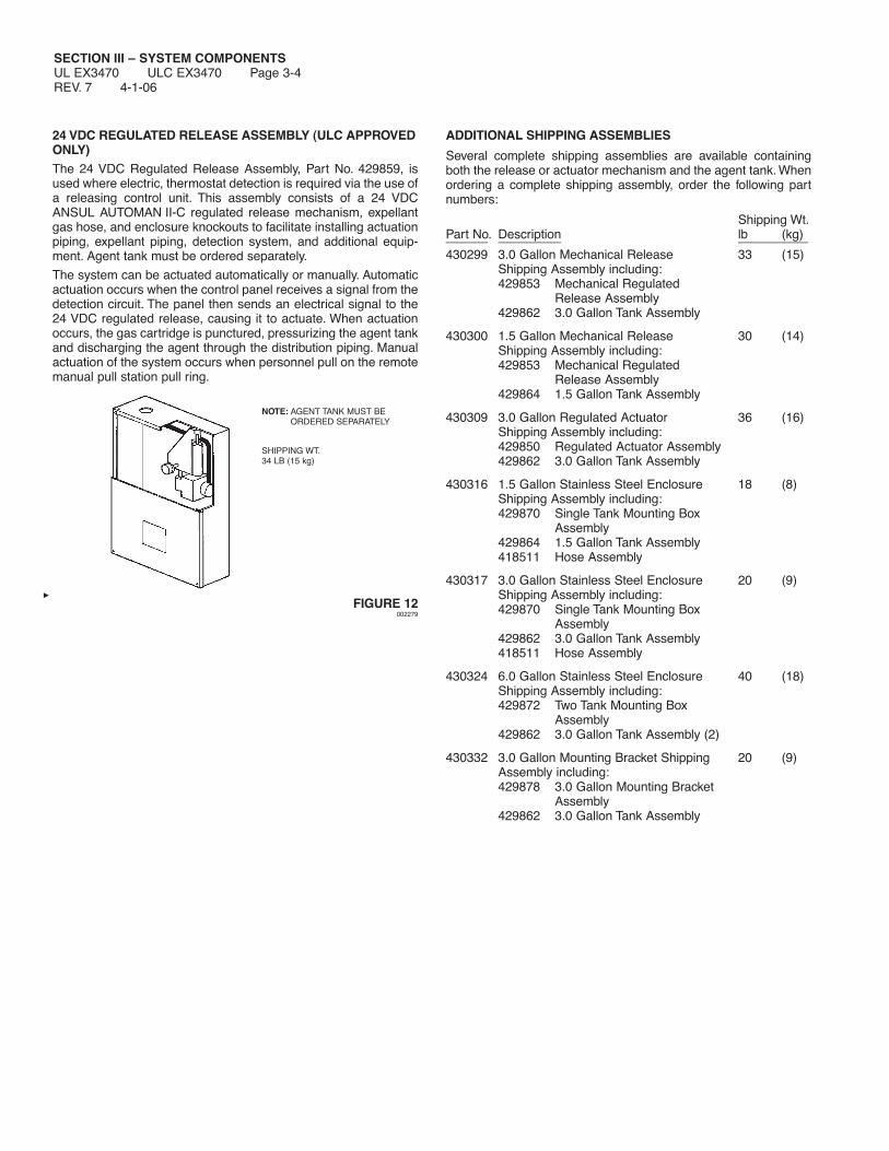
24 VDC REGULATED RELEASE ASSEMBLY (ULC APPROVEDONLY)The 24 VDC Regulated Release Assembly, Part No. 429859, isused where electric, thermostat detection is required via the use ofa releasing control unit. This assembly consists of a 24 VDCANSUL AUTOMAN II-C regulated release mechanism, expellantgas hose, and enclosure knockouts to facilitate installing actuationpiping, expellant piping, detection system, and additional equip-ment. Agent tank must be ordered separately.
The system can be actuated automatically or manually. Automaticactuation occurs when the control panel receives a signal from thedetection circuit. The panel then sends an electrical signal to the24 VDC regulated release, causing it to actuate. When actuationoccurs, the gas cartridge is punctured, pressurizing the agent tankand discharging the agent through the distribution piping. Manualactuation of the system occurs when personnel pull on the remotemanual pull station pull ring.
NOTE: AGENT TANK MUST BEORDERED SEPARATELY
SHIPPING WT.34 LB (15 kg)
FIGURE 12002279
ADDITIONAL SHIPPING ASSEMBLIES
Several complete shipping assemblies are available containingboth the release or actuator mechanism and the agent tank. Whenordering a complete shipping assembly, order the following partnumbers:
Shipping Wt.Part No. Description lb (kg)______ _________ __________430299 3.0 Gallon Mechanical Release 33 (15)
Shipping Assembly including:429853 Mechanical Regulated
Release Assembly429862 3.0 Gallon Tank Assembly
430300 1.5 Gallon Mechanical Release 30 (14)Shipping Assembly including:429853 Mechanical Regulated
Release Assembly429864 1.5 Gallon Tank Assembly
430309 3.0 Gallon Regulated Actuator 36 (16)Shipping Assembly including:429850 Regulated Actuator Assembly429862 3.0 Gallon Tank Assembly
430316 1.5 Gallon Stainless Steel Enclosure 18 (8)Shipping Assembly including:429870 Single Tank Mounting Box
Assembly429864 1.5 Gallon Tank Assembly418511 Hose Assembly
430317 3.0 Gallon Stainless Steel Enclosure 20 (9)Shipping Assembly including:429870 Single Tank Mounting Box
Assembly429862 3.0 Gallon Tank Assembly418511 Hose Assembly
430324 6.0 Gallon Stainless Steel Enclosure 40 (18)Shipping Assembly including:429872 Two Tank Mounting Box
Assembly429862 3.0 Gallon Tank Assembly (2)
430332 3.0 Gallon Mounting Bracket Shipping 20 (9)Assembly including:429878 3.0 Gallon Mounting Bracket
Assembly429862 3.0 Gallon Tank Assembly

SECTION III – SYSTEM COMPONENTSUL EX3470 ULC EX3470 Page 3-5
7-1-09 REV. 8
GAS CARTRIDGES
The R-102 system uses gas cartridges to store nitrogen or carbondioxide expellant gases under pressure until the system is actuat-ed, at which time the cartridge seal is punctured and the releasedgas expels liquid agent from one or more tanks through the dis-charge piping and out the discharge nozzles.
Four nitrogen gas cartridges and three carbon dioxide gas car-tridges are available as shown in Figure 13.
Cartridges noted as TC/DOT are both Transport Canada (TC) andDepartment of Transportation (DOT) approved. Cartridges notedas DOT are Department of Transportation approved only.
Cartridge selection options are provided in Section IV under Tankand Cartridge Requirements.
NITROGEN GAS CARTRIDGES
LT-20-R LT-30-R DOUBLE-TANK LT-A-101-30CARTRIDGE CARTRIDGE CARTRIDGE CARTRIDGE
000145 000146 000147 000148
CARBON DIOXIDE CARTRIDGES
101-10 CARTRIDGE 101-20 CARTRIDGE 101-30 CARTRIDGE000149 000150 000151
FIGURE 13
Additional cartridge shipping assemblies are available forEuropean and Australian requirements.
Cartridge European Australian TC/DOTDescription Part No. Part No. Part No._________ _______ ______ _______LT-20-R 428440 428948 423429LT-30-R 428441 426553 423435Double Tank 428446 426563 423493LT-A-101-30 428442 426555 423491101-10 – CO2 428443 N/A 423439101-20 – CO2 428445 N/A 423441101-30 – CO2 428444 N/A 423443
Note: For 101-10 cartridge, Part No. 15850 is DOT only.
NOZZLES
There are 11 types of discharge nozzles each designed to distrib-ute the liquid agent in a uniform pattern throughout the hazardarea:1. 1W Nozzle 7. 245 Nozzle2. 1N Nozzle 8. 260 Nozzle3. 1/2N Nozzle 9. 290 Nozzle4. 3N Nozzle 10. 2120 Nozzle5. 2W Nozzle 11. 1F Nozzle6. 230 Nozzle
Although these nozzles are similar in appearance and havecertain common parts, the tip of each nozzle is designed for aspecific application and must only be used in those areas. SeeNozzle Application Chart in Section IV – System Design, forindividual nozzle usage.
FIGURE 14000002
Nozzle Identification Chart
Note: See Component Index for nozzle package shipping assem-bly part numbers.
NozzleNozzle Nozzle Nozzle* FlowType Part No. Stamping No. Nozzle Material
1W Nozzle 419336 1W** 1 Chrome-Plated Body1N Nozzle 419335 1N** 1 Chrome-Plated Body1/2N Nozzle 419334 1/2N 1/2 Chrome-Plated Body3N Nozzle 419338 3N 3 Chrome-Plated Body2W Nozzle 419337 2W 2 Chrome-Plated Body230 Nozzle 419339 230 2 Chrome-Plated Body245 Nozzle 419340 245 2 Chrome-Plated Body260 Nozzle 419341 260 2 Chrome-Plated Body290 Nozzle 419342 290 2 Chrome-Plated Body2120 Nozzle 419343 2120 2 Chrome-Plated Body1F Nozzle 419333 1F 1 Chrome-Plated Body
* Nozzle stamping may contain an additional letter indicating a vendor’s code.
**Stainless steel versions are available in the 1W nozzle (Part No. 432527) andthe 1N nozzle (Part No. 435672).
SILICONE LUBRICANT
Dow Corning Compound 111, Part No. 78112, is available in a5.3-ounce tube. Compound has excellent qualities for sealing andlubricating system components.
3/8 – 18 NPTFEMALE THREAD
INTERNAL CUPSTRAINERINSIDE
VENDORCODE(IF PRESENT)NOZZLE
STAMPING
RECESS FORBLOW OFFCAP LOOP3 9/16 IN.
(9 cm)
17 1/4 IN.(43.8 cm)
2 1/2 IN.(6.4 cm)
11 5/8 IN.(29.5 cm)
2 1/2 IN.(6.4 cm)
7 7/8 IN.(20 cm)
4 3/16 IN.(10.6 cm)
12 1/4 IN.(31.1 cm)
11 5/8 IN.(29.5 cm)
2 IN.(5.1 cm)
2 1/2 IN.(6.4 cm)
9 IN.(22.9 cm)
2 1/2 IN.(6.4 cm)
7 7/8 IN.(20 cm)

SECTION III – SYSTEM COMPONENTSUL EX3470 ULC EX3470 Page 3-6REV. 7 7-1-09
SWIVEL ADAPTOR
The Swivel Adaptor Assembly consists of a swivel nut, swivel bodyand swivel ball. All are chrome-plated. The swivel adaptor allowsany nozzle to be rotated approximately 30° in all directions. SwivelAdaptors must be ordered as a Swivel Adaptor ShippingAssembly, Part No. 423572, which contains 25 Swivel Adaptors orPart No. 419385, which contains 9 Swivel Adaptors.
FIGURE 15000003
RUBBER BLOW-OFF CAPS
The Rubber Blow-Off Cap helps keep the orifice of the nozzle freeof grease or other substances that could interfere with agent dis-tribution. A retaining strap attaches the blow-off cap to the nozzle.Rubber Blow-Off Caps must be ordered as a Shipping Assembly,Part No. 77695, which contains 50 blow-off caps, or Part No.77411, which contains 12 blow-off caps.
FIGURE 16000009
CB METAL BLOW-OFF CAP
The CB Metal Blow-off Cap Package, Part No. 433208, is used forall high temperature environments. The metal blow-off cap con-tains a special O-ring placed inside the cap which integrates withthe nozzle to create a seal and to help hold the blow-off cap inposition.
The CB Metal Blow-Off Cap Package, Part No. 433208, contains10 blow-off caps.
Also available is a 10 pack of CB Stainless Steel Blow-Off Caps,Part No. 434707.
A 10 pack of Metal Blow-Off Cap O-rings, Part No. 551530, is alsoavailable.
FIGURE 17007633
CONDUIT OFFSET ASSEMBLY
The conduit offset assembly, Part No. 435961, is used to changedirection of the wire rope on detection, mechanical gas valve, andremote pull station lines. The conduit offset assembly can only beused in the area where the conduit attaches to the regulatedrelease assembly. When using the conduit offset assembly, themaximum number of pulley elbows is still allowed. The ConduitOffset Shipping Assembly, Part No. 436063, consists of 6 conduitoffsets.
FIGURE 18000153
“QUIK-SEAL” ADAPTORThe “Quik-Seal” adaptor is a listed mechanical bulkhead fitting thatproduces a liquid-tight seal around both distribution piping anddetection conduit which runs through restaurant hoods and ducts.The “Quik-Seal” adaptor accepts threaded pipe or conduit. Theadaptor is available for 1/4 in. (Part No. 78196), 3/8 in. (Part No.77285), 1/2 in. (Part No. 77287), or 3/4 in. (Part No. 77289) pipe orconduit sizes. When using with EMT conduit, a conduit connectormust be installed in each end of the adaptor. The “Quik-Seal”Adaptor Shipping Assembly must be ordered as stated below:
ShippingAssembly Hole Size
Size Part No. Qty. Required____ ________ ___ ________1/4 in. 78196 24 3/4 in.3/8 in. 77285 24 1 1/8 in.1/2 in. 77287 24 1 1/8 in.3/4 in. 77289 24 1 3/8 in.
FIGURE 19000154
CONDUITCOUPLING
CONDUITOFFSET
CONDUITCONNECTOR
3/8 – 18 NPTFEMALE THREAD
3/8 – 18 NPTMALE THREAD
30 DEGREEROTATION
STAINLESSSTEEL WIRE
METAL CAP
ADAPTOR BODY
GASKETLOCKWASHER
NUT
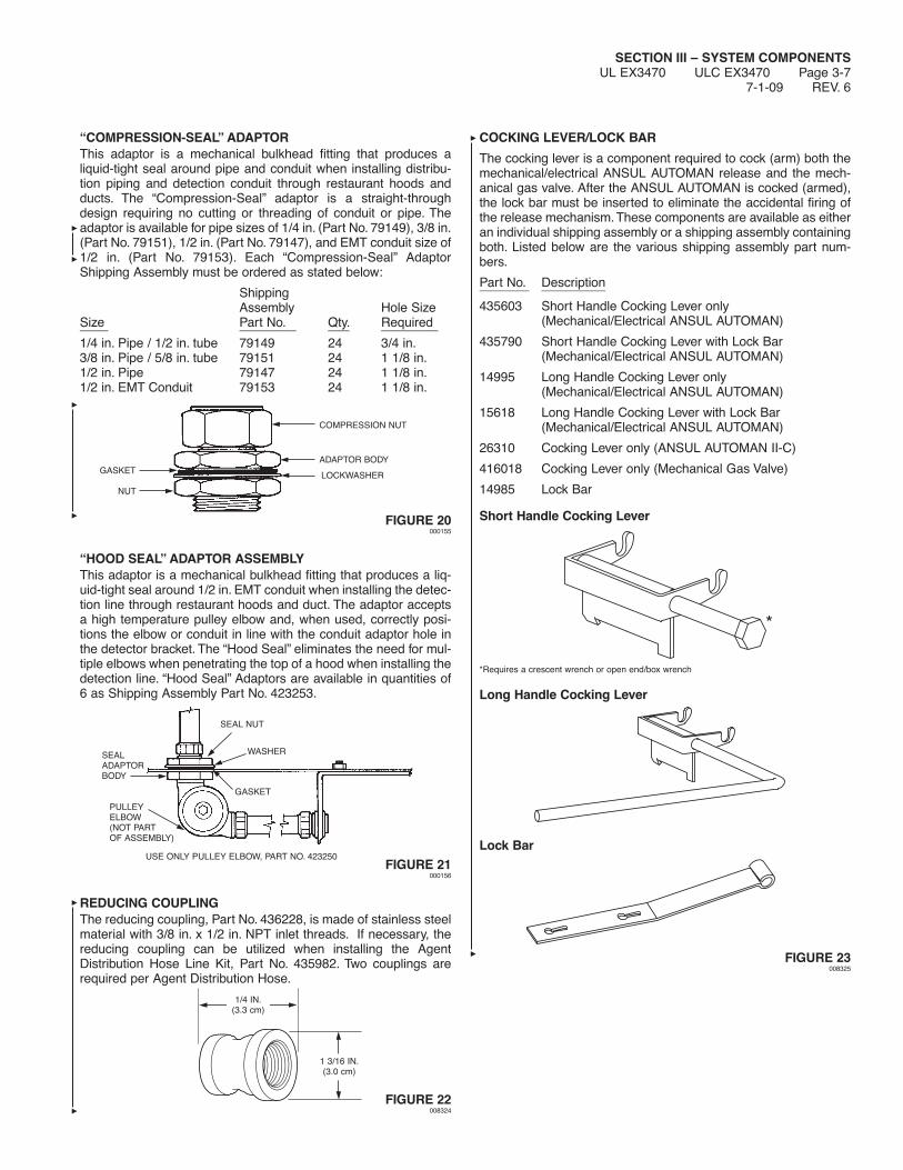
SECTION III – SYSTEM COMPONENTSUL EX3470 ULC EX3470 Page 3-7
7-1-09 REV. 6
“COMPRESSION-SEAL” ADAPTORThis adaptor is a mechanical bulkhead fitting that produces aliquid-tight seal around pipe and conduit when installing distribu-tion piping and detection conduit through restaurant hoods andducts. The “Compression-Seal” adaptor is a straight-throughdesign requiring no cutting or threading of conduit or pipe. Theadaptor is available for pipe sizes of 1/4 in. (Part No. 79149), 3/8 in.(Part No. 79151), 1/2 in. (Part No. 79147), and EMT conduit size of1/2 in. (Part No. 79153). Each “Compression-Seal” AdaptorShipping Assembly must be ordered as stated below:
ShippingAssembly Hole Size
Size Part No. Qty. Required____ ________ ___ ________1/4 in. Pipe / 1/2 in. tube 79149 24 3/4 in.3/8 in. Pipe / 5/8 in. tube 79151 24 1 1/8 in.1/2 in. Pipe 79147 24 1 1/8 in.1/2 in. EMT Conduit 79153 24 1 1/8 in.
FIGURE 20000155
“HOOD SEAL” ADAPTOR ASSEMBLYThis adaptor is a mechanical bulkhead fitting that produces a liq-uid-tight seal around 1/2 in. EMT conduit when installing the detec-tion line through restaurant hoods and duct. The adaptor acceptsa high temperature pulley elbow and, when used, correctly posi-tions the elbow or conduit in line with the conduit adaptor hole inthe detector bracket. The “Hood Seal” eliminates the need for mul-tiple elbows when penetrating the top of a hood when installing thedetection line. “Hood Seal” Adaptors are available in quantities of6 as Shipping Assembly Part No. 423253.
FIGURE 21000156
REDUCING COUPLINGThe reducing coupling, Part No. 436228, is made of stainless steelmaterial with 3/8 in. x 1/2 in. NPT inlet threads. If necessary, thereducing coupling can be utilized when installing the AgentDistribution Hose Line Kit, Part No. 435982. Two couplings arerequired per Agent Distribution Hose.
FIGURE 22008324
COCKING LEVER/LOCK BAR
The cocking lever is a component required to cock (arm) both themechanical/electrical ANSUL AUTOMAN release and the mech-anical gas valve. After the ANSUL AUTOMAN is cocked (armed),the lock bar must be inserted to eliminate the accidental firing ofthe release mechanism.These components are available as eitheran individual shipping assembly or a shipping assembly containingboth. Listed below are the various shipping assembly part num-bers.
Part No. Description_______ _________
435603 Short Handle Cocking Lever only(Mechanical/Electrical ANSUL AUTOMAN)
435790 Short Handle Cocking Lever with Lock Bar(Mechanical/Electrical ANSUL AUTOMAN)
14995 Long Handle Cocking Lever only(Mechanical/Electrical ANSUL AUTOMAN)
15618 Long Handle Cocking Lever with Lock Bar(Mechanical/Electrical ANSUL AUTOMAN)
26310 Cocking Lever only (ANSUL AUTOMAN II-C)
416018 Cocking Lever only (Mechanical Gas Valve)
14985 Lock Bar
Short Handle Cocking Lever
*Requires a crescent wrench or open end/box wrench
Long Handle Cocking Lever
Lock Bar
FIGURE 23008325
*
SEALADAPTORBODY
SEAL NUT
WASHER
PULLEYELBOW(NOT PARTOF ASSEMBLY)
USE ONLY PULLEY ELBOW, PART NO. 423250
GASKET
COMPRESSION NUT
ADAPTOR BODY
LOCKWASHERGASKET
NUT
1/4 IN.(3.3 cm)
1 3/16 IN.(3.0 cm)

SECTION III – SYSTEM COMPONENTSUL EX3470 ULC EX3470 Page 3-8REV. 8 7-1-09
DETECTORS
The detector consists of three basic components: the bracket, link-age, and fusible link. (Fusible links are not included and must beordered separately.) The bracket holds the entire assembly to themounting surface. The linkage is used to support the fusible link.The fusible link is designed to separate at a specific temperatureand release the wire rope, thereby actuating the regulated releasemechanism.
The scissor style detector allows the wire rope to be strung com-pletely through the detection system conduit and brackets first andthe detector linkage assemblies are then clipped on later.
The detector consists of two types of assemblies:
The Terminal Detector (Part No. 435546) includes a test link andis placed last in a series of detectors. This detector is sometimesreferred to as the end-of-line detector and is thus named becauseit is at the point at which the wire rope “terminates,” or is anchoredat the detector bracket. Only one terminal detector is required perdetection system.
The Series Detector (Part No. 435547) is any detector located in-line between the regulated release assembly and the terminaldetector.
When using Part No. 435546 and 435547 detectors, a total of 15detectors can be in one detection system: 14 series detectors, PartNo. 435547 and 1 terminal detector, Part No. 435546.
Note: Series Detector, Part No. 435547, is also available as PartNo. 435548, 25/Pkg.
SCISSOR STYLE – PART NO. 435546 AND 435547
FIGURE 24000159
PULLEY ELBOWS
There are two types of pulley elbows used to change the directionof the wire rope by 90°. ANSUL recommends for temperatures notin excess of 700 °F (371 °C). Part No. 415670 has socket endswith set screws for 1/2 in. conduit, and Part No. 423250 has com-pression ring ends also for 1/2 in. conduit. Pulley elbows must beordered in quantities of 50 as Shipping Assembly Part No. 415671(socket end type) and Part No. 423251 (compression end type).
PART NO. 415670 PART NO. 423250
000160 000161
FIGURE 25
PULLEY TEE
The Pulley Tee (Part No. 427929) is used to change the directionof two wire ropes by 90°. It must be used in areas where the tem-peratures are within the range of 32 °F to 130 °F (0 °C to 54 °C).Pulley tees can be used in mechanical gas valve actuation linesand remote manual pull station lines. Pulley tees cannot be usedwithin a detection line.
FIGURE 26000447
STAINLESS STEEL CABLE
The 1/16 in. stainless steel cable is run from the terminal detector,through conduit, all series detectors and pulley elbows, and intothe regulated release mechanism trip lever. When any fusible linkseparates, the tension on the cable is relaxed, and the trip leveractuates the regulated release mechanism. The cable can also beused for mechanical gas valves and remote manual pull stations.The cable is available in 50 ft (15 m) (Part No. 15821) and 500 ft(152.4 m) (Part No. 79653) lengths.
FUSIBLELINK
BRACKET
LINKAGE

SECTION III – SYSTEM COMPONENTSUL EX3470 ULC EX3470 Page 3-9
7-1-09 REV. 5
REMOTE MANUAL PULL STATION
The remote manual pull station (Part No. 434618 or 435960) ismade out of a molded red composite material. The red colormakes the pull station more readily identifiable as the manualmeans for fire suppression system operation. The pull station iscompatible with the ANSUL Flexible Conduit. The molded manualpull station should be mounted at a point of egress and positionedat a height determined by the authority having jurisdiction. TrimRings, Part No. 427074 (pack of 10), are available.
Part No. 434618 (Without Wire Rope)Part No. 435960 (With 50 ft (15.2 m) of Wire Rope)
FIGURE 27008326
FLEXIBLE CONDUITFlexible conduit allows for quicker installations and the conve-nience of being able to route the cable over, under and aroundobstacles. Flexible conduit can be used as a substitute for stan-dard EMT conduit or can be used with EMT conduit. Flexible con-duit can be used only with the Molded Manual Pull Station, PartNo. 434618, and mechanical gas valve installations. The FlexibleConduit comes in a 500 ft (152.4 m) length, Part No. 434525, ortogether with 500 ft (152.4 m) of wire rope, Part No. 435959.
Also available is a Flexible Conduit Strain Relief (50-pack), PartNo. 435979.
A 50-pack of Flexible Conduit Inserts, Part No. 434347, is alsoavailable.Note: Flexible conduit cannot be used in detection systems.
MECHANICAL GAS VALVESThe mechanical gas valves are designed to shut off the flow of gasto the appliances upon actuation of the regulated release assem-bly. The valves are available in sizes of 3/4 in., 1 in., 1 1/4 in., 1 1/2in., and 2 in. ANSUL style; and 2 1/2 in. and 3 in. ASCO style. Thevalves are rated for natural and LP gas. Both styles are UL Listedand includes the air cylinder, tubing, and fittings, Part No. 15733,for connection to the release mechanism.
Maximum Part OperatingNo. Description Pressure____ _________ ________________55598 3/4 in. Gas Valve (ANSUL) 10 psi (0.69 bar)55601 1 in. Gas Valve (ANSUL) 10 psi (0.69 bar)55604 1 1/4 in. Gas Valve (ANSUL) 10 psi (0.69 bar)55607 1 1/2 in. Gas Valve (ANSUL) 10 psi (0.69 bar)55610 2 in. Gas Valve (ANSUL) 10 psi (0.69 bar)25937 2 1/2 in. Gas Valve (ASCO) 5 psi (0.35 bar)25938 3 in. Gas Valve (ASCO) 5 psi (0.35 bar)
Flow Capacity BTU/HR, at 1 in. P.D.(CFH) 0.64 SP GR
Pipe Size P.D. 1 in. WC 1000 BTU/ft3(inches) 0.64 SP GR Natural Gas______ __________ __________3/4 751 751,0001 1288 1,288,0001 1/4 1718 1,718,0001 1/2 2630 2,630,0002 4616 4,616,0002 1/2 5700 5,800,0003 7100 7,300,000
To calculate gas flow for other than 1 inch p.d.:
New cfh = (cfh at 1 inch) x � new p.d.
To calculate gas flow for other than 0.64 SP GR:
New cfh = (cfh at 0.64) x � 0.64 New SP GR
A B CValve Size in. (mm) in. (mm) in. (mm)________ ____________ __________ ____________3/4 in. 3 3/4 (95.3) 6 3/8 (161.9) 5 1/2 (139.7)1 in. 3 3/4 (95.3) 6 3/8 (161.9) 5 1/2 (139.7)1 1/4 in. 4 7/8 (123.8) 7 3/8 (187.3) 6 3/8 (161.9)1 1/2 in. 4 7/8 (123.8) 7 3/8 (187.3) 6 3/8 (161.9)2 in. 5 7/8 (149.2) 7 7/8 (200.0) 6 11/16 (169.9)2 1/2 in. 7 13/16 (198.4) ----- 9 1/16 (230.2)3 in. 7 25/32 (197.6) ----- 9 1/16 (230.2)
FIGURE 28
A
B
C
004208
A
004209
3/4 IN. THRU 2 IN. 2 1/2 IN. THRU 3 IN.
C
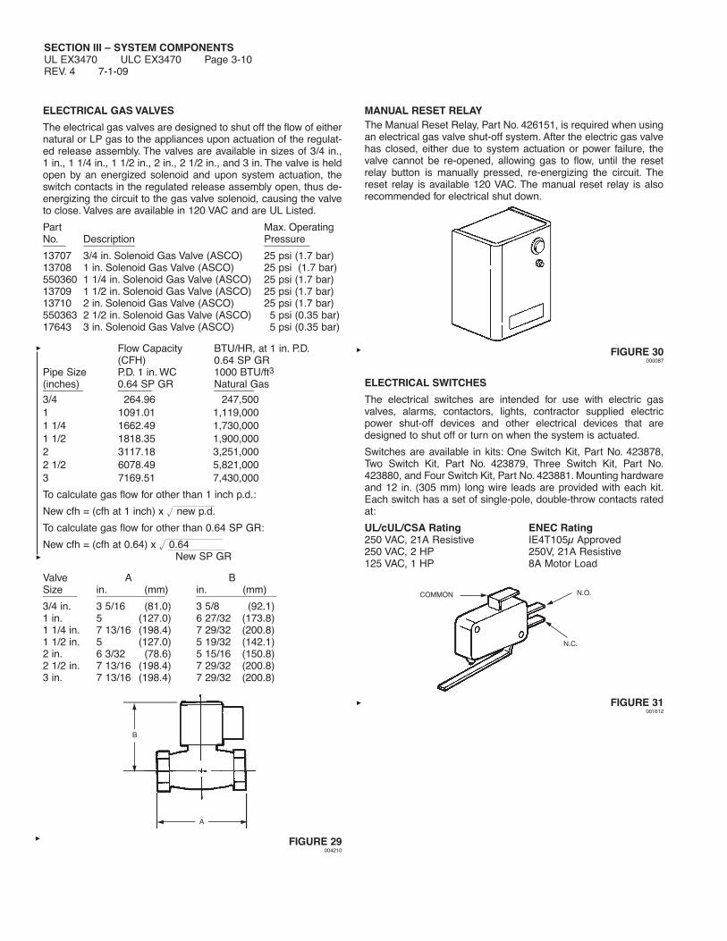
SECTION III – SYSTEM COMPONENTSUL EX3470 ULC EX3470 Page 3-10REV. 4 7-1-09
ELECTRICAL GAS VALVES
The electrical gas valves are designed to shut off the flow of eithernatural or LP gas to the appliances upon actuation of the regulat-ed release assembly. The valves are available in sizes of 3/4 in.,1 in., 1 1/4 in., 1 1/2 in., 2 in., 2 1/2 in., and 3 in. The valve is heldopen by an energized solenoid and upon system actuation, theswitch contacts in the regulated release assembly open, thus de-energizing the circuit to the gas valve solenoid, causing the valveto close. Valves are available in 120 VAC and are UL Listed.
Part Max. OperatingNo. Description Pressure____ _________ ________13707 3/4 in. Solenoid Gas Valve (ASCO) 25 psi (1.7 bar)13708 1 in. Solenoid Gas Valve (ASCO) 25 psi (1.7 bar)550360 1 1/4 in. Solenoid Gas Valve (ASCO) 25 psi (1.7 bar)13709 1 1/2 in. Solenoid Gas Valve (ASCO) 25 psi (1.7 bar)13710 2 in. Solenoid Gas Valve (ASCO) 25 psi (1.7 bar)550363 2 1/2 in. Solenoid Gas Valve (ASCO) 5 psi (0.35 bar)17643 3 in. Solenoid Gas Valve (ASCO) 5 psi (0.35 bar)
Flow Capacity BTU/HR, at 1 in. P.D.(CFH) 0.64 SP GR
Pipe Size P.D. 1 in. WC 1000 BTU/ft3(inches) 0.64 SP GR Natural Gas_______ ______ _______3/4 264.96 247,5001 1091.01 1,119,0001 1/4 1662.49 1,730,0001 1/2 1818.35 1,900,0002 3117.18 3,251,0002 1/2 6078.49 5,821,0003 7169.51 7,430,000
To calculate gas flow for other than 1 inch p.d.:
New cfh = (cfh at 1 inch) x � new p.d.
To calculate gas flow for other than 0.64 SP GR:
New cfh = (cfh at 0.64) x � 0.64 New SP GR
Valve A BSize in. (mm) in. (mm)______ ____________ ______________3/4 in. 3 5/16 (81.0) 3 5/8 (92.1)1 in. 5 (127.0) 6 27/32 (173.8)1 1/4 in. 7 13/16 (198.4) 7 29/32 (200.8)1 1/2 in. 5 (127.0) 5 19/32 (142.1)2 in. 6 3/32 (78.6) 5 15/16 (150.8)2 1/2 in. 7 13/16 (198.4) 7 29/32 (200.8)3 in. 7 13/16 (198.4) 7 29/32 (200.8)
FIGURE 29004210
MANUAL RESET RELAYThe Manual Reset Relay, Part No. 426151, is required when usingan electrical gas valve shut-off system. After the electric gas valvehas closed, either due to system actuation or power failure, thevalve cannot be re-opened, allowing gas to flow, until the resetrelay button is manually pressed, re-energizing the circuit. Thereset relay is available 120 VAC. The manual reset relay is alsorecommended for electrical shut down.
FIGURE 30000087
ELECTRICAL SWITCHES
The electrical switches are intended for use with electric gasvalves, alarms, contactors, lights, contractor supplied electricpower shut-off devices and other electrical devices that aredesigned to shut off or turn on when the system is actuated.
Switches are available in kits: One Switch Kit, Part No. 423878,Two Switch Kit, Part No. 423879, Three Switch Kit, Part No.423880, and Four Switch Kit, Part No. 423881. Mounting hardwareand 12 in. (305 mm) long wire leads are provided with each kit.Each switch has a set of single-pole, double-throw contacts ratedat:
UL/cUL/CSA Rating ENEC Rating250 VAC, 21A Resistive IE4T105μ Approved250 VAC, 2 HP 250V, 21A Resistive125 VAC, 1 HP 8A Motor Load
FIGURE 31001612
A
B
COMMON N.O.
N.C.
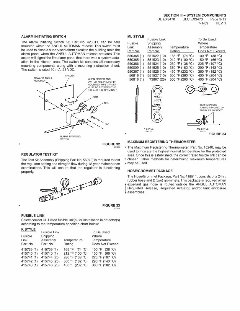
SECTION III – SYSTEM COMPONENTSUL EX3470 ULC EX3470 Page 3-11
7-1-09 REV. 1
ALARM INITIATING SWITCH
The Alarm Initiating Switch Kit, Part No. 428311, can be fieldmounted within the ANSUL AUTOMAN release. This switch mustbe used to close a supervised alarm circuit to the building main firealarm panel when the ANSUL AUTOMAN release actuates. Thisaction will signal the fire alarm panel that there was a system actu-ation in the kitchen area. The switch kit contains all necessarymounting components along with a mounting instruction sheet.The switch is rated 50 mA, 28 VDC.
FIGURE 32004890
REGULATOR TEST KIT
The Test Kit Assembly (Shipping Part No. 56972) is required to testthe regulator setting and nitrogen flow during 12-year maintenanceexaminations. This will ensure that the regulator is functioningproperly.
FIGURE 33000169
FUSIBLE LINKSelect correct UL Listed fusible link(s) for installation in detector(s)according to the temperature condition chart below:
K STYLE________ Fusible Link To Be UsedFusible Shipping WhereLink Assembly Temperature TemperaturePart No. Part No. Rating Does Not Exceed_______ _______ ______ ______________ 415739 (1) 415739 (1) 165 °F (74 °C) 100 °F (38 °C)415740 (1) 415740 (1) 212 °F (100 °C) 150 °F (66 °C)415741 (1) 415744 (25) 280 °F (138 °C) 225 °F (107 °C)415742 (1) 415745 (25) 360 °F (182 °C) 290 °F (143 °C)415743 (1) 415746 (25) 450 °F (232 °C) 360 °F (182 °C)
ML STYLE_________ Fusible Link To Be UsedFusible Shipping WhereLink Assembly Temperature TemperaturePart No. Part No. Rating Does Not Exceed 550368 (1) 551522 (10) 165 °F (74 °C) 100 °F (38 °C)550365 (1) 551523 (10) 212 °F (100 °C) 150 °F (66 °C)550366 (1) 551524 (10) 280 °F (138 °C) 225 °F (107 °C)550009 (1) 551525 (10) 360 °F (182 °C) 290 °F (143 °C)550367 (1) 551526 (10) 450 °F (232 °C) 360 °F (182 °C)56816 (1) 551527 (10) 500 °F (260 °C) 400 °F (204 °C)56816 (1) 73867 (25) 500 °F (260 °C) 400 °F (204 °C)
K STYLE ML STYLE000170 000171
FIGURE 34
MAXIMUM REGISTERING THERMOMETER
The Maximum Registering Thermometer, Part No. 15240, may beused to indicate the highest normal temperature for the protectedarea. Once this is established, the correct rated fusible link can bechosen. Other methods for determining maximum temperaturesmay be used.
HOSE/GROMMET PACKAGE
The Hose/Grommet Package, Part No. 418511, consists of a 24 in.rubber hose and 2 (two) grommets.This package is required whenexpellant gas hose is routed outside the ANSUL AUTOMANRegulated Release, Regulated Actuator, and/or tank enclosureassemblies.
ALARM INITIATINGSWITCH
WHEN SPACER ANDSWITCH ARE PROPERLYMOUNTED, THIS DIVIDERMUST BE BETWEEN THEN.O. AND N.C. TERMINALS
TOWARD ANSULAUTOMAN
N.O.
COM
SPACER
N.C.
TEMPERATURERATING STAMPED ONFUSIBLE LINK BODY

SECTION III – SYSTEM COMPONENTSUL EX3470 ULC EX3470 Page 3-12REV. 1 7-1-09
IN-LINE BURST DISC ASSEMBLY (MANIFOLDED SYSTEMSONLY)
The in-line burst disc assembly is required to eliminate the siphon-ing of the agent up the pipe during extreme temperature variations.In addition to eliminating the siphoning effect, the common in-lineburst disc assembly eliminates the possibility of one or more indi-vidual discs located in the tank adaptor from failing to burst. Theassembly consists of a stainless steel body which houses theburst disc. When utilizing this assembly in a manifolded system, itis necessary to modify (remove) the burst disc located in all of theR-102 tank adaptors in the system. The in-line burst disc assem-bly is to be mounted as close to the tank outlet as possible. Aftersystem discharge, the assembly must be disassembled and a newburst disc installed.
Part No. Description______ _________416970 In-Line Burst Disc Assembly417911 Burst Disc (Pack of 10)
FIGURE 35008383
1/4 IN. CHECK VALVE
The 1/4 in. check valve, Part No. 25627, blocks the flow of actua-tion gas from the actuator that was actuated to the actuator(s) thatwas not actuated. This prevents actuation gas from escaping froman open actuator which may have had the cartridge removed.
FIGURE 36000899
NOZZLE AIMING DEVICEThe Nozzle Aiming Device, Part No. 431992, is available to prop-erly aim each nozzle to the correct aiming point. The deviceclamps to the nozzle and emits a small laser light that reflects onthe surface that it is aiming at. The nozzle can then be rotated topoint at a predetermined aiming point and then tightened to holdthat angle. The aiming device adaptor attaches to the nozzle. Theshipping assembly consists of the aiming device and the adaptor.
FIGURE 37006520
STAINLESS STEEL BRAIDED ACTUATION HOSEThe Stainless Steel Actuation Hose is used to connect the actua-tion line compression tees between each pneumatic actuator. Thehose has the same thread, 7/16-20, as the fittings. The actuationhose allows flexibility between the AUTOMAN and each regulatedactuator.
Hose Part No. Length Couplings____________ ______ _________31809 16 in. (41 cm) 7/16-20 x 7/16-20 Females32335 20 in. (51 cm) 7/16-20 x 7/16-20 Females32336 24 in. (61 cm) 7/16-20 x 7/16-20 Females430815 42 in. (107 cm) 7/16-20 Female x 1/4 in. NPT
FittingPart No. Description_______ __________31810 Male Elbow (7/16-20 x 1/4 in. NPT)31811 Male Tee (7/16-20 x 7/16-20 x 1/4 in. NPT)415371 Tee (7/16-20 x 1/8 in. Male NPT x 1/8 in. Female NPT)32338 Male Straight Connector (7/16-20 x 1/4 in. NPT)25627 1/4 in. Check Valve
FIGURE 38000433
AGENT DISTRIBUTION HOSE AND RESTRAINING CABLE KIT
The Agent Distribution Hose and Restraining Cable Kit, Part No.435982, consists of a 5 ft (1.5 m) long Agent Distribution Hose, a3 ft (0.9 m) long Restraining Cable, and a Restraining CableHardware Package. The Agent Distribution Hose can be utilizedwith castered cooking appliances with castered supports found incommercial kitchens. The hose allows for movement of the appli-ance for cleaning without having to disconnect any fire suppres-sion system discharge piping.
Note: The Agent Distribution Hose is authorized for use with onlyUL Listed ANSUL Wet Chemical Restaurant Fire SuppressionSystems.
7/16-207/16-20
ADAPTOR
NOZZLEAIMINGDEVICE
1/4 IN. NPT(0.6 cm)
CHECK VALVE PART NO. 25627
2 IN.(5.1 cm)
1.54 IN.(3.9 cm)
RED SIDE OF BURSTDISC TO BE TOWARDSADAPTOR, PART NO.417707

SECTION IV – SYSTEM DESIGNUL EX3470 ULC EX3470 Page 4-1
7-1-09 REV. 8
SYSTEM DESIGN
The ANSUL R-102 Restaurant Fire Suppression System may beused on a number of different types of restaurant cooking appli-ances and hood and duct configurations. The design informationlisted in this section deals with the limitations and parameters ofthis pre-engineered system. Those individuals responsible for thedesign of the R-102 system must be trained and hold a currentANSUL certificate in an R-102 training program.The R-102 and the PIRANHA systems use compatible agents andcomponents, therefore, they may be used together for cookingappliance, hood, and duct protection. The primary ANSULAUTOMAN Release can be either an R-102 or a PIRANHAANSUL AUTOMAN Release and can actuate up to two additionalR-102 or PIRANHA Regulated Actuators. In systems utilizing a101 remote release, any combination of the maximum number ofregulated actuators can be used.• Both systems must actuate simultaneously.• Each system must be designed and installed per its appropri-
ate manual.• Adjacent appliances requiring protection must be protected
with the same type of system, either R-102 or PIRANHA,unless the center-to-center spacing between the adjacentR-102 and PIRANHA nozzles is no less than 36 in. (91.4 cm).
• When appliances are protected with R-102 nozzles, the hoodand connecting duct above those appliances cannot be pro-tected with PIRANHA nozzles.
• Mixing systems in a common plenum is not allowed.
One of the key elements for restaurant fire protection is a correctsystem design. This section is divided into ten sub-sections: Noz-zle Placement Requirements, Tank Quantity Requirements, Actu-ation and Expellant Gas Line Requirements, Distribution PipingRequirements, Detection System Requirements, Manual Pull Sta-tion Requirements, Mechanical Gas Valve Requirements, Electri-cal Gas Valve Requirements, Electrical Switch Requirements, andPressure Switch Requirements. Each of these sections must becompleted before attempting any installation. System designsketches should be made of all aspects of design for referenceduring installation.
NOZZLE PLACEMENT REQUIREMENTS
This section gives guidelines for nozzle type, positioning, andquantity for duct, plenum, and individual appliance protection. Thissection must be completed before determining tank quantity andpiping requirements.
Duct Protection – Single Nozzle
All duct protection is UL listed without limitation of maximum ductlength (unlimited length). This includes all varieties of ductworksboth horizontal and vertical including ducts that run at angles tothe horizontal and ducts with directional bends.
The R-102 system uses different duct nozzles depending on thesize of duct being protected.
GENERAL INFORMATION
1. Nozzles must be located 2-8 in. (5-20 cm) into the center of theduct opening, discharging up. See Figure 1.
FIGURE 1000173
2. In installations where a UL listed damper assembly isemployed, the duct nozzle can be installed beyond the 8 in.(20 cm) maximum, to a point just beyond the damper assem-bly that will not interfere with the damper. Exceeding the maxi-mum of 8 in. (20 cm) in this way will not void the UL listing ofthe system.
3. Previously listed 3 flow number and 5 flow number duct pro-tection detailed in earlier published manual, Part No. 418087-06, can also still by utilized.
• One 1W nozzle (Part No. 419336) = one flow number
• 50 in. (127 cm) perimeter maximum
• 16 in. (41 cm) diameter maximum
• One 2W Nozzle (Part No. 419337) = two flow numbers
• 100 in. (254 cm) perimeter maximum
• 32 in. (81.3 cm) diameter maximum
The chart below shows the maximum protection available fromeach duct nozzle.
Part 3.0 Gallon 1.5 GallonDescription No. System System_________ ____ ________ _________
2W Nozzle 419337 Maximum Maximum100 in. (254 cm) 100 in. (254 cm)Perimeter Perimeter
1W Nozzle 419336 Maximum Maximum50 in. (127 cm) 50 in. (127 cm)Perimeter Perimeter
DUCT SIZES UP TO 100 IN. (254 cm)PERIMETER/ 32 IN. (81.3 cm) DIAMETER
DUCT SIZES UP TO 50 IN. (127 cm)PERIMETER/ 16 IN. (41 cm) DIAMETER
2 – 8 IN.(5 – 20 cm)

SECTION IV – SYSTEM DESIGNUL EX3470 ULC EX3470 Page 4-2REV. 4 4-1-06
Duct Protection – Multiple Nozzle
• One 1W Nozzle (Part No. 419336) and one 2W Nozzle(Part No. 419337) = three flow numbers
• 135 in. (343 cm) perimeter maximum
• No round duct option available
• Follow design table in Figure 2 to determine maximum modulesize for each nozzle
1W Module 2W ModuleSide A Side B Side B Side BMaximum Maximum Maximum Maximumin. (cm) in. (cm) in. (cm) in. (cm)__ ____ __ ____ __ ____ __ ____4 (10) 60.0 (152) 23.0 (58) 37.0 (94)5 (13) 60.0 (152) 23.0 (58) 37.0 (94)6 (15) 59.5 (151) 22.5 (57) 37.0 (94)7 (18) 59.0 (150) 22.0 (56) 37.0 (94)8 (20) 58.5 (149) 22.0 (56) 36.5 (93)9 (23) 58.0 (147) 21.5 (55) 36.5 (93)
10 (25) 57.0 (145) 21.0 (53) 36.0 (91)11 (28) 56.0 (142) 20.5 (52) 35.5 (90)12 (31) 55.5 (141) 20.0 (51) 35.5 (90)13 (33) 54.5 (138) 19.5 (50) 35.0 (89)14 (36) 53.5 (136) 18.5 (47) 35.0 (89)15 (38) 52.0 (132) 18.0 (46) 34.0 (86)16 (41) 51.0 (130) 17.0 (43) 34.0 (86)17 (43) 49.5 (126) 16.0 (41) 33.5 (85)18 (46) 47.5 (121) 14.5 (37) 33.0 (84)19 (48) 46.0 (117) 13.5 (34) 32.5 (83)20 (51) 43.5 (111) 12.0 (31) 31.7 (81)21 (53) 41.0 (104) 10.0 (25) 31.0 (79)22 (56) 38.0 (97) 7.5 (19) 30.5 (78)23 (58) 33.5 (85) 4.0 (10) 29.5 (75)
FIGURE 2006521
Example: Protection is required for a duct that has an "A" dimen-sion of 8.0 in. (20 cm) wide and a "B" dimension of 55 in. (140 cm)long.
Referring to the table in Figure 2, if the "A" dimension is 8.0 in. (20cm), the "B" dimension must not exceed 58.5 in. (149 cm). In thisexample, the "B" dimension is 55 in. (140 cm), therefore, this ductcan be protected with a three flow application.
Read over from the 8.0 in. (20 cm) line on the table to the 1WModule column. At that point, the chart shows that the "B" modulelength for the 1W nozzle can be 22.0 in. (56 cm). Center the 1Wnozzle in that module. The 2W module can now be centered with-in the remaining module.
DUCT SIZES UP TO 135 IN. (343 cm) PERIMETER – 3FLOW OPTION

SECTION IV – SYSTEM DESIGNUL EX3470 ULC EX3470 Page 4-3
7-1-09 REV. 5
Duct Protection – Multiple Nozzle (Continued)
• Ducts over 100 in. (254 cm) perimeter may be modularized using2W nozzles (Part No. 419337)
• No round duct option available
• Follow the design chart to determine maximum module size foreach 2W nozzle
• When determining number of nozzles required, it is sometimesan advantage to check the chart using the shortest side as Side"A" and then recheck it using the longest side as Side "A". Thiscomparison may reveal a need for a lesser quantity of nozzlesone way versus the other way.
When working with Chart 1, the quantity of nozzles determinedmust be equally divided within the duct area.
When working with Chart 2, one half of the quantity of nozzlesdetermined must be equally positioned in the top half of the areaof the duct and the remaining half of the nozzles must be posi-tioned in the bottom half of the duct area.
Example: The duct to be protected has a Side "A" of 40 in.(101.6 cm) and a Side "B" of 60 in. (152.4 cm). Referring to thedesign chart, this duct requires 4 nozzles. One half of 4 = 2.Therefore, 2 nozzles must be equally positioned in each of the twoduct areas. See Figure 3.
FIGURE 3006523
DUCT SIZES GREATER THAN 100 IN. (254 cm) PERIMETER
25
456789
101112131415161718192021222324252627282930313233343536
101315182023252830333638414346485153565861646669717476798184868991
91949799102104107109112114117119122
36373839404142434445464748
6765
26 28 30 32 34 36 38 40 42 44 46 48 50 52 54 56 58 60 62 64 66 68 70 7227 29 31 33 35 37 39 41 43 45 47 49 51 53 55 57 59 61 63 65 67 69 71
1
2
3
2
4
4
5
6
64 66 69 71 74 76 79 81 84 86 89 91 94 97 99 102 104 107 109 112 114 117 119 122 124 127 130 132 135 137 140 142 145 147 150 152 155 157 160 163 165 168 170 173 175 178 180 183in.cm
60 IN.(152 cm)
40 IN.(102 cm)
30 IN. (76 cm)
CHART NO. 1
30 IN. (76 cm)
20 IN.(51 cm)
20 IN.(51 cm)
SIDE “B”
SIDE “B”
SIDE“A”
SIDE“A”in.
in.cm
SIDE“A”cm
CHART NO. 2
A
ANOTE: NOZZLE QUANTITIES LISTED IN CHART 2 MUST BE EQUALLY DIVIDED INTO EACH OF THE TWO DUCT MODULES.
006522
B
B

SECTION IV – SYSTEM DESIGNUL EX3470 ULC EX3470 Page 4-4REV. 7 7-1-09
Transition Protection
Transitions are protected at a point in the transition where theperimeter or the diameter is equal to or less than the maximumsize duct that can be protected. The nozzle(s) must be located inthe center of the area at that point, or center of the module pro-tected when more than one duct nozzle is required. Note: Nozzlesto protect ducts with a transition that is more than 4 ft (1.2 m)in height, will be required to be positioned in the opening ofthe transition from the hood 2 to 8 in. (5.1 to 20.3 cm) into theopening using standard duct nozzle design parameters. SeeFigure 4.
FIGURE 4000174
Electrostatic Precipitator Protection
Some restaurant ventilating ducts have an electrostatic precipita-tor installed at or near the base. These precipitators are generallysmall and are used to aid in the cleaning of exhaust air.
Ducts with precipitators located at or near the base can be pro-tected using duct nozzle(s) above the precipitator and 1/2N noz-zle(s) (Part No. 419334) for the precipitator. One 1/2N nozzle mustbe used for each cell being protected. This nozzle tip is stampedwith 1/2N, indicating that it is a 1/2-flow nozzle and must be count-ed as 1/2 flow number.
When protecting ducts equipped with precipitators, the duct noz-zle(s) must be installed above the precipitator and aimed to dis-charge downstream. If the area above the precipitator is a duct, thenozzle(s) must be positioned according to duct protection guide-lines. If the area above the precipitator is a transition, the transitionguidelines must be followed.
The 1/2N nozzle (Part No. 419334) must be centered 10 to 26 in.(25 to 66 cm) below the precipitator and aimed to discharge at thecenter of each precipitator cell. However, if it is physically impossi-ble to mount the nozzle at 10 to 26 in. (25 to 66 cm) due to pre-cipitator placement, the nozzle may be mounted closer than 10 in.(25 cm). See Figure 5.
* IF PHYSICALLY IMPOSSIBLE AT 10 TO 26 IN. (25 TO 66 cm), NOZZLE MAY BEMOUNTED CLOSER THAN 10 IN. (25 cm).
FIGURE 5000196
Note: For protection of Pollution Control Units (PCUs) or air scrub-bers with or without ESPs, contact Ansul Technical Services fornon-UL listed recommended application.
DUCT
TRANSITION
DUCTNOZZLE
SEE DUCT FORTRANSITIONPROTECTION
PRECIPITATOR
10-26 IN.*(25-66 cm)
NOZZLE FORPRECIPITATORPROTECTION
4 FT(1.2 m)MAX.

Plenum Protection
The R-102 system uses the 1W Nozzle (Part No. 419336) or the1N Nozzle (Part No. 419335) for plenum protection. The 1W noz-zle tip is stamped with 1W and the 1N nozzle tip is stamped with1N, indicating they are one-flow nozzles and must be counted asone flow number each. When protecting a plenum chamber, theentire chamber must be protected regardless of filter length.
VERTICAL PROTECTION – GENERAL1W NOZZLE – PART NO. 419336 – SINGLE AND “V” BANKPROTECTION
One 1W nozzle will protect 4 linear feet (1.2 m) of plenum. Themaximum distance from the end of the hood to the first and lastnozzle must be no more than 2 ft (0.6 m). After the first nozzle, anyadditional nozzles must be positioned at a maximum of 4 ft (1.2 m)apart down the entire length of the plenum.The plenum width mustnot exceed 4 ft (1.2 m). (The 1W nozzle can be used on single orV-bank filter arrangements.) See Figure 6.
FIGURE 6000197
When protecting plenums with the 1W nozzle, two options of cov-erage are available:
Option 1: The 1W nozzle must be on the center line of the singleor “V” bank filter and positioned within 1-20 in.(2.5-51 cm) above the top edge of the filter. SeeFigure 7.
FIGURE 7000199
Option 2: The 1W nozzle must be placed perpendicular, 8-12 in.(20-30 cm) from the face of the filter and angled to thecenter of the filter. The nozzle tip must be within 2 in.(5 cm) from the perpendicular center line of the filter.See Figure 8.
FIGURE 8000200
HORIZONTAL PROTECTION – OPTION 1
1N NOZZLE – PART NO. 419335 – SINGLE BANK PROTECTION
One 1N nozzle will protect 10 linear feet (3.1 m) of single filter bankplenum. The nozzle(s) must be mounted in the plenum, 2 to 4 in.(5 to 10 cm) from the face of the filter, centered between the filterheight dimension, and aimed down the length. The nozzle must bepositioned 0-6 in. (0-15 cm) from the end of the hood to the tip of thenozzle. See Figure 9.
FIGURE 9
SECTION IV – SYSTEM DESIGNUL EX3470 ULC EX3470 Page 4-5
7-1-09 REV. 5
2 FT (0.6 m)MAXIMUM
4 FT (1.2 m)MAXIMUM
4 FT (1.2 m)MAXIMUM
2 FT (0.6 m)MAXIMUM
4 FT (1.2 m)MAXIMUM
20 IN. (51 cm)MAXIMUM
1 IN. (2.5 cm)MINIMUM
20 IN. (51 cm)MAXIMUM
1 IN. (2.5 cm)MINIMUM
000201
NOZZLE TIPMUST BE WITHINTHIS AREA
4 IN.(10 cm)
12 IN. (30 cm)MAXIMUM
8 IN. (20 cm)MINIMUM
2 – 4 IN.(5 – 10 cm)
10 FT. (3.1 m)MAXIMUM
000202

Plenum Protection (Continued)
HORIZONTAL PROTECTION – OPTION 2
1W NOZZLE – PART NO. 419336 – “V” BANK PROTECTION
One 1W nozzle will protect 6 linear feet (1.8 m) of “V” bank plenum.The nozzle must be mounted horizontally, positioned 1/3 the filterheight down from the top of the filter. Nozzles can be located at 6 ft(1.8 m) spacings on longer plenums. The nozzle must be positioned0-6 in. (0-15 cm) from the end of the hood to the tip of the nozzle.See Figure 10.
FIGURE 10006524
TWO (2) 1N NOZZLES – PART NO. 419335 – “V” BANK PRO-TECTION
Two 1N nozzles will protect 10 linear feet (3.1 m) by 4 ft (1.2 m)wide of “V” bank plenum. The nozzles must be mounted in theplenum, 2 to 4 in. (5 to 10 cm) from the face of the filter, centeredbetween the filter height dimension, and aimed down the length.The nozzle must be positioned 0-6 in. (0-15 cm) from the end of thehood to the tip of the nozzle. See Figure 11.
FIGURE 11
For a plenum, either single or “V” bank, with a linear extensionlonger than 10 ft (3.1 m), each bank may be protected using one1N nozzle every 10 ft (3.1 m) or less depending on the overalllength of the plenum. See Figure 12. The nozzles may point in theopposite directions as long as the entire plenum area is protected,and the 10 ft (3.1 m) limitation is not exceeded. See Figure 13.Thenozzle positioning shown in Figure 14 is not an acceptable methodof protection because the plenum area directly under the tee is notwithin the discharge pattern of either nozzle.
FIGURE 12000206
FIGURE 13000207
FIGURE 14000208
SECTION IV – SYSTEM DESIGNUL EX3470 ULC EX3470 Page 4-6REV. 7 7-1-09
2 – 4 IN.(5 – 10 cm)
2 – 4 IN.(5 – 10 cm)
10 FT (3.1 m)MAXIMUM
000203
000204
4 FT (1.2 m)MAXIMUM
6 FT (1.8 m)MAXIMUM
HEIGHT OFFILTER (H)
1/3 (H)
1W NOZZLE
10 FT (3.1 m)MAXIMUM
10 FT (3.1 m)MAXIMUM
10 FT (3.1 m)MAXIMUM
30 FT (9.1 m)
INCORRECT
10 FT (3.1 m)MAXIMUM
10 FT (3.1 m)MAXIMUM
10 FT (3.1 m)MAXIMUM
30 FT (9.1 m)
4 FT(1.2 m)
MAXIMUM

SECTION IV – SYSTEM DESIGNUL EX3470 ULC EX3470 Page 4-7
10-1-02 REV. 3
Appliance Protection
The following pages detail types of appliance protection. Eachdesign requires several factors: correct nozzle choice, correct noz-zle height above hazard, correct nozzle location and correct aim-ing point.
Fryer – Single Nozzle Protection
1. Design requirements for fryers are broken down into twotypes.
A. FRYERS WITHOUT DRIPBOARDS
If the fryer does not include a dripboard, measure theinternal depth (horizontal dimension from front to back)and length of the frypot.
B. FRYERS WITH DRIPBOARDS
If the fryer includes any dripboard areas, measure boththe internal depth (horizontal dimension from front toback) and length of the frypot portion, and then measurethe internal depth and length of the overall hazard areaincluding any dripboard areas.
2. Using Table, “Maximum Cooking Area Dimension – SingleNozzle Fryer Protection,” determine which nozzle is neededto protect the fryer based on the maximum dimensions listed.
A. If the fryer does not include a dripboard, use the maxi-mum dimensions listed in the first column of the table toselect the correct nozzle.
B. If the fryer includes any dripboard areas, use both themaximum frypot dimensions in the first column of thetable, and the maximum overall dimensions in the secondcolumn of the table to select the correct nozzle. None ofthe maximum dimensions in either column may beexceeded.
3. If either the maximum frypot or the overall sizes are exceed-ed, an additional nozzle(s) will be required. Refer to the mul-tiple nozzle requirements.
Example: A fryer with a dripboard. The inside of the frypot withoutthe dripboard measures 18 in. in depth x 18 in. in length (46 cm x46 cm) and the inside of the overall area including the dripboardmeasures 18 in. in depth x 24 in. in length (46 cm x 61 cm). Fromthe Table “Maximum Cooking Area Dimension – Single NozzleFryer Protection,” either the 3N or the 290 nozzle should be select-ed to protect the fryer, depending on the maximum nozzle heightabove the fryer and the positioning requirements allowed. Refer toappropriate Figures.

SECTION IV – SYSTEM DESIGNUL EX3470 ULC EX3470 Page 4-8REV. 6 4-1-06
Fryer – Single Nozzle Protection (Continued)
Maximum Area Dimensions – Single Nozzle Fryer Protection
Max. SizeMax. Size Overall Type of Nozzle Height NozzleFrypot Only With Dripboard Nozzle Above Top of Fryer Location__________ ____________ ______ ________________ _______
Full or Split Vat Full or Split Vat 230 27 in. to 47 in. See Figure14 in. x 15 in. 14 in. x 21 in. (69 cm to 119 cm) 15 and 16(36 cm x 38 cm) (36 cm x 53 cm)
Full or Split Vat Full or Split Vat 245 20 in. to 27 in. See Figure14 in. x 15 in. 14 in. x 21 in. (51 cm to 69 cm) 15 and 16(36 cm x 38 cm) (36 cm x 53 cm)
Full or Split Vat Full or Split Vat 290 13 in. to 16 in. See Figure 1714 in. x 15 in. 14 in. x 21 in. (33 cm to 41 cm)(36 cm x 38 cm) (36 cm x 53 cm)
Full or Split Vat Full or Split Vat 290 16 in. to 27 in. See Figure 1714 1/2 in. x 14 in. 14 1/2 in. x 26 1/2 in. (41 cm to 69 cm)(37 cm x 38 cm) (37 cm x 67 cm)
FIGURE 15002280
FIGURE 16002283
TOP OF FRYER
FRYER WITHOUT DRIPBOARD FRYER WITH DRIPBOARD FRYER WITHOUT DRIPBOARD FRYER WITH DRIPBOARD
TOP OF FRYER
SPLIT VAT
NOZZLE TIP POSITIONED ANYWHERE ALONG OR WITHIN PERIMETER OF COOKINGSURFACE AND AIMED TO THE CENTER OF THE COOKING AREA.
NOZZLE TIP POSITIONED ANYWHERE ALONG OR WITHIN PERIMETER OF COOKINGSURFACE AND AIMED TO THE CENTER OF THE COOKING AREA.

SECTION IV – SYSTEM DESIGNUL EX3470 ULC EX3470 Page 4-9
4-1-06 REV. 8
Fryer – Single Nozzle Protection (Continued)
Maximum Area Dimensions – Single Nozzle Fryer Protection (Continued)
Max. SizeMax. Size Overall Type of Nozzle Height NozzleFrypot Only With Dripboard Nozzle Above Top of Fryer Location__________ ____________ ______ ________________ _______
19.5 in. x 19 in. 19.5 in. x 25 3/8 in. 290 13 in. to 16 in. See Figure 17(50 cm x 48 cm) (50 cm x 65 cm) (33 to 41 cm)
19.5 in. x 19 in. 19.5 in. x 25 3/8 in. 3N See Figure See Figure 18(50 cm x 48 cm) (50 cm x 65 cm) 18
18 in. x 18 in. 18 in. x 27 3/4 in. 3N 25 in. to 35 in. See Figure 19(46 cm x 46 cm) (46 cm x 70.5 cm) (64 cm to 89 cm)
FRYER WITHOUT DRIPBOARD FRYER WITH DRIPBOARD
290 NOZZLE TIP POSITIONED OVER THE MIDPOINT OF THE HAZARD AREA ± 3 IN.(7.6 cm) FROM THE MIDPOINT ALONG THE LONGEST SIDE OF THE HAZARD AND ± 1IN. (2.5 cm) FROM THE MIDPOINT ALONG THE SHORTEST SIDE OF THE HAZARD ANDAIMED AT THE MIDPOINT OF THE COOKING AREA.
FIGURE 17002286
FRYER WITHOUT DRIPBOARD FRYER WITH DRIPBOARD
3N NOZZLE TIP POSITIONED ANYWHERE ALONG OR WITHIN PERIMETER OFCOOKING SURFACE AND AIMED TO THE CENTER OF THE COOKING AREA.
FIGURE 18002287
FRYER WITHOUT DRIPBOARD FRYER WITH DRIPBOARD
FIGURE 19
000008
NOTE: 3N NOZZLE TIP MUST BE LOCATED WITHIN THE PERIMETER OF THE SURFACEAREA WITHIN THE FRONT HALF OF THE FRY POT AND AIMED AT THE CENTER.
TOP OF FRYER
RIGHT-TO-LEFTCENTERLINE
000010
FRONTFRONT
34 IN. (86 cm) MAXIMUM DIAGONALDISTANCE BETWEEN NOZZLE ANDCENTER OF HAZARD AREA
21 in. (53 cm)MINIMUMVERTICALNOZZLEHEIGHT

Fryer – Multiple Nozzle Protection
Design Requirements:Fryers exceeding the coverage of a single nozzle can be dividedinto modules. Each module must not exceed the maximum areaallowed for a single nozzle. However, when utilizing multiple nozzleprotection, the longest side allowed for a fryer with dripboard canbe used, regardless of whether the fryer has a dripboard or not.
The maximum size fryer that can be modularized is 864 in.2(5574 cm2) or in terms of ft, 6 ft2 (0.6 m2).1. Design requirements for multiple nozzle fryers are broken
down into two types:
A. FRYERS WITHOUT DRIPBOARD(S)If the fryer does not include a dripboard, measure the inter-nal depth (horizontal dimension from front to back) andlength of the frypot. Then, multiply the depth and length toobtain the area of the frypot in square inches.
B. FRYERS WITH DRIPBOARD(S)If the fryer includes any dripboard areas, measure both theinternal depth and length of the frypot portion, and thenmeasure the internal depth and length of the overall hazardarea including any dripboard areas.Determine the area of both the frypot and the area of theoverall vat by multiplying corresponding depth and lengthdimensions.
2. Divide the frypot or overall vat into modules, each of which canbe protected by a single nozzle, based on the maximumdimension and area coverage of the nozzle as specified inTable, “Maximum Cooking Area Dimension – Multiple NozzleProtection.”A. If the module considered does not include any portion of
the dripboard, use only the maximum frypot area and max-imum dimension listed in the first column of the table toselect the correct nozzle.
B. If the module considered includes any dripboard areas, useboth the maximum frypot area and dimension listed in thefirst column of the table, and the maximum overall area anddimensions listed in the second column of the table toselect the correct nozzle.
3. None of the maximum dimensions in either column may beexceeded. If either the maximum frypot or the overall sizes areexceeded, the area divided into modules will need to be rede-fined with the possibility of an additional nozzle.
Options For Modularizing FryersThe following Figure 20 shows approved methods of dividing (mod-ularizing) fryers so that each section can be properly protected.
Example: A fryer with a dripboard. The inside vat without the drip-board measures 18 in. in depth x 30 in. in length (46 cm. x 76 cm)and the inside of the overall vat including the dripboard measures24 in. in depth x 30 in. in length (61 cm x 76 cm). Because the fryeris 30 in. (76 cm) in length, it exceeds the coverage of a singlenozzle.
Dividing the length in half, each module now has an overall vatdimension of 24 in. in depth x 15 in. in length (61 x 38 cm). Fromthe Table, “Maximum Cooking Area Dimension – Multiple NozzleFryer Protection,” either the 3N or the 290 nozzle should be select-ed to protect each fryer module, depending on the maximum noz-zle height above the fryer and the positioning requirementsallowed. Refer to appropriate Figures, 15 through 19.
See additional examples in Appendix Section.
FIGURE 20
SECTION IV – SYSTEM DESIGNUL EX3470 ULC EX3470 Page 4-10REV. 7 7-1-09
EACH MODULAR AREA, INCLUDING DRIPBOARD,MUST NOT EXCEED 497 IN.2 (3207 cm2)
MIDPOINT MIDPOINT
DRIP BOARDDRIP BOARD
EXAMPLE ONLYFRYER WITH DRIPBOARD
000214 EXAMPLE ONLYFRYER WITH DRIPBOARD
DRIP BOARD
AREA OF EACH FRYPOT MODULECANNOT EXCEED324 IN.2
(2090 cm2)
AREA OF THISMODULE (FRYPOT PLUS DRIPBOARD) CANNOTEXCEED497 IN.2
(3206 cm2)
000215
EXAMPLE ONLYFRYER WITHOUT DRIPBOARD
AREA OF EACH FRY POT MODULECANNOT EXCEED 324 IN.2 (2090 cm2)
002296
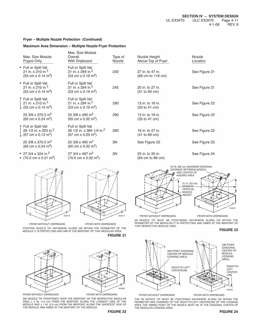
Fryer – Multiple Nozzle Protection (Continued)
Maximum Area Dimension – Multiple Nozzle Fryer Protection
Max. Size ModuleMax. Size Module Overall Type of Nozzle Height NozzleFrypot Only With Dripboard Nozzle Above Top of Fryer Location_______________ _______________ ______ ________________ _______
Full or Split Vat Full or Split Vat21 in. x 210 in.2 21 in. x 294 in.2 230 27 in. to 47 in. See Figure 21(53 cm x 0.14 m2) (53 cm x 0.19 m2) (69 cm to 119 cm)
Full or Split Vat Full or Split Vat21 in. x 210 in.2 21 in. x 294 in.2 245 20 in. to 27 in. See Figure 21(53 cm x 0.14 m2) (53 cm x 0.19 m2) (51 to 69 cm)
Full or Split Vat Full or Split Vat21 in. x 210 in.2 21 in. x 294 in.2 290 13 in. to 16 in. See Figure 22(53 cm x 0.14 m2) (53 cm x 0.19 m2) (33 to 41 cm)
25 3/8 x 370.5 in2 25 3/8 x 495 in2 290 13 in. to 16 in. See Figure 22(65 cm x 0.24 m2) (65 cm x 0.32 m2) (33 to 41 cm)
Full or Split Vat Full or Split Vat26 1/2 in. x 203 in.2 26 1/2 in. x 384 1/4 in.2 290 16 in. to 27 in. See Figure 22(67 cm x 0.13 m2) (67 cm x 0.25 m2) (41 to 69 cm)
25 3/8 x 370.5 in2 25 3/8 x 495 in2 3N See Figure 23 See Figure 23(65 cm x 0.24 m2) (65 cm x 0.32 m2)
27 3/4 x 324 in.2 27 3/4 x 497 in2 3N 25 in. to 35 in. See Figure 24(70.5 cm x 0.21 m2) (70.5 cm x 0.32 m2) (64 cm to 89 cm)
SECTION IV – SYSTEM DESIGNUL EX3470 ULC EX3470 Page 4-11
4-1-06 REV. 8
FRYER WITHOUT DRIPBOARD FRYER WITH DRIPBOARD
3N NOZZLE TIP MUST BE POSITIONED ANYWHERE ALONG OR WITHIN THEPERIMETER OF THE MODULAR IT IS PROTECTING AND AIMED AT THE MIDPOINT OFTHAT RESPECTIVE MODULE AREA.
FIGURE 23
34 IN. (86 cm) MAXIMUM DIAGONALDISTANCE BETWEEN NOZZLE
AND CENTER OFHAZARD AREA
21 in. (53 cm)MINIMUMVERTICALNOZZLEHEIGHT
AIM POINT (DIAGONALCENTER OF MODULECOOKING AREA)
RIGHT-TO-LEFTCENTERLINE
AIM POINT(DIAGONALCENTER OFMODULECOOKINGAREA)
RIGHT-TO-LEFTCENTER-LINE
FRYER WITHOUT DRIPBOARD FRYER WITH DRIPBOARD
THE 3N NOZZLE TIP MUST BE POSITIONED ANYWHERE ALONG OR WITHIN THEPERIMETER AND FORWARD OF THE RIGHT-TO-LEFT CENTERLINE OF THE COOKINGAREA. THE AIMING POINT OF THE NOZZLE MUST BE AT THE DIAGONAL CENTER OFTHE MODULAR COOKING AREA.
FIGURE 24
002293
002291
000213000218
FRYER WITHOUT DRIPBOARD FRYER WITH DRIPBOARD
POSITION NOZZLE TIP ANYWHERE ALONG OR WITHIN THE PERIMETER OF THEMODULE IT IS PROTECTING AND AIM AT THE MIDPOINT OF THAT MODULAR AREA.
FIGURE 21
FRYER WITHOUT DRIPBOARD FRYER WITH DRIPBOARD
290 NOZZLE TIP POSITIONED OVER THE MIDPOINT OF THE RESPECTIVE MODULARAREA ± 3 IN. (7.6 cm) FROM THE MIDPOINT ALONG THE LONGEST SIDE OF THEMODULE AND ± 1 IN. (2.5 cm) FROM THE MIDPOINT ALONG THE SHORTEST SIDE OFTHE MODULE AND AIMED AT THE MIDPOINT OF THE MODULE.
FIGURE 22
002290

SECTION IV – SYSTEM DESIGNUL EX3470 ULC EX3470 Page 4-12REV. 6 7-1-09
Multiple Nozzle Fryer Protection – Tilt Skillet / Braising Pan
Protection for tilt skillets or braising pans is to be based upon thecoverage limitations provided for deep fat fryer protection. Refer toSection IV, DESIGN, starting on Page 4-10, for maximum fryernozzle coverages and maximum fryer nozzle height limitations.
Although the maximum 6 ft2 (0.6 m2) total surface cooking arearequirement applies to fryer protection, it does not apply to tilt skil-lets or braising pans.
Each tilt skillet/braising pan protected module must not exceed thefryer limitations for “MAXIMUM SIZE MODULE OVERALL WITHDRIPBOARD” coverage per nozzle as described in Table on Page4-11.
Tilt skillets and braising pans generally utilize a hinged cover. Fryerprotection nozzles are to be placed toward the front of the appli-ance to minimize the potential for the tilt skillet or braising pancover to interfere with the nozzle discharge. See Figures 25 and26.
FIGURE 25
FIGURE 26
THE NOZZLE IS TO BE PLACED TOWARD THE FRONT OF THE APPLIANCE TO MINIMIZETHE POTENTIAL FOR THE SKILLET OR BRAISING PAN COVER TO INTERFERE WITH THENOZZLE DISCHARGE.
FRYER NOZZLE USED FOR TILT SKILLET OR BRAISING PAN PROTECTION MUST BEPOSITIONED NEAR THE FRONT EDGE OF THE PAN AND AIMED AT THE FRONT TO BACKCENTERLINE OF THE PAN. THE DISCHARGE FROM THE NOZZLE(S) MUST COMPLETELYCLEAR THE PAN COVER WITH AN UNOBSTRUCTED VIEW TO THE BACK OF THE PAN.
000011
COVER MUST NOT INTERFERE WITHNOZZLE DISCHARGE
COVER MUST NOTINTERFERE WITH EDGEOF DISCHARGE PATTERN
FOR MINIMUMAND MAXIMUMNOZZLEHEIGHTS, REFERTO FRYERNOZZLEPARAMETERS
000071

Range Protection
The R-102 system uses five different nozzles for the protection ofranges. Two of the design options require a one-flow nozzle andthree of the design options require two-flow nozzles.
NOTICEA 13 in. (33 cm) diameter wok pan is the largestwok size that can be protected on ranges.
When protecting hot top ranges, the entirecooking surface must be protected.
Range Protection 1N (1-Flow) Nozzle – High ProximityApplication
No Obstructions
Single and multiple burner ranges can be protected using a 1Nnozzle, Part No. 419335. The nozzle tip is stamped with 1N, indi-cating that this is a one-flow nozzle and must be counted as oneflow number.
When using this nozzle for range protection, the maximum lengthof the burner grates being protected with a single nozzle must notexceed 32 in. (81 cm) and the maximum area of the burner gratesmust not exceed 384 in.2 (2477 cm2) per nozzle.
When protecting a range, the 1N nozzle must be located a maxi-mum of 10 in. (25.4 cm) from each burner grate centerline andmust be aimed at the center of the cooking surface. See Figures27 and 28.
FIGURE 27
FIGURE 28
SECTION IV – SYSTEM DESIGNUL EX3470 ULC EX3470 Page 4-13
7-1-09 REV. 8
40 IN.(102 cm)
30 IN.(76 cm)
006539
32 IN.(81 cm)
MAXIMUM
AIMINGPOINT
10 IN.(25 cm)MAXIMUM
10 IN.(25 cm)MAXIMUM
1NNOZZLE
006540

SECTION IV – SYSTEM DESIGNUL EX3470 ULC EX3470 Page 4-14REV. 6 7-1-09
Range Protection 245 (2-Flow) Nozzle – High ProximityApplication
No Obstructions
40 in. to 50 in. (102 cm to 127 cm) above the cooking surface.
This high proximity application uses the 245 nozzle, Part No.419340.
The nozzle tip is stamped with 245 indicating this is a two-flownozzle and must be counted as two flow numbers.
One 245 nozzle will protect a maximum cooking area of 672 in.2(4335 cm2) with a maximum longest dimension of 28 in. (71 cm).
When using this nozzle for range protection, the nozzle mustbe pointed vertically down and positioned as shown in Figures29 and 30.
FIGURE 29
NOTICEFour burner grates shown in Figure 30. For sin-gle or double burner grates, locate nozzle atcenter of cooking surface or 11 3/8 in. (29 cm)maximum from nozzle centerline to center ofany burner grate.
FIGURE 30
000236
245 NOZZLE TIP LOCATIONCENTERLINE OF COOKING SURFACE
50 IN.(127 cm)MAXIMUMHEIGHTOF 245NOZZLETIP
40 IN.(102 cm)MINIMUMHEIGHTOF 245NOZZLETIP
245 NOZZLE TIPLOCATION CENTER OFCOOKING SURFACE
OR11 3/8 IN. (29 cm)MAXIMUM FROMCENTERLINE OF NOZZLETO CENTER OF ANYBURNER GRATE
COOKINGAREA
COOKINGAREA
245 NOZZLE TIPLOCATION CENTER OFCOOKING SURFACE
OR11 3/8 IN. (29 cm)MAXIMUM FROMCENTERLINE OF NOZZLETO CENTER OF ANYBURNER GRATE
COOKINGAREA
COOKINGAREA
000766

SECTION IV – SYSTEM DESIGNUL EX3470 ULC EX3470 Page 4-15
7-1-09 REV. 5
Range Protection 260 (2-Flow) Nozzle – Medium ProximityApplication
No Obstructions
30 in. to 40 in. (76 cm to 102 cm) above the cooking surface.
The medium proximity application uses the 260 nozzle, Part No.419341.
The nozzle tip is stamped with 260 indicating this is a two-flownozzle and must be counted as two flow numbers.
One 260 nozzle will protect a cooking area of 768 in.2(4955 cm2) with a maximum dimension of 32 in. (81 cm).
When using this nozzle for range protection, the nozzle must be pointed vertically down and positioned as shown in Figures31 and 32.
FIGURE 31
FIGURE 32000766
NOTICEFour burner grates shown in Figure 32. For sin-gle or double burner grates, locate nozzle atcenter of cooking surface.
260 NOZZLE TIP LOCATIONCENTERLINE OF COOKING SURFACE
40 IN.(102 cm)MAXIMUMHEIGHTOF 260NOZZLETIP
30 IN.(76 cm)MINIMUMHEIGHTOF 260NOZZLETIP
000236
260 NOZZLE TIPLOCATION CENTEROF COOKINGSURFACE
OR10 IN. (25.4 cm)MAXIMUM FROMCENTERLINE OFNOZZLE TOCENTER OF ANYBURNER GRATE
260 NOZZLE TIPLOCATION CENTEROF COOKINGSURFACE
OR10 IN. (25.4 cm)MAXIMUM FROMCENTERLINE OFNOZZLE TOCENTER OF ANYBURNER GRATE
COOKINGAREA
COOKINGAREA
COOKINGAREA
COOKINGAREA

SECTION IV – SYSTEM DESIGNUL EX3470 ULC EX3470 Page 4-16REV. 7 7-1-09
Range Protection 1N (1-Flow) Nozzle – Low ProximityApplication
15 in. to 20 in. (38.1 cm to 50.8 cm) above the cooking surface.
The low proximity 1-flow nozzle application for the protection ofranges requires the 1N nozzle, Part No. 419335.
The nozzle tip is stamped with 1N indicating that it is a one-flownozzle and must be counted as one (1) flow number,
When using the 1N nozzle for low proximity range protection withor without obstruction, the maximum length of the burner gratesbeing protected must not be exceed 24 in. (61.0 cm) length, aimedalong a centerline to a point 20 in. (50.8 cm) from the end of thelength, protecting a maximum width of 18 in. (45.7 cm).
When protecting a range, the 1N nozzle must be located a maxi-mum of 9 in. (22.9 cm) from each burner grate centerline and mustbe positioned above the edge of the hazard area to be protected.
The 1N nozzle tip must be positioned at or below the obstruction,if present. The protected area begins at the point straight downfrom the nozzle tip. The nozzle can be placed at the side of therange aimed either left or right, or can be placed in the front orback of the range. See Figures 33 and 34 for nozzle locationdetails.
FIGURE 33
FIGURE 34
Range Protection Two (2) 290 (2-Flow) Nozzles – LowProximity Application
15 in. to 20 in. (38 cm to 51 cm) above the cooking surface.
The low proximity 2-flow application requires the use of two (2) 290nozzles, Part No. 419342.
Both nozzle tips are stamped with 290 indicating they are two flownozzles and must be counted together for a total of four (4) flownumbers.
Two (2) 290 nozzles will protect a cooking area of 1008 in.2(6503 cm2) with a maximum dimension of 36 in. (91 cm).
When using two of these nozzles for low proximity range protec-tion, the nozzles must be positioned along the cooking surfaceperimeter to 1.5 in. (3.8 cm) inside the perimeter, and aimed at a45° angle along the longitudinal centerline of the range. SeeFigures 35 and 36.
FIGURE 35002276
FIGURE 36
15 IN. TO 20 IN.(38 to 51 cm)MAXIMUM
15 IN. TO 20 IN.(38 to 51 cm)MAXIMUM
45°45°
290 NOZZLE TIPLOCATION 0 – 1.5 IN.(0 – 3.8 cm)IN FROM EDGE OFCOOKING SURFACE
15 – 20 IN.(38 – 51 cm)
20 IN.(51 cm)
007924
AIM POINT
24 IN.(61 cm)
20 IN.(51 cm)
18 IN.(46 cm)
9 IN.(23 cm)
007925
AIM POINT
PROTECTED AREA
000240
000239
290 NOZZLE TIP LOCATION 0 – 1.5 IN. (3.8 cm) IN FROM EDGEOF COOKING SURFACE
290 NOZZLE TIPLOCATION CENTER OFCOOKING SURFACE± 2 IN. (5 cm)
COOKINGAREA
COOKINGAREA
290 NOZZLE TIP LOCATION 0 – 1.5 IN. (3.8 cm) IN FROM EDGEOF COOKING SURFACE
290 NOZZLE TIPLOCATION CENTER OFCOOKING SURFACE± 2 IN. (5 cm)
COOKINGAREA
LONGITUDINALCENTERLINE
COOKINGAREA

SECTION IV – SYSTEM DESIGNUL EX3470 ULC EX3470 Page 4-17
7-1-09 REV. 6
Range Protection (With or Without Back Shelf/Obstruction)
When this type of hazard is equipped with a back shelf or othersimilarly sized obstruction located above the range top, two pro-tection options are available: One requires a 1F nozzle, Part No.419333, and the other option requires a 260 nozzle, Part No.419341.
Range Protection 1F (1-Flow) Nozzle (With or Without BackShelf/Obstruction)
Single and multiple burner ranges can be protected using a 1Fnozzle, Part No. 419333. The nozzle tip is stamped with 1F indi-cating that it is a one-flow nozzle and must be counted as one flownumber.
When using the 1F nozzle for range protection with or without backshelf or other similarly sized obstruction, the maximum length ofthe burner grates being protected must not exceed 28 in. (71 cm)and the maximum area of the burner grates must not exceed336 in.2 (2168 cm2). See Figure 37 for nozzle location details.
FIGURE 37000238
Range Protection 260 (2-Flow) Nozzle (With or Without BackShelf/Obstruction)
Single and multiple burner ranges can be protected using a 260nozzle, Part No. 419341. The nozzle tip is stamped with 260 indi-cating that it is a two-flow nozzle and must be counted as two flownumbers.
When using the 260 nozzle for range protection with or withoutback shelf or other similarly sized obstruction, the maximum lengthof burner grates being protected must not exceed 32 in. (81 cm)and the maximum area of the burner grates must not exceed384 in.2 (2477 cm2). Nozzle must be located on the front edge ofthe burner grates and aimed at a point 10 in. (25 cm) from the backedge of the burner grates. Nozzle must be mounted 30 to 40 in.(76 to 102 cm) above the hazard surface. See Figure 38.
FIGURE 38000238a
260 NOZZLESHELF OR OTHER SIMILARLY SIZEDOBSTRUCTION CAN OVERHANG BURNER(S)BY A MAXIMUM OF 11 IN. (28 cm)
30 - 40 IN.(76 - 102 cm)
18 IN.(45.7 cm)MINIMUM
10 IN.(25 cm) FROMBACK OFBURNERGRATES
1F NOZZLE LOCATED OVER FRONT EDGE OF BURNER GRATE AND ORIENTEDSO NOZZLE TIP FLATS ARE PARALLEL WITH BURNER GRATE FRONT TO REARCENTERLINE AND SHALL BE AIMED AT THE CENTER OF THE COOKING SURFACE.
1F NOZZLESHELF OR OTHER SIMILARLY SIZEDOBSTRUCTION CAN OVERHANG BURNER(S)BY A MAXIMUM OF 11 IN. (28 cm)
40 - 48 IN.(102 - 122 cm)
AIMPOINT
20 IN.(51 cm)MINIMUM
14 IN.(35.6 cm)MAXIMUM14 IN.
(35.6 cm)MAXIMUMFRONT TO REAR
CENTERLINE
12 IN.(30.5 cm)MAXIMUM
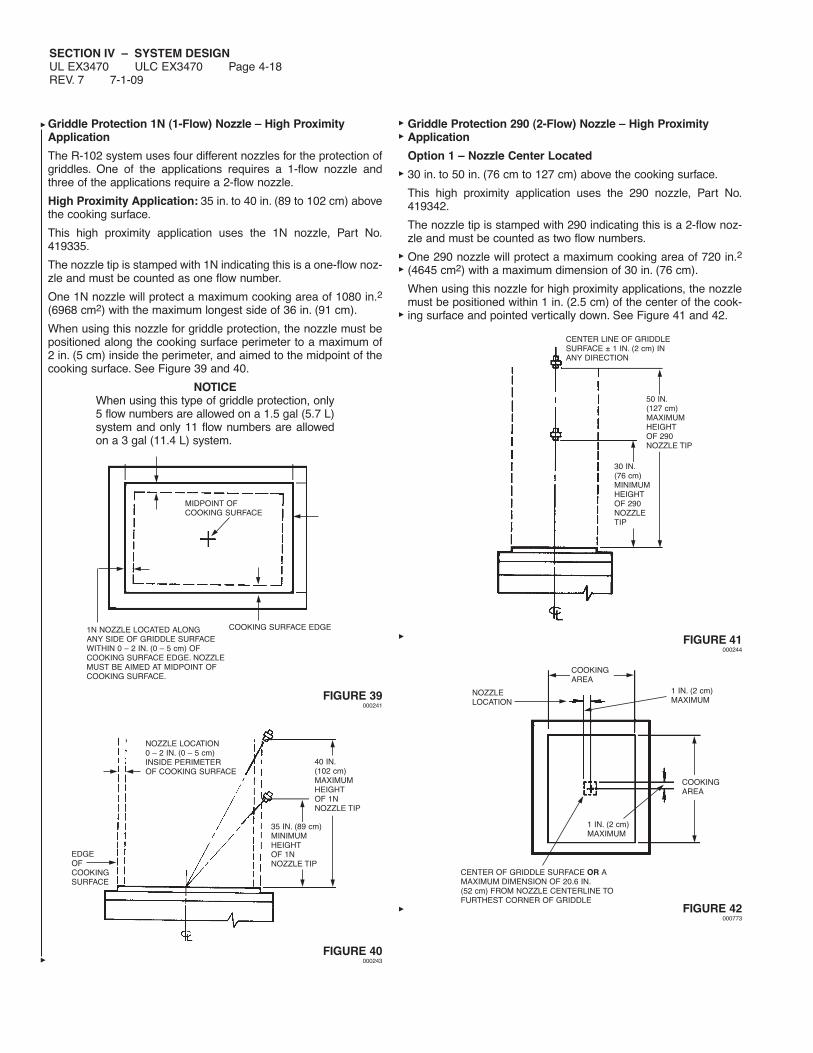
SECTION IV – SYSTEM DESIGNUL EX3470 ULC EX3470 Page 4-18REV. 7 7-1-09
Griddle Protection 1N (1-Flow) Nozzle – High ProximityApplication
The R-102 system uses four different nozzles for the protection ofgriddles. One of the applications requires a 1-flow nozzle andthree of the applications require a 2-flow nozzle.
High Proximity Application: 35 in. to 40 in. (89 to 102 cm) abovethe cooking surface.
This high proximity application uses the 1N nozzle, Part No.419335.
The nozzle tip is stamped with 1N indicating this is a one-flow noz-zle and must be counted as one flow number.
One 1N nozzle will protect a maximum cooking area of 1080 in.2(6968 cm2) with the maximum longest side of 36 in. (91 cm).
When using this nozzle for griddle protection, the nozzle must bepositioned along the cooking surface perimeter to a maximum of2 in. (5 cm) inside the perimeter, and aimed to the midpoint of thecooking surface. See Figure 39 and 40.
NOTICEWhen using this type of griddle protection, only5 flow numbers are allowed on a 1.5 gal (5.7 L)system and only 11 flow numbers are allowedon a 3 gal (11.4 L) system.
FIGURE 39000241
FIGURE 40000243
Griddle Protection 290 (2-Flow) Nozzle – High ProximityApplication
Option 1 – Nozzle Center Located
30 in. to 50 in. (76 cm to 127 cm) above the cooking surface.
This high proximity application uses the 290 nozzle, Part No.419342.
The nozzle tip is stamped with 290 indicating this is a 2-flow noz-zle and must be counted as two flow numbers.
One 290 nozzle will protect a maximum cooking area of 720 in.2(4645 cm2) with a maximum dimension of 30 in. (76 cm).
When using this nozzle for high proximity applications, the nozzlemust be positioned within 1 in. (2.5 cm) of the center of the cook-ing surface and pointed vertically down. See Figure 41 and 42.
FIGURE 41000244
FIGURE 42000773
NOZZLE LOCATION0 – 2 IN. (0 – 5 cm)INSIDE PERIMETEROF COOKING SURFACE
EDGEOFCOOKINGSURFACE
40 IN.(102 cm)MAXIMUMHEIGHTOF 1NNOZZLE TIP
35 IN. (89 cm)MINIMUMHEIGHTOF 1NNOZZLE TIP
MIDPOINT OFCOOKING SURFACE
1N NOZZLE LOCATED ALONGANY SIDE OF GRIDDLE SURFACEWITHIN 0 – 2 IN. (0 – 5 cm) OFCOOKING SURFACE EDGE. NOZZLEMUST BE AIMED AT MIDPOINT OFCOOKING SURFACE.
COOKING SURFACE EDGE
CENTER OF GRIDDLE SURFACE OR AMAXIMUM DIMENSION OF 20.6 IN.(52 cm) FROM NOZZLE CENTERLINE TOFURTHEST CORNER OF GRIDDLE
NOZZLELOCATION
COOKINGAREA
1 IN. (2 cm)MAXIMUM
COOKINGAREA
1 IN. (2 cm)MAXIMUM
CENTER LINE OF GRIDDLESURFACE ± 1 IN. (2 cm) INANY DIRECTION
50 IN.(127 cm)MAXIMUMHEIGHTOF 290NOZZLE TIP
30 IN.(76 cm)MINIMUMHEIGHTOF 290NOZZLETIP
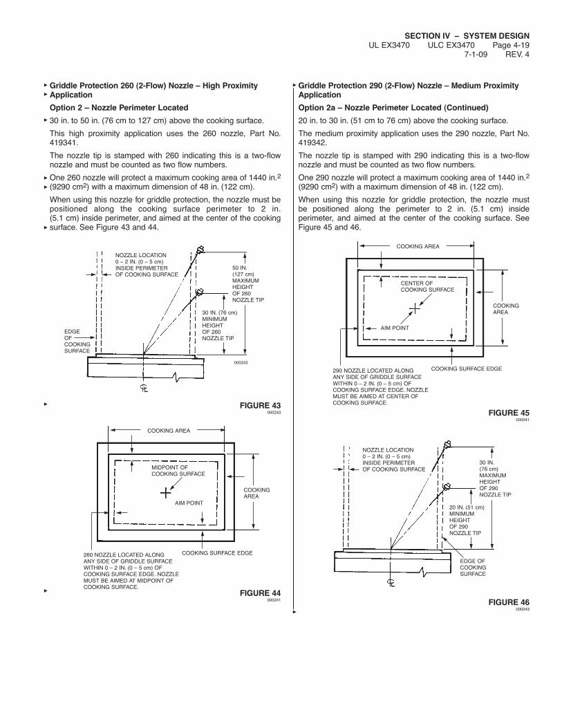
SECTION IV – SYSTEM DESIGNUL EX3470 ULC EX3470 Page 4-19
7-1-09 REV. 4
Griddle Protection 260 (2-Flow) Nozzle – High ProximityApplication
Option 2 – Nozzle Perimeter Located
30 in. to 50 in. (76 cm to 127 cm) above the cooking surface.
This high proximity application uses the 260 nozzle, Part No.419341.
The nozzle tip is stamped with 260 indicating this is a two-flownozzle and must be counted as two flow numbers.
One 260 nozzle will protect a maximum cooking area of 1440 in.2(9290 cm2) with a maximum dimension of 48 in. (122 cm).
When using this nozzle for griddle protection, the nozzle must bepositioned along the cooking surface perimeter to 2 in.(5.1 cm) inside perimeter, and aimed at the center of the cookingsurface. See Figure 43 and 44.
FIGURE 43000243
FIGURE 44000241
Griddle Protection 290 (2-Flow) Nozzle – Medium ProximityApplication
Option 2a – Nozzle Perimeter Located (Continued)
20 in. to 30 in. (51 cm to 76 cm) above the cooking surface.
The medium proximity application uses the 290 nozzle, Part No.419342.
The nozzle tip is stamped with 290 indicating this is a two-flownozzle and must be counted as two flow numbers.
One 290 nozzle will protect a maximum cooking area of 1440 in.2(9290 cm2) with a maximum dimension of 48 in. (122 cm).
When using this nozzle for griddle protection, the nozzle mustbe positioned along the perimeter to 2 in. (5.1 cm) insideperimeter, and aimed at the center of the cooking surface. SeeFigure 45 and 46.
FIGURE 45000241
FIGURE 46000243
COOKING AREA
CENTER OFCOOKING SURFACE
AIM POINT
COOKINGAREA
COOKING SURFACE EDGE290 NOZZLE LOCATED ALONGANY SIDE OF GRIDDLE SURFACEWITHIN 0 – 2 IN. (0 – 5 cm) OFCOOKING SURFACE EDGE. NOZZLEMUST BE AIMED AT CENTER OFCOOKING SURFACE.
NOZZLE LOCATION0 – 2 IN. (0 – 5 cm)INSIDE PERIMETEROF COOKING SURFACE
30 IN.(76 cm)MAXIMUMHEIGHTOF 290NOZZLE TIP
20 IN. (51 cm)MINIMUMHEIGHTOF 290NOZZLE TIP
EDGE OFCOOKINGSURFACE
000243
NOZZLE LOCATION0 – 2 IN. (0 – 5 cm)INSIDE PERIMETEROF COOKING SURFACE
EDGEOFCOOKINGSURFACE
30 IN. (76 cm)MINIMUMHEIGHTOF 260NOZZLE TIP
50 IN.(127 cm)MAXIMUMHEIGHTOF 260NOZZLE TIP
COOKING SURFACE EDGE
COOKINGAREA
AIM POINT
MIDPOINT OFCOOKING SURFACE
COOKING AREA
260 NOZZLE LOCATED ALONGANY SIDE OF GRIDDLE SURFACEWITHIN 0 – 2 IN. (0 – 5 cm) OFCOOKING SURFACE EDGE. NOZZLEMUST BE AIMED AT MIDPOINT OFCOOKING SURFACE.

SECTION IV – SYSTEM DESIGNUL EX3470 ULC EX3470 Page 4-20REV. 5 7-1-09
Griddle Protection 2120 (2-Flow) Nozzle – Low ProximityApplication
Option 2b – Nozzle Perimeter Located (Continued)
10 in. to 20 in. (25 cm to 51 cm) above the cooking surface.
The low proximity application uses the 2120 nozzle, Part No.419343.
The nozzle tip is stamped with 2120 indicating this is a two-flownozzle and must be counted as two flow numbers.
One 2120 nozzle will protect a maximum cooking area of 1440 in.2(9290 cm2) with a maximum dimension of 48 in. (122 cm).
When using this nozzle for griddle protection, the nozzle mustbe positioned along the perimeter to 2 in. (5.1 cm) inside perime-ter, and aimed at the center of the cooking surface. See Figure47 and 48.
FIGURE 47000243
FIGURE 48000241
Griddle Protection 2W (2-Flow) Nozzle – Low ProximityApplication
Option 2c – Nozzle Perimeter Located (Continued)
10 in. to 20 in. (25 cm to 51 cm) above the cooking surface.
The low proximity application uses the 2W nozzle, Part No.419337.
The nozzle tip is stamped with 2W indicating this is a two-flow noz-zle and must be counted as two flow numbers.
One 2W nozzle will protect a maximum cooking area of 1080 in.2(6967.7 cm2) with a maximum dimension of 36 in. (91.4 cm).
When using this nozzle for griddle protection, the nozzle must bepositioned along the perimeter to 9 in. (22.9 cm) inside perimeter,and aimed at the center of the cooking surface. See Figure 49 and50.
FIGURE 49
FIGURE 50
000243
NOZZLE LOCATION0 – 2 IN. (0 – 5 cm)INSIDE PERIMETEROF COOKING SURFACE
20 IN.(51 cm)MAXIMUMHEIGHTOF 2120NOZZLE TIP
10 IN. (25 cm)MINIMUMHEIGHTOF 2120NOZZLE TIP
EDGE OFCOOKING SURFACE
COOKING AREA
CENTER OFCOOKING SURFACE
AIM POINT
COOKINGAREA
COOKING SURFACE EDGE2120 NOZZLE LOCATED ALONGANY SIDE OF GRIDDLE SURFACEWITHIN 0 – 2 IN. (0 – 5 cm) OFCOOKING SURFACE EDGE. NOZZLEMUST BE AIMED AT CENTER OFCOOKING SURFACE.
CL
2W NOZZLE AIM POINT 0-3 IN. (0-7.6 cm) TO REAR OFCOOKING SURFACE CENTERLINE WHEN 2W NOZZLE ISPOSITIONED AT OR TO THEREAR OF CENTER LINE
NOTE: A 2W NOZZLE CAN PROTECT A GRIDDLEWITH A MAXIMUM COOKING SURFACEOF 30 IN X 36 IN. (76.2 cm X 91.4 cm), AT AHEIGHT OF 10 - 20 IN. (25.4 - 50.8 cm).
THE 2W NOZZLE CAN BE POSITIONED AMAXIMUM OF ± 10 IN. (25.4 cm) FOR-WARD OR BEHIND COOKING SURFACECENTER LINE AND A MAXIMUM OF 3 IN.(7.6 cm) AWAY FROM EITHER SIDE OFTHE COOKING SURFACE, AIMED IN 9 IN.(22.9 cm) TO A POINT 0 - 3 IN. (0 - 22.0cm). FORWARD OR TO THE REAR OFTHE COOKING SURFACE CENTER LINE.
2W NOZZLE AIM POINT 0-3 IN. (0-7.6 cm) FORWARDOF COOKING SURFACE CEN-TER LINE WHEN 2W NOZZLEIS POSITIONED AT OR FOR-WARD OF COOKING SURFACECENTER LINE
36 IN. (91.4 cm) MAX.
0 - 3 IN. (76.2 cm)
30 IN.(76.2 cm)
MAX.
10 IN.(25.4 cm)
MIN.
AIM POINT 9 IN. (22.9 cm)FROM EITHER SIDE OFCOOKING SURFACE
AIM POINT 9 IN.(22.9 cm) FROMEITHER SIDE OF
COOKING SURFACE
0 - 10 IN.(0 - 25.4 cm) FROM
CENTERLINEMAX.
0 - 10 IN.(0 - 25.4 cm) FROM
CENTERLINEMAX.
20 IN.(50.8 cm)
MAX.
008149
008150
OVERHEAD VIEW
FRONT VIEW
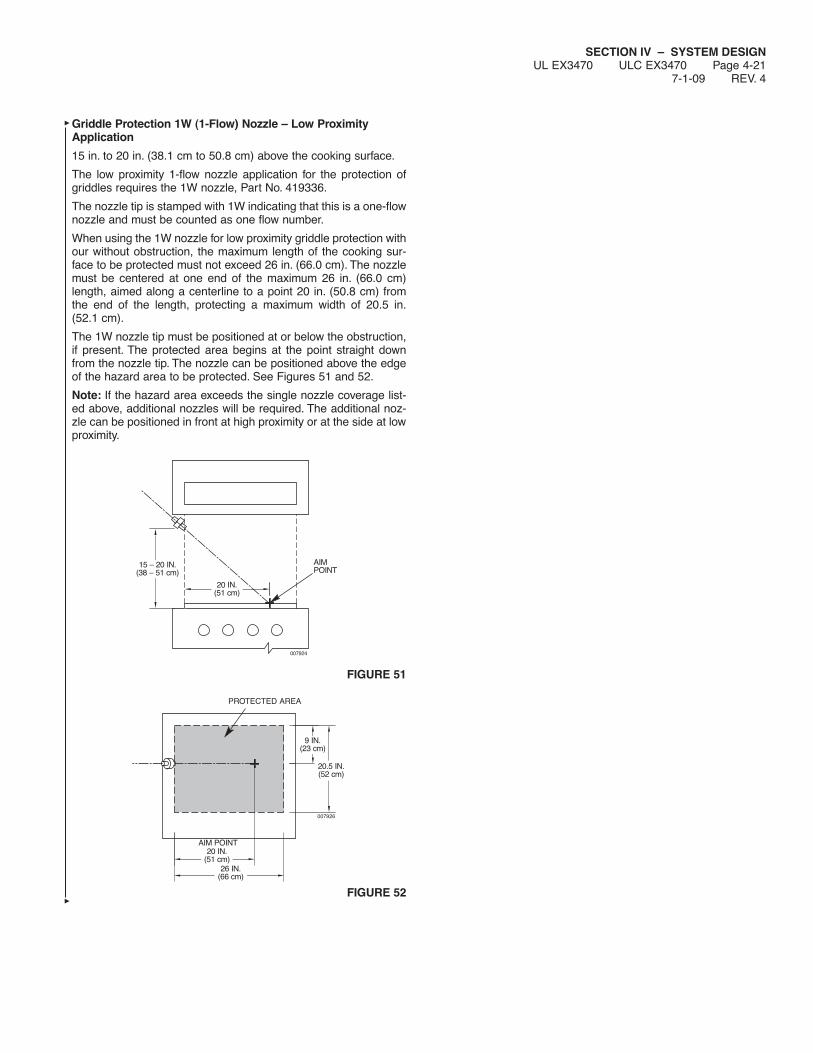
SECTION IV – SYSTEM DESIGNUL EX3470 ULC EX3470 Page 4-21
7-1-09 REV. 4
Griddle Protection 1W (1-Flow) Nozzle – Low ProximityApplication
15 in. to 20 in. (38.1 cm to 50.8 cm) above the cooking surface.
The low proximity 1-flow nozzle application for the protection ofgriddles requires the 1W nozzle, Part No. 419336.
The nozzle tip is stamped with 1W indicating that this is a one-flownozzle and must be counted as one flow number.
When using the 1W nozzle for low proximity griddle protection withour without obstruction, the maximum length of the cooking sur-face to be protected must not exceed 26 in. (66.0 cm). The nozzlemust be centered at one end of the maximum 26 in. (66.0 cm)length, aimed along a centerline to a point 20 in. (50.8 cm) fromthe end of the length, protecting a maximum width of 20.5 in.(52.1 cm).
The 1W nozzle tip must be positioned at or below the obstruction,if present. The protected area begins at the point straight downfrom the nozzle tip. The nozzle can be positioned above the edgeof the hazard area to be protected. See Figures 51 and 52.
Note: If the hazard area exceeds the single nozzle coverage list-ed above, additional nozzles will be required. The additional noz-zle can be positioned in front at high proximity or at the side at lowproximity.
FIGURE 51
FIGURE 52
15 – 20 IN.(38 – 51 cm)
20 IN.(51 cm)
007924
AIM POINT
26 IN.(66 cm)
20 IN.(51 cm)
20.5 IN.(52 cm)
007926
AIM POINT
9 IN.(23 cm)
PROTECTED AREA
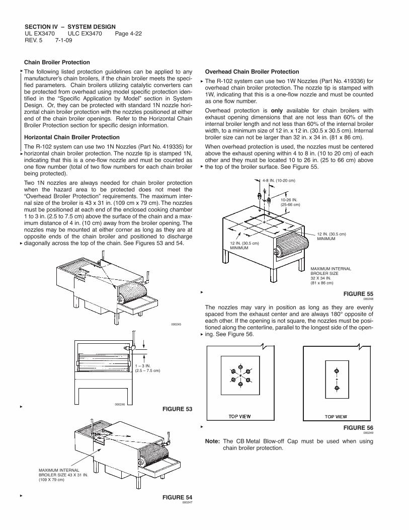
SECTION IV – SYSTEM DESIGNUL EX3470 ULC EX3470 Page 4-22REV. 5 7-1-09
Chain Broiler Protection
The following listed protection guidelines can be applied to anymanufacturer’s chain broilers, if the chain broiler meets the speci-fied parameters. Chain broilers utilizing catalytic converters canbe protected from overhead using model specific protection iden-tified in the “Specific Application by Model” section in SystemDesign. Or, they can be protected with standard 1N nozzle hori-zontal chain broiler protection with the nozzles positioned at eitherend of the chain broiler openings. Refer to the Horizontal ChainBroiler Protection section for specific design information.
Horizontal Chain Broiler Protection
The R-102 system can use two 1N Nozzles (Part No. 419335) forhorizontal chain broiler protection. The nozzle tip is stamped 1N,indicating that this is a one-flow nozzle and must be counted asone flow number (total of two flow numbers for each chain broilerbeing protected).
Two 1N nozzles are always needed for chain broiler protectionwhen the hazard area to be protected does not meet the“Overhead Broiler Protection” requirements. The maximum inter-nal size of the broiler is 43 x 31 in. (109 cm x 79 cm). The nozzlesmust be positioned at each end of the enclosed cooking chamber1 to 3 in. (2.5 to 7.5 cm) above the surface of the chain and a max-imum distance of 4 in. (10 cm) away from the broiler opening. Thenozzles may be mounted at either corner as long as they are atopposite ends of the chain broiler and positioned to dischargediagonally across the top of the chain. See Figures 53 and 54.
000245
FIGURE 53
FIGURE 54000247
Overhead Chain Broiler Protection
The R-102 system can use two 1W Nozzles (Part No. 419336) foroverhead chain broiler protection. The nozzle tip is stamped with1W, indicating that this is a one-flow nozzle and must be countedas one flow number.
Overhead protection is only available for chain broilers withexhaust opening dimensions that are not less than 60% of theinternal broiler length and not less than 60% of the internal broilerwidth, to a minimum size of 12 in. x 12 in. (30.5 x 30.5 cm). Internalbroiler size can not be larger than 32 in. x 34 in. (81 x 86 cm).
When overhead protection is used, the nozzles must be centeredabove the exhaust opening within 4 to 8 in. (10 to 20 cm) of eachother and they must be located 10 to 26 in. (25 to 66 cm) abovethe top of the broiler surface. See Figure 55.
FIGURE 55000248
The nozzles may vary in position as long as they are evenlyspaced from the exhaust center and are always 180° opposite ofeach other. If the opening is not square, the nozzles must be posi-tioned along the centerline, parallel to the longest side of the open-ing. See Figure 56.
FIGURE 56000249
Note: The CB Metal Blow-off Cap must be used when usingchain broiler protection.
1 – 3 IN.(2.5 – 7.5 cm)
MAXIMUM INTERNALBROILER SIZE 43 X 31 IN.(109 X 79 cm)
000246
4-8 IN. (10-20 cm)
10-26 IN.(25-66 cm)
12 IN. (30.5 cm)MINIMUM
12 IN. (30.5 cm)MINIMUM
MAXIMUM INTERNALBROILER SIZE32 X 34 IN.(81 x 86 cm)
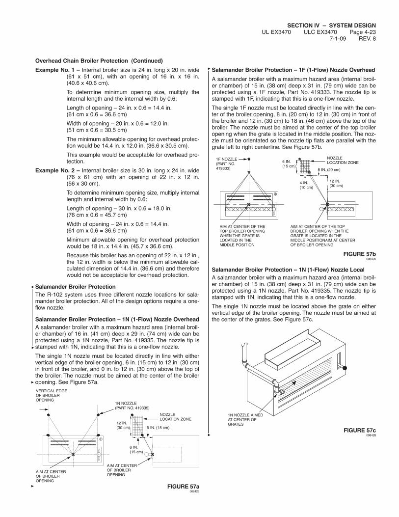
SECTION IV – SYSTEM DESIGNUL EX3470 ULC EX3470 Page 4-23
7-1-09 REV. 8
Overhead Chain Broiler Protection (Continued)
Example No. 1 – Internal broiler size is 24 in. long x 20 in. wide(61 x 51 cm), with an opening of 16 in. x 16 in.(40.6 x 40.6 cm).
To determine minimum opening size, multiply theinternal length and the internal width by 0.6:
Length of opening – 24 in. x 0.6 = 14.4 in.(61 cm x 0.6 = 36.6 cm)
Width of opening – 20 in. x 0.6 = 12.0 in.(51 cm x 0.6 = 30.5 cm)
The minimum allowable opening for overhead protec-tion would be 14.4 in. x 12.0 in. (36.6 x 30.5 cm).
This example would be acceptable for overhead pro-tection.
Example No. 2 – Internal broiler size is 30 in. long x 24 in. wide(76 x 61 cm) with an opening of 22 in. x 12 in.(56 x 30 cm).
To determine minimum opening size, multiply internallength and internal width by 0.6:
Length of opening – 30 in. x 0.6 = 18.0 in.(76 cm x 0.6 = 45.7 cm)
Width of opening – 24 in. x 0.6 = 14.4 in.(61 cm x 0.6 = 36.6 cm)
Minimum allowable opening for overhead protectionwould be 18 in. x 14.4 in. (45.7 x 36.6 cm).
Because this broiler has an opening of 22 in. x 12 in.,the 12 in. width is below the minimum allowable cal-culated dimension of 14.4 in. (36.6 cm) and thereforewould not be acceptable for overhead protection.
Salamander Broiler ProtectionThe R-102 system uses three different nozzle locations for sala-mander broiler protection. All of the design options require a one-flow nozzle.
Salamander Broiler Protection – 1N (1-Flow) Nozzle OverheadA salamander broiler with a maximum hazard area (internal broil-er chamber) of 16 in. (41 cm) deep x 29 in. (74 cm) wide can beprotected using a 1N nozzle, Part No. 419335. The nozzle tip isstamped with 1N, indicating that this is a one-flow nozzle.
The single 1N nozzle must be located directly in line with eithervertical edge of the broiler opening, 6 in. (15 cm) to 12 in. (30 cm)in front of the broiler, and 0 in. to 12 in. (30 cm) above the top ofthe broiler. The nozzle must be aimed at the center of the broileropening. See Figure 57a.
FIGURE 57a008426
Salamander Broiler Protection – 1F (1-Flow) Nozzle Overhead
A salamander broiler with a maximum hazard area (internal broil-er chamber) of 15 in. (38 cm) deep x 31 in. (79 cm) wide can beprotected using a 1F nozzle, Part No. 419333. The nozzle tip isstamped with 1F, indicating that this is a one-flow nozzle.
The single 1F nozzle must be located directly in line with the cen-ter of the broiler opening, 8 in. (20 cm) to 12 in. (30 cm) in front ofthe broiler and 12 in. (30 cm) to 18 in. (46 cm) above the top of thebroiler. The nozzle must be aimed at the center of the top broileropening when the grate is located in the middle position. The noz-zle must be orientated so the nozzle tip flats are parallel with thegrate left to right centerline. See Figure 57b.
FIGURE 57b008426
Salamander Broiler Protection – 1N (1-Flow) Nozzle LocalA salamander broiler with a maximum hazard area (internal broil-er chamber) of 15 in. (38 cm) deep x 31 in. (79 cm) wide can beprotected using a 1N nozzle, Part No. 419335. The nozzle tip isstamped with 1N, indicating that this is a one-flow nozzle.
The single 1N nozzle must be located above the grate on eithervertical edge of the broiler opening. The nozzle must be aimed atthe center of the grates. See Figure 57c.
FIGURE 57c008428
AIM AT CENTEROF BROILEROPENING
AIM AT CENTEROF BROILEROPENING
VERTICAL EDGEOF BROILEROPENING
NOZZLELOCATION ZONE
1N NOZZLE(PART NO. 419335)
6 IN.(15 cm)
6 IN. (15 cm)12 IN.(30 cm)
AIM AT CENTER OF THE TOPBROILER OPENING WHEN THEGRATE IS LOCATED IN THEMIDDLE POSITIONAIM AT CENTEROF BROILER OPENING
AIM AT CENTER OF THETOP BROILER OPENINGWHEN THE GRATE ISLOCATED IN THEMIDDLE POSITION
NOZZLELOCATION ZONE
1F NOZZLE(PART NO.419333)
6 IN.(15 cm)
8 IN. (20 cm)
4 IN.(10 cm)
12 IN.(30 cm)
1N NOZZLE AIMEDAT CENTER OFGRATES

SECTION IV – SYSTEM DESIGNUL EX3470 ULC EX3470 Page 4-24REV. 7 7-1-09
Upright Broiler Protection
The R-102 system uses two 1/2N Nozzles (Part No. 419334) for allupright broiler protection. The nozzle tip is stamped 1/2N, indicat-ing that this is a half-flow nozzle. A pair of these nozzles will equalone flow number.
Two 1/2N nozzles will protect a maximum hazard area (internalbroiler chamber) of 30 in. x 32.5 in. (76 cm x 82.5 cm). These noz-zles must always be used in pairs on an upright broiler. One noz-zle must be positioned above the grate and pointed at the backopposite corner of the broiler chamber. The second nozzle mustbe pointed down into the center of the drip pan through the openslot. See Figure 58.
FIGURE 58
Gas-Radiant/Electric Char-Broiler Protection
The R-102 system uses the 1N nozzle, (Part No. 419335) for gas-radiant/electric char-broiler protection.
The nozzle tip on the 1N nozzle is stamped with a 1N, indicatingthat this is a one-flow nozzle and must be counted as one flownumber.
One IN nozzle will protect a hazard with a maximum length of36 in. (91 cm) and a total cooking area which does not exceed864 in.2 (5574 cm2). The nozzle tip must be located 15 to40 in. (38 to 102 cm) above the hazard surface. When using thisnozzle for gas-radiant/electric char-broiler protection, the nozzlemust be positioned anywhere along or within the perimeter of themaximum cooking area and shall be aimed at the center of thecooking surface. See Figure 59.
FIGURE 59
000256
000257
COOKINGAREA
COOKINGAREA
40 IN.(102 cm)MAXIMUM
15 IN. (38 cm)MINIMUM
000252
UPRIGHT BROILER
BROILER CHAMBER
FRONT VIEW
DRIPPAN
SIDE VIEW

SECTION IV – SYSTEM DESIGNUL EX3470 ULC EX3470 Page 4-25
7-1-09 REV. 7
Lava Rock (Ceramic) Char-Broiler Protection
The R-102 system uses the 1N Nozzle (Part No. 419335) for alllava rock char-broiler protection. The nozzle tip is stamped with1N, indicating that this is a one-flow nozzle and must be countedas one flow number.
One 1N nozzle will protect a hazard which has a maximum lengthof 24 in. (61 cm) and a total cooking area which does not exceed312 in.2 (2013 cm2).The nozzle tip must be located 18 to 35 in. (46to 89 cm) above the hazard surface. When using this nozzle forlava rock (ceramic) char-broiler protection, the nozzle must bepositioned anywhere along or within the perimeter of the maximumcooking area and angled to the center. See Figure 60.
FIGURE 60
Natural Charcoal Broiler Protection
The R-102 system uses the 1N Nozzle (Part No. 419335) for allnatural charcoal broiler protection. The nozzle tip is stamped with1N indicating that this is a one-flow nozzle and must be countedas one flow number.
One 1N nozzle will protect a hazard area which has a maximumlength of 24 in. (61 cm) and a total cooking area which does notexceed 288 in.2 (1858 cm2). The nozzle tip must be located 18 to40 in. (46 to 102 cm) above the hazard surface. When using thisnozzle for natural charcoal broiler protection, the nozzle must bepositioned anywhere along or within the perimeter of the maximumcooking area and aimed at the center of the cooking surface. SeeFigure 61.
The coverage of such appliances only applies when the depth ofthe charcoal does not exceed 4 in. (10 cm).
FIGURE 61
000259
COOKINGAREA COOKING
AREA
35 IN.(89 cm)MAXIMUM
18 IN.(46 cm)MINIMUM
COOKINGAREA COOKING
AREA
000260
000258
4 IN. (10 cm)MAXIMUMDEPTH
18 IN.(46 cm)MINIMUM
40 IN.(102 cm)MAXIMUM
000259
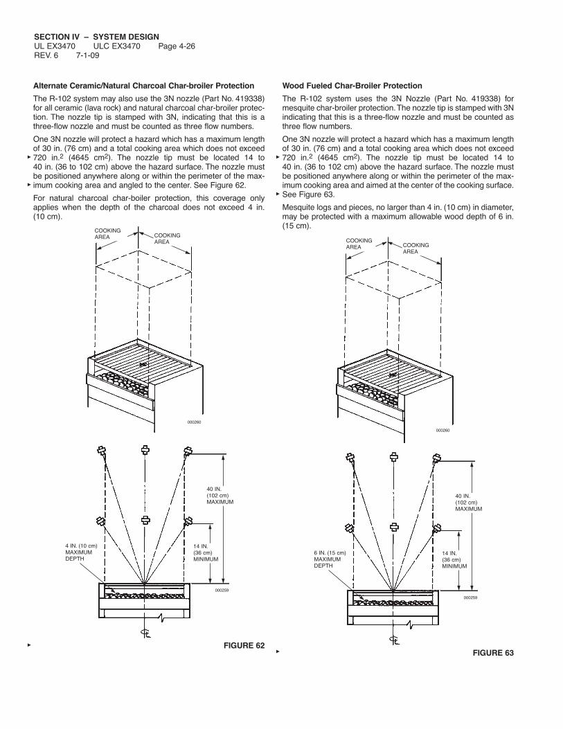
SECTION IV – SYSTEM DESIGNUL EX3470 ULC EX3470 Page 4-26REV. 6 7-1-09
Alternate Ceramic/Natural Charcoal Char-broiler Protection
The R-102 system may also use the 3N nozzle (Part No. 419338)for all ceramic (lava rock) and natural charcoal char-broiler protec-tion. The nozzle tip is stamped with 3N, indicating that this is athree-flow nozzle and must be counted as three flow numbers.
One 3N nozzle will protect a hazard which has a maximum lengthof 30 in. (76 cm) and a total cooking area which does not exceed720 in.2 (4645 cm2). The nozzle tip must be located 14 to40 in. (36 to 102 cm) above the hazard surface. The nozzle mustbe positioned anywhere along or within the perimeter of the max-imum cooking area and angled to the center. See Figure 62.
For natural charcoal char-boiler protection, this coverage onlyapplies when the depth of the charcoal does not exceed 4 in.(10 cm).
FIGURE 62
Wood Fueled Char-Broiler Protection
The R-102 system uses the 3N Nozzle (Part No. 419338) formesquite char-broiler protection.The nozzle tip is stamped with 3Nindicating that this is a three-flow nozzle and must be counted asthree flow numbers.
One 3N nozzle will protect a hazard which has a maximum lengthof 30 in. (76 cm) and a total cooking area which does not exceed720 in.2 (4645 cm2). The nozzle tip must be located 14 to40 in. (36 to 102 cm) above the hazard surface. The nozzle mustbe positioned anywhere along or within the perimeter of the max-imum cooking area and aimed at the center of the cooking surface.See Figure 63.
Mesquite logs and pieces, no larger than 4 in. (10 cm) in diameter,may be protected with a maximum allowable wood depth of 6 in.(15 cm).
FIGURE 63
COOKINGAREA COOKING
AREA
000260
40 IN.(102 cm)MAXIMUM
14 IN.(36 cm)MINIMUM
4 IN. (10 cm)MAXIMUMDEPTH
000259
COOKINGAREA COOKING
AREA
000260
6 IN. (15 cm)MAXIMUMDEPTH
40 IN.(102 cm)MAXIMUM
14 IN.(36 cm)MINIMUM
000259

SECTION IV – SYSTEM DESIGNUL EX3470 ULC EX3470 Page 4-27
7-1-09 REV. 5
Wok Protection
The R-102 system uses two different nozzles for the protection ofwoks.
1. A 260 nozzle, Part No. 419341, will protect a wok 14 in.(36 cm) minimum diameter up to 30 in. (76 cm) maximumdiameter. The wok depth must be no less than 3.75 in.(9.5 cm) and no greater than 8 in. (20 cm).
The nozzle tip is stamped with 260 indicating that this is a two-flow nozzle and must be counted as two flow numbers.
When using this nozzle, the nozzle must be positioned asshown in Figure 64.
FIGURE 64000261
2. A 1N Nozzle, Part No. 419335, will protect a wok 11 in. (28 cm)minimum diameter up to 24 in. (61 cm) maximum diameter.The wok depth must be no less than 3 in. (8 cm) and nogreater than 6 in. (15 cm). The nozzle tip is stamped with 1Nindicating that this a one-flow nozzle and must be counted asone flow number. When using this nozzle, the nozzle must bepositioned anywhere along or within the perimeter of the wok,aimed at the center, 30 in. to 40 in. (76 to 102 cm) above thehazard surface, as shown in Figure 65.
NOTICEWhen using this type of wok protection, only5 flow numbers are allowed on a 1 1/2 gal(5.7 L) system, and only 11 flow numbers areallowed on a 3 gal (11.4 L) system.
FIGURE 65000261
NOZZLE MUST BE POSITIONED WITHIN 1 IN. (2 cm) RADIUSOF THE CENTER OF THE WOK, POINTED VERTICALLY DOWN
260 NOZZLE
MINIMUM DEPTH 3.75 IN. (9.6 cm)MAXIMUM DEPTH 8 IN. (20 cm)
35 – 45 IN.(89 – 114 cm)
14 IN. (35.6 cm) MINIMUM DIAMETER30 IN. (76.2 cm) MAXIMUM DIAMETER
MINIMUM DEPTH3.0 IN. (7.6 cm)MAXIMUM DEPTH6.0 IN. (15 cm)
11 IN. (28 cm) MINIMUM DIAMETER24 IN. (61 cm) MAXIMUM DIAMETER
40 IN.(102 cm)
30 IN.(76 cm)

SECTION IV – SYSTEM DESIGNUL EX3470 ULC EX3470 Page 4-28REV. 6 7-1-09
Nozzle Application Chart
The following chart has been developed to assist in calculating thequantity and type of nozzle required to protect each duct, plenum,or appliance.
NOTICEThis chart is for general reference only. Seecomplete details for each type of hazard.
Minimum Nozzle TipMaximum Hazard Nozzle Nozzle Nozzle Stamping –
Hazard Dimensions Quantity Heights Part No. Flow No.
Duct or Transition Length – Unlimited 1 – 430912 1W(Single Nozzle) Perimeter – 50 in. (127 cm)
Diameter – 16 in. (40.6 cm)
Duct or Transition Length – Unlimited 1 – 419337 2W(Single Nozzle) Perimeter – 100 in. (254 cm)
Diameter – 31 7/8 in. (81 cm)
Duct or Transition Length – Unlimited 2 – 419337 2W(Dual Nozzle) Perimeter – 150 in. (381 cm)
Diameter – 48 in. (122 cm)
Electrostatic Precipitator Individual Cell 1 – 419334 1/2N(At Base of Duct)
Plenum Length – 10 ft (3.1 m) 1 – 419335 1N(Horizontal Protection)
Plenum Length – 6 ft (1.8 m) 1 – 430192 1W(Horizontal Protection) Width – 4 ft (1.2 m) 1 – 419336 1W
Plenum Length – 4 ft (1.2 m) 1 – 419336 1W(Vertical Protection) Width – 4 ft (1.2 m)
Fryer (Split or Maximum SizeNon-Split Vat) (without drip board)
14 in. (36 cm) x 15 in. (38 cm) 1 13 – 16 in. 419342 290
Low Proximity (33 – 41 cm)
Fryer (Split or Maximum SizeNon-Split Vat) (without drip board)
14 1/2 in. (37 cm) x 14 in. (36 cm) 1 16 – 27 in. 419342 290
Medium Proximity (41 – 69 cm)
Fryer (Split or Maximum SizeNon-Split Vat)* (without drip board)
15 in. (38 cm) x 14 in. (36 cm)
High Proximity 1 27 – 47 in. 419339 230Medium Proximity 1 20 – 27 in. 419340 245
Fryer (Non-Split Vat Only) Maximum Size (without drip board)19 1/2 in. (49.5 cm) x 19 in. (48.2 cm)
High Proximity 1 21 – 34 in. 419338 3NLow Proximity 1 13 – 16 in. 419342 290
Maximum Size (without drip board)18 in. (45.7 cm)x 18 in. (45.7 cm)
High Proximity 1 25 – 35 in. 419338 3N(64-89 cm)
* For multiple nozzle protection of single fryers, see detailed information on Pages 4-10 and 4-11.
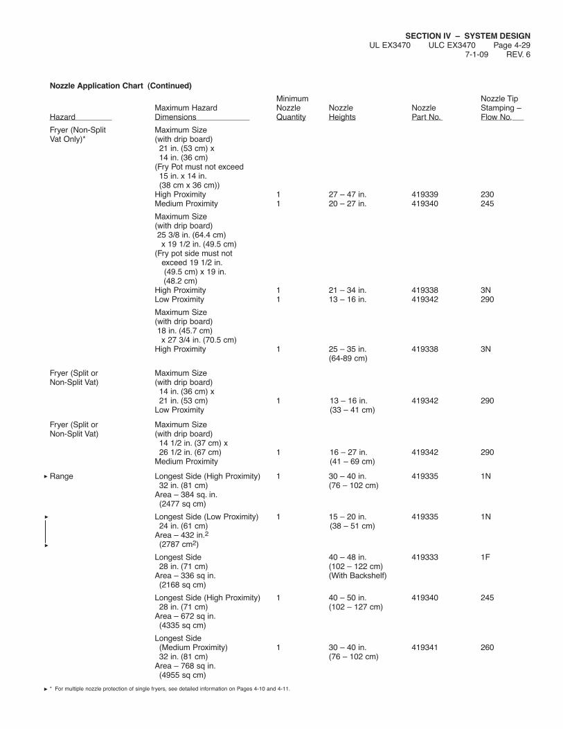
Nozzle Application Chart (Continued)
Minimum Nozzle TipMaximum Hazard Nozzle Nozzle Nozzle Stamping –
Hazard Dimensions Quantity Heights Part No. Flow No.
Fryer (Non-Split Maximum Size Vat Only)* (with drip board)
21 in. (53 cm) x 14 in. (36 cm)
(Fry Pot must not exceed 15 in. x 14 in.(38 cm x 36 cm))
High Proximity 1 27 – 47 in. 419339 230Medium Proximity 1 20 – 27 in. 419340 245
Maximum Size (with drip board)25 3/8 in. (64.4 cm)x 19 1/2 in. (49.5 cm)
(Fry pot side must notexceed 19 1/2 in.(49.5 cm) x 19 in.(48.2 cm)
High Proximity 1 21 – 34 in. 419338 3NLow Proximity 1 13 – 16 in. 419342 290
Maximum Size (with drip board)18 in. (45.7 cm)x 27 3/4 in. (70.5 cm)
High Proximity 1 25 – 35 in. 419338 3N(64-89 cm)
Fryer (Split or Maximum SizeNon-Split Vat) (with drip board)
14 in. (36 cm) x 21 in. (53 cm) 1 13 – 16 in. 419342 290
Low Proximity (33 – 41 cm)
Fryer (Split or Maximum SizeNon-Split Vat) (with drip board)
14 1/2 in. (37 cm) x 26 1/2 in. (67 cm) 1 16 – 27 in. 419342 290
Medium Proximity (41 – 69 cm)
Range Longest Side (High Proximity) 1 30 – 40 in. 419335 1N32 in. (81 cm) (76 – 102 cm)
Area – 384 sq. in.(2477 sq cm)
Longest Side (Low Proximity) 1 15 – 20 in. 419335 1N24 in. (61 cm) (38 – 51 cm)
Area – 432 in.2(2787 cm2)
Longest Side 40 – 48 in. 419333 1F28 in. (71 cm) (102 – 122 cm)
Area – 336 sq in. (With Backshelf)(2168 sq cm)
Longest Side (High Proximity) 1 40 – 50 in. 419340 24528 in. (71 cm) (102 – 127 cm)
Area – 672 sq in.(4335 sq cm)
Longest Side (Medium Proximity) 1 30 – 40 in. 419341 26032 in. (81 cm) (76 – 102 cm)
Area – 768 sq in.(4955 sq cm)
* For multiple nozzle protection of single fryers, see detailed information on Pages 4-10 and 4-11.
SECTION IV – SYSTEM DESIGNUL EX3470 ULC EX3470 Page 4-29
7-1-09 REV. 6
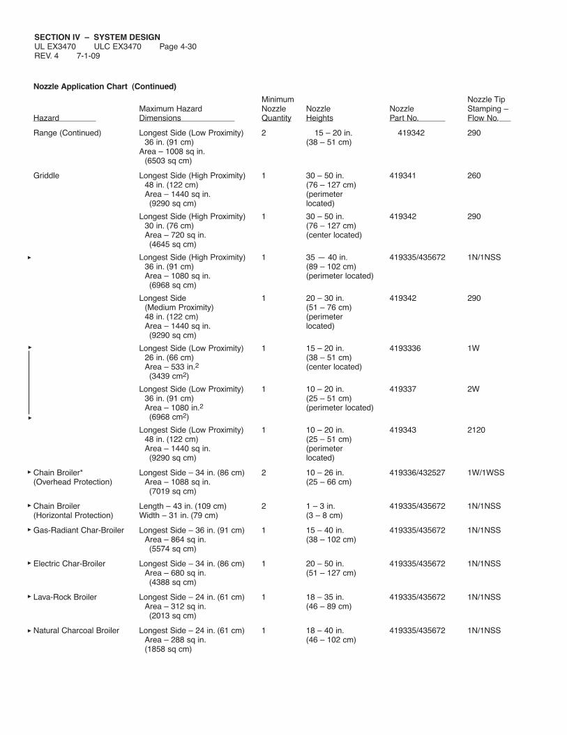
SECTION IV – SYSTEM DESIGNUL EX3470 ULC EX3470 Page 4-30REV. 4 7-1-09
Nozzle Application Chart (Continued)
Minimum Nozzle TipMaximum Hazard Nozzle Nozzle Nozzle Stamping –
Hazard Dimensions Quantity Heights Part No. Flow No.
Range (Continued) Longest Side (Low Proximity) 2 15 – 20 in. 419342 29036 in. (91 cm) (38 – 51 cm)
Area – 1008 sq in.(6503 sq cm)
Griddle Longest Side (High Proximity) 1 30 – 50 in. 419341 26048 in. (122 cm) (76 – 127 cm)Area – 1440 sq in. (perimeter(9290 sq cm) located)
Longest Side (High Proximity) 1 30 – 50 in. 419342 29030 in. (76 cm) (76 – 127 cm)Area – 720 sq in. (center located)(4645 sq cm)
Longest Side (High Proximity) 1 35 — 40 in. 419335/435672 1N/1NSS36 in. (91 cm) (89 – 102 cm)Area – 1080 sq in. (perimeter located)(6968 sq cm)
Longest Side 1 20 – 30 in. 419342 290(Medium Proximity) (51 – 76 cm)48 in. (122 cm) (perimeterArea – 1440 sq in. located)(9290 sq cm)
Longest Side (Low Proximity) 1 15 – 20 in. 4193336 1W26 in. (66 cm) (38 – 51 cm)Area – 533 in.2 (center located)(3439 cm2)
Longest Side (Low Proximity) 1 10 – 20 in. 419337 2W36 in. (91 cm) (25 – 51 cm)Area – 1080 in.2 (perimeter located)(6968 cm2)
Longest Side (Low Proximity) 1 10 – 20 in. 419343 212048 in. (122 cm) (25 – 51 cm)Area – 1440 sq in. (perimeter(9290 sq cm) located)
Chain Broiler* Longest Side – 34 in. (86 cm) 2 10 – 26 in. 419336/432527 1W/1WSS(Overhead Protection) Area – 1088 sq in. (25 – 66 cm)
(7019 sq cm)
Chain Broiler Length – 43 in. (109 cm) 2 1 – 3 in. 419335/435672 1N/1NSS(Horizontal Protection) Width – 31 in. (79 cm) (3 – 8 cm)
Gas-Radiant Char-Broiler Longest Side – 36 in. (91 cm) 1 15 – 40 in. 419335/435672 1N/1NSSArea – 864 sq in. (38 – 102 cm)(5574 sq cm)
Electric Char-Broiler Longest Side – 34 in. (86 cm) 1 20 – 50 in. 419335/435672 1N/1NSSArea – 680 sq in. (51 – 127 cm)(4388 sq cm)
Lava-Rock Broiler Longest Side – 24 in. (61 cm) 1 18 – 35 in. 419335/435672 1N/1NSSArea – 312 sq in. (46 – 89 cm)(2013 sq cm)
Natural Charcoal Broiler Longest Side – 24 in. (61 cm) 1 18 – 40 in. 419335/435672 1N/1NSSArea – 288 sq in. (46 – 102 cm)(1858 sq cm)

SECTION IV – SYSTEM DESIGNUL EX3470 ULC EX3470 Page 4-31
7-1-09 REV. 7
Nozzle Application Chart (Continued)
Minimum Nozzle TipMaximum Hazard Nozzle Nozzle Nozzle Stamping –
Hazard Dimensions Quantity Heights Part No. Flow No.
Lava-Rock or Natural Longest Side – 30 in. (76 cm) 1 14 – 40 in. 419338 3NCharcoal Char-Broiler Area – 720 sq in. (36 – 102 cm)
(4645 sq cm)
Wood Fueled Char-Broiler Longest Side – 30 in. (76 cm) 1 14 – 40 in. 419338 3NArea – 720 sq in. (36 – 102 cm)(4645 sq cm)
Upright Broiler Length – 32.5 in. (82.5 cm) 2 – 419334 1/2NWidth – 30 in. (76 cm)
Salamander Length – 29 in. (74 cm) 1 – 419335 1NBroiler Width – 16 in. (41 cm)
Length – 31 in. (79 cm) 1 – 419333 1FWidth – 15 in. (38 cm)
Length – 31 in. (79 cm) 1 – 419335 1NWidth – 15 in. (38 cm)
Wok 14 in. – 30 in. (36 – 76 cm) 1 35 – 45 in. 419341 260Diameter (89 – 114 cm)3.75 – 8.0 in. (9.5 – 20 cm)Deep
11 in. – 24 in. (28 – 61 cm) 30 – 40 in. 419335/435672 1N/1NSSDiameter (76 – 102 cm)3.0 – 6.0 in. (8 – 15.2 cm)Deep
* Minimum chain broiler exhaust opening – 12 in. x 12 in. (31 cm x 31 cm), and not less than 60% of internal broiler size.
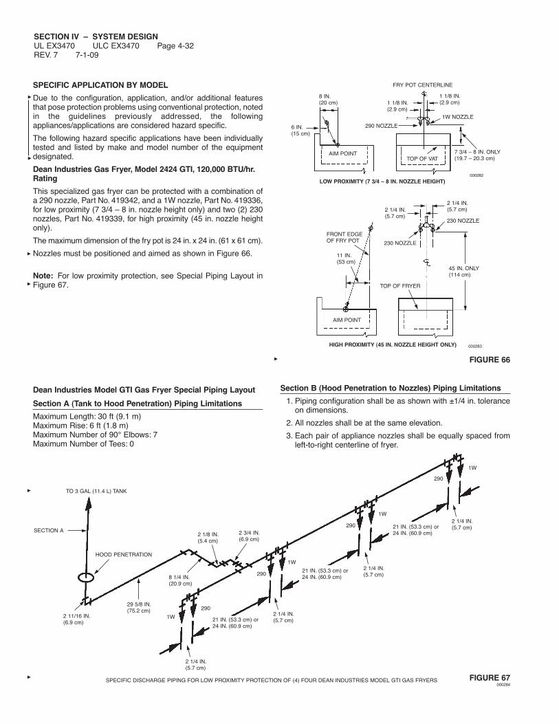
SECTION IV – SYSTEM DESIGNUL EX3470 ULC EX3470 Page 4-32REV. 7 7-1-09
SPECIFIC APPLICATION BY MODEL
Due to the configuration, application, and/or additional featuresthat pose protection problems using conventional protection, notedin the guidelines previously addressed, the followingappliances/applications are considered hazard specific.
The following hazard specific applications have been individuallytested and listed by make and model number of the equipmentdesignated.
Dean Industries Gas Fryer, Model 2424 GTI, 120,000 BTU/hr.Rating
This specialized gas fryer can be protected with a combination ofa 290 nozzle, Part No. 419342, and a 1W nozzle, Part No. 419336,for low proximity (7 3/4 – 8 in. nozzle height only) and two (2) 230nozzles, Part No. 419339, for high proximity (45 in. nozzle heightonly).
The maximum dimension of the fry pot is 24 in. x 24 in. (61 x 61 cm).
Nozzles must be positioned and aimed as shown in Figure 66.
Note: For low proximity protection, see Special Piping Layout inFigure 67.
Dean Industries Model GTI Gas Fryer Special Piping Layout
Section A (Tank to Hood Penetration) Piping Limitations
Maximum Length: 30 ft (9.1 m)Maximum Rise: 6 ft (1.8 m)Maximum Number of 90° Elbows: 7Maximum Number of Tees: 0
FIGURE 66
Section B (Hood Penetration to Nozzles) Piping Limitations
1. Piping configuration shall be as shown with ±1/4 in. toleranceon dimensions.
2. All nozzles shall be at the same elevation.
3. Each pair of appliance nozzles shall be equally spaced fromleft-to-right centerline of fryer.
FIGURE 67000284
HIGH PROXIMITY (45 IN. NOZZLE HEIGHT ONLY)
45 IN. ONLY(114 cm)
2 1/4 IN.(5.7 cm)
2 1/4 IN.(5.7 cm)
11 IN.(53 cm)
TOP OF FRYER
AIM POINT
FRONT EDGEOF FRY POT 230 NOZZLE
230 NOZZLE
000283
1W
290
2 1/4 IN.(5.7 cm)21 IN. (53.3 cm) or
24 IN. (60.9 cm)
2 1/4 IN.(5.7 cm)
21 IN. (53.3 cm) or24 IN. (60.9 cm)
2 1/4 IN.(5.7 cm)21 IN. (53.3 cm) or
24 IN. (60.9 cm)
2 1/4 IN.(5.7 cm)
290
1W
290
1W
290
1W
2 3/4 IN.(6.9 cm)
2 1/8 IN.(5.4 cm)
8 1/4 IN.(20.9 cm)
29 5/8 IN.(75.2 cm)
2 11/16 IN.(6.9 cm)
HOOD PENETRATION
TO 3 GAL (11.4 L) TANK
SECTION A
LOW PROXIMITY (7 3/4 – 8 IN. NOZZLE HEIGHT)
1 1/8 IN.(2.9 cm)
7 3/4 – 8 IN. ONLY(19.7 – 20.3 cm)
1 1/8 IN.(2.9 cm)
FRY POT CENTERLINE
TOP OF VATAIM POINT
1W NOZZLE
290 NOZZLE
000282
8 IN.(20 cm)
6 IN.(15 cm)
SPECIFIC DISCHARGE PIPING FOR LOW PROXIMITY PROTECTION OF (4) FOUR DEAN INDUSTRIES MODEL GTI GAS FRYERS
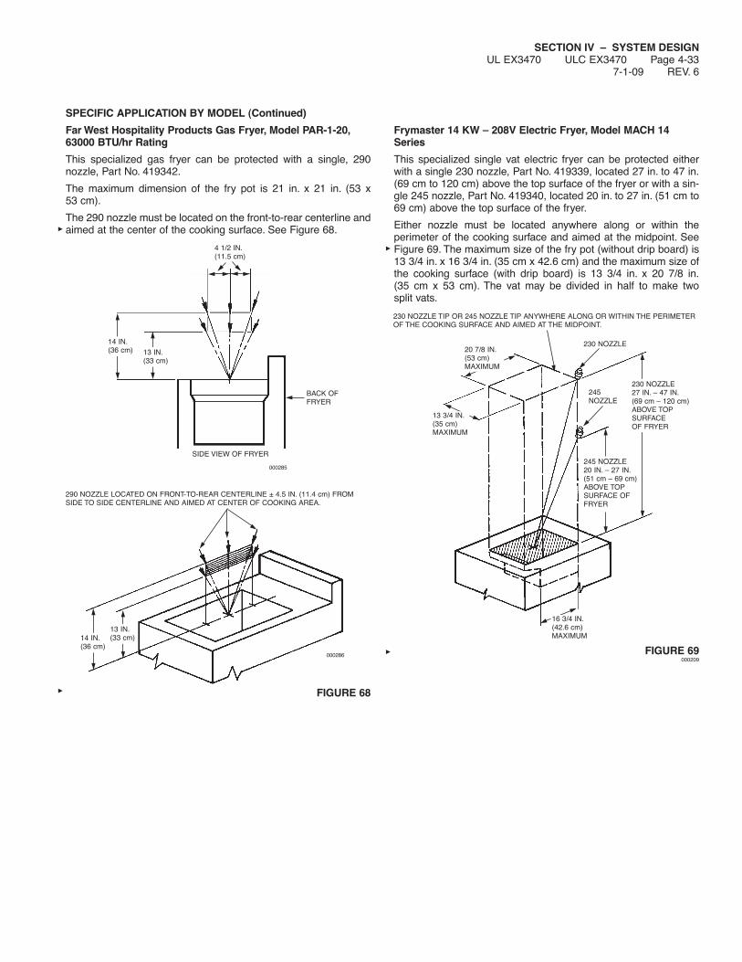
SECTION IV – SYSTEM DESIGNUL EX3470 ULC EX3470 Page 4-33
7-1-09 REV. 6
SPECIFIC APPLICATION BY MODEL (Continued)
Far West Hospitality Products Gas Fryer, Model PAR-1-20,63000 BTU/hr Rating
This specialized gas fryer can be protected with a single, 290nozzle, Part No. 419342.
The maximum dimension of the fry pot is 21 in. x 21 in. (53 x53 cm).
The 290 nozzle must be located on the front-to-rear centerline andaimed at the center of the cooking surface. See Figure 68.
FIGURE 68
Frymaster 14 KW – 208V Electric Fryer, Model MACH 14Series
This specialized single vat electric fryer can be protected eitherwith a single 230 nozzle, Part No. 419339, located 27 in. to 47 in.(69 cm to 120 cm) above the top surface of the fryer or with a sin-gle 245 nozzle, Part No. 419340, located 20 in. to 27 in. (51 cm to69 cm) above the top surface of the fryer.
Either nozzle must be located anywhere along or within theperimeter of the cooking surface and aimed at the midpoint. SeeFigure 69. The maximum size of the fry pot (without drip board) is13 3/4 in. x 16 3/4 in. (35 cm x 42.6 cm) and the maximum size ofthe cooking surface (with drip board) is 13 3/4 in. x 20 7/8 in.(35 cm x 53 cm). The vat may be divided in half to make twosplit vats.
FIGURE 69000209
290 NOZZLE LOCATED ON FRONT-TO-REAR CENTERLINE ± 4.5 IN. (11.4 cm) FROMSIDE TO SIDE CENTERLINE AND AIMED AT CENTER OF COOKING AREA.
000285
4 1/2 IN.(11.5 cm)
14 IN.(36 cm) 13 IN.
(33 cm)
BACK OFFRYER
SIDE VIEW OF FRYER
14 IN.(36 cm)
13 IN.(33 cm)
000286
230 NOZZLE TIP OR 245 NOZZLE TIP ANYWHERE ALONG OR WITHIN THE PERIMETEROF THE COOKING SURFACE AND AIMED AT THE MIDPOINT.
20 7/8 IN.(53 cm)MAXIMUM
13 3/4 IN.(35 cm)MAXIMUM
230 NOZZLE
230 NOZZLE27 IN. – 47 IN.(69 cm – 120 cm)ABOVE TOPSURFACEOF FRYER
245 NOZZLE20 IN. – 27 IN.(51 cm – 69 cm)ABOVE TOPSURFACE OFFRYER
16 3/4 IN.(42.6 cm)MAXIMUM
245NOZZLE

SECTION IV – SYSTEM DESIGNUL EX3470 ULC EX3470 Page 4-34REV. 8 7-1-09
SPECIFIC APPLICATION BY MODEL (Continued)
McDonald Fryer (Nozzle Heights of Less Than 20 In.)
When the 245 nozzle is used to protect McDonald’s fryers atheights less than 20 in. (51 cm) above the top of the fryer, the fol-lowing appliance and distribution piping rules shall apply:
1. Each McDonald’s gas or electric fryer shall be protected byone 245 nozzle, Part No. 419340. The fryer vat dimensions forone full vat or two split vats shall not exceed 14 in. x 15 in.(36 cm x 38 cm) without the dripboard and 14 in. x 21 in.(36 cm x 53 cm) with the dripboard.The heat input rating of the fryer shall not exceed 122,000BTU/HR.The 245 nozzle shall be located 18 in. to 20 in. (46 cm to51 cm) above the top of the fryer vat, 2 in. to 2 1/4 in. (5 cm to5.7 cm) to the right or left of the front-to-rear vat centerline,and 0 to 3 1/4 in. (0 cm to 8 cm) forward of the right-to-left vatcenterline, and aimed at the vat center point. See Figure 70.
FIGURE 70002297
2. The distance between the start of the first branch line and thestart of the last branch line shall not exceed 79 in. (201 cm).
3. The total length of all branch lines shall not exceed 162 in.(412 cm).
4. The 3 gallon agent tank shall be elevated above the connec-tions between the supply and branch lines.
5. The requirements of the following table shall not be exceeded:
Duct Plenum ApplianceSupply Branch Branch Branch
Requirement Line Line Line Line___________ ____ ____ ____ ____
Pipe Size 3/8 in. 3/8 in. 3/8 in. 3/8 in.
Maximum Length 140 in. 67 in. 6 in. 42 in.(356 cm) (170 cm) (15 cm) (107 cm)
Minimum Length 81 in. 4 in. 4 in. 17 in.(206 cm) (10 cm) (10 cm) (43 cm)
Maximum 5 3 1 690° Elbows
Maximum Tees 0 1 1 1
Maximum Flow 11 2 1 2Numbers
Minimum Flow 5 0 0 1/2Numbers
FRONT-TO-REARVAT CENTERLINE
REAR
AIMPOINT
NOZZLELOCATIONZONES
3 1/4IN.
2 IN. 2 IN.2 1/4 IN. 2 1/4 IN.
FRONT
RIGHT-TO-LEFT VATCENTERLINE
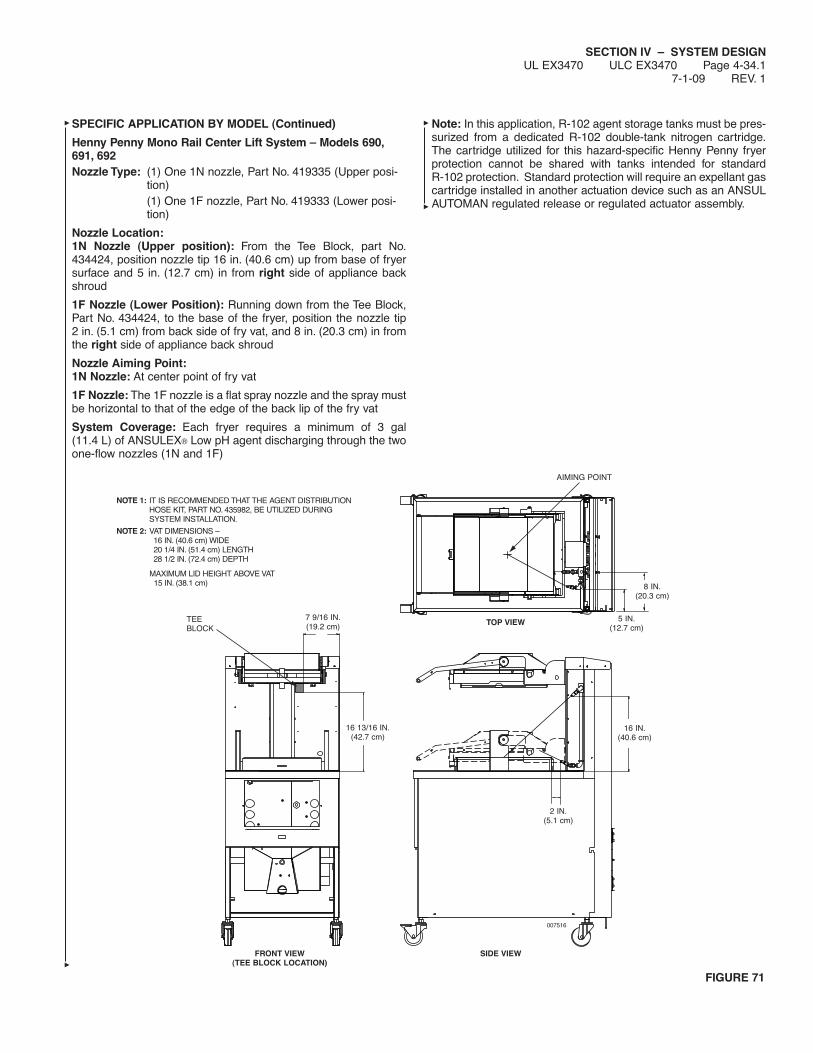
SECTION IV – SYSTEM DESIGNUL EX3470 ULC EX3470 Page 4-34.1
7-1-09 REV. 1
SPECIFIC APPLICATION BY MODEL (Continued)
Henny Penny Mono Rail Center Lift System – Models 690,691, 692Nozzle Type: (1) One 1N nozzle, Part No. 419335 (Upper posi-
tion)(1) One 1F nozzle, Part No. 419333 (Lower posi-tion)
Nozzle Location:1N Nozzle (Upper position): From the Tee Block, part No.434424, position nozzle tip 16 in. (40.6 cm) up from base of fryersurface and 5 in. (12.7 cm) in from right side of appliance backshroud
1F Nozzle (Lower Position): Running down from the Tee Block,Part No. 434424, to the base of the fryer, position the nozzle tip2 in. (5.1 cm) from back side of fry vat, and 8 in. (20.3 cm) in fromthe right side of appliance back shroud
Nozzle Aiming Point:1N Nozzle: At center point of fry vat
1F Nozzle: The 1F nozzle is a flat spray nozzle and the spray mustbe horizontal to that of the edge of the back lip of the fry vat
System Coverage: Each fryer requires a minimum of 3 gal(11.4 L) of ANSULEX® Low pH agent discharging through the twoone-flow nozzles (1N and 1F)
Note: In this application, R-102 agent storage tanks must be pres-surized from a dedicated R-102 double-tank nitrogen cartridge.The cartridge utilized for this hazard-specific Henny Penny fryerprotection cannot be shared with tanks intended for standardR-102 protection. Standard protection will require an expellant gascartridge installed in another actuation device such as an ANSULAUTOMAN regulated release or regulated actuator assembly.
007516
16 IN.(40.6 cm)
16 13/16 IN.(42.7 cm)
8 IN.(20.3 cm)
2 IN.(5.1 cm)
5 IN.(12.7 cm)
7 9/16 IN.(19.2 cm)
SIDE VIEW
FIGURE 71
TOP VIEW
FRONT VIEW(TEE BLOCK LOCATION)
AIMING POINT
TEEBLOCK
NOTE 1: IT IS RECOMMENDED THAT THE AGENT DISTRIBUTIONHOSE KIT, PART NO. 435982, BE UTILIZED DURINGSYSTEM INSTALLATION.
NOTE 2: VAT DIMENSIONS –16 IN. (40.6 cm) WIDE20 1/4 IN. (51.4 cm) LENGTH28 1/2 IN. (72.4 cm) DEPTH
MAXIMUM LID HEIGHT ABOVE VAT15 IN. (38.1 cm)

SECTION IV – SYSTEM DESIGNUL EX3470 ULC EX3470 Page 4-34.2REV. 1 7-1-09
SPECIFIC APPLICATION BY MODEL (Continued)
Henny Penny Dual Lift System – Models 580, 581, 582, 590,591, 592, 680, 682
Nozzle Type:1N Nozzle (Upper position): From the Tee Block, part No.434424, position nozzle tip 16 in. (40.6 cm) up from base of fryersurface and 5 in. (12.7 cm) in from left side of appliance backshroud
1F Nozzle (Lower position): Running down from the Tee Block,Part No. 434424, to the base of the fryer, position the nozzle tip2 in. (5.1 cm) from back side of fry vat, and 8 in. (20.3 cm) in fromthe left side of appliance back shroud
Nozzle Aiming Point:1N Nozzle: At center point of fry vat
1F Nozzle: The 1F nozzle is a flat spray nozzle and the spray mustbe horizontal to that of the edge of the back lip of the fry vat
System Coverage: Each fryer requires a minimum of 3 gal(11.4 L) of ANSULEX Low pH agent discharging through the twoone-flow nozzles (1N and 1F)
Note: In this application, R-102 agent storage tanks must be pres-surized from a dedicated R-102 double-tank nitrogen cartridge.The cartridge utilized for this hazard-specific Henny Penny fryerprotection cannot be shared with tanks intended for standardR-102 protection. Standard protection will require an expellant gascartridge installed in another actuation device such as an ANSULAUTOMAN regulated release or regulated actuator assembly.
007515
16 IN.(40.6 cm)
16 13/16 IN.(42.7 cm)
8 IN.(20.3 cm)
2 IN.(5.1 cm)
5 IN.(12.7 cm)
7 9/16 IN.(19.2 cm)
SIDE VIEW
FIGURE 72
TOP VIEW
FRONT VIEW(TEE BLOCK LOCATION)
AIMING POINT
TEEBLOCK
NOTE 1: IT IS RECOMMENDED THAT THE AGENT DISTRIBUTIONHOSE KIT, PART NO. 435982, BE UTILIZED DURING SYSTEMINSTALLATION.
NOTE 2: VAT DIMENSIONS –16 IN. (40.6 cm) WIDE20 1/4 IN. (51.4 cm) LENGTH28 1/2 IN. (72.4 cm) DEPTH
MAXIMUM LID HEIGHT ABOVE VAT15 IN. (38.1 cm)
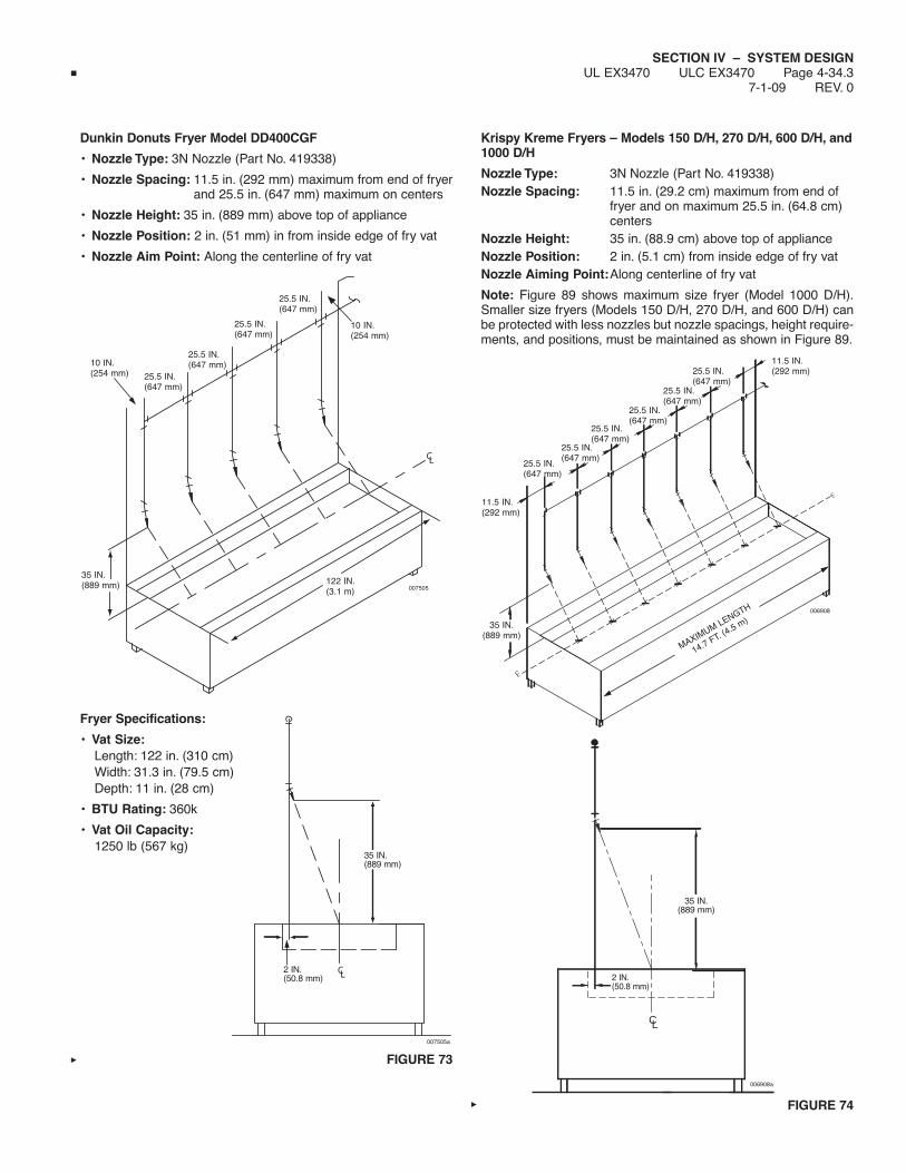
SECTION IV – SYSTEM DESIGNUL EX3470 ULC EX3470 Page 4-34.3
7-1-09 REV. 0
Dunkin Donuts Fryer Model DD400CGF
• Nozzle Type: 3N Nozzle (Part No. 419338)
• Nozzle Spacing: 11.5 in. (292 mm) maximum from end of fryerand 25.5 in. (647 mm) maximum on centers
• Nozzle Height: 35 in. (889 mm) above top of appliance
• Nozzle Position: 2 in. (51 mm) in from inside edge of fry vat
• Nozzle Aim Point: Along the centerline of fry vat
Fryer Specifications:
• Vat Size:Length: 122 in. (310 cm)Width: 31.3 in. (79.5 cm)Depth: 11 in. (28 cm)
• BTU Rating: 360k
• Vat Oil Capacity:1250 lb (567 kg)
FIGURE 73
Krispy Kreme Fryers – Models 150 D/H, 270 D/H, 600 D/H, and1000 D/H
Nozzle Type: 3N Nozzle (Part No. 419338)Nozzle Spacing: 11.5 in. (29.2 cm) maximum from end of
fryer and on maximum 25.5 in. (64.8 cm)centers
Nozzle Height: 35 in. (88.9 cm) above top of applianceNozzle Position: 2 in. (5.1 cm) from inside edge of fry vatNozzle Aiming Point:Along centerline of fry vat
Note: Figure 89 shows maximum size fryer (Model 1000 D/H).Smaller size fryers (Models 150 D/H, 270 D/H, and 600 D/H) canbe protected with less nozzles but nozzle spacings, height require-ments, and positions, must be maintained as shown in Figure 89.
FIGURE 74
10 IN.(254 mm)
35 IN.(889 mm)
10 IN.(254 mm)
25.5 IN.(647 mm)
25.5 IN.(647 mm)
25.5 IN.(647 mm)
25.5 IN.(647 mm)
007505
007505a
2 IN.(50.8 mm)
35 IN.(889 mm)
122 IN.(3.1 m)
CL
LC
CL
35"35"
11.5 IN.(292 mm)
35 IN.(889 mm)
11.5 IN.(292 mm)
25.5 IN.(647 mm)
25.5 IN.(647 mm)
25.5 IN.(647 mm)
25.5 IN.(647 mm)
25.5 IN.(647 mm)
25.5 IN.(647 mm)
006908
006908a
2 IN.(50.8 mm)
35 IN.(889 mm)
MAXIMUM LENGTH
14.7 FT. (4.5 m)

SECTION IV – SYSTEM DESIGNUL EX3470 ULC EX3470 Page 4-34.4REV. 0 7-1-09
NOTES:

SECTION IV – SYSTEM DESIGNUL EX3470 ULC EX3470 Page 4-35
7-1-09 REV. 6
DUKE Chain Broiler – Model FBB – Low Proximity
.
DUKE Chain Broiler With or Without Catalyst View
Exhaust Deflector Size – 6.25 in. (15.9 cm) x 26.75 in.(67.9 cm):
• Nozzle Quantity/Type: (2) Two 245 nozzles, Part No. 419340.
• Nozzle Height: 8 in. to 15 in. (20.3 cm to 38.1 cm) above topof appliance.
• Nozzle Location: 6.5 in. (16.5 cm) from front or back edge ofhazardFirst nozzle positioned 17.25 in. (43.8 cm)from right side of broiler (facing broiler)Second nozzle positioned 15 in. (38.1 cm)from first nozzleNozzle must be oriented to spray ontoimpedance plate.
• Nozzle Aiming Point: Aimed at at center of impedance plate
Note: If the deflector or flue gas diverter is rotated 180 degrees,the nozzles must also rotate to discharge into the opening.
SPECIFIC APPLICATION BY MODEL (Continued)
DUKE Chain Broiler – Model FBB-High Proximity
DUKE Chain Broiler With or Without Catalyst View:
• Nozzle Quantity/Type: (1) One 2W nozzle, Part No. 419337
• Nozzle Height: 20 in. (508 mm) above top of appliance
• Nozzle Location: Centered 6 1/2 in. (165 mm) back from frontfeed edge of appliance. Nozzle must be oriented to spray ontoimpedance plate.
• Nozzle Aiming Point: Aimed at center of impedance plate
Side View Front View (Feed Side)
6 1/2 in.(165 mm)
2W Nozzle
20 in. (508 mm)
2W Nozzle
FIGURE 75
FIGURE 76
IMPEDANCEPLATE
LOW SIDEOF PLATE
007414
6 1/2 IN. (165 mm) FROM EDGE OF APPLIANCETHAT DEFLECTOR PLATE IS
ANGLED TOWARD (SEE SIDE VIEW)
6 1/2 IN. (165 mm) FROM EDGE OFAPPLIANCE THAT
DEFLECTOR PLATEIS ANGLEDTOWARD
8 IN. (203 mm) to15 IN. (381 mm)
NOZZLE HEIGHTPRODUCTOUTPUT
PRODUCTOUTPUT
FLUE GASDIVERTER
BACK FRONT
245 NOZZLE
PERFORATEDGRILL
CENTERDUCT
PRODUCTINPUT
15 IN.(381 mm)
17 1/4 IN.(438.15 mm)
TOP VIEW SIDE VIEW008100 008099
PRODUCTINPUT
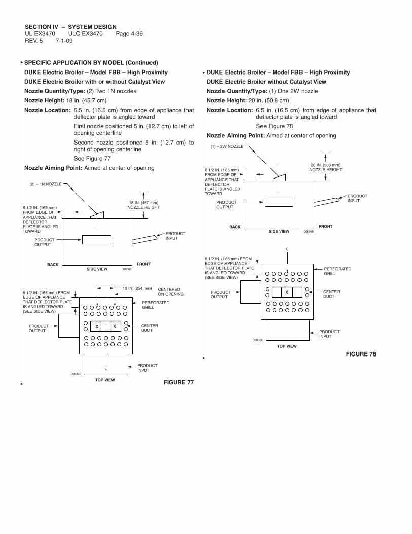
SECTION IV – SYSTEM DESIGNUL EX3470 ULC EX3470 Page 4-36REV. 5 7-1-09
SPECIFIC APPLICATION BY MODEL (Continued)
DUKE Electric Broiler – Model FBB – High Proximity
DUKE Electric Broiler with or without Catalyst View
Nozzle Quantity/Type: (2) Two 1N nozzles
Nozzle Height: 18 in. (45.7 cm)
Nozzle Location: 6.5 in. (16.5 cm) from edge of appliance thatdeflector plate is angled toward
First nozzle positioned 5 in. (12.7 cm) to left ofopening centerline
Second nozzle positioned 5 in. (12.7 cm) toright of opening centerline
See Figure 77
Nozzle Aiming Point: Aimed at center of opening
FIGURE 77
DUKE Electric Broiler – Model FBB – High Proximity
DUKE Electric Broiler without Catalyst View
Nozzle Quantity/Type: (1) One 2W nozzle
Nozzle Height: 20 in. (50.8 cm)
Nozzle Location: 6.5 in. (16.5 cm) from edge of appliance thatdeflector plate is angled toward
See Figure 78
Nozzle Aiming Point: Aimed at center of opening
FIGURE 78
008365
PRODUCTINPUTPRODUCT
OUTPUT
FRONTBACKSIDE VIEW
(2) – 1N NOZZLE
6 1/2 IN. (165 mm)FROM EDGE OFAPPLIANCE THATDEFLECTORPLATE IS ANGLEDTOWARD
18 IN. (457 mm)NOZZLE HEIGHT
PRODUCTINPUT
PERFORATEDGRILL
CENTERDUCT
PRODUCTOUTPUT
CENTEREDON OPENING
TOP VIEW
6 1/2 IN. (165 mm) FROMEDGE OF APPLIANCETHAT DEFLECTOR PLATEIS ANGLED TOWARD(SEE SIDE VIEW)
008366
10 IN. (254 mm)
PRODUCTINPUT
PERFORATEDGRILL
CENTERDUCT
PRODUCTOUTPUT
TOP VIEW
6 1/2 IN. (165 mm) FROMEDGE OF APPLIANCETHAT DEFLECTOR PLATEIS ANGLED TOWARD(SEE SIDE VIEW)
008366
008365
PRODUCTINPUTPRODUCT
OUTPUT
FRONTBACKSIDE VIEW
(1) – 2W NOZZLE
6 1/2 IN. (165 mm)FROM EDGE OFAPPLIANCE THATDEFLECTORPLATE IS ANGLEDTOWARD
20 IN. (508 mm)NOZZLE HEIGHT

SECTION IV – SYSTEM DESIGNUL EX3470 ULC EX3470 Page 4-37
7-1-09 REV. 5
SPECIFIC APPLICATION BY MODEL (Continued)
DUKE Electric Broiler – Model FBB – Low Proximity
DUKE Electric Broiler with or without Catalyst View
Nozzle Quantity/Type: (2) Two 245 nozzles
Nozzle Height: 8 in. (20.3 cm) to 15 in. (38.1 cm)
Nozzle Location: 6.5 in. (16.5 cm) from edge of appliance thatdeflector plate is angled toward
First nozzle positioned 17.5 in. (44.5 cm) fromright side of broiler (facing broiler)
Second nozzle positioned 15 in. (38.1 cm) fromfirst nozzle
See Figure 79
Nozzle Aiming Point: Aimed at center of opening
FIGURE 79
SPECIFIC APPLICATION BY MODEL (Continued)
Nieco Broiler Model 940, 962 or 960 With Catalytic ConverterProtection
Note: Nieco broilers without catalytic converters use standardchain broiler protection options.
Certain models of the Nieco broiler (Models 940, 962, and 960)are equipped with a catalytic converter to comply with new cleanair laws. Because of the converter, it is necessary to protect thesebroilers in a special way. The guidelines for protecting these broil-ers are as follows:
– The maximum internal broiling area is 29 in. x 23.5 in. (74 cmx 60 cm).
– An R-102 3-gallon system with a maximum of 6 flow numbers,must be used for protection of each broiler, including plenumand duct.
– Each individual broiler must be protected with a minimum of (2)two, 1N nozzles, Part No. 419335. The nozzles must be locat-ed as shown in Figure 80.
– The broiler must be fitted with two 1 in. (2.5 cm) high agent bar-riers on the angled surface of the broiler. If these have not beencompleted by the equipment supplier, they must be added inthe field.
FIGURE 80
000250
(2) 1N NOZZLESPART NO. 56930
12 IN. TO 13 IN.(31 cm TO 33 cm)
30°
14.25 ± 1 IN.(36 cm)
LOCATE NOZZLES 2 13/16 IN. (7.1 cm) ONEACH SIDE OF BROILER CENTER LINE
14.25 ± 1 IN.(36 cm)
000774
008365
PRODUCTINPUTPRODUCT
OUTPUT
FRONTBACKSIDE VIEW
(2) – 245 NOZZLE
6 1/2 IN. (165 mm)FROM EDGE OFAPPLIANCE THATDEFLECTORPLATE IS ANGLEDTOWARD
8 IN. (203 mm) TO15 IN. (381 mm)
NOZZLE HEIGHT
PRODUCTINPUT
PERFORATEDGRILL
CENTERDUCT
PRODUCTOUTPUT
TOP VIEW
6 1/2 IN. (165 mm) FROMEDGE OF APPLIANCETHAT DEFLECTOR PLATEIS ANGLED TOWARD(SEE SIDE VIEW)
008368
15 IN.(381 mm)
17 1/2 IN.(444.5 mm)
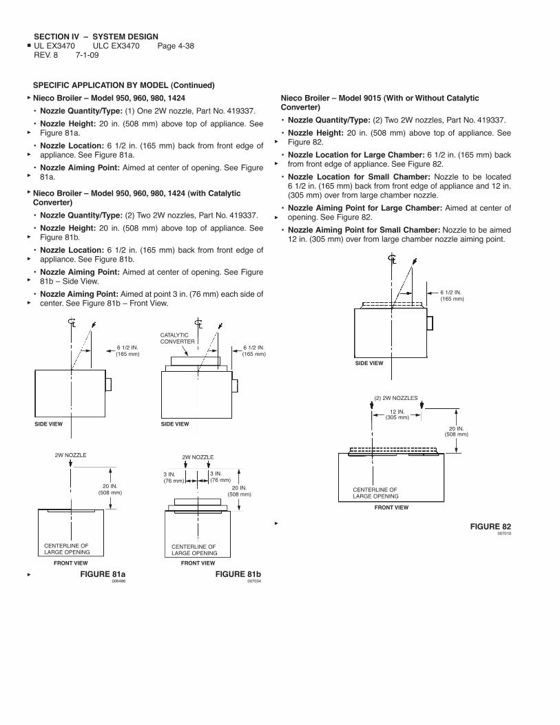
SECTION IV – SYSTEM DESIGNUL EX3470 ULC EX3470 Page 4-38REV. 8 7-1-09
SPECIFIC APPLICATION BY MODEL (Continued)
Nieco Broiler – Model 950, 960, 980, 1424
• Nozzle Quantity/Type: (1) One 2W nozzle, Part No. 419337.
• Nozzle Height: 20 in. (508 mm) above top of appliance. SeeFigure 81a.
• Nozzle Location: 6 1/2 in. (165 mm) back from front edge ofappliance. See Figure 81a.
• Nozzle Aiming Point: Aimed at center of opening. See Figure81a.
Nieco Broiler – Model 950, 960, 980, 1424 (with CatalyticConverter)
• Nozzle Quantity/Type: (2) Two 2W nozzles, Part No. 419337.
• Nozzle Height: 20 in. (508 mm) above top of appliance. SeeFigure 81b.
• Nozzle Location: 6 1/2 in. (165 mm) back from front edge ofappliance. See Figure 81b.
• Nozzle Aiming Point: Aimed at center of opening. See Figure81b – Side View.
• Nozzle Aiming Point: Aimed at point 3 in. (76 mm) each side ofcenter. See Figure 81b – Front View.
Nieco Broiler – Model 9015 (With or Without CatalyticConverter)
• Nozzle Quantity/Type: (2) Two 2W nozzles, Part No. 419337.
• Nozzle Height: 20 in. (508 mm) above top of appliance. SeeFigure 82.
• Nozzle Location for Large Chamber: 6 1/2 in. (165 mm) backfrom front edge of appliance. See Figure 82.
• Nozzle Location for Small Chamber: Nozzle to be located6 1/2 in. (165 mm) back from front edge of appliance and 12 in.(305 mm) over from large chamber nozzle.
• Nozzle Aiming Point for Large Chamber: Aimed at center ofopening. See Figure 82.
• Nozzle Aiming Point for Small Chamber: Nozzle to be aimed12 in. (305 mm) over from large chamber nozzle aiming point.
FIGURE 82007010
6 1/2 IN.(165 mm)
SIDE VIEW
2W NOZZLE
CENTERLINE OFLARGE OPENING
FIGURE 81a006486
FIGURE 81b007034
FRONT VIEW
20 IN.(508 mm)
6 1/2 IN.(165 mm)
SIDE VIEW
2W NOZZLE
CENTERLINE OFLARGE OPENING
FRONT VIEW
20 IN.(508 mm)
3 IN.(76 mm)
3 IN.(76 mm)
CATALYTICCONVERTER
6 1/2 IN.(165 mm)
SIDE VIEW
FRONT VIEW
(2) 2W NOZZLES
20 IN.(508 mm)
CENTERLINE OFLARGE OPENING
12 IN.(305 mm)
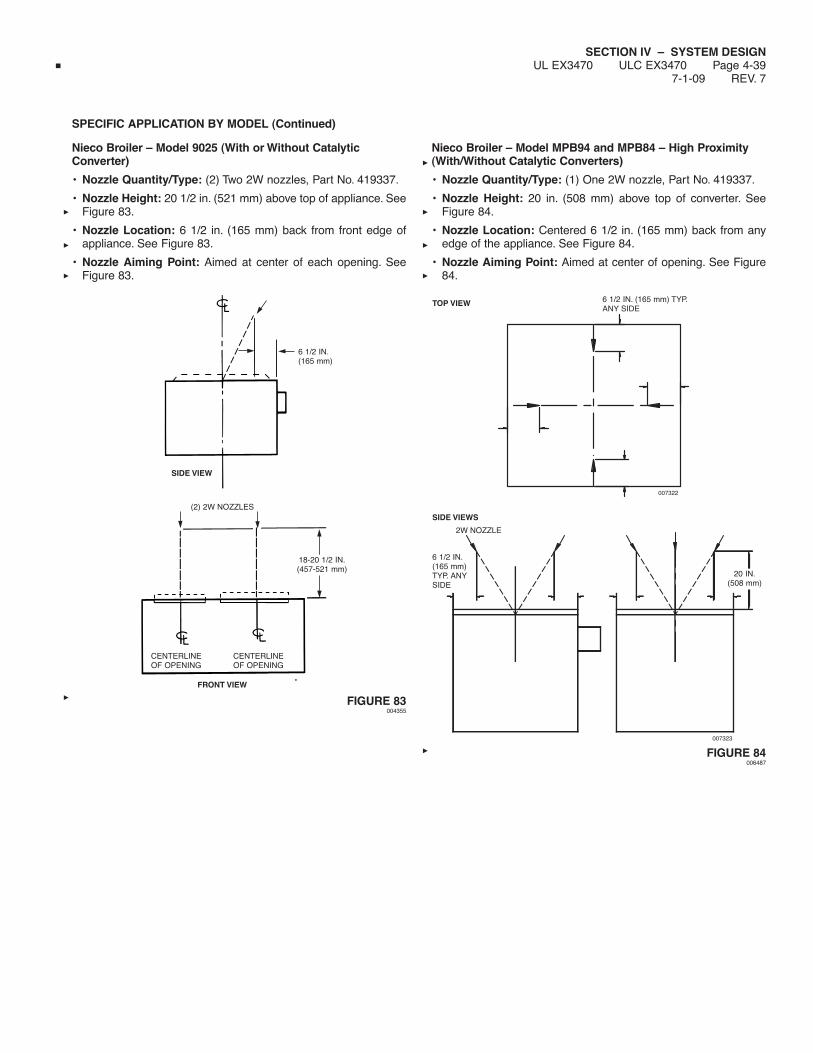
SECTION IV – SYSTEM DESIGNUL EX3470 ULC EX3470 Page 4-39
7-1-09 REV. 7
SPECIFIC APPLICATION BY MODEL (Continued)
Nieco Broiler – Model 9025 (With or Without CatalyticConverter)
• Nozzle Quantity/Type: (2) Two 2W nozzles, Part No. 419337.
• Nozzle Height: 20 1/2 in. (521 mm) above top of appliance. SeeFigure 83.
• Nozzle Location: 6 1/2 in. (165 mm) back from front edge ofappliance. See Figure 83.
• Nozzle Aiming Point: Aimed at center of each opening. SeeFigure 83.
FIGURE 83004355
Nieco Broiler – Model MPB94 and MPB84 – High Proximity(With/Without Catalytic Converters)
• Nozzle Quantity/Type: (1) One 2W nozzle, Part No. 419337.
• Nozzle Height: 20 in. (508 mm) above top of converter. SeeFigure 84.
• Nozzle Location: Centered 6 1/2 in. (165 mm) back from anyedge of the appliance. See Figure 84.
• Nozzle Aiming Point: Aimed at center of opening. See Figure84.
FIGURE 84006487
SIDE VIEW
SIDE VIEWS
TOP VIEW
FRONT VIEW
18-20 1/2 IN.(457-521 mm)
CENTERLINEOF OPENING
CENTERLINEOF OPENING
(2) 2W NOZZLES
6 1/2 IN.(165 mm)
20 IN.(508 mm)
2W NOZZLE
6 1/2 IN.(165 mm)TYP. ANYSIDE
6 1/2 IN. (165 mm) TYP.ANY SIDE
007322
007323
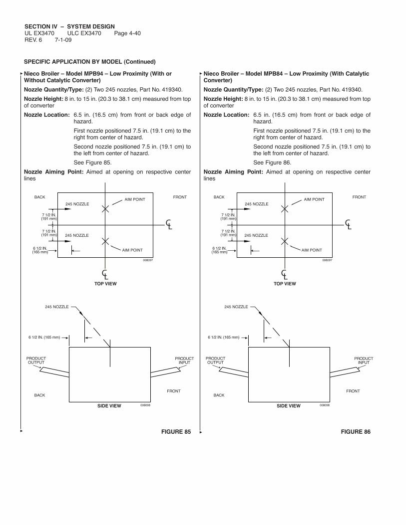
SECTION IV – SYSTEM DESIGNUL EX3470 ULC EX3470 Page 4-40REV. 6 7-1-09
SPECIFIC APPLICATION BY MODEL (Continued)
Nieco Broiler – Model MPB94 – Low Proximity (With orWithout Catalytic Converter)
Nozzle Quantity/Type: (2) Two 245 nozzles, Part No. 419340.
Nozzle Height: 8 in. to 15 in. (20.3 to 38.1 cm) measured from topof converter
Nozzle Location: 6.5 in. (16.5 cm) from front or back edge ofhazard.
First nozzle positioned 7.5 in. (19.1 cm) to theright from center of hazard.
Second nozzle positioned 7.5 in. (19.1 cm) tothe left from center of hazard.
See Figure 85.
Nozzle Aiming Point: Aimed at opening on respective centerlines
FIGURE 85
Nieco Broiler – Model MPB84 – Low Proximity (With CatalyticConverter)
Nozzle Quantity/Type: (2) Two 245 nozzles, Part No. 419340.
Nozzle Height: 8 in. to 15 in. (20.3 to 38.1 cm) measured from topof converter
Nozzle Location: 6.5 in. (16.5 cm) from front or back edge ofhazard.
First nozzle positioned 7.5 in. (19.1 cm) to theright from center of hazard.
Second nozzle positioned 7.5 in. (19.1 cm) tothe left from center of hazard.
See Figure 86.
Nozzle Aiming Point: Aimed at opening on respective centerlines
FIGURE 86
CL
CL
FRONTAIM POINT
245 NOZZLE
245 NOZZLE
AIM POINT
TOP VIEW
008097
008098
7 1/2 IN.(191 mm)
7 1/2 IN.(191 mm)
6 1/2 IN.(165 mm)
BACK
FRONTBACK
245 NOZZLE
6 1/2 IN. (165 mm)
PRODUCTINPUT
PRODUCTOUTPUT
SIDE VIEW
CL
CL
FRONTAIM POINT
245 NOZZLE
245 NOZZLE
AIM POINT
TOP VIEW
008097
008098
7 1/2 IN.(191 mm)
7 1/2 IN.(191 mm)
6 1/2 IN.(165 mm)
BACK
FRONTBACK
245 NOZZLE
6 1/2 IN. (165 mm)
PRODUCTINPUT
PRODUCTOUTPUT
SIDE VIEW
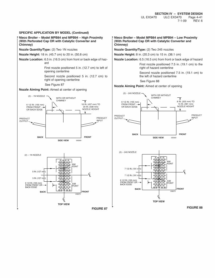
SECTION IV – SYSTEM DESIGNUL EX3470 ULC EX3470 Page 4-41
7-1-09 REV. 6
SPECIFIC APPLICATION BY MODEL (Continued)
Nieco Broiler – Model MPB84 and MPB94 – High Proximity(With Perforated Cap OR with Catalytic Converter andChimney)
Nozzle Quantity/Type: (2) Two 1N nozzles
Nozzle Height: 18 in. (45.7 cm) to 20 in. (50.8 cm)
Nozzle Location: 6.5 in. (16.5 cm) from front or back edge of haz-ard
First nozzle positioned 5 in. (12.7 cm) to left ofopening centerline
Second nozzle positioned 5 in. (12.7 cm) toright of opening centerline
See Figure 87
Nozzle Aiming Point: Aimed at center of opening
FIGURE 87
Nieco Broiler – Model MPB84 and MPB94 – Low Proximity(With Perforated Cap OR with Catalytic Converter andChimney)
Nozzle Quantity/Type: (2) Two 245 nozzles
Nozzle Height: 8 in. (20.3 cm) to 15 in. (38.1 cm)
Nozzle Location: 6.5 (16.5 cm) from front or back edge of hazard
First nozzle positioned 7.5 in. (19.1 cm) to theright of hazard centerline
Second nozzle positioned 7.5 in. (19.1 cm) tothe left of hazard centerline
See Figure 88
Nozzle Aiming Point: Aimed at center of opening
FIGURE 88
008370
6 1/2 IN. (165 mm)FROM FRONT ORBACK EDGE
5 IN. (127 mm)
5 IN. (127 mm)
(2) – 1N NOZZLE
AIMPOINT
AIMPOINT
TOP VIEW
008369
PRODUCTINPUT
PRODUCTOUTPUT
FRONT
FRONT
BACK
BACK
SIDE VIEW
(2) – 1N NOZZLE
6 1/2 IN. (165 mm)FROM FRONTOR BACK EDGE
WITH OR WITHOUTCHIMNEY
18 IN. (457 mm) TO20 IN. (508 mm)
NOZZLE HEIGHT
008370
6 1/2 IN. (165 mm)FROM FRONT ORBACK EDGE
7 1/2 IN. (191 mm)
7 1/2 IN. (191 mm)
(2) – 245 NOZZLE
AIMPOINT
AIMPOINT
TOP VIEW
008369
PRODUCTINPUT
PRODUCTOUTPUT
FRONT
FRONT
BACK
BACK
SIDE VIEW
(2) – 245 NOZZLE
6 1/2 IN. (165 mm)FROM FRONTOR BACK EDGE
WITH OR WITHOUTCHIMNEY
8 IN. (203 mm) TO15 IN. (381 mm)
NOZZLE HEIGHT
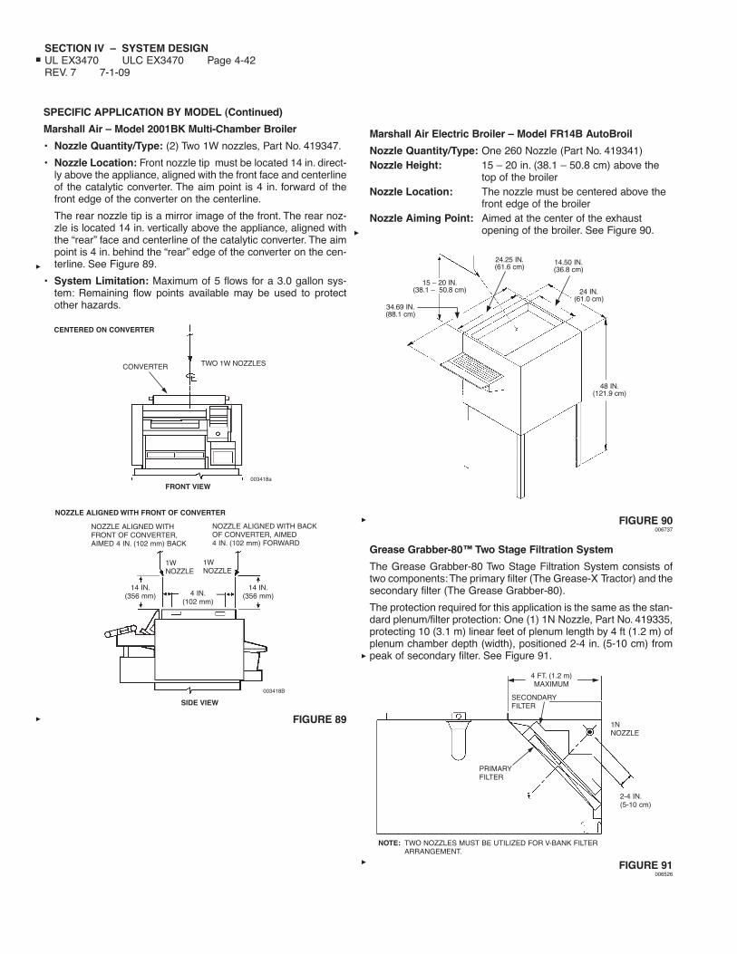
SECTION IV – SYSTEM DESIGNUL EX3470 ULC EX3470 Page 4-42REV. 7 7-1-09
SPECIFIC APPLICATION BY MODEL (Continued)
Marshall Air – Model 2001BK Multi-Chamber Broiler
• Nozzle Quantity/Type: (2) Two 1W nozzles, Part No. 419347.
• Nozzle Location: Front nozzle tip must be located 14 in. direct-ly above the appliance, aligned with the front face and centerlineof the catalytic converter. The aim point is 4 in. forward of thefront edge of the converter on the centerline.
The rear nozzle tip is a mirror image of the front. The rear noz-zle is located 14 in. vertically above the appliance, aligned withthe “rear” face and centerline of the catalytic converter. The aimpoint is 4 in. behind the “rear” edge of the converter on the cen-terline. See Figure 89.
• System Limitation: Maximum of 5 flows for a 3.0 gallon sys-tem: Remaining flow points available may be used to protectother hazards.
FIGURE 89
Marshall Air Electric Broiler – Model FR14B AutoBroil
Nozzle Quantity/Type: One 260 Nozzle (Part No. 419341)Nozzle Height: 15 – 20 in. (38.1 – 50.8 cm) above the
top of the broilerNozzle Location: The nozzle must be centered above the
front edge of the broilerNozzle Aiming Point: Aimed at the center of the exhaust
opening of the broiler. See Figure 90.
FIGURE 90006737
Grease Grabber-80™ Two Stage Filtration System
The Grease Grabber-80 Two Stage Filtration System consists oftwo components:The primary filter (The Grease-X Tractor) and thesecondary filter (The Grease Grabber-80).
The protection required for this application is the same as the stan-dard plenum/filter protection: One (1) 1N Nozzle, Part No. 419335,protecting 10 (3.1 m) linear feet of plenum length by 4 ft (1.2 m) ofplenum chamber depth (width), positioned 2-4 in. (5-10 cm) frompeak of secondary filter. See Figure 91.
FIGURE 91006526
TWO 1W NOZZLES
003418a
CONVERTER
FRONT VIEW
CENTERED ON CONVERTER
NOZZLE ALIGNED WITHFRONT OF CONVERTER,AIMED 4 IN. (102 mm) BACK
NOZZLE ALIGNED WITH BACKOF CONVERTER, AIMED4 IN. (102 mm) FORWARD
1WNOZZLE
1WNOZZLE
4 IN.(102 mm)
003418B
SIDE VIEW
NOZZLE ALIGNED WITH FRONT OF CONVERTER
14 IN.(356 mm)
14 IN.(356 mm)
15 – 20 IN.(38.1 – 50.8 cm)
24.25 IN.(61.6 cm)
24 IN.(61.0 cm)
48 IN.(121.9 cm)
34.69 IN.(88.1 cm)
14.50 IN.(36.8 cm)
SECONDARYFILTER
NOTE: TWO NOZZLES MUST BE UTILIZED FOR V-BANK FILTERARRANGEMENT.
PRIMARYFILTER
1NNOZZLE
2-4 IN.(5-10 cm)
4 FT. (1.2 m)MAXIMUM

SECTION IV – SYSTEM DESIGNUL EX3470 ULC EX3470 Page 4-43
7-1-09 REV. 6
OVERLAPPING NOZZLE COVERAGE
Overlapping Coverage – Option 1
For each group of protected appliances under a common hood(s),the overlapping nozzles must be located from right to left so thateach end nozzle is located a maximum of 6 in. (15.2 cm) inside theoutside edge of the cooking hazard of each end appliance, and theinside overlapping nozzles must be located between the two endnozzles at a maximum spacing of 12 in. (30.5 cm).
Hazard Zone
The hazard zone is defined as a theoretical, flat and level, rectan-gular surface, that includes all of the cooking hazards of the pro-tected appliances under a common hood(s). The purpose of thehazard zone is to provide a means of locating the appliances andthe overlapping nozzles, as well as aiming the overlapping noz-zles. The hazard zone measures 28 in. (71.1 cm) deep by thelength of the cooking hazard(s). The centerline of the hazard zonemust bisect the 28 in. (71.1 cm) depth (from front to back) and runfrom right-to-left for the full width of the hazard zone.
Overlapping Nozzle Appliance Protection
Overlapping Nozzle Appliance Protection is defined as protectionof cooking appliances by nozzles spaced uniformly at uniform ele-vations under a common hood(s). Overlapping protection of appli-ances is continuous for the full length of the hood or divided whengroup(s) of protected appliances are separated by counters orappliances not requiring protection.
Full hood continuous protection is defined as overlapping noz-zle appliance protection that covers the appliance line-up locatedunder the total hood length. All appliances requiring protection arethe appliances under the hood that can be an ignition source ofgrease in the hood, grease removal device or the duct.
Group protection is defined as overlapping nozzle appliance pro-tection that protects individual hazard zones located under a com-mon hood. These “groups” of appliances may be separated byappliances not requiring protection, such as steam equipment orwork tables, or by dedicated appliance protection, such as sala-mander broilers.
See Figure 91d (full hood continuous protection) and Figure 91e(multiple group protection).
Dedicated Nozzle Appliance Protection
Appliance protection using dedicated nozzle coverage is definedas protection of cooking appliances with enclosed cooking haz-ards, such as upright broilers, which cannot be protected withoverlapping nozzles and therefore must be protected with nozzlesdedicated to the appliance.
General Design Limitations
• Maximum depth of zone is 28 in. (71.1 cm).
• The 245 nozzle, Part No. 419340, is the only approved nozzle foroverlapping (zone) protection.
• Nozzle must be located 0 in. to 6 in. (0 cm to 15.2 cm) forwardof zone centerline, aimed back at the zone centerline.
• Nozzles must be spaced a maximum of 6 in. (15.2 cm) fromeach end of hazard and then a maximum of 12 in. (30.5 cm) oncenter for the remaining overlapping nozzles until the completehazard is covered.
• For appliance hazard surfaces with listed protection exceed-ing the standard hazard zone of 28 in. (71.1 cm) in depth, thehazard surface(s) must be aligned with the back edge of thehazard zone, with the front edge overhanging the front edge ofthe zone. See Appliance Chart, Table 1.
• For appliance hazard surfaces that exceed the listed protec-tion sizes, multiple zones must be utilized. Align entire hazardsurface area within the multiple zones.
• All hood, duct, individual appliance, and piping limitations are asspecified in the R-102 Design, Installation, Recharge andMaintenance Manual, Part No. 418087.
• All appliance protection currently listed in the R-102 DesignManual, Part No. 418087, is also approved protection. Zone pro-tection can be considered optional protection.
TABLE 1Overlapping Nozzle Coverage (Zone Protection)
Appliance Type Maximum Cooking Hazard____________ ______________________
Fryer 34 in. (86.4 cm) Deep x 5.8 ft2(0.5 m2)
Griddle 30 in. (76.2 cm) Deep x Unlimited Length
Range 28 in. (71.1 cm) Deep x Unlimited Length
Wok, Maximum 30 in. (76.2 cm) Diameter x 8 in.(20.3 cm) Deep
Wok, Minimum 11 in. (27.9 cm) Diameter x 3 in.(7.6 cm) Deep
Braising Pan/Tilt 34 in. (86.4 cm) Deep x UnlimitedSkillet* Length
Lava Rock 32 in. (81.3 cm) Deep x UnlimitedChar-Broiler Length
Charcoal Broiler 32 in. (81.3 cm) Deep x Unlimited Length(4 in. (10.2 cm) Maximum Fuel Depth)
Mesquite Wood 32 in. (81.3 cm) Deep x Unlimited LengthBroiler (12 in. (30.5 cm) Maximum Fuel Depth)
Gas Radiant 36 in. (91.4 cm) Deep x UnlimitedChar-Broiler Length
Electric Char-Broiler 34 in. (86.4 cm) Deep x 20 in. (50.8 cm)* See Figure 91a for nozzle location
FIGURE 91a006927
COVER MUST NOTINTERFERE WITHEDGE OFDISCHARGEPATTERN
0-6 IN. (0-15 cm)
40-45 IN.(1-1.1 m)
ZONE CENTER LINE
ZONE

SECTION IV – SYSTEM DESIGNUL EX3470 ULC EX3470 Page 4-43.1REV. 0 7-1-09
OVERLAPPING NOZZLE COVERAGE (Continued)
Overlapping Appliance Nozzle and Hazard Zone Locations
1. All overlapping appliance nozzles must be the “245” nozzle,Part No. 419340, and must be located under a common hoodat the same height above the hazard zone, in a straight linefrom right to left and aimed at the centerline of the hazardzone.The overlapping nozzle is used for both continuous over-lapping and multiple group overlapping protection.
2. The hazard zone must be positioned (located) so that all appli-ance hazard surfaces are within the zone. For appliance haz-ard surfaces with listed protection exceeding the standardhazard zone size of 28 in. (71 cm) in depth (see Table 1), thehazard surface(s) must be aligned with the back edge of thehazard zone, with the front edge overhanging the front of thezone.
3. The overlapping appliance nozzles must be located 40 in. to45 in. (1 m to 1.1 m) above the top surface of the protectedappliances. See Figure 91c.
Exception No. 1: Nozzle dimensions for wok protection aremeasured to bottom of wok. Exception No. 2: When usingoverlapping appliance nozzles in areas where there is a backshelf, the nozzle cannot be positioned in the shaded area asshown in Figure 91b.
Also, back shelf must not extend more than 11 in. (27.9 cm)over the hazard zone and cannot be less than 20 in. (50.8 cm)above the hazard zone. See Figure 91b.
FIGURE 91b006914
4. The overlapping appliance nozzles must be located 0 in. to6 in. (0 cm to 15.2 cm) forward of the centerline or aimline ofthe selected hazard zone. See Figure 91c.
FIGURE 91c006915
20 IN.(50.8 cm)MINIMUM
11 IN. (27.9 cm) MAXIMUM
CENTER LINE OFHAZARD ZONE
BACKSHELF
OVERLAPPING NOZZLE(S)CANNOT BE POSITIONEDIN THIS SHADED AREA
6 5 4 3 2 1
454443424140
28 IN. (71.1 cm)
28 IN.(71.1 cm)
ZONE
6 IN.(15.2 cm)
40 IN.(1 m)
45 IN.(1.1 m)
BACK OF ZONEFRONTOF ZONE
CENTERLINE OFHAZARD ZONE
245 NOZZLE – NOZZLE MUST BE AIMED STRAIGHTDOWN OR BACK AT CENTERLINE OFHAZARD ZONE

SECTION IV – SYSTEM DESIGNUL EX3470 ULC EX3470 Page 4-43.2
7-1-09 REV. 0
OVERLAPPING NOZZLE COVERAGE (Continued)
Overlapping Appliance Nozzle and Hazard Zone Locations –Group Protection
1. For each group of protected appliances under a commonhood(s), the overlapping nozzles must be located from right toleft so that each end nozzle is located a maximum of 6 in.(15.2 cm) inside the outside edge of the cooking hazard ofeach end appliance, and the inside overlapping nozzles mustbe located between the two end nozzles at a maximum spac-ing of 12 in. (30.5 cm). See Figures 91d and 91e.
FIGURE 91d001710
FIGURE 91e001720
2. When obstructions are located adjacent to appliance(s) pro-tected by overlapping nozzles, the overlapping appliance noz-zle spacing must start with the appliance(s) adjacent to theobstruction. See Figure 91f.
FIGURE 91f001713
3. When an appliance requires dedicated protection with a pro-tected area intended for overlapping appliance nozzle protec-tion, the group protection option will be required for applianceson either side of the appliances using dedicated protection.Group protection using overlapping appliance nozzles mustbegin with the protected appliance(s) adjacent to the dedicat-ed appliance protected. An overlapping appliance nozzle(s)must be positioned within 6 in. (15.2 cm) of the edge(s) of theappliance hazard surface area(s) adjacent to the dedicatednozzle protection. See Figure 91g.
FIGURE 91g001756
6 IN.(15.2 cm)MAX.
OUTSIDEEDGE OFCOOKINGHAZARD
6 IN.(15.2 cm)MAX.
OBSTRUCTION
12 IN.(30.5 cm)
MAX.
12 IN.(30.5 cm)
MAX.
12 IN.(30.5 cm)
MAX.
12 IN.(30.5 cm)
MAX.
HAZARD AREA
6 IN.(15.2 cm)MAX.
EDGEOFCOOKINGHAZARD
EDGE OF COOKINGHAZARD
EDGEOFCOOKINGHAZARD
6 IN.(15.2 cm)MAX.
DEDICATED NOZZLEAPPLIANCE
12 IN.(30.5 cm)
MAX.
12 IN.(30.5 cm)
MAX.
6 IN. (15.2 cm)MAXIMUM
12 IN.(30.5 cm)
MAX.
6 IN. (15.2 cm)MAXIMUM
6 IN.(15.2 cm)MAXIMUMFROMEDGE OFCOOKINGHAZARD
6 IN.(15.2 cm)
MAXIMUMFROM
EDGE OFCOOKING
HAZARD
GROUP APPLIANCE PROTECTION
EDGE OFCOOKINGHAZARD
12 IN.(30.5 cm)MAXIMUM
12 IN. (30.5 cm)MAXIMUM
6 IN. (15.2 cm)MAXIMUM
12 IN. (30.5 cm) MAXIMUMSPACING(S) BETWEENOVERLAPPING NOZZLES
6 IN.(15.2 cm)
MAXIMUMFROM
EDGE OFCOOKING
HAZARD
6 IN.(15.2 cm)
MAXIMUMFROM
EDGE OFCOOKING
HAZARD
FULL HOOD CONTINUOUS APPLIANCE PROTECTION
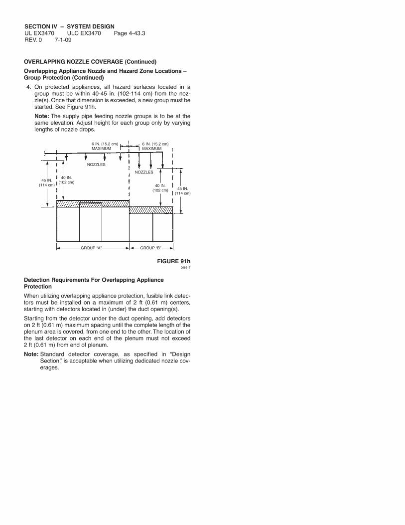
SECTION IV – SYSTEM DESIGNUL EX3470 ULC EX3470 Page 4-43.3REV. 0 7-1-09
OVERLAPPING NOZZLE COVERAGE (Continued)
Overlapping Appliance Nozzle and Hazard Zone Locations –Group Protection (Continued)
4. On protected appliances, all hazard surfaces located in agroup must be within 40-45 in. (102-114 cm) from the noz-zle(s). Once that dimension is exceeded, a new group must bestarted. See Figure 91h.
Note: The supply pipe feeding nozzle groups is to be at thesame elevation. Adjust height for each group only by varyinglengths of nozzle drops.
FIGURE 91h006917
Detection Requirements For Overlapping ApplianceProtection
When utilizing overlapping appliance protection, fusible link detec-tors must be installed on a maximum of 2 ft (0.61 m) centers, starting with detectors located in (under) the duct opening(s).
Starting from the detector under the duct opening, add detectorson 2 ft (0.61 m) maximum spacing until the complete length of theplenum area is covered, from one end to the other. The location ofthe last detector on each end of the plenum must not exceed2 ft (0.61 m) from end of plenum.
Note: Standard detector coverage, as specified in “DesignSection,” is acceptable when utilizing dedicated nozzle cov-erages.
GROUP “A”
6 IN. (15.2 cm)MAXIMUM
6 IN. (15.2 cm)MAXIMUM
NOZZLES
NOZZLES
GROUP “B”
45 IN.(114 cm)
45 IN.(114 cm)
40 IN.(102 cm)
40 IN.(102 cm)
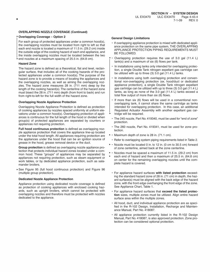
SECTION IV – SYSTEM DESIGNUL EX3470 ULC EX3470 Page 4-43.4
7-1-09 REV. 0
OVERLAPPING NOZZLE COVERAGE (Continued)
Overlapping Coverage – Option 2
For each group of protected appliances under a common hood(s),the overlapping nozzles must be located from right to left so thateach end nozzle is located a maximum of 11.5 in. (29.2 cm) insidethe outside edge of the cooking hazard of each end appliance, andthe inside overlapping nozzles must be located between the twoend nozzles at a maximum spacing of 25.5 in. (64.8 cm).
Hazard Zone
The hazard zone is defined as a theoretical, flat and level, rectan-gular surface, that includes all of the cooking hazards of the pro-tected appliances under a common hood(s). The purpose of thehazard zone is to provide a means of locating the appliances andthe overlapping nozzles, as well as aiming the overlapping noz-zles. The hazard zone measures 28 in. (711 mm) deep by thelength of the cooking hazard(s). The centerline of the hazard zonemust bisect the 28 in. (711 mm) depth (from front to back) and runfrom right-to-left for the full width of the hazard zone.
Overlapping Nozzle Appliance Protection
Overlapping Nozzle Appliance Protection is defined as protectionof cooking appliances by nozzles spaced uniformly at uniform ele-vations under a common hood(s). Overlapping protection of appli-ances is continuous for the full length of the hood or divided whengroup(s) of protected appliances are separated by counters orappliances not requiring protection.
Full hood continuous protection is defined as overlapping noz-zle appliance protection that covers the appliance line-up locatedunder the total hood length. All appliances requiring protection arethe appliances under the hood that can be an ignition source ofgrease in the hood, grease removal device or the duct.
Group protection is defined as overlapping nozzle appliance pro-tection that protects individual hazard zones located under a com-mon hood. These “groups” of appliances may be separated byappliances not requiring protection, such as steam equipment orwork tables, or by dedicated appliance protection, such as sala-mander broilers.
See Figure 95 (full hood continuous protection) and Figure 96(multiple group protection).
Dedicated Nozzle Appliance Protection
Appliance protection using dedicated nozzle coverage is definedas protection of cooking appliances with enclosed cooking haz-ards, such as upright broilers, which cannot be protected withoverlapping nozzles and therefore must be protected with nozzlesdedicated to the appliance.
General Design Limitations
• If overlapping appliance protection is mixed with dedicated appli-ance protection on the same pipe system, THE OVERLAPPINGAPPLIANCE PROTECTION PIPING REQUIREMENTS MUSTBE FOLLOWED.
• Overlapping protection requires the use of 3.0 gal (11.4 L)tank(s) and a maximum of six (6) flows per tank.
• In installations using tanks only intended for overlapping protec-tion, a single Double Tank nitrogen expellant gas cartridge canbe utilized with up to three (3) 3.0 gal (11.4 L) tanks.
• In installations using both overlapping protection and conven-tional non-overlapping protection (ex. hood/duct or dedicatedappliance protection), a single Double Tank nitrogen expellantgas cartridge can be utilized with up to three (3) 3.0 gal (11.4 L)tanks, as long as none of the 3.0 gal (11.4 L) tanks exceed atotal flow output of more than six (6) flows.
• If more than six (6) flows will be used in a conventional non-overlapping tank, it cannot share the same cartridge as tanksintended for overlapping protection. In this case, an additionalRegulated Actuator Assembly with another expellant gas car-tridge will be required.
• The 245 nozzle, Part No. 419340, must be used for “end of zone”protection.
• The 260 nozzle, Part No. 419341, must be used for zone pro-tection.
• Maximum depth of zone is 28 in. (71.1 cm).
• Refer to overlapping system piping requirements listed in Table 2.
• Nozzle must be located 0 in. to 12 in. (0 cm to 30.5 cm) forwardof zone centerline, aimed back at the zone centerline.
• Nozzles must be spaced a maximum of 11.5 in. (29.2 cm) fromeach end of hazard and then a maximum of 25.5 in. (64.8 cm)on center for the remaining overlapping nozzles until the com-plete hazard is covered.
• For appliance hazard surfaces with listed protection exceed-ing the standard hazard zone of 28 in. (71 cm) in depth, the haz-ard surface(s) must be aligned with the back edge of the hazardzone, with the front edge overhanging the front edge of the zone.See Appliance Chart, Table 1.
• For appliance hazard surfaces that exceed the listed protec-tion sizes, multiple zones must be utilized. Align entire hazardsurface area within the multiple zones.
• All hood, duct, and individual appliance protection are as speci-fied in the R-102 Design, Installation, Recharge and Mainten-ance Manual, Part No. 418087.
• All appliance protection currently listed in the R-102 DesignManual, Part No. 418087, is also approved protection. Zone pro-tection can be considered optional protection.

SECTION IV – SYSTEM DESIGNUL EX3470 ULC EX3470 Page 4-44REV. 6 7-1-09
OVERLAPPING NOZZLE COVERAGE (Continued)
TABLE 1Overlapping Nozzle Coverage (Zone Protection)
Appliance Type Maximum Cooking Hazard____________ ______________________
Fryer 34 in. (86.4 cm) Deep x 5.8 ft2 (0.5 m2)
Griddle 30 in. (76.2 cm) Deep x Unlimited Length
Range 30 in. (76.2 cm) Deep x Unlimited Length
Wok, Maximum 30 in. (76.2 cm) Diameter x 8 in.(20.3 cm) Deep
Wok, Minimum 11 in. (27.9 cm) Diameter x 3 in.(7.6 cm) Deep
Braising Pan/Tilt 34 in. (86.4 cm) Deep x UnlimitedSkillet* Length
Lava Rock 26 in. (66.0 cm) Deep x UnlimitedChar-Broiler (see Note 1) Length
Charcoal Broiler 30 in. (76.2 cm) Deep x Unlimited Length(4 in. (10.2 cm) Maximum Fuel Depth)
Mesquite Wood 30 in. (76.2 cm) Deep x Unlimited LengthBroiler (6 in. (15.2 cm) Maximum Fuel Depth)
Gas Radiant 36 in. (91.4 cm) Deep x UnlimitedChar-Broiler Length
Electric Char-Broiler 34 in. (86.4 cm) Deep x Unlimited Length* See Figure 92 for nozzle location
Note 1: Always try to place Lava Rock Char-Broiler(s) near the center of thezone. When the Lava Rock Char-Broiler is the first or last appliance in the zone,the outside edge of the broiler must not be more than 6 in. (15 cm) outside theend nozzle.
FIGURE 92006927
Overlapping Appliance Nozzle and Hazard Zone Locations
1. All overlapping appliance nozzles must be the 245 nozzle,Part No. 419340, for “end of zone” protection and the 260 noz-zle, Part No. 419341, for zone protection, and must be locatedunder a common hood at the same height above the hazardzone, in a straight line from right to left and aimed at the cen-terline of the hazard zone. The overlapping nozzle is used forboth continuous overlapping and multiple group overlappingprotection.
2. The hazard zone must be positioned (located) so that all appli-ance hazard surfaces are within the zone. For appliance haz-ard surfaces smaller than the standard hazard zone size, thehazard surface can be located anywhere within the standardhazard zone. For appliance hazard surfaces with listed pro-tection exceeding the standard hazard zone size of 28 in.(71 cm) in depth (see Table 1), the hazard surface(s) must bealigned with the back edge of the hazard zone, with the frontedge overhanging the front of the zone.
3. The overlapping appliance nozzles must be located 40 in. to45 in. (1 m to 1.1 m) above the top surface of the protectedappliances. See Figure 94.
Exception No. 1: Nozzle dimensions for wok protection aremeasured to bottom of wok. Exception No. 2: When usingoverlapping appliance nozzles in areas where there is a backshelf, the nozzle cannot be positioned in the shaded area asshown in Figure 93.
Also, back shelf must not extend more than 11 in. (27.9 cm)over the hazard zone and cannot be less than 18 in. (45.7 cm)above the hazard zone. See Figure 93.
FIGURE 93006914
COVER MUST NOTINTERFERE WITHEDGE OFDISCHARGEPATTERN
0-12 IN.(0-30.5 cm)
40-45 IN.(1-1.1 m)
ZONE CENTER LINE
ZONE
18 IN.(45.7 cm)MINIMUM
11 IN. (27.9 cm) MAXIMUM
CENTER LINE OFHAZARD ZONE
BACKSHELF
OVERLAPPING NOZZLE(S)CANNOT BE POSITIONEDIN THIS SHADED AREA
1210 8 6 4 2
454443424140
28 IN. (71.1 cm)
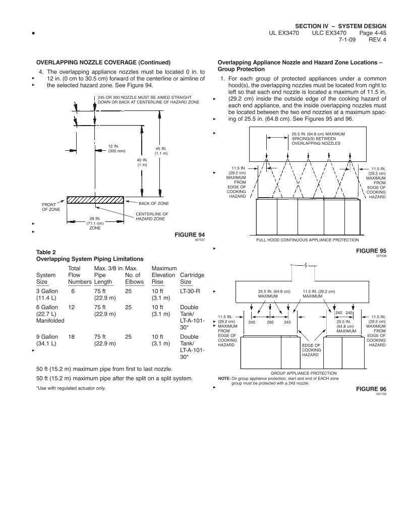
SECTION IV – SYSTEM DESIGNUL EX3470 ULC EX3470 Page 4-45
7-1-09 REV. 4
OVERLAPPING NOZZLE COVERAGE (Continued)
4. The overlapping appliance nozzles must be located 0 in. to12 in. (0 cm to 30.5 cm) forward of the centerline or aimline ofthe selected hazard zone. See Figure 94.
FIGURE 94007537
Table 2Overlapping System Piping Limitations
Total Max. 3/8 in. Max. MaximumSystem Flow Pipe No. of Elevation CartridgeSize Numbers Length Elbows Rise Size____ _______ ______ ______ ____ ____3 Gallon 6 75 ft 25 10 ft LT-30-R(11.4 L) (22.9 m) (3.1 m)
6 Gallon 12 75 ft 25 10 ft Double(22.7 L) (22.9 m) (3.1 m) Tank/Manifolded LT-A-101-
30*
9 Gallon 18 75 ft 25 10 ft Double(34.1 L) (22.9 m) (3.1 m) Tank/
LT-A-101-30*
50 ft (15.2 m) maximum pipe from first to last nozzle.
50 ft (15.2 m) maximum pipe after the split on a split system.
*Use with regulated actuator only.
Overlapping Appliance Nozzle and Hazard Zone Locations –Group Protection
1. For each group of protected appliances under a commonhood(s), the overlapping nozzles must be located from right toleft so that each end nozzle is located a maximum of 11.5 in.(29.2 cm) inside the outside edge of the cooking hazard ofeach end appliance, and the inside overlapping nozzles mustbe located between the two end nozzles at a maximum spac-ing of 25.5 in. (64.8 cm). See Figures 95 and 96.
FIGURE 95007538
FIGURE 96001720
11.5 IN.(29.2 cm)MAXIMUMFROMEDGE OFCOOKINGHAZARD
11.5 IN.(29.2 cm)
MAXIMUMFROM
EDGE OFCOOKING
HAZARD
GROUP APPLIANCE PROTECTIONNOTE: On group appliance protection, start and end of EACH zone
group must be protected with a 245 nozzle.
EDGE OFCOOKINGHAZARD
25.5 IN.(64.8 cm)MAXIMUM
25.5 IN. (64.8 cm)MAXIMUM
11.5 IN. (29.2 cm)MAXIMUM
25.5 IN. (64.8 cm) MAXIMUMSPACING(S) BETWEENOVERLAPPING NOZZLES
11.5 IN.(29.2 cm)
MAXIMUMFROM
EDGE OFCOOKING
HAZARD
11.5 IN.(29.2 cm)
MAXIMUMFROM
EDGE OFCOOKING
HAZARD
FULL HOOD CONTINUOUS APPLIANCE PROTECTION
245 260 245
245 245
28 IN.(71.1 cm)
ZONE
12 IN.(305 mm)
40 IN.(1 m)
45 IN.(1.1 m)
BACK OF ZONEFRONTOF ZONE
CENTERLINE OFHAZARD ZONE
245 OR 260 NOZZLE MUST BE AIMED STRAIGHTDOWN OR BACK AT CENTERLINE OF HAZARD ZONE

SECTION IV – SYSTEM DESIGNUL EX3470 ULC EX3470 Page 4-46REV. 6 7-1-09
OVERLAPPING NOZZLE COVERAGE (Continued)
Overlapping Appliance Nozzle and Hazard Zone Locations –Group Protection (Continued)
2. When obstructions are located adjacent to appliance(s) pro-tected by overlapping nozzles, the overlapping appliance noz-zle spacing must start with the appliance(s) adjacent to theobstruction. See Figure 97.
FIGURE 97001713
3. When an appliance requires dedicated protection with a pro-tected area intended for overlapping appliance nozzle protec-tion, the group protection option will be required for applianceson either side of the appliances using dedicated protection.Group protection using overlapping appliance nozzles mustbegin with the protected appliance(s) adjacent to the dedicat-ed appliance protected. An overlapping appliance nozzle(s)must be positioned within 11.5 in. (29.2 cm) of the edge(s) ofthe appliance hazard surface area(s) adjacent to the dedicat-ed nozzle protection. See Figure 98.
FIGURE 98001756
4. On protected appliances, all hazard surfaces located in agroup must be within 40-45 in. (1-1.1 m) from the nozzle(s).Once that dimension is exceeded, a new group must be start-ed. See Figure 99.
Note: The supply pipe feeding nozzle groups is to be at thesame elevation. Adjust height for each group only by varyinglengths of nozzle drops.
FIGURE 99007539
Detection Requirements For Overlapping ApplianceProtection
When utilizing overlapping appliance protection, fusible link detec-tors must be installed on a maximum of 2 ft (0.61 m) centers, starting with detectors located in (under) the duct opening(s).
Starting from the detector under the duct opening, add detectorson 2 ft (0.61 m) maximum spacing until the complete length of theplenum area is covered, from one end to the other. The location ofthe last detector on each end of the plenum must not exceed2 ft (0.61 m) from end of plenum.
Note: Standard detector placement can also be utilized whenusing overlapping protection. However, the overlapping detectoroption cannot be used when utilizing standard R-102 protection.Refer to Pages 4-57 and 4-58 for detector placement.
GROUP “A”
NOZZLES
NOZZLES
END OFZONE
11.5 IN. (29.2 cm)MAXIMUM
GROUP “B”
45 IN.(1.1 m)
45 IN.(1.1 m)
END OFZONE
40 IN.(1.0 m)
40 IN.(1.0 m)
NOTE: On group appliance protection, start and end of EACH zonegroup must be protected with a 245 nozzle.
11.5 IN.(29.2 cm)MAX.
OUTSIDEEDGE OFCOOKINGHAZARD
11.5 IN.(29.2 cm)MAX.
OBSTRUCTION
25.5 IN.(64.8 cm)
MAX.
25.5 IN.(64.8 cm)
MAX.
25.5 IN.(64.8 cm)
MAX.
25.5 IN.(64.8 cm)
MAX.
HAZARD AREA
245 260 260 260 245
NOTE: On continuous appliance protection, start and end with 245nozzles and 260 nozzle(s) in the middle.
11.5 IN.(29.2 cm)MAX.
EDGEOFCOOKINGHAZARD
EDGE OF COOKINGHAZARD
EDGEOFCOOKINGHAZARD
11.5 IN.(29.2 cm)MAX.
DEDICATED NOZZLEAPPLIANCE
25.5 IN.(64.8 cm)
MAX.
25.5 IN.(64.8 cm)
MAX.
11.5 IN. (29.2 cm)MAXIMUM
25.5 IN.(64.8 cm)
MAX.
11.5 IN.(29.2 cm) MAX.
NOTE: On group appliance protection, start and end of EACH zonegroup must be protected with a 245 nozzle.
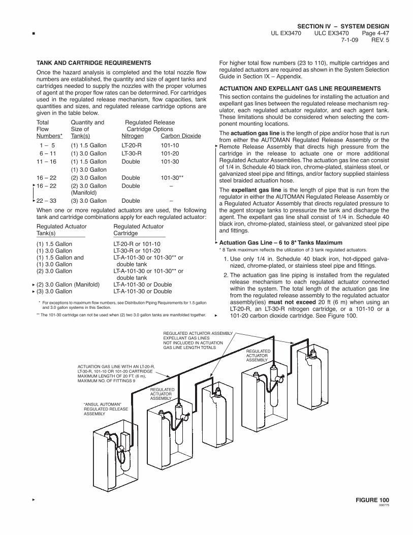
SECTION IV – SYSTEM DESIGNUL EX3470 ULC EX3470 Page 4-47
7-1-09 REV. 5
TANK AND CARTRIDGE REQUIREMENTS
Once the hazard analysis is completed and the total nozzle flownumbers are established, the quantity and size of agent tanks andcartridges needed to supply the nozzles with the proper volumesof agent at the proper flow rates can be determined. For cartridgesused in the regulated release mechanism, flow capacities, tankquantities and sizes, and regulated release cartridge options aregiven in the table below.
Total Quantity and Regulated ReleaseFlow Size of Cartridge OptionsNumbers* Tank(s) Nitrogen Carbon Dioxide
1 – 5 (1) 1.5 Gallon LT-20-R 101-106 – 11 (1) 3.0 Gallon LT-30-R 101-20
11 – 16 (1) 1.5 Gallon Double 101-30(1) 3.0 Gallon
16 – 22 (2) 3.0 Gallon Double 101-30**16 – 22 (2) 3.0 Gallon Double –
(Manifold)22 – 33 (3) 3.0 Gallon Double –
When one or more regulated actuators are used, the followingtank and cartridge combinations apply for each regulated actuator:
Regulated Actuator Regulated ActuatorTank(s) Cartridge_______________ ________________
(1) 1.5 Gallon LT-20-R or 101-10(1) 3.0 Gallon LT-30-R or 101-20(1) 1.5 Gallon and LT-A-101-30 or 101-30** or(1) 3.0 Gallon double tank(2) 3.0 Gallon LT-A-101-30 or 101-30** or
double tank(2) 3.0 Gallon (Manifold) LT-A-101-30 or Double(3) 3.0 Gallon LT-A-101-30 or Double
* For exceptions to maximum flow numbers, see Distribution Piping Requirements for 1.5 gallonand 3.0 gallon systems in this Section.
** The 101-30 cartridge can not be used when (2) two 3.0 gallon tanks are manifolded together.
For higher total flow numbers (23 to 110), multiple cartridges andregulated actuators are required as shown in the System SelectionGuide in Section IX – Appendix.
ACTUATION AND EXPELLANT GAS LINE REQUIREMENTSThis section contains the guidelines for installing the actuation andexpellant gas lines between the regulated release mechanism reg-ulator, each regulated actuator regulator, and each agent tank.These limitations should be considered when selecting the com-ponent mounting locations.
The actuation gas line is the length of pipe and/or hose that is runfrom either the AUTOMAN Regulated Release Assembly or theRemote Release Assembly that directs high pressure from thecartridge in the release to actuate one or more additionalRegulated Actuator Assemblies.The actuation gas line can consistof 1/4 in. Schedule 40 black iron, chrome-plated, stainless steel, orgalvanized steel pipe and fittings, and/or factory supplied stainlesssteel braided actuation hose.
The expellant gas line is the length of pipe that is run from theregulator in either the AUTOMAN Regulated Release Assembly ora Regulated Actuator Assembly that directs regulated pressure tothe agent storage tanks to pressurize the tank and discharge theagent. The expellant gas line shall consist of 1/4 in. Schedule 40black iron, chrome-plated, stainless steel, or galvanized steel pipeand fittings.
Actuation Gas Line – 6 to 8* Tanks Maximum* 8 Tank maximum reflects the utilization of 3 tank regulated actuators.
1. Use only 1/4 in. Schedule 40 black iron, hot-dipped galva-nized, chrome-plated, or stainless steel pipe and fittings.
2. The actuation gas line piping is installed from the regulatedrelease mechanism to each regulated actuator connectedwithin the system. The total length of the actuation gas linefrom the regulated release assembly to the regulated actuatorassembly(ies) must not exceed 20 ft (6 m) when using anLT-20-R, an LT-30-R nitrogen cartridge, or a 101-10 or a101-20 carbon dioxide cartridge. See Figure 100.
FIGURE 100000775
ACTUATION GAS LINE WITH AN LT-20-R,LT-30-R, 101-10 OR 101-20 CARTRIDGEMAXIMUM LENGTH OF 20 FT. (6 m),MAXIMUM NO. OF FITTINGS 9
REGULATED ACTUATOR ASSEMBLYEXPELLANT GAS LINESNOT INCLUDED IN ACTUATIONGAS LINE LENGTH TOTALS
REGULATEDACTUATORASSEMBLY
“ANSUL AUTOMAN”REGULATED RELEASEASSEMBLY
REGULATEDACTUATORASSEMBLY

SECTION IV – SYSTEM DESIGNUL EX3470 ULC EX3470 Page 4-48REV. 6 7-1-09
ACTUATION AND EXPELLENT GAS LINE REQUIREMENTS(Continued)
Actuation Gas Line – 6 to 8* Tanks Maximum (Continued)
3. If an expellant gas line is connected to the regulated releaseassembly along with an actuation gas line, the total combinedlength of the actuation and expellant gas line must notexceed 30 ft (9 m) when using a “double-tank” nitrogen car-tridge or a LT-A-101-30 nitrogen cartridge or a 101-30 carbondioxide cartridge. See Figure 101.
4. A combined total of nine fittings may be used in these lines,eight 90° elbows and one tee. Two 45° elbows equal one 90°elbow.
Actuation Gas Line – 10 to 15* Tanks Maximum* 15 Tank maximum reflects the utilization of 3 tank regulated actuators.
1. Use only 1/4 in. Schedule 40 black iron, hot-dipped galva-nized, chrome-plated, or stainless steel pipe and fittings.Note: Stainless steel hose and fittings can also be used. SeeComponent Section for detailed information.
FIGURE 101000262
2. The actuation gas line piping is installed from the 101 remotemechanical release to each R-102 regulated actuator assem-bly. The total length of the actuation gas line from the remotemechanical release to the regulated actuator assemblies mustnot exceed 100 ft (30.5 m).
3. A combined total of 20 elbows and 9 tees may be usedin these lines. Two 45° elbows equal one 90° elbow. SeeFigure 102.
4. Use only a 101-10 carbon dioxide cartridge in the 101 remotemechanical release.
5. A safety vent relief valve (Part No. 15677) is required in theactuation gas line to relieve residual pressure after actuation.
Actuation Gas Line – Using 1/4 in. Stainless Steel Hose* 15 Tank maximum reflects the utilization of 3 tank regulated actuators.
1. Maximum total length of hose cannot exceed 17.5 ft (5.3 m).
Note: A combination of 1/4 in. stainless steel braided hoseand 1/4 in. NPT pipe can be used as long as the total com-bined actuation gas line length does not exceed 17.5 ft(5.3 m). Stainless steel braided hose cannot be used forexpellant gas lines. See Figure 102 for additional details.
2. Maximum of 5 regulated actuators allowed
3. Actuated with remote release (Part No. 433485) or RegulatedRelease Assembly (Part No. 429853)
ACTUATOR AND EXPELLANT GAS LINES WITH A “DOUBLE TANK” CARTRIDGEOR A 101-30 CARTRIDGE OR A LT-A-101-30 CARTRIDGEMAXIMUM COMBINED LENGTH – 30 FT (9 m)MAXIMUM COMBINED FITTINGS – 9
REGULATEDACTUATORASSEMBLY
REGULATED ACTUATORASSEMBLY EXPELLANTGAS LINES NOT INCLUDEDIN COMBINED TOTALS
REGULATEDACTUATORASSEMBLY
“ANSUL AUTOMAN”REGULATED RELEASE ASSEMBLY
1/4 IN. STAINLESSSTEEL HOSE
MAXIMUM OF 5REGULATED ACTUATORS
REGULATED ACTUATORWITH TANK
NOTE: WHEN MULTIPLE RELEASE ASSEMBLIES ARE UTILIZED, A 1/4 IN. CHECK VALVE,PART NO. 25627, WILL BE REQUIRED AFTER EACH REGULATED RELEASE.
1/4 IN. STAINLESS STEEL HOSE OPTIONS
SAFETYRELIEF VALVE
MAXIMUM OF5 REMOTERELEASEMECHANISMS(PART NO.433485) ORONE (1)REGULATEDRELEASE (PARTNO. 429853)
CHECK VALVE
FIGURE 102000301
42 IN. (107 cm)MAX. HOSE
LENGTH (TYP.)
EXPELLANTGAS LINE
SAFETYRELIEF VALVE 1/4 IN. ACTUATION LINE –
100 FT (30.5 m) MAXIMUM
9 TEES MAXIMUM20 ELBOWSMAXIMUM
REMOTE RELEASE MECHANISMS(PART NO. 433485) 5 MAXIMUM
REGULATED ACTUATORWITH TANK
MAXIMUM OF 5REGULATEDACTUATORS
AGENT TANK
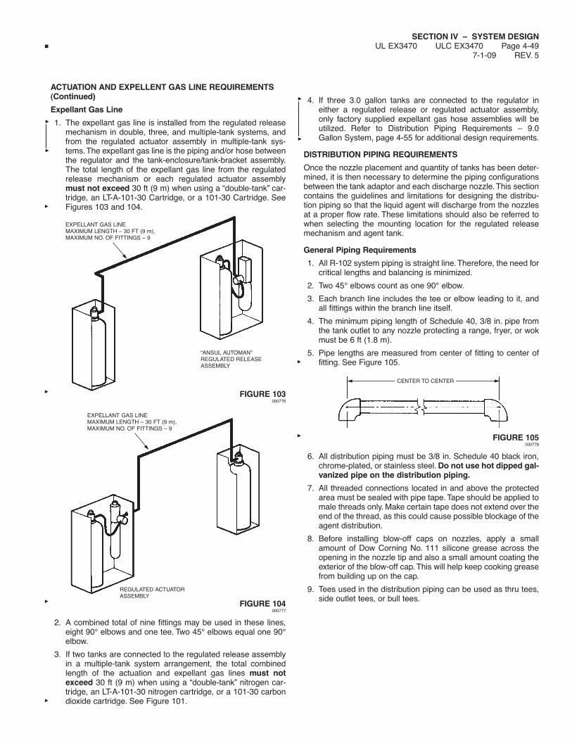
SECTION IV – SYSTEM DESIGNUL EX3470 ULC EX3470 Page 4-49
7-1-09 REV. 5
ACTUATION AND EXPELLENT GAS LINE REQUIREMENTS(Continued)
Expellant Gas Line
1. The expellant gas line is installed from the regulated releasemechanism in double, three, and multiple-tank systems, andfrom the regulated actuator assembly in multiple-tank sys-tems.The expellant gas line is the piping and/or hose betweenthe regulator and the tank-enclosure/tank-bracket assembly.The total length of the expellant gas line from the regulatedrelease mechanism or each regulated actuator assemblymust not exceed 30 ft (9 m) when using a “double-tank” car-tridge, an LT-A-101-30 Cartridge, or a 101-30 Cartridge. SeeFigures 103 and 104.
FIGURE 103000776
FIGURE 104000777
2. A combined total of nine fittings may be used in these lines,eight 90° elbows and one tee. Two 45° elbows equal one 90°elbow.
3. If two tanks are connected to the regulated release assemblyin a multiple-tank system arrangement, the total combinedlength of the actuation and expellant gas lines must notexceed 30 ft (9 m) when using a “double-tank” nitrogen car-tridge, an LT-A-101-30 nitrogen cartridge, or a 101-30 carbondioxide cartridge. See Figure 101.
4. If three 3.0 gallon tanks are connected to the regulator ineither a regulated release or regulated actuator assembly,only factory supplied expellant gas hose assemblies will beutilized. Refer to Distribution Piping Requirements – 9.0Gallon System, page 4-55 for additional design requirements.
DISTRIBUTION PIPING REQUIREMENTS
Once the nozzle placement and quantity of tanks has been deter-mined, it is then necessary to determine the piping configurationsbetween the tank adaptor and each discharge nozzle. This sectioncontains the guidelines and limitations for designing the distribu-tion piping so that the liquid agent will discharge from the nozzlesat a proper flow rate. These limitations should also be referred towhen selecting the mounting location for the regulated releasemechanism and agent tank.
General Piping Requirements
1. All R-102 system piping is straight line.Therefore, the need forcritical lengths and balancing is minimized.
2. Two 45° elbows count as one 90° elbow.
3. Each branch line includes the tee or elbow leading to it, andall fittings within the branch line itself.
4. The minimum piping length of Schedule 40, 3/8 in. pipe fromthe tank outlet to any nozzle protecting a range, fryer, or wokmust be 6 ft (1.8 m).
5. Pipe lengths are measured from center of fitting to center offitting. See Figure 105.
FIGURE 105000778
6. All distribution piping must be 3/8 in. Schedule 40 black iron,chrome-plated, or stainless steel. Do not use hot dipped gal-vanized pipe on the distribution piping.
7. All threaded connections located in and above the protectedarea must be sealed with pipe tape. Tape should be applied tomale threads only. Make certain tape does not extend over theend of the thread, as this could cause possible blockage of theagent distribution.
8. Before installing blow-off caps on nozzles, apply a smallamount of Dow Corning No. 111 silicone grease across theopening in the nozzle tip and also a small amount coating theexterior of the blow-off cap. This will help keep cooking greasefrom building up on the cap.
9. Tees used in the distribution piping can be used as thru tees,side outlet tees, or bull tees.
EXPELLANT GAS LINEMAXIMUM LENGTH – 30 FT (9 m),MAXIMUM NO. OF FITTINGS – 9
“ANSUL AUTOMAN”REGULATED RELEASEASSEMBLY
EXPELLANT GAS LINEMAXIMUM LENGTH – 30 FT (9 m),MAXIMUM NO. OF FITTINGS – 9
REGULATED ACTUATORASSEMBLY
CENTER TO CENTER

SECTION IV – SYSTEM DESIGNUL EX3470 ULC EX3470 Page 4-50REV. 5 7-1-09
DISTRIBUTION PIPING REQUIREMENTS (Continued)
Supply and Branch Line Identification
The R-102 distribution piping network is broken down into fourspecific pipe runs: the Supply Line, the Duct Branch Line,the Plenum Branch Line, and the Appliance Branch Line. SeeFigure 106.
FIGURE 106000779
SUPPLY LINE
The Supply Line is defined as the length of pipe which runs fromthe agent tank outlet to the last branch line (whether a duct, appli-ance, or plenum branch line). This includes all supply line fittingsexcept for the tees or elbows leading to the branch lines. SeeFigures 106 and 107.
FIGURE 107000780
NOTE: THESE ARE EXAMPLES ONLY. OTHER CONFIGURATIONS CAN BE DESIGNED.
DUCTBRANCH LINE
SUPPLYLINE
PLENUMBRANCH LINE
APPLIANCEBRANCH LINE
NOTE: THIS IS A CONCEPTUAL DRAWING ONLY.THIS IS NOT AN ACTUAL INSTALLATION.
END OFSUPPLY LINE
END OFSUPPLY LINE
END OFSUPPLY LINE
END OFSUPPLY LINE
SUPPLYLINE TEE
(NOZZLES FORPLENUMPROTECTION)
END OFSUPPLY LINE
SUPPLYLINE TEE
BRANCH LINE CANNOTSTART AHEAD OF ASUPPLY LINE TEE
BRANCH LINE CANNOTSTART AHEAD OF ASUPPLY LINE TEE
(NOZZLES FORPLENUMPROTECTION)
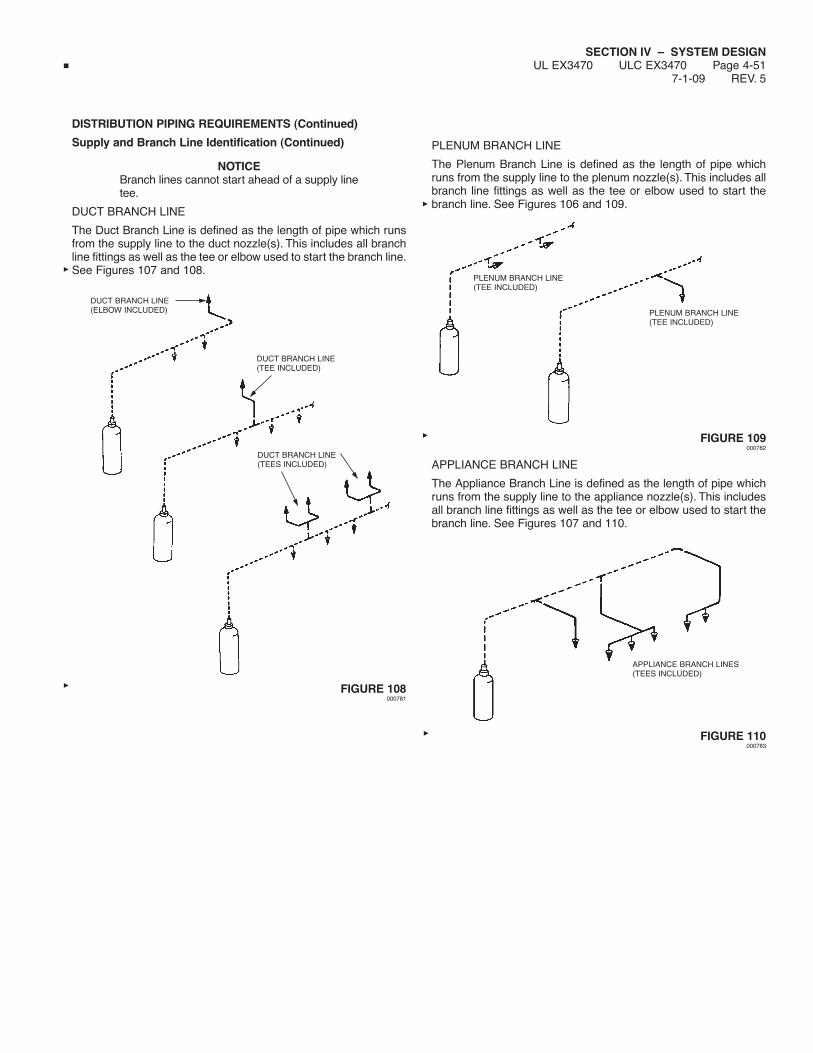
SECTION IV – SYSTEM DESIGNUL EX3470 ULC EX3470 Page 4-51
7-1-09 REV. 5
DISTRIBUTION PIPING REQUIREMENTS (Continued)
Supply and Branch Line Identification (Continued)
NOTICEBranch lines cannot start ahead of a supply linetee.
DUCT BRANCH LINE
The Duct Branch Line is defined as the length of pipe which runsfrom the supply line to the duct nozzle(s). This includes all branchline fittings as well as the tee or elbow used to start the branch line.See Figures 107 and 108.
FIGURE 108000781
PLENUM BRANCH LINE
The Plenum Branch Line is defined as the length of pipe whichruns from the supply line to the plenum nozzle(s). This includes allbranch line fittings as well as the tee or elbow used to start thebranch line. See Figures 106 and 109.
FIGURE 109000782
APPLIANCE BRANCH LINE
The Appliance Branch Line is defined as the length of pipe whichruns from the supply line to the appliance nozzle(s). This includesall branch line fittings as well as the tee or elbow used to start thebranch line. See Figures 107 and 110.
FIGURE 110000783
DUCT BRANCH LINE(ELBOW INCLUDED)
DUCT BRANCH LINE(TEE INCLUDED)
DUCT BRANCH LINE(TEES INCLUDED)
PLENUM BRANCH LINE(TEE INCLUDED)
PLENUM BRANCH LINE(TEE INCLUDED)
APPLIANCE BRANCH LINES(TEES INCLUDED)

SECTION IV – SYSTEM DESIGNUL EX3470 ULC EX3470 Page 4-52REV. 4 7-1-09
DISTRIBUTION PIPING REQUIREMENTS (Continued)
Distribution Piping Requirements – 1.5 Gallon System
DUCT, PLENUM, AND APPLIANCE PROTECTION
1. This option allows for duct protection, plenum protection,appliance protection, or any combination. However, only one(1) duct nozzle may be used, either a 1W or a 2W, nozzle.
2. All distribution piping, supply and branch, must be 3/8 in.Schedule 40 black iron, chrome-plated, or stainless steel.
3. Each 1.5 gallon tank allows a maximum of five flow numbers.*
4. The pipe length between the start of the first branch line andthe start of the last branch line must not exceed 8 ft (2.4 m).When the supply line is split, the combined length of bothlegs of the supply line (start of first branch line to start of lastbranch line) must not exceed 8 ft (2.4 m). See Figure 111.
5. The combined length of all branch lines must not exceed 22 ft(6.7 m). See Figure 112.
6. The requirements of the following table must not be exceeded:
Duct Plenum ApplianceRequirements Supply Branch Line Branch Line Branch Line
Pipe Size 3/8 in. 3/8 in. 3/8 in. 3/8 in.
Maximum Length 40 ft 6 ft 4 ft 10 ft(12.2 m) (1.8 m) (1.2 m) (3 m)
Maximum Rise 6 ft 4 ft 2 ft 2 ft(1.8 m) (1.2 m) (0.6 m) (0.6 m)
Maximum 90° Elbow 9 4 4 6
Maximum Tees 1 1 2 3
Maximum Flow Numbers 5* 2 2 3
* Exceptions:1. Six (6) flow numbers are allowed when a duct branch line is the last branch line on the piping network and no 1N nozzles are used to protect woks or griddles.2. Six (6) flow numbers are allowed when six (6) 1N nozzles are used and none of the nozzles are used to protect woks, griddles, ranges, and salamanders.
NOTE: Only five (5) flow numbers are allowed if a 1N nozzle is used for wok, griddle, range, or salamander protection.3. Six (6) flow numbers are allowed when only two (2) 3N nozzles are used.
FIGURE 111000784
FIGURE 112000785
SUPPLYLINE TEE
START OF FIRSTBRANCH LINE
START OF LASTBRANCH LINE
TOTAL LENGTHMUST NOTEXCEED 8 FT(2.4 m)
START OF LASTBRANCH LINE
START OF FIRSTBRANCH LINE
1W NOZZLE
1N NOZZLE
COMBINED LENGTH MUSTNOT EXCEED 22 FT. (6.7 m)
1N NOZZLE
(BRANCH LINES IN BOLD)
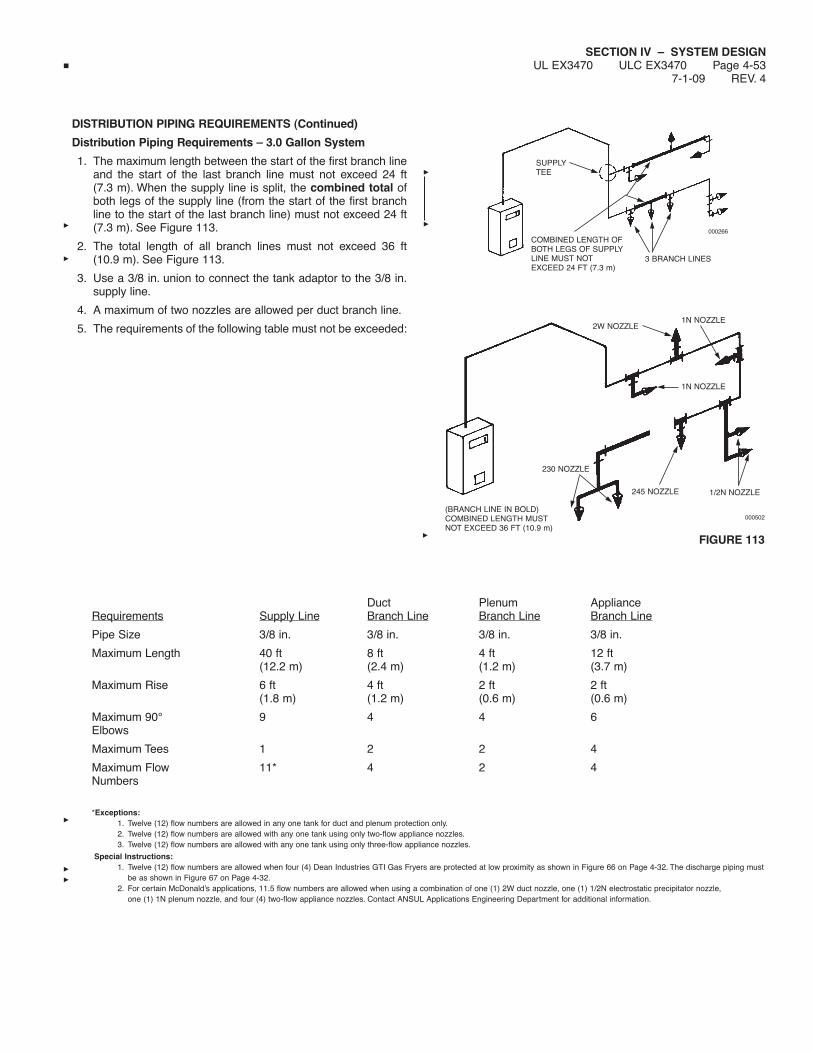
SECTION IV – SYSTEM DESIGNUL EX3470 ULC EX3470 Page 4-53
7-1-09 REV. 4
DISTRIBUTION PIPING REQUIREMENTS (Continued)
Distribution Piping Requirements – 3.0 Gallon System
1. The maximum length between the start of the first branch lineand the start of the last branch line must not exceed 24 ft(7.3 m). When the supply line is split, the combined total ofboth legs of the supply line (from the start of the first branchline to the start of the last branch line) must not exceed 24 ft(7.3 m). See Figure 113.
2. The total length of all branch lines must not exceed 36 ft(10.9 m). See Figure 113.
3. Use a 3/8 in. union to connect the tank adaptor to the 3/8 in.supply line.
4. A maximum of two nozzles are allowed per duct branch line.
5. The requirements of the following table must not be exceeded:
Duct Plenum ApplianceRequirements Supply Line Branch Line Branch Line Branch Line
Pipe Size 3/8 in. 3/8 in. 3/8 in. 3/8 in.
Maximum Length 40 ft 8 ft 4 ft 12 ft(12.2 m) (2.4 m) (1.2 m) (3.7 m)
Maximum Rise 6 ft 4 ft 2 ft 2 ft(1.8 m) (1.2 m) (0.6 m) (0.6 m)
Maximum 90° 9 4 4 6Elbows
Maximum Tees 1 2 2 4
Maximum Flow 11* 4 2 4Numbers
*Exceptions:1. Twelve (12) flow numbers are allowed in any one tank for duct and plenum protection only.2. Twelve (12) flow numbers are allowed with any one tank using only two-flow appliance nozzles.3. Twelve (12) flow numbers are allowed with any one tank using only three-flow appliance nozzles.
Special Instructions:1. Twelve (12) flow numbers are allowed when four (4) Dean Industries GTI Gas Fryers are protected at low proximity as shown in Figure 66 on Page 4-32. The discharge piping must
be as shown in Figure 67 on Page 4-32.2. For certain McDonald’s applications, 11.5 flow numbers are allowed when using a combination of one (1) 2W duct nozzle, one (1) 1/2N electrostatic precipitator nozzle,
one (1) 1N plenum nozzle, and four (4) two-flow appliance nozzles. Contact ANSUL Applications Engineering Department for additional information.
FIGURE 113
SUPPLYTEE
COMBINED LENGTH OFBOTH LEGS OF SUPPLYLINE MUST NOTEXCEED 24 FT (7.3 m)
3 BRANCH LINES
000266
2W NOZZLE1N NOZZLE
1N NOZZLE
230 NOZZLE
245 NOZZLE 1/2N NOZZLE
(BRANCH LINE IN BOLD)COMBINED LENGTH MUSTNOT EXCEED 36 FT (10.9 m)
000502

SECTION IV – SYSTEM DESIGNUL EX3470 ULC EX3470 Page 4-54REV. 5 7-1-09
DISTRIBUTION PIPING REQUIREMENTS (Continued)
Distribution Piping Requirements – 6.0 Gallon ManifoldedSystem
As an option to piping two (2) 3.0 gallon tanks separately, two (2)3.0 gallon tanks can be manifolded together to share a commonagent distribution line. Only (2) 3.0 gallon tanks connected to thesame regulator can be manifolded. The following requirementsmust be met when manifolding:
1. All piping must be 3/8 in. Schedule 40.
2. See Figure 115 for tank connections.
3. The length of supply line piping between the start of the firstbranch line and the start of the last branch line must notexceed 24 ft (7.3 m). See Figure 94. When the supply line issplit, the combined total of both legs of the supply line (fromthe start of the first branch line to the start of the last branchline) must not exceed 24 ft (7.3 m).
4. The combined length of all branch lines must not exceed 36 ft(10.9 m). See Figure 114.
5. A maximum of 22 flow numbers are allowed.
6. The requirements of the following table must not be exceeded.
FIGURE 114000267
Duct Plenum ApplianceRequirements Supply Line Branch Line Branch Line Branch Line
Pipe Size 3/8 in. 3/8 in. 3/8 in. 3/8 in.
Maximum Length 32 ft 8 ft 4 ft 12 ft(9.7 m) (2.4 m) (1.2 m) (3.7 m)
Maximum Rise 6 ft 4 ft 2 ft 2 ft(1.8 m) (1.2 m) (0.6 m) (0.6 m)
Maximum 90° 8 4 4 6Elbows
Maximum Tees 2 2 2 4
Maximum Flow 22 4 2 4Numbers
LENGTH OF PIPING MUST NOT EXCEED 24 FT.(7.3 m) FROM START OF FIRST BRANCH LINETO START OF LAST BRANCH LINE
START OF LASTBRANCH LINE
2WNOZZLES 1N
NOZZLE
1NNOZZLE
1NNOZZLE
1NNOZZLE
2 FLOW APPLIANCE NOZZLE
(BRANCH LINES IN BOLD)COMBINED LENGTH MUST NOT EXCEED 36 FT (10.9 m)
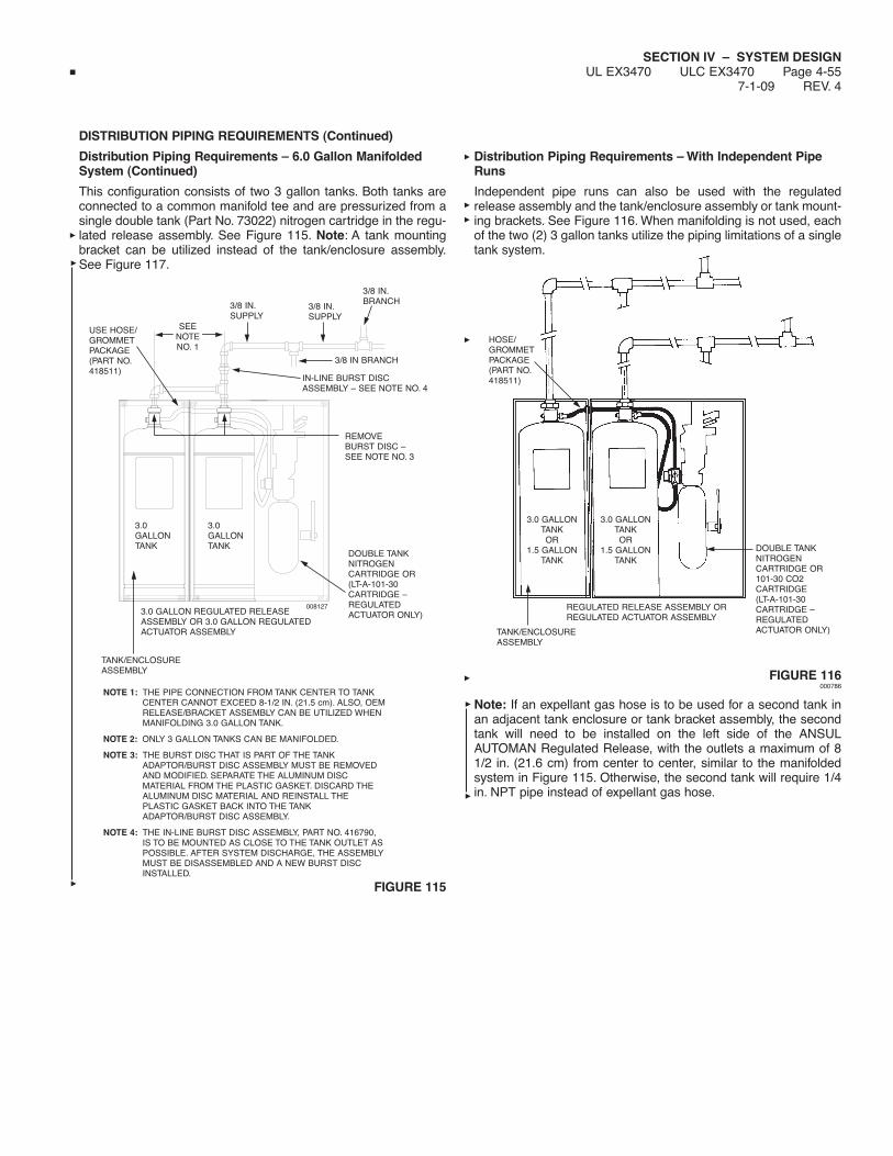
SECTION IV – SYSTEM DESIGNUL EX3470 ULC EX3470 Page 4-55
7-1-09 REV. 4
DISTRIBUTION PIPING REQUIREMENTS (Continued)
Distribution Piping Requirements – 6.0 Gallon ManifoldedSystem (Continued)
This configuration consists of two 3 gallon tanks. Both tanks areconnected to a common manifold tee and are pressurized from asingle double tank (Part No. 73022) nitrogen cartridge in the regu-lated release assembly. See Figure 115. Note: A tank mountingbracket can be utilized instead of the tank/enclosure assembly.See Figure 117.
FIGURE 115
Distribution Piping Requirements – With Independent PipeRuns
Independent pipe runs can also be used with the regulatedrelease assembly and the tank/enclosure assembly or tank mount-ing brackets. See Figure 116. When manifolding is not used, eachof the two (2) 3 gallon tanks utilize the piping limitations of a singletank system.
FIGURE 116000786
Note: If an expellant gas hose is to be used for a second tank inan adjacent tank enclosure or tank bracket assembly, the secondtank will need to be installed on the left side of the ANSULAUTOMAN Regulated Release, with the outlets a maximum of 81/2 in. (21.6 cm) from center to center, similar to the manifoldedsystem in Figure 115. Otherwise, the second tank will require 1/4in. NPT pipe instead of expellant gas hose.
HOSE/GROMMETPACKAGE(PART NO.418511)
3.0 GALLONTANKOR
1.5 GALLONTANK
3.0 GALLONTANKOR
1.5 GALLONTANK
DOUBLE TANKNITROGENCARTRIDGE OR101-30 CO2CARTRIDGE(LT-A-101-30CARTRIDGE –REGULATEDACTUATOR ONLY)
REGULATED RELEASE ASSEMBLY ORREGULATED ACTUATOR ASSEMBLY
TANK/ENCLOSUREASSEMBLY
008127
USE HOSE/GROMMETPACKAGE(PART NO.418511)
SEENOTENO. 1
3/8 IN.SUPPLY
3/8 IN.SUPPLY
3/8 IN.BRANCH
3/8 IN BRANCH
DOUBLE TANKNITROGENCARTRIDGE OR(LT-A-101-30CARTRIDGE –REGULATEDACTUATOR ONLY)
IN-LINE BURST DISCASSEMBLY – SEE NOTE NO. 4
REMOVEBURST DISC –SEE NOTE NO. 3
3.0 GALLON REGULATED RELEASEASSEMBLY OR 3.0 GALLON REGULATEDACTUATOR ASSEMBLY
TANK/ENCLOSUREASSEMBLY
3.0GALLONTANK
3.0GALLONTANK
NOTE 1: THE PIPE CONNECTION FROM TANK CENTER TO TANKCENTER CANNOT EXCEED 8-1/2 IN. (21.5 cm). ALSO, OEMRELEASE/BRACKET ASSEMBLY CAN BE UTILIZED WHENMANIFOLDING 3.0 GALLON TANK.
NOTE 2: ONLY 3 GALLON TANKS CAN BE MANIFOLDED.
NOTE 3: THE BURST DISC THAT IS PART OF THE TANKADAPTOR/BURST DISC ASSEMBLY MUST BE REMOVEDAND MODIFIED. SEPARATE THE ALUMINUM DISCMATERIAL FROM THE PLASTIC GASKET. DISCARD THEALUMINUM DISC MATERIAL AND REINSTALL THEPLASTIC GASKET BACK INTO THE TANKADAPTOR/BURST DISC ASSEMBLY.
NOTE 4: THE IN-LINE BURST DISC ASSEMBLY, PART NO. 416790,IS TO BE MOUNTED AS CLOSE TO THE TANK OUTLET ASPOSSIBLE. AFTER SYSTEM DISCHARGE, THE ASSEMBLYMUST BE DISASSEMBLED AND A NEW BURST DISCINSTALLED.

SECTION IV – SYSTEM DESIGNUL EX3470 ULC EX3470 Page 4-56REV. 4 7-1-09
DISTRIBUTION PIPING REQUIREMENTS (Continued)
Distribution Piping Requirements – 9.0 Gallon System
This optional configuration consists only of three 3-gallon tanks, allpressurized from a single double-tank nitrogen cartridge withexpellant gas hoses connected as shown in Figure 117. Tanks No.1 and No. 2 must be connected directly to the regulator with sepa-rate expellant gas hoses and Tank No. 3 must be connected toTank No. 2 with a third expellant gas hose as shown in Figure 117.Each tank must be connected to an independent distribution pip-ing network as shown in Figure 117. Distribution piping require-ments for each network must be as follows:
1. The maximum length between the start of the first branch lineand the start of the last branch line must not exceed 24 ft(7.3 m). When the supply line is split, the combined total ofboth legs of the supply line (from the start of the first branchline to the start of the last branch line) must not exceed 24 ft(7.3 m). See Figure 113.
2. The total length of all branch lines must not exceed 36 ft(10.9 m). See Figure 113.
3. Use a 3/8 in. union to connect the tank adaptor to the 3/8 in.supply line.
4. A maximum of two nozzles are allowed per duct branch line.
5. When using this 9.0 gallon system configuration, no mani-folding of distribution piping is allowed.
6. When an ANSUL AUTOMAN Regulated Release is utilized inthis configuration, additional regulator actuators cannot beused.
7. Only 3 gallon tanks can be utilized in this configuration.
8. The requirements of the following table must not be exceededfor each 3 gallon tank:
Duct Plenum ApplianceRequirements Supply Line Branch Line Branch Line Branch Line
Pipe Size 3/8 in. 3/8 in. 3/8 in. 3/8 in.
Maximum Length 40 ft 8 ft 4 ft 12 ft(12.2 m) (2.4 m) (1.2 m) (3.7 m)
Maximum Rise 6 ft 4 ft 2 ft 2 ft(1.8 m) (1.2 m) (0.6 m) (0.6 m)
Maximum 90° 9 4 4 6Elbows
Maximum Tees 1 2 2 4
Maximum Flow 11* 4 2 4Numbers
*Exceptions:1. Twelve (12) flow numbers are allowed in any one tank for duct and plenum protection ONLY.2. Twelve (12) flow numbers are allowed with any one tank using only two-flow appliance nozzles.3. Twelve (12) flow numbers are allowed with any one tank using only three-flow appliance nozzles.
Special Instructions:1. When four (4) Dean Industries GTI Gas Fryers are protected at low proximity as shown in Figure 66 on Page 4-32, the discharge piping must be as shown in Figure 67 on
Page 4-32.2. For certain McDonald’s applications, 11.5 flow numbers are allowed when using a combination of one (1) 2W duct nozzle, one (1) 1/2N electrostatic precipitator nozzle,
one (1) 1N plenum nozzle, and four (4) two-flow appliance nozzles. Contact Ansul Applications Engineering Department for additional information.
FIGURE 117008126
3.0GALLONTANKNO. 3
3.0GALLONTANKNO. 2
3.0GALLONTANKNO. 1
3 GALLON REGULATEDRELEASE ASSEMBLY,OR 3 GALLONREGULATED ACTUATORASSEMBLY
TWO TANK ENCLOSUREASSEMBLY PART NO.430324 (INCLUDES (2)HOSES AND (2)GROMMETS)
DOUBLE TANK NITROGENCARTRIDGE OR LT-A-101-30 CARTRIDGE (REGULATED ACTUATORONLY)
NOTE: WHEN THREE (3) 3.0 GALLON TANKS ARE CONNECTED TO ONE (1)AUTOMAN REGULATED RELEASE ASSEMBLY, NO ADDITIONALREGULATED ACTUATOR(S) ASSEMBLIES CAN BE USED.

SECTION IV – SYSTEM DESIGNUL EX3470 ULC EX3470 Page 4-57
7-1-09 REV. 2
DETECTION SYSTEM REQUIREMENTS
Once the fire suppression system design has been determined, adetection system design must be completed. This section containsguidelines and limitations for detection system installation.
Detector Identification
The two types of detectors are distinguished from each other bytheir location in the detection system.
1. The Terminal Detector (Part No. 417368) is the last in a seriesof detectors, or the only detector used in a single-detector sys-tem. This detector is thus named because it is at the point atwhich the wire rope ends, or “terminates.”
2. A Series Detector (Part No. 417369) is any detector located in-line between the regulated release mechanism and the termi-nal detector.
Detector/Pulley Elbow/Conduit Off-Set Design Limitations
1. Conduit runs, pulley elbows, and number of detectors per sys-tem must be within the approved system guidelines. The fol-lowing requirements must not be exceeded:
Maximum Maximum MaximumNumber of Number of Length of 1/2Detectors Elbows in. Conduitper System per System per System
Scissors Style 15 20 150 ft (45.7 m)Detector(WithoutOff-Set Conduit
Scissors Style 15 16 150 ft (45.7 m)Detector (WithOff-Set Conduit
2. If the hazard requires more than 15 detectors, up to five 101Remote Releases (Part No. 433485) can be used for systemactuation. Each 101 remote release allows the use of a maxi-mum of 15 “scissor” style detectors (14 series and 1 terminal)for a total of 75 detectors if needed.
Detector Placement Requirements
EXHAUST DUCTS
Each exhaust duct must have at least one detector installed in theduct entrance, located in the airstream of the cooking vapors, or ata maximum of 20 ft (6.1 m) into the duct opening. See Figure 118.
FIGURE 118000271
NOTICEWhen gas appliances are used and the fluegases from the burner are exhausted into theduct, the detector must be kept out of the airstream of these exhaust gases. These gasescan be very hot and could actuate the systemunnecessarily.
Duct openings that are long and narrow or largeenough to require multiple duct nozzles mayrequire additional detectors.
ELECTROSTATIC PRECIPITATOR
If an electrostatic precipitator is located at or near the base of theexhaust duct, it is necessary to locate a detector below the pre-cipitator, at the base of the duct, and also locate one in the duct,just above the precipitator. See Figure 119.
When installing the detector bracket and system conduit, makecertain they do not interfere with the operation of the precipitator.
Note: On secondary filtration units utilizing multiple filterstages/media, contact Ansul Technical Services for instructions.
FIGURE 119000268
20 FT. (6 m)MAXIMUM
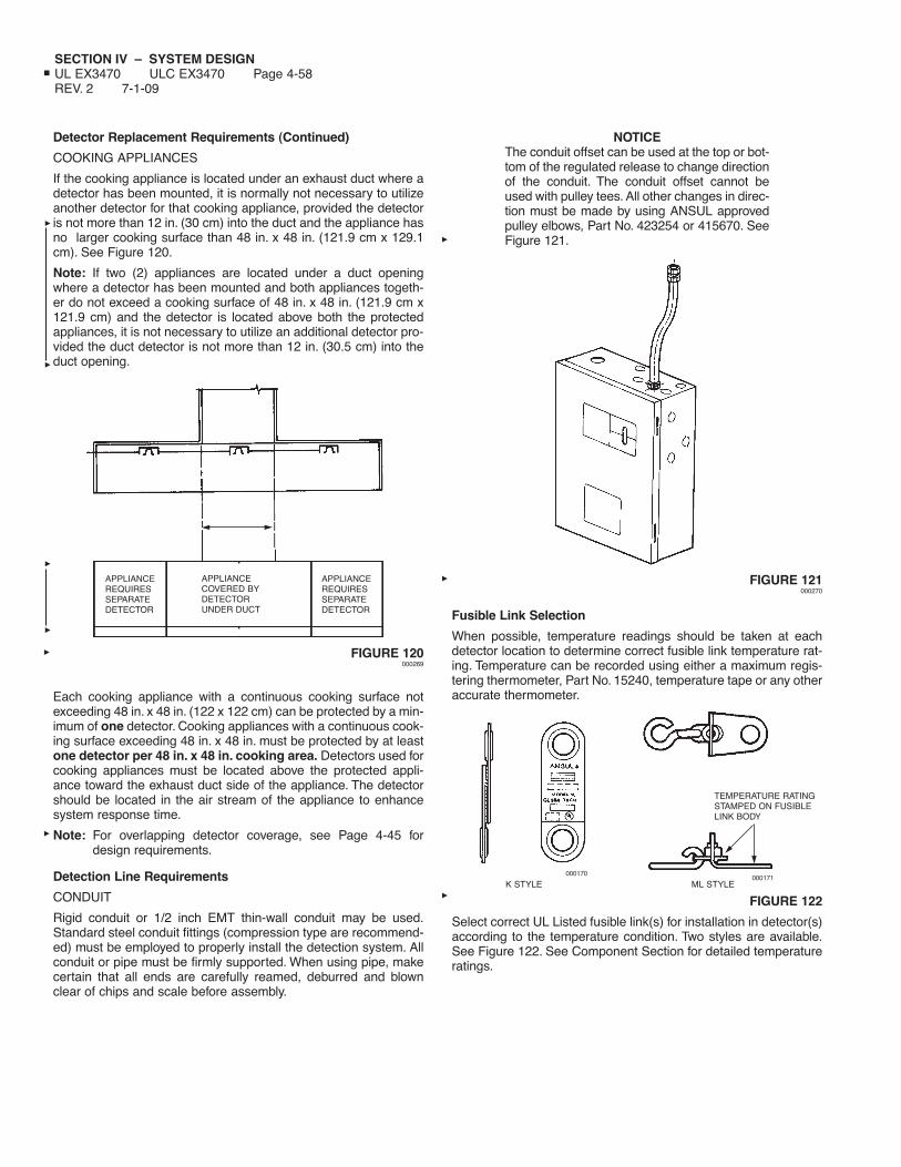
SECTION IV – SYSTEM DESIGNUL EX3470 ULC EX3470 Page 4-58REV. 2 7-1-09
Detector Replacement Requirements (Continued)
COOKING APPLIANCES
If the cooking appliance is located under an exhaust duct where adetector has been mounted, it is normally not necessary to utilizeanother detector for that cooking appliance, provided the detectoris not more than 12 in. (30 cm) into the duct and the appliance hasno larger cooking surface than 48 in. x 48 in. (121.9 cm x 129.1cm). See Figure 120.
Note: If two (2) appliances are located under a duct openingwhere a detector has been mounted and both appliances togeth-er do not exceed a cooking surface of 48 in. x 48 in. (121.9 cm x121.9 cm) and the detector is located above both the protectedappliances, it is not necessary to utilize an additional detector pro-vided the duct detector is not more than 12 in. (30.5 cm) into theduct opening.
FIGURE 120000269
Each cooking appliance with a continuous cooking surface notexceeding 48 in. x 48 in. (122 x 122 cm) can be protected by a min-imum of one detector. Cooking appliances with a continuous cook-ing surface exceeding 48 in. x 48 in. must be protected by at leastone detector per 48 in. x 48 in. cooking area. Detectors used forcooking appliances must be located above the protected appli-ance toward the exhaust duct side of the appliance. The detectorshould be located in the air stream of the appliance to enhancesystem response time.
Note: For overlapping detector coverage, see Page 4-45 fordesign requirements.
Detection Line Requirements
CONDUIT
Rigid conduit or 1/2 inch EMT thin-wall conduit may be used.Standard steel conduit fittings (compression type are recommend-ed) must be employed to properly install the detection system. Allconduit or pipe must be firmly supported. When using pipe, makecertain that all ends are carefully reamed, deburred and blownclear of chips and scale before assembly.
NOTICEThe conduit offset can be used at the top or bot-tom of the regulated release to change directionof the conduit. The conduit offset cannot beused with pulley tees. All other changes in direc-tion must be made by using ANSUL approvedpulley elbows, Part No. 423254 or 415670. SeeFigure 121.
FIGURE 121000270
Fusible Link Selection
When possible, temperature readings should be taken at eachdetector location to determine correct fusible link temperature rat-ing. Temperature can be recorded using either a maximum regis-tering thermometer, Part No. 15240, temperature tape or any otheraccurate thermometer.
FIGURE 122
Select correct UL Listed fusible link(s) for installation in detector(s)according to the temperature condition. Two styles are available.See Figure 122. See Component Section for detailed temperatureratings.
APPLIANCEREQUIRESSEPARATEDETECTOR
APPLIANCEREQUIRESSEPARATEDETECTOR
K STYLE000170
ML STYLE000171
TEMPERATURE RATINGSTAMPED ON FUSIBLELINK BODY
APPLIANCECOVERED BYDETECTORUNDER DUCT
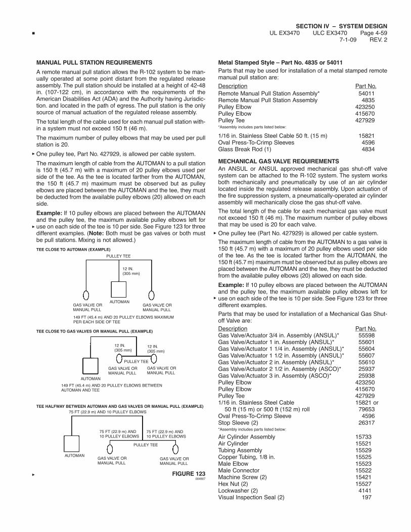
SECTION IV – SYSTEM DESIGNUL EX3470 ULC EX3470 Page 4-59
7-1-09 REV. 2
MANUAL PULL STATION REQUIREMENTS
A remote manual pull station allows the R-102 system to be man-ually operated at some point distant from the regulated releaseassembly. The pull station should be installed at a height of 42-48in. (107-122 cm), in accordance with the requirements of theAmerican Disabilities Act (ADA) and the Authority having Jurisdic-tion. and located in the path of egress. The pull station is the onlysource of manual actuation of the regulated release assembly.
The total length of the cable used for each manual pull station with-in a system must not exceed 150 ft (46 m).
The maximum number of pulley elbows that may be used per pullstation is 20.
One pulley tee, Part No. 427929, is allowed per cable system.
The maximum length of cable from the AUTOMAN to a pull stationis 150 ft (45.7 m) with a maximum of 20 pulley elbows used perside of the tee. As the tee is located farther from the AUTOMAN,the 150 ft (45.7 m) maximum must be observed but as pulleyelbows are placed between the AUTOMAN and the tee, they mustbe deducted from the available pulley elbows (20) allowed on eachside.
Example: If 10 pulley elbows are placed between the AUTOMANand the pulley tee, the maximum available pulley elbows left foruse on each side of the tee is 10 per side. See Figure 123 for threedifferent examples. (Note: Both must be gas valves or both mustbe pull stations. Mixing is not allowed.)
FIGURE 123004907
Metal Stamped Style – Part No. 4835 or 54011Parts that may be used for installation of a metal stamped remotemanual pull station are:
Description Part No.Remote Manual Pull Station Assembly* 54011Remote Manual Pull Station Assembly 4835Pulley Elbow 423250Pulley Elbow 415670Pulley Tee 427929*Assembly includes parts listed below:
1/16 in. Stainless Steel Cable 50 ft. (15 m) 15821Oval Press-To-Crimp Sleeves 4596Glass Break Rod (1) 4834
MECHANICAL GAS VALVE REQUIREMENTSAn ANSUL or ANSUL approved mechanical gas shut-off valvesystem can be attached to the R-102 system. The system worksboth mechanically and pneumatically by use of an air cylinderlocated inside the regulated release assembly. Upon actuation ofthe fire suppression system, a pneumatically-operated air cylinderassembly will mechanically close the gas shut-off valve.
The total length of the cable for each mechanical gas valve mustnot exceed 150 ft (46 m). The maximum number of pulley elbowsthat may be used is 20 for each valve.
One pulley tee (Part No. 427929) is allowed per cable system.
The maximum length of cable from the AUTOMAN to a gas valve is150 ft (45.7 m) with a maximum of 20 pulley elbows used per sideof the tee. As the tee is located farther from the AUTOMAN, the150 ft (45.7 m) maximum must be observed but as pulley elbows areplaced between the AUTOMAN and the tee, they must be deductedfrom the available pulley elbows (20) allowed on each side.
Example: If 10 pulley elbows are placed between the AUTOMANand the pulley tee, the maximum available pulley elbows left foruse on each side of the tee is 10 per side. See Figure 123 for threedifferent examples.
Parts that may be used for installation of a Mechanical Gas Shut-off Valve are:Description Part No.Gas Valve/Actuator 3/4 in. Assembly (ANSUL)* 55598Gas Valve/Actuator 1 in. Assembly (ANSUL)* 55601Gas Valve/Actuator 1 1/4 in. Assembly (ANSUL)* 55604Gas Valve/Actuator 1 1/2 in. Assembly (ANSUL)* 55607Gas Valve/Actuator 2 in. Assembly (ANSUL)* 55610Gas Valve/Actuator 2 1/2 in. Assembly (ASCO)* 25937Gas Valve/Actuator 3 in. Assembly (ASCO)* 25938Pulley Elbow 423250Pulley Elbow 415670Pulley Tee 4279291/16 in. Stainless Steel Cable 15821 or
50 ft (15 m) or 500 ft (152 m) roll 79653Oval Press-To-Crimp Sleeve 4596Stop Sleeve (2) 26317*Assembly includes parts listed below:
Air Cylinder Assembly 15733Air Cylinder 15521Tubing Assembly 15529Copper Tubing, 1/8 in. 15525Male Elbow 15523Male Connector 15522Machine Screw (2) 15421Hex Nut (2) 15527Lockwasher (2) 4141Visual Inspection Seal (2) 197
AUTOMAN
AUTOMAN
AUTOMAN
GAS VALVE ORMANUAL PULL
75 FT (22.9 m) AND10 PULLEY ELBOWS
75 FT (22.9 m) AND10 PULLEY ELBOWS
75 FT (22.9 m) AND 10 PULLEY ELBOWS
GAS VALVE ORMANUAL PULL
GAS VALVE ORMANUAL PULL
GAS VALVE ORMANUAL PULL
12 IN.(305 mm)
12 IN.(305 mm)
GAS VALVE ORMANUAL PULL
GAS VALVE ORMANUAL PULL
12 IN.(305 mm)
149 FT (45.4 m) AND 20 PULLEY ELBOWS MAXIMUMPER EACH SIDE OF TEE
149 FT (45.4 m) AND 20 PULLEY ELBOWS BETWEENAUTOMAN AND TEE
TEE HALFWAY BETWEEN AUTOMAN AND GAS VALVES OR MANUAL PULL (EXAMPLE)
TEE CLOSE TO AUTOMAN (EXAMPLE)
TEE CLOSE TO GAS VALVES OR MANUAL PULL (EXAMPLE)
PULLEY TEE
PULLEY TEE
PULLEY TEE

SECTION IV – SYSTEM DESIGNUL EX3470 ULC EX3470 Page 4-60REV. 2 7-1-09
MECHANICAL GAS VALVE REQUIREMENTS (Continued)
All valves above are UL listed and approved. They may be mount-ed in any position. Pipe threads are type NPT. Ambient operatingtemperature range of all valves is 32 °F to 120 °F (0 °C to 49 °C).The valves are not weatherproof and must be located indoors inareas approved by the “authority having jurisdiction.”
ELECTRICAL GAS VALVE REQUIREMENTS
A UL Listed electrically-operated gas shut-off valve can beattached to the R-102 system to provide an electrical means ofshutting off the gas line at a predetermined point. If an electric gasshut-off valve is used in the system it must be attached with bothan electric (snap-action) switch and a manual reset relay. For moreinformation on the types of electric (snap-action) switches, refer tothe Electrical Switch, Field Installation section. The manual resetrelay is reviewed in this section.
All electrical connections should be performed by a QUALIFIEDELECTRICIAN and in accordance with authority havingjurisdiction.
The following is a brief explanation of how the R-102 system oper-ates with an Electric Gas Shut-off Valve attached:
With the regulated release cocked in the ready condition, the nor-mally closed contacts in the snap-action switch allow current toflow to the manual reset relay. With the relay coil energized, nor-mally open contacts in the reset relay close, allowing the solenoidin the gas valve to be energized.
Once the R-102 system is activated, the normally closed contactsin the snap-action switch will open, de-energizing the reset relay.This will, in turn, open the contacts in the relay which will cause thegas valve to become de-energized and close.
The system must be re-armed and the “push to reset” button onthe reset relay must be operated to reopen the gas valve.
It is important to note that a power failure or an electrical powerinterruption will cause the gas valve to close even though the sys-tem was not fired.
In either case, whether in a fired condition or when a power failurehas occurred, the manual reset relay and electric gas shut-offvalve must be reset to resume a normal operating condition. Forresetting, refer to the “Recharge and Resetting Procedures”section in this manual.
Approvals
ANSUL gas valves listed in this section are UL listed and approvedfor 110 VAC. If more information is required, refer to the Gas andOil Equipment List of Underwriters Laboratories, Inc. under“Electrically Operated Valves Guide No. 440 A5” or consult AnsulIncorporated, Marinette, Wisconsin 54143-2542.
If other gas valves are used, they shall be “UL listed electrically-operated safety valves for natural or LP gas as required, of appro-priate pressure and temperature rating, 110 VAC/60 Hz.” The infor-mation on temperature and type of gas that the valves are suitablefor may be found in the Gas and Oil Equipment List ofUnderwriters Laboratories, Inc. under “Electrically OperatedValves Guide No. 440 A5.”
The electrically operated gas valve must be of the type that needsto be energized to remain open.
Note: For electrical wiring diagrams, see Installation Section,Pages 5-19.1 through 5-19.3.
Parts that may be used for installation of a 110 VAC Gas Shut-offValve are:
Description Part No.Electric Solenoid Valve, 3/4 in. NPT* 13707Electric Solenoid Valve, 1 in. NPT* 13708Electric Solenoid Valve, 1 1/2 in. NPT* 13709Electric Solenoid Valve, 2 in. NPT* 13710Electric Solenoid Valve, 3 in. NPT* 17643Manual Reset Relay (110 VAC) 14702*Valves are normally closed when de-energized.
ALARM INITIATING SWITCH REQUIREMENTSThe Alarm Initiating Switch can be field mounted within theANSUL AUTOMAN release. The switch must be used to close asupervised alarm circuit to the building main fire alarm panel whenthe ANSUL AUTOMAN release actuates.This action will signal thefire alarm panel that there was a system actuation in the kitchenarea. The switch kit contains all necessary mounting componentsalong with a mounting instruction sheet. See Page 5-19 for wiringinformation.The switch is rated 50 mA, 28VDC.
Part No. Description428311 Alarm Initiating Switch Kit
ELECTRICAL SWITCH REQUIREMENTS
Note: Electrical connections shall not be made in the ANSULAUTOMAN.The electric (snap-action) switches for the R-102 system are spe-cially designed to fit the regulated release assembly. The switchesare intended for use with electric gas valves, alarms, contactors,lights, contractor supplied electric power shut-off devices, andother electrical devices that are designed to shut off or turn onwhen the fire suppression system is actuated. (See Figures110 through 112 in Installation Section for reference).
Contractors shall supply “UL listed, enclosed industrial controlequipment or magnetic switch having a rating matching that of thecooking appliance, coil 110 VAC/60 Hz or 24 VAC/60 Hz.”
All electrical connections should be performed by a QUALIFIEDELECTRICIAN and in accordance with authority havingjurisdiction.
Electric (Snap-Action) Switches that may be field installed are:
Part No. Description423878 One Switch Kit423879 Two Switch Kit423880 Three Switch Kit423881 Four Switch Kit
Each switch has a set of single-pole, double throw contacts ratedat 21 amp, 1 HP, 125, 250, 277 VAC or 2 HP, 250, 277 VAC.
Note: A relay must be supplied by others if the equipment loadexceeds the rated capacity of the switch.
Electrical wiring and equipment shall be installed in accordancewith NFPA 70 (National Electrical Code) or the requirements of theauthority having jurisdiction.

SECTION IV – SYSTEM DESIGNUL EX3470 ULC EX3470 Page 4-61
7-1-09 REV. 0
ELECTRICAL SWITCH REQUIREMENTS (Continued)
If a fire alarm system is provided, the fire extinguishing systemshall be connected to the alarm system in accordance with therequirements of NFPA 72, National Fire Alarm Code, so that theactuation of the extinguishing system will sound the fire alarm aswell as provide the extinguishing function of the system.
If supervision of the electrical detection, electrical actuation orelectrical power supply circuit is provided, it shall give prompt audi-ble or visual indication of trouble and shall be distinctive fromalarms or indicators indicating operation or hazardous conditionsas specified in NFPA 17A.

SECTION IV – SYSTEM DESIGNUL EX3470 ULC EX3470 Page 4-62REV. 0 7-1-09
NOTES:

SECTION V – INSTALLATION INSTRUCTIONSUL EX3470 ULC EX3470 Page 5-1
7-1-09 REV. 7
INSTALLATION INSTRUCTIONS
The installation information listed in this section deals with the limi-tations and parameters of this pre-engineered system. Those indi-viduals responsible for the installation of the R-102 system mustbe trained and hold a current ANSUL certificate in an R-102 train-ing program.
Before attempting any installation, the entire system design musthave been determined including: Nozzle Placement, TankQuantity, Actuation and Expellant Gas Piping, Distribution Piping,and Detection System Requirements and an installation sketchshould be completed.
MOUNTING THE COMPONENTSFor successful system performance, the regulated release assem-bly, regulated actuator assembly(ies), and tank-enclosure(s) ortank-bracket assembly(ies) used must be located in areas wherethe air temperature will not fall below 32 °F (0 °C) or exceed130 °F (54 °C). The R-102 system is limited to interior applicationsonly. Also, the components must be arranged to conform to theactuation and expellant gas line, and the distribution piping guide-lines noted in “System Design.”
1.
Mount the regulated release assembly, OEM ReleaseAssembly, and each regulated actuator assembly required bycompleting the following steps: See Figures 1, 2, and 3.a. Select a rigid surface for mounting the enclosure. The
mounting locations must allow the regulated releaseassembly and the regulated actuator assembly(ies) to bewithin the limitation of the actuation and expellant gas linelengths and must be able to support the weight of theassembly(ies). When the OEM Release Assembly ismounted inside a cabinet, clearances shall be provided forunrestricted movement of the release assembly compo-nents within the closed cabinet.
b. Detach cover from the enclosure. Remove agent tank fromenclosure and the expellant gas line hose from thetank/adaptor assembly.
c. Secure enclosure box to selected mounting location usingthe four mounting holes. Use appropriate type of fastenersdepending on the mounting surface.
d. When mounting a 6-gallon manifolded system (or a 6-gallon individual piped system) it is critical that each mount-ing box is located as shown in Figure 3. There must be a5/16 in. space between each box. Less than 5/16 in. willcause interference with the covers, and more than a 5/16in. will cause a gap between the two hose grommets whichwill expose the hose to possible tampering or damage.
Remove the 7/8 in. knockout in the left side of the ANSULAUTOMAN release box and remove the 1 in. knockout inthe right side of the tank-enclosure box. Install grommets ineach (use ANSUL hose/grommet package, Part No.418511). Remove 1/4 in. plug from back side of R-102regular and install fixed end of secondary expellant gashose (included in hose/grommet package, Part No.418511) in 1/4 in. regulator outlet and wrench tighten.
If not already done, mount both boxes to a rigid surfaceusing appropriate fasteners.
Fill tanks per instructions listed in Steps 3 and 4 onPage 5-2-1.
Next, route hose through grommets and wrench tighten into1/4 in. inlet of the adaptor on the tank in the tank/enclosureassembly. Also install hose to tank adaptor in regulatedrelease and wrench tighten. See Figure 116 in “DesignSection” for details of hose routing.
REGULATED RELEASE ASSEMBLY/REGULATED ACTUATORASSEMBLY/DOUBLE TANK ENCLOSURE
FIGURE 1000287
CAUTION!
Use only an ANSUL AUTOMAN Regulated Releaseassembly or OEM Release/Bracket Assembly. The regu-lator in this assembly is specifically designed to allow aregulated flow of expellant gas into the agent tank(s).Absence of this regulator could cause the tank(s) torupture or create an improper system discharge.
16 1/2 IN.(42 cm)
1 3/8 IN.(3.5 cm)
13 13/16 IN.(35 cm)
23 1/2 IN.(59.7 cm)
19 7/16 IN.(49.3 cm)
7 1/2 IN.(19 cm)

SECTION V – INSTALLATION INSTRUCTIONSUL EX3470 ULC EX3470 Page 5-2REV. 5 7-1-09
MOUNTING THE COMPONENTS (Continued)
OEM RELEASE/BRACKET ASSEMBLY
FIGURE 2000787
MOUNTING HOLE DIMENSIONS
FIGURE 3000788
2. Mount each tank-enclosure or tank-bracket assembly bycompleting the following steps:
a. Select a rigid, vertical surface for mounting the enclosure orbracket. (Keep in mind that the 3 gallon tank is taller thanthe bracket. Allow sufficient space for convenient piping andremoval).
b. Remove tank from enclosure or bracket, and secure enclo-sure or bracket to the mounting location using the fourmounting holes. Use appropriate type of fasteners depend-ing on the mounting surface.
FIGURE 4
15 IN.(38 cm)
CAUTION!
Do not install cartridge at this time or system may be actuated.
000499
7 IN.(18 cm)
6 IN.(15 cm)
18.5 IN.(47 cm)
1.0
5.38 IN.(13.7 cm)
.38
.62 (1.5 cm)
.62 (1.5 cm)
5.75 IN.(14.6 cm)
LOCATION OFGROMMETS
6 5/16 IN.(16 cm) 13 13/16 IN.
(35 cm)
19 7/16 IN.(49 cm)
5/16 IN.(.8 cm)
.28 IN. (.7 cm)HOLE (TYP)
19 7/16 IN.(49 cm)
3 1/2 IN.(9 cm)
9 3/4 IN.(25 cm)
8 5/8 IN.(22 cm)
7 13/16 IN.(20 cm)
9 IN.(22.9 cm)
23 1/2 IN.(59.7 cm)
7 1/2 IN.(19.1 cm)
000290
3.0 GALLON TANK BRACKET
SINGLE TANK ENCLOSURE/REMOTE RELEASE

SECTION V – INSTALLATION INSTRUCTIONSUL EX3470 ULC EX3470 Page 5-2.1
4-1-06 REV. 5
MOUNTING THE COMPONENTS (Continued)
3. Fill each agent tank by completing the following steps:
a. Remove tank adaptor/tube assembly from tank fill opening.Visually inspect tank adaptor to determine bursting disc is inplace and that silver side is away from tank. See Figure 5.
FIGURE 5000291
b.
Place plastic funnel in fill opening and fill tank with 1.5(5.8 L) or 3.0 (11.6 L) gallons of only ANSULEX Low pHLiquid Fire Suppressant. See Figure 6 for detailed fillingtolerances. Note: Use a funnel with a screen to stop anyforeign material from entering the tank. See Figure 6.
FIGURE 6000292
c. Reinstall adaptor/tube assembly to tank by tightening untilmetal to metal contact is achieved between bottom ofadaptor and tank collar.
4. Place each tank into its enclosure or bracket.
CAUTION!
Safety glasses should be worn during transfer opera-tions of ANSULEX Low pH Liquid Fire Suppressant.Avoid contact with skin or eyes. In case of contact, flushimmediately with water for 15 minutes. If irritationpersists, contact a physician. Do not take internally. Iftaken internally do not induce vomiting. Dilute withwater or milk and contact a physician immediately.
CAUTION!
During filling, the agent temperature should be 60 °F to80 °F (16 °C to 27 °C). DO NOT FILL WITH COLDAGENT. DO NOT OVERFILL. Overfilling may result inagent entering gas hoses and regulator potentiallycausing system malfunction.
2 1/4 IN. ± 1/8 IN. (57 mm ± 3 mm)FROM THE TOP OF THE COLLARFOR THE 3.0 GALLON TANK
OR
1 3/4 IN. ± 1/8 IN. (45 mm ± 3 mm)FROM THE TOP OF THE COLLARFOR THE 1.5 GALLON TANK
STAINLESS STEEL TANKS
000292
1 IN. TO 1 1/8 IN. (25-29 mm)FROM THE BOTTOM OF THEFILL OPENINGFOR BOTH 3.0 GALLON AND1.5 GALLON TANKS
RED PAINTED STEEL TANK
000292a

NOTES:
SECTION V – INSTALLATION INSTRUCTIONSUL EX3470 ULC EX3470 Page 5-2.2REV. 1 7-1-98
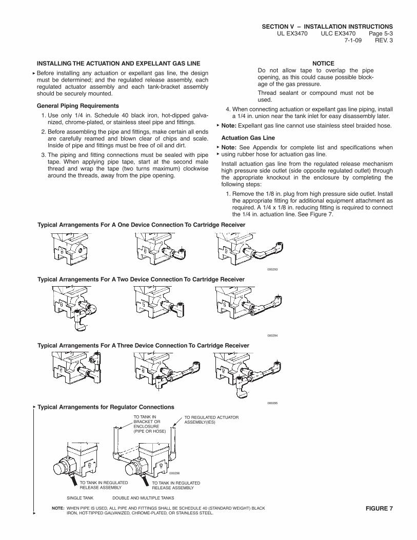
SECTION V – INSTALLATION INSTRUCTIONSUL EX3470 ULC EX3470 Page 5-3
7-1-09 REV. 3
INSTALLING THE ACTUATION AND EXPELLANT GAS LINE
Before installing any actuation or expellant gas line, the designmust be determined; and the regulated release assembly, eachregulated actuator assembly and each tank-bracket assemblyshould be securely mounted.
General Piping Requirements
1. Use only 1/4 in. Schedule 40 black iron, hot-dipped galva-nized, chrome-plated, or stainless steel pipe and fittings.
2. Before assembling the pipe and fittings, make certain all endsare carefully reamed and blown clear of chips and scale.Inside of pipe and fittings must be free of oil and dirt.
3. The piping and fitting connections must be sealed with pipetape. When applying pipe tape, start at the second malethread and wrap the tape (two turns maximum) clockwisearound the threads, away from the pipe opening.
NOTICEDo not allow tape to overlap the pipeopening, as this could cause possible block-age of the gas pressure.
Thread sealant or compound must not beused.
4. When connecting actuation or expellant gas line piping, installa 1/4 in. union near the tank inlet for easy disassembly later.
Note: Expellant gas line cannot use stainless steel braided hose.
Actuation Gas Line
Note: See Appendix for complete list and specifications whenusing rubber hose for actuation gas line.
Install actuation gas line from the regulated release mechanismhigh pressure side outlet (side opposite regulated outlet) throughthe appropriate knockout in the enclosure by completing thefollowing steps:
1. Remove the 1/8 in. plug from high pressure side outlet. Installthe appropriate fitting for additional equipment attachment asrequired. A 1/4 x 1/8 in. reducing fitting is required to connectthe 1/4 in. actuation line. See Figure 7.
FIGURE 7NOTE: WHEN PIPE IS USED, ALL PIPE AND FITTINGS SHALL BE SCHEDULE 40 (STANDARD WEIGHT) BLACKIRON, HOT-TIPPED GALVANIZED, CHROME-PLATED, OR STAINLESS STEEL.
Typical Arrangements For A One Device Connection To Cartridge Receiver
000293
Typical Arrangements For A Two Device Connection To Cartridge Receiver
000294
Typical Arrangements For A Three Device Connection To Cartridge Receiver
000295
000296
TO TANK IN REGULATEDRELEASE ASSEMBLY
SINGLE TANK DOUBLE AND MULTIPLE TANKS
TO TANK IN REGULATEDRELEASE ASSEMBLY
TO TANK INBRACKET ORENCLOSURE(PIPE OR HOSE)
TO REGULATED ACTUATORASSEMBLY(IES)
Typical Arrangements for Regulator Connections

INSTALLING THE ACTUATION AND EXPELLANT GAS LINE(Continued)
Actuation Gas Line (Continued)
2. Run piping or hose up through the regulated release assem-bly enclosure knockout to the inlet on top of each regulatedactuator assembly used within the system.
3. The total combined length of the actuation gas line from theregulated release assembly to all regulated actuator assem-blies must not exceed 20 ft (6 m) when using an LT-20-R nitro-gen cartridge, an LT-30-R nitrogen cartridge, a 101-10 CO2cartridge, or a 101-20 CO2 cartridge. See Figure 8.
Note: When using stainless steel actuation line, a maximumof 17.5 ft (5.3 m) of hose may be used.
4. If an expellant gas line is connected to the regulated releaseassembly along with an actuation gas line, the total combinedlength of the actuation and expellant gas line must notexceed 30 ft (9.1 m). See Figure 9.
5. A combined total of nine fittings may be used in these lines,eight 90° elbows and one tee. Two 45° elbows equal one 90°elbow.
FIGURE 8000775
FIGURE 9000298
SECTION V – INSTALLATION INSTRUCTIONSUL EX3470 ULC EX3470 Page 5-4REV. 5 7-1-09
REGULATED ACTUATORASSEMBLY EXPELLANT GAS LINESNOT INCLUDED IN ACTUATION GASLINE LENGTH TOTALS
REGULATED ACTUATORASSEMBLY
REGULATED ACTUATORASSEMBLY
ANSUL AUTOMANREGULATED RELEASE ASSEMBLY
ACTUATION GAS LINE WITH AN LT-20-R,LT-30-R, 101-20 OR 101-30 CARTRIDGEMAXIMUM LENGTH – 20 FT (6 m),MAXIMUM NO. OF FITTINGS – 9
ACTUATION AND EXPELLANT GAS LINES WITHA “DOUBLE-TANK” OR 101-30 CARTRIDGEMAXIMUM COMBINED LENGTH – 30 FT (9 m),MAXIMUM COMBINED FITTINGS – 9
ANSUL AUTOMAN REGULATEDRELEASE ASSEMBLY
REGULATED RELEASEASSEMBLY
REGULATED ACTUATORASSEMBLY
REGULATED ACTUATORASSEMBLY
REGULATED ACTUATORASSEMBLY EXPELLANTGAS LINES NOT INCLUDEDIN COMBINED TOTALS
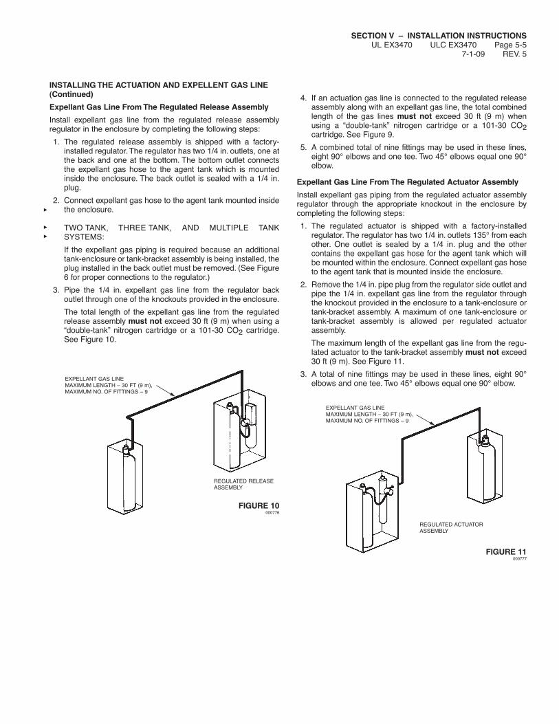
SECTION V – INSTALLATION INSTRUCTIONSUL EX3470 ULC EX3470 Page 5-5
7-1-09 REV. 5
INSTALLING THE ACTUATION AND EXPELLENT GAS LINE(Continued)
Expellant Gas Line From The Regulated Release Assembly
Install expellant gas line from the regulated release assemblyregulator in the enclosure by completing the following steps:
1. The regulated release assembly is shipped with a factory-installed regulator. The regulator has two 1/4 in. outlets, one atthe back and one at the bottom. The bottom outlet connectsthe expellant gas hose to the agent tank which is mountedinside the enclosure. The back outlet is sealed with a 1/4 in.plug.
2. Connect expellant gas hose to the agent tank mounted insidethe enclosure.
TWO TANK, THREE TANK, AND MULTIPLE TANKSYSTEMS:
If the expellant gas piping is required because an additionaltank-enclosure or tank-bracket assembly is being installed, theplug installed in the back outlet must be removed. (See Figure6 for proper connections to the regulator.)
3. Pipe the 1/4 in. expellant gas line from the regulator backoutlet through one of the knockouts provided in the enclosure.
The total length of the expellant gas line from the regulatedrelease assembly must not exceed 30 ft (9 m) when using a“double-tank” nitrogen cartridge or a 101-30 CO2 cartridge.See Figure 10.
FIGURE 10000776
4. If an actuation gas line is connected to the regulated releaseassembly along with an expellant gas line, the total combinedlength of the gas lines must not exceed 30 ft (9 m) whenusing a “double-tank” nitrogen cartridge or a 101-30 CO2cartridge. See Figure 9.
5. A combined total of nine fittings may be used in these lines,eight 90° elbows and one tee. Two 45° elbows equal one 90°elbow.
Expellant Gas Line From The Regulated Actuator Assembly
Install expellant gas piping from the regulated actuator assemblyregulator through the appropriate knockout in the enclosure bycompleting the following steps:
1. The regulated actuator is shipped with a factory-installedregulator. The regulator has two 1/4 in. outlets 135° from eachother. One outlet is sealed by a 1/4 in. plug and the othercontains the expellant gas hose for the agent tank which willbe mounted within the enclosure. Connect expellant gas hoseto the agent tank that is mounted inside the enclosure.
2. Remove the 1/4 in. pipe plug from the regulator side outlet andpipe the 1/4 in. expellant gas line from the regulator throughthe knockout provided in the enclosure to a tank-enclosure ortank-bracket assembly. A maximum of one tank-enclosure ortank-bracket assembly is allowed per regulated actuatorassembly.
The maximum length of the expellant gas line from the regu-lated actuator to the tank-bracket assembly must not exceed30 ft (9 m). See Figure 11.
3. A total of nine fittings may be used in these lines, eight 90°elbows and one tee. Two 45° elbows equal one 90° elbow.
FIGURE 11000777
EXPELLANT GAS LINEMAXIMUM LENGTH – 30 FT (9 m),MAXIMUM NO. OF FITTINGS – 9
REGULATED RELEASEASSEMBLY
EXPELLANT GAS LINEMAXIMUM LENGTH – 30 FT (9 m),MAXIMUM NO. OF FITTINGS – 9
REGULATED ACTUATORASSEMBLY

SECTION V – INSTALLATION INSTRUCTIONSUL EX3470 ULC EX3470 Page 5-6REV. 4 7-1-09
INSTALLING THE ACTUATION AND EXPELLENT GAS LINE(Continued)
Actuation Gas Line From Remote Release(s) to RegulatedActuators
Install actuation gas piping from the remote release(s) to the regu-lated actuators by completing the following:
1. Pipe the 1/4 in. actuation gas line from the 1/4 in. outlet in theremote release receiver, through the knockout provided in thetop of the release enclosure, to each regulated actuatorassembly.
The maximum length of the actuation gas line from the remoterelease to all regulated actuators must not exceed 100 ft.(30.5). See Figure 12. Note: Stainless steel hose and fittingscan be used. See Component Section for detailed information.
2. A maximum of nine tees and twenty elbows are allowed in theactuation piping. Two 45° elbows equal one 90° elbow. SeeFigure 12.
3. A safety relief valve (Part No. 15677) must be installed in theactuation piping. See Figure 12.
Actuation Gas Line – 15* Tanks Maximum – Using 1/4 in.Stainless Steel Hose
Note: Not for use with expellent gas line.
1. Maximum hose length cannot exceed 17.5 ft (5.3 m). SeeFigure 13.
2. Maximum of 5 regulated actuators allowed.
3. Actuated with Remote Release (Part No. 433485) orRegulated Release Assembly (Part No. 429853).
FIGURE 12000301
SAFETY RELIEFVALVE
EXPELLANTGAS LINE
1/4 IN. ACTUATION LINE – 100 FT (30.5 m) MAXIMUM
REGULATEDACTUATORWITH TANK (TYP.)
AGENT TANK AND BRACKET ORAGENT TANK IN ENCLOSURE (TYP.)
9 TEESMAXIMUM
20 ELBOWSMAXIMUM
CHECKVALVE
REMOTE RELEASEMECHANISMS ORREGULATEDRELEASES (5 MAXIMUM)
1/4 IN. STAINLESSSTEEL HOSE
MAXIMUM OF 5REGULATED ACTUATORS
REGULATED ACTUATORWITH TANK
NOTE: WHEN MULTIPLE RELEASE ASSEMBLIES ARE UTILIZED, A 1/4 IN. CHECK VALVE, PART NO. 25627,WILL BE REQUIRED AFTER EACH REGULATED RELEASE.
NOTE: *15 TANKS MAXIMUM REFLECTS THE UTILIZATION OF THREE (3) TANK REGULATED ACTUATORS.
1/4 IN. STAINLESS STEEL HOSE OPTIONS
SAFETYRELIEF VALVE
MAXIMUM OF 5REMOTERELEASEMECHANISMS(PART NO.433485) ORONE (1)REGULATEDRELEASE (PARTNO. 429853)
CHECK VALVE
FIGURE 13000301
42 IN. (107 cm)MAX. HOSE
LENGTH (TYP.)

SECTION V – INSTALLATION INSTRUCTIONSUL EX3470 ULC EX3470 Page 5-7
7-1-09 REV. 6
INSTALLING THE DISTRIBUTION PIPING
Before the following procedures can be completed, the pipingdesign must already be determined; and the actuation and expel-lant gas lines from the regulated release, each regulated actuator,and each tank-enclosure or tank-bracket assembly should alreadybe installed.
These installation instructions are identical for single, double, andmultiple-tank systems except for the quantity of tanks and hazardareas to be covered.
General Piping Requirements
1. Use Schedule 40 black iron, chrome-plated, or stainless steelpipe and fittings.
NOTICEDo not use hot-dipped galvanized iron pipe orfittings in the agent distribution piping.
2. Before assembling the pipe and fittings, make certain all endsare carefully reamed and blown clear of chips and scale.Inside of pipe and fittings must be free of oil and dirt.
3. The distribution piping and fitting connections, located in orabove the hood or the protected area, must be sealed withpipe tape. When applying pipe tape, start at the second malethread and wrap the tape (two turns maximum) clockwisearound the threads, away from the pipe opening.
NOTICEDo not allow tape to overlap the pipe opening asthe pipe and nozzles could become plugged.Thread sealant or compound must not be usedas it could plug the nozzles.
4. Distribution piping may be run independently or two agenttanks may be manifolded together and run to the predeter-mined hazard area. Only agent tanks expelled from the samecartridge may be manifolded.
NOTICEClosely follow the piping requirements for eachsize system, as detailed in the “System Design”section, when installing distribution piping.
5. Branchline tees can be used to create more than one branchand can be installed as a thru tee, side outlet tee or bull tee.
Pipe Hanger Recommended Guidelines
1. Space hangers as follows:
Maximum RecommendedPipe Size Distance Between Hangers________ ______________________3/8 in. 5 ft (1.5 m)
2. Hangers should be placed between elbows when the distanceis greater than 2 ft (0.6 m).
Piping Installation
1. Starting at the tank, pipe directly from the union located on thetank adaptor. A reducing fitting may be necessary to conformto the distribution piping.
2. Based on the piping sketch developed in the “System Design”section of this manual, install the supply line and position thetees at points where branch lines must be installed. SeeFigure 14.
3. Run all branch lines to the hazard area and connect eachnozzle. (Make certain all piping is securely bracketed.)
FIGURE 14000302
4. Make certain all threaded connections are properly tightened.Threaded connections located in the protected area(s) andabove the hood must be sealed with Teflon pipe tape, as aminimum. Apply pipe tape to male threads only. Make certaintape does not extend over the end of the thread, as this couldcause possible blockage of the agent distribution.
Pipe tape minimizes friction between bearing surfaces of thethreads when threading pipe to fittings.The resulting heat mayexpand the pipe threads before the joint is properly made.When the pipe threads cool and contract in the fitting, the jointmay become loosened causing cooking grease to migrate intothe distribution piping, and/or leakage at the fitting during apressure test or agent discharge.
Note: When required to provide pressure testing of pipe or asystem discharge test, it is recommended that all pipe connec-tions utilize Teflon pipe tape.
5. Install the correct nozzle(s) for each hazard area as previouslydesigned. Some nozzles are required to be properly orientedbefore they are positioned for aiming.
6. Aim the nozzles to a pre-determined aim point in accordancewith the instructions in the “System Design” section. Using theNozzle Aiming Device (Part No. 431992) will aid in the aimingprocess. The device clamps to the nozzle and emits a smalllaser light that reflects on the surface where it is aiming. If thenozzle is used with Swivel Adapter (Part No. 418569), thenozzle with Aiming Device can be rotated to the exact aimingpoint and then tightened to hold that angle.
7. Before installing blow-off caps on nozzles, apply a smallamount of Dow Corning No. 111 silicone grease across theopening in the nozzle tip and also a small amount coating theexterior of the blow-off cap. DO NOT FORCE SILICONEGREASE INTO NOZZLE TIP OPENING OR FILL CAP WITHGREASE.
NOTICEWhen using old style metal blow-off cap, makecertain the spring clip rotates freely on the metalcap and coat the outside of the cap, including theclip, with Dow Corning No. 111 silicone grease.
8. Make certain a blow-off cap is in place over each nozzle tip.These blow-off caps are designed to keep grease from build-ing-up on the nozzle orifice and inhibiting the agent flow. SeeFigure 15.
000303 000304 000305
FIGURE 15

SECTION V – INSTALLATION INSTRUCTIONSUL EX3470 ULC EX3470 Page 5-7.1REV. 0 7-1-09
INSTALLING THE AGENT DISTRIBUTION HOSE(FOR CASTERED/MOVEABLE EQUIPMENT)Agent Distribution Hose can be used in the supply line or appliancebranch line to allow a castered cooking appliance with casteredsupports with nozzles attached directly to the appliance, to bemoved out of its normal operating position for service or cleaning.
CRITICAL INSTALLATION REQUIREMENTS
1. Design and installation must be performed by qualifiedpersonnel.
2. The Agent Distribution Hose shall not be concealed within orrun through any wall, floor, or partition, and shall not have anydirect exposure to excessive heat or radiant flame from thecooking appliances.
3. Strong cleaning solutions or chemical substances must notcome in contact with the Agent Distribution Hose. These mayinclude acids, solvents, fluxes with zinc chloride, or other chlo-rinated chemicals. In case of contact, rinse down the AgentDistribution Hose with water and dry thoroughly.
4. Contact with foreign objects, sharp edges, wiring, orsubstances must be avoided.
5. Bending and flexing of Agent Distribution Hose on moveableappliances (i.e. those factory equipped with casters) shouldbe limited to pulling and pushing the appliances in or out forcleaning or maintenance. The hose shall never be installed orbent tighter than a 3 in. (7.6 cm) radius (6 in. (15.2 cm) diam-eter) loop.
6. The Agent Distribution Hose must not be kinked, twisted, orhave sharp bends when installed or when equipment is pulledaway from the wall.
7. Make sure that all fittings are tightened properly.
8. Adequate means must be provided to limit the movement ofcastered appliances. A 36 in. (91.4 cm) long RestrainingCable supplied with the agent distribution hose is required tobe used for all castered appliances using the AgentDistribution Hose. (Refer to Restraining Cable InstallationInstructions.)
9. The Restraining Cable requires periodic maintenance toensure proper operation.
10. The Restraining Cable must be attached to the wall and appli-ance anytime the distribution hose is connected to the appli-ance.
11. Do not over-extend the Agent Distribution Hose when movingequipment (for cleaning, maintenance, etc.).
AGENT DISTRIBUTION HOSE INSTALLATION INSTRUCTIONSBefore proceeding, CAREFULLY read all instructions, including allCRITICAL INSTALLATION REQUIREMENTS.
General Requirements1. The Agent Distribution Hose, Part No. 434462 (which is part
of Discharge Hose and Restraining Cable Kit, Part No.435982), is 1/2 in. (12.7 mm) diameter x 60 in. (152.4 cm) longand is provided with two (2) male NPT swivels for ease ofinstallation.
2. Maximum of six (6) Agent Distribution Hoses can be used ineach agent distribution piping network.
3. Agent Distribution Hose can only be used for castered appli-ances or appliances setting on castered supports.
4. Maximum of two (2) Agent Distribution Hoses are allowed inthe supply line. However, the Agent Distribution Hose can onlybe used at the castered appliance.
5. Maximum of two (2) Agent Distribution Hoses are allowed inthe branch line. An acceptable installation scenario would beproviding separate protection of two (2) (side-by-side) appli-ances, each with its own Agent Distribution Hose and tether,supplied from the same appliance branch.
6. The Agent Distribution Hose is to only be used in the distrib-ution piping of a single 1 1/2 or 3 gal (5.7 or 11.4 L) tank ortwo (2) manifolded 3 gal (11.4 L) R-102 extinguishing systemsor larger systems using combinations thereof. However, theAgent Distribution Hose is never to be used to manifold two(2) 3 gal (11.4 L) tanks.
Installation Requirements
1. Agent Distribution Hose must be connected to 3/8 in. NPTblack iron, chrome-plated, or stainless steel fittings. Theconnection from hose to fitting requires a 1/2 in. x 3/8 in.reducing coupling, Ansul Part No. 436228. All AgentDistribution Hose connections must be sealed with pipe tape.When applying pipe tape, start at the second male thread onthe swivel ends of the hose. Wrap the tape (two turnsmaximum) clockwise around the threads, away from the hoseend fitting opening.
2. All connections of distribution piping to Agent DistributionHose for castered appliances, with distribution nozzlesinstalled/affixed to the appliance, must be located behind thecooking equipment in an area protected from obstructionsand possible wear or damage.
3. 3/8 in. schedule 40 pipe will need to be run from the hoseconnection to the distribution nozzle(s) installed/affixed to theappliance. Pipe must be installed and adequately secured ata height at or below the cooking surface of the appliance. (SeeFigure 21.)
4. All existing distribution pipe and fitting limitations must beobserved and followed. Each flex distribution hose used is tobe considered as an equivalent length of 3/8 in. pipe whencalculating the acceptable length (ft (m)) of allowable distribu-tion pipe.
5. All hose-to-pipe connection fittings are to be oriented in avertical down position.
6. The hose connections must be positioned below an elevationwhere the hose could be exposed to the radiant or convectedheat generated by normal cooking operations (such as thehorizontal plane of appliance’s cooking surface), or to heatfrom appliance exhaust. As a minimum height, the hoseconnection shall be no lower than 30 in. (76.2 cm) from thefloor. The distribution piping shall be supported and securedper local plumbing practices.
7. Hose ends are to be offset 6 to 8 in. (15.2 to 20.3 cm) centerto center of fittings (See Figure 16) to maximize hose lifeexpectancy and facilitate appliance movement. With the appli-ance in its normal operating position, check the hose bend tomake certain the bend is not less than a 3 in. (7.6 cm) bendradius (6 in. (15.2 cm) diameter).
WARNING!
The following instructions must be followed in their entirety.Failure to do so may result in the R-102 Fire SuppressionSystem not functioning properly due to incorrect installation.

SECTION V – INSTALLATION INSTRUCTIONSUL EX3470 ULC EX3470 Page 5-7.2
7-1-09 REV. 0
AGENT DISTRIBUTION HOSE INSTALLATION INSTRUCTIONS(Continued)
Installation Requirements (Continued)
FIGURE 16007828
Restraining Cable Installation
Important: A Restraining Cable shall always be permanentlyattached to the appliance and wall directly behind the appliancewhen the Agent Distribution Hose is installed. Removal of thiscable shall only occur when the Agent Distribution Hose is notinstalled to the appliance.
See Figure 17 for mounting the Restraining Cable to the wall. SeeFigure 18 for mounting the Restraining Cable to the back of anappliance.
FIGURE 17008088
FIGURE 18008089
FIGURE 19008090
1. The Restraining Cable must be connected from the applianceto the wall or some other structurally sound object capable ofrestraining the castered appliance from being able to bepulled or pushed out to a point that will result in strain or stressto the Agent Distribution Hose.
2. The Restraining Cable should be installed in line with theAgent Distribution Hose.
3. For sheet metal covered walls, the Restraining CableAssembly includes four (4) 3/4 in. x #8 self tapping sheetmetal screws, and a Restraining Cable Bracket. Securelyattach the Restraining Cable Bracket to the sheet metalcovered wall using the 3/4 in. x #8 self tapping metal screwsprovided.
4. For mounting to wall studs, the Restraining Cable Assemblyincludes one (1) screw eye lag bolt, 5/16 in. x 2.5 in. (6.4 cm)long.
5. Locate a structural area (frame) on the rear side of the equip-ment that is in line with the wall attachment. Note: It may benecessary to contact the appliance manufacturer for a suit-able location. Drill a 5/16 in. (8 mm) diameter hole. Usecaution when drilling hole, so that internal components are notdamaged.
6. The Restraining Cable Assembly also includes a 5/16 in.threaded eye-bolt, 5/16 in. hex head nut, 5/16 in nylon locknut, and two (2) 5/16 in. flat washers. Thread the included hexnut onto the eye-bolt. Slide one washer onto the eye-boltthreads next to the nut. Then, slide the eye-bolt through thedrilled hole and place a washer and nylon locknut onto theeye-bolt on the inside frame of the equipment. Tightensecurely.
(4) SELF TAPPINGSHEET METALSCREWS
WALLSTUD
SHEET METALCOVERED WALLS
WALLMOUNTBRACKET
SCREWEYE BOLT
RESTRAINING CABLE – WALL-MOUNTED OPTION
BACK OFAPPLIANCE
NYLONLOCK NUT
WASHERWASHER
NUT
EYEBOLT
RESTRAINING CABLE – APPLIANCE-MOUNTED OPTION
WASHER
BACK OFAPPLIANCE
EYENUT
PHILIPSSCREW
RESTRAINING CABLE – HENNY PENNY-MOUNTED OPTION
6-8 IN (15.2-20.3 cm) OFFSETCENTER TO CENTER PIPE (SUPPLIED ONLY WITH
HENNY PENNY FRYER NOZZLE KIT,PART NO. 434455)
PIPE (NOTSUPPLIED INKIT)
FLEXHOSE
TETHER
OVERHEAD VIEW
APPLIANCEWALL

SECTION V – INSTALLATION INSTRUCTIONSUL EX3470 ULC EX3470 Page 5-7.3REV. 0 7-1-09
AGENT DISTRIBUTION HOSE INSTALLATION INSTRUCTIONS(Continued)
Restraining Cable Installation (Continued)
7. Attach one of the snap hooks (included in the RestrainingCable package) on the end of the Restraining Cable to thewall bracket and the other snap hook to the eye-bolt (SeeFigure 20). After snap-hooking the assembly, seal theRestraining Cable Loops to the wall bracketry and applianceconnection hardware with ANSUL Lead Wire Seal, Part No.197.
Note: For the Henny Penny Pressure Fryers that utilize theANSUL Henny Penny Fryer Nozzle Kit, Part No. 434455, the5/16 in. philips screw supplied in the Henny Penny FryerNozzle Kit, the 5/16 in. eye nut, and 5/16 in. washer includedin the Restraining Cable Assembly Kit, must be used. (SeeFigure 19).
FIGURE 20007829
Final Installation Guidelines and Checkout Procedures
After the Agent Distribution Hose and the Restraining Cable isproperly installed, carefully push the appliance back to its normaloperating position. Check that the hose does not have sharpbends, and is not kinked, twisted, or caught on anything behind theappliance.
1. Verify the Restraining Cable limits the travel of the applianceand prevents the application of any pull force or bendingstress on the Agent Distribution Hose or hose-to-pipe connec-tions.
2. Make certain there are no sharp bends and kinks in the hosewhen pulling out the cooking equipment.
3. The Agent Distribution Hose should always be in a verticalnatural loop, never having any bends greater than a 3 in.(7.6 cm) radius (6 in. (15.2 cm) diameter), hose twists, orsharp bends. (See Figure 21.) If any of these conditions exist,the hose and/or hose connections will require installationmodifications.
FIGURE 21007830
4. Return the appliance to its normal operating position in accor-dance with NFPA 96. Means shall be provided to verify thatthe appliance returns to its original designed positioning.Failure to do so may result in undue stress and fatigue of thehose and hose connections.
ACCEPTABLE HOSE ORIENTATION
UNACCEPTABLE HOSE ORIENTATION
MAXIMUMHEIGHT OF
HOSECONNECTION ISTO BE BELOW
THE APPLIANCECOOKINGSURFACE
AGENTDISTRIBUTION
3/8 INPIPING
WALL
SHARP BENDS TWISTING FATIGUE
SIDE VIEW
RESTRAINING CABLEINSTALLATION PACKAGE
E – 5/16 IN HEX NUT
A – RESTRAINING CABLE
F – 5/16 IN NYLONLOCK NUT
G – 5/16 INX 5/16 INWASHERS(2)
B – STAPLEBRACKET
C – 3/4 IN. X #8SCREWS (4)
H – SCREWEYE BOLT
I – SNAPHOOK
D – EYE BOLT
B – STAPLE BRACKET
D – EYE BOLT
I – SNAP HOOK
I – SNAPHOOK
EYE BOLT FASTENINGHARDWARE
A – RESTRAININGCABLE
MIN.30 IN(76.2cm)

SECTION V – INSTALLATION INSTRUCTIONSUL EX3470 ULC EX3470 Page 5-7.4
7-1-09 REV. 0
NOTES:

SECTION V – INSTALLATION INSTRUCTIONSUL EX3470 ULC EX3470 Page 5-8REV. 3 7-1-09
INSTALLING THE DETECTION SYSTEM
Before the following procedures can be completed, the detectiondesign must already be completed. These installation instructionsare identical for single, double, and multiple-tank systems exceptfor the number of hazard areas to be covered.
NOTICEInform customer that fusible links should not beexposed to ammonia-based chemical cleanersor steam.
1. Based on the requirements listed in the “System Design”section, mount the detectors in their predetermined locations.
2. Run 1/2 in. conduit from the regulated release mechanism triphammer assembly knockout hole to locations selected formounting the detectors.
Note: Before assembling the conduit and fittings, makecertain all ends are carefully reamed and blown clear of chipsand scale. Inside of pipe and fittings must be free of oil anddirt.
When changing the direction of conduit, use only ANSULpulley elbows, except, at the top of the regulated release, it isacceptable to use the “Conduit Offset Assembly” (Part No.436063).
Note: If stainless steel scissor linkage is used in the systemwhile using conduit off-set assembly, the following limitationsmust be observed:• Maximum number of elbows – 16• Maximum number of detectors – 15• Maximum length of 1/2 in. EMT Conduit – 150 ft (45.7 m)
Part No. 435546 and 435547 are the “scissor” style series andterminal detector assemblies. These detector assemblies usea detector linkage assembly which does not require the wirerope to be threaded through the linkage assembly while it isbeing fed through the detection system.
“Scissor” Style Linkage Installation
1. Secure the conduit to the detector bracket using the two1/2 in. steel compression fittings on the series detector bracketor the single 1/2 in. steel compression fitting on the terminaldetector bracket. See Figure 22.
FIGURE 22000306
NOTICEDo not use zinc die cast compression connec-tors on the detection conduit lines as these willnot withstand the normally high temperaturesexperienced in the plenum area.
2. For a terminal detector located in a duct or header opening,secure both sides of the detector bracket with conduit, asshown in Figure 23.
002463
002464
FIGURE 23
COMPRESSIONFITTING NUT
1/2 IN. STEELCOMPRESSION FITTING

SECTION V – INSTALLATION INSTRUCTIONSUL EX3470 ULC EX3470 Page 5-9
7-1-09 REV. 2
INSTALLING THE DETECTION SYSTEM (Continued)
“Scissor” Style Linkage Installation (Continued)
3. Starting at the release assembly, feed the wire rope throughthe hole in the release mechanism locking clamp, allowing theexcess wire rope to hang down. (Do not tighten set screws inlocking clamp at this time.) See Figure 24.
FIGURE 24000309
4. From the release assembly, run the stainless steel wire ropethrough the conduit, pulley elbows and detector brackets tothe terminal detector.
NOTICEIf wire rope requires splicing, make certainsplice is at least 12 in. (30.5 cm) away from anypulley elbow or conduit adaptor to avoid interfer-ence.
5. Feed the wire rope through the terminal detector bracket asshown in Figure 25 or as shown in Figure 26 if the terminaldetector is mounted within a duct or header opening, andinstall the stop sleeve approximately 2 to 3 in. (5 to 8 cm) fromthe end of the wire rope. See Figure 27. Use the NationalTelephone Supply Company Nicopress Sleeve Tool (Stock No.51-C-887) or equal to properly crimp the stop sleeve.
FIGURE 25000310
FIGURE 26000311
FIGURE 27000312
6. To give a constant tension on the wire rope during installationof the detector linkage, hang a vice grip or other weighteddevice on the excess stainless steel wire rope, leaving anadequate length of spare wire rope between the locking clampand the weighted device.
NOTICEWhen attaching the weighted device to theexcess wire rope, allow approximately 3 in.(8 cm) of wire rope for each detector linkage forproper installation.
Example: If the system has six detectors, there should beapproximately 18 in. (46 cm) of excess wire ropebetween the locking clamp and the weighteddevice, which will be utilized when the linkage isput in place.
7. Install detector scissor assembly as shown in Figure 28. Notethat the ANSUL AUTOMAN or remote release assembly islocated on the left side of the detector bracket. Slightly crimpthe two assembly “boot-hooks” over the cable with pliers sothe cable is captured under each hook but the whole assem-bly can move from side to side. Center the assembly in thedetector bracket.
FIGURE 28000503
LOCKINGCLAMP
2-3 IN.(5-8 cm)
“ANSUL AUTOMAN” ORREMOTE RELEASE ASSEMBLY

SECTION V – INSTALLATION INSTRUCTIONSUL EX3470 ULC EX3470 Page 5-10REV. 3 7-1-09
INSTALLING THE DETECTION SYSTEM (Continued)
“Scissor” Style Linkage Installation (Continued)
8. Hook the fusible link on the ANSUL AUTOMAN or remoterelease assembly side of the hook assembly, then pull thefusible link to the opposite side and complete the hookup asshown in Figures 29 and 30. The top of the hook assemblymust be inside the bracket stiffeners. The hook assembly withthe ANSUL fusible link in place must be located toward theterminal detector side of the bracket.
FIGURE 29000504
FIGURE 30000324
9. Install the linkage and the correct ANSUL approved fusible linkin the remainder of the detector brackets. Make certain alldetector linkages are positioned against either the front orback upper lip of the formed detector bracket. See Figure 30a.
FIGURE 30a004429
10. Insert cocking lever (Part No. 14995 or Part No. 435603) onleft side of the release mechanism, with the movable flangeresting securely against the corner of the cartridge receiverand spring housing, and with the notched lever portion engag-ing the cocking pin on both sides of the release mechanism.See Figure 31.
FIGURE 31000319
11. Using long handle cocking lever, Part No. 14995, or wrench onshort handle cocking lever nut, Part No. 435603, pull down toraise cocking pin until the trip lever indented surface movesunderneath the pin and locks the pin in the up position. SeeFigure 32.
FIGURE 32000320
COCKING LEVER
COCKING PIN

SECTION V – INSTALLATION INSTRUCTIONSUL EX3470 ULC EX3470 Page 5-11
7-1-09 REV. 3
INSTALLING THE DETECTION SYSTEM (Continued)
“Scissor” Style Linkage Installation (Continued)
12. Remove cocking lever and insert lock bar (Part No. 14985) onleft side of the cable lever, over the two shouldered projectingstud extensions, and slide bar forward into locking position.(The release mechanism cannot be actuated, nor can enclo-sure cover be replaced until the lock bar is removed.) SeeFigure 33.
FIGURE 33000321
13. Make certain tension lever is in the “UP” position. SeeFigure 34.
TENSION LEVERIN “UP” POSITION
FIGURE 34000322
14. Verify each detector linkage assembly, with correct fusible link,is in the detector bracket, located fully toward the terminaldetector side.
NOTICEDue to the close adjustment between the triphammer and cable lever assemblies, use onlythe particular fusible link(s) selected for installa-tion in each detector, including terminal detec-tor, to ensure correct adjustment whenperforming Steps 15 and 16.
15. Raise trip hammer 3/8 in. to 1/2 in. (9.5 to 12.7 mm), pull allslack out of wire rope, and tighten set screws on lockingclamp.
16. Lower tension lever to “DOWN” position and inspect the baseof the wire rope locking clamp to make certain that there is aminimum of 1/4 in. (6.4 mm) and a maximum of 3/8 in.(9.5 mm) clearance between the base of the trip hammerlocking clamp assembly and the cable lever assembly. SeeFigure 35. (If clearance is not between 1/4 in. (6.4 mm) or 3/8in. (9.5 mm), raise tension lever, loosen set screws on lockingclamp and repeat Steps 15 and 16.)
FIGURE 35000323
17. Test detection system in accordance with the Testing andPlacing in Service Section, Page 7-1 – 7-3, of this manual.
18. When testing has been completed, cut off excess wire rope inthe regulated release assembly, leaving approximately 2 in.(5.1 cm) of wire rope below the locking clamp.
LOCK BARPROPERLY INSTALLED
CAUTION!
Do not install cartridge at this time as an accidental actu-ation could cause system discharge.
CAUTION!
Make certain the hook assembly with the ANSUL fusiblelink in place is located toward the terminal detector side ofeach bracket. Failure to do so may restrict travel of detec-tion line, causing system to malfunction.
TRIP HAMMERASSEMBLY
1/4 IN. MINIMUM(6.4 mm)
3/8 in. MAXIMUM(9.5 mm)
CABLELEVERASSEMBLY
LOCKINGCLAMP
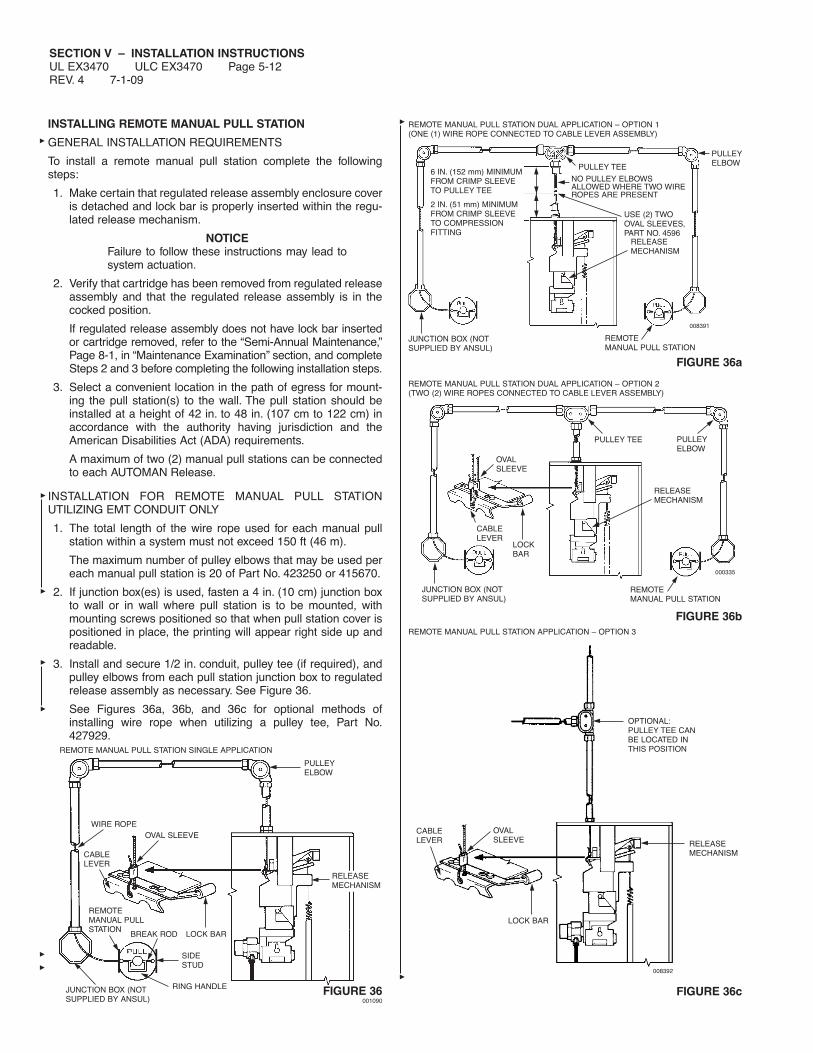
SECTION V – INSTALLATION INSTRUCTIONSUL EX3470 ULC EX3470 Page 5-12REV. 4 7-1-09
INSTALLING REMOTE MANUAL PULL STATION
GENERAL INSTALLATION REQUIREMENTS
To install a remote manual pull station complete the followingsteps:
1. Make certain that regulated release assembly enclosure coveris detached and lock bar is properly inserted within the regu-lated release mechanism.
NOTICEFailure to follow these instructions may lead tosystem actuation.
2. Verify that cartridge has been removed from regulated releaseassembly and that the regulated release assembly is in thecocked position.
If regulated release assembly does not have lock bar insertedor cartridge removed, refer to the “Semi-Annual Maintenance,”Page 8-1, in “Maintenance Examination” section, and completeSteps 2 and 3 before completing the following installation steps.
3. Select a convenient location in the path of egress for mount-ing the pull station(s) to the wall. The pull station should beinstalled at a height of 42 in. to 48 in. (107 cm to 122 cm) inaccordance with the authority having jurisdiction and theAmerican Disabilities Act (ADA) requirements.
A maximum of two (2) manual pull stations can be connectedto each AUTOMAN Release.
INSTALLATION FOR REMOTE MANUAL PULL STATIONUTILIZING EMT CONDUIT ONLY
1. The total length of the wire rope used for each manual pullstation within a system must not exceed 150 ft (46 m).
The maximum number of pulley elbows that may be used pereach manual pull station is 20 of Part No. 423250 or 415670.
2. If junction box(es) is used, fasten a 4 in. (10 cm) junction boxto wall or in wall where pull station is to be mounted, withmounting screws positioned so that when pull station cover ispositioned in place, the printing will appear right side up andreadable.
3. Install and secure 1/2 in. conduit, pulley tee (if required), andpulley elbows from each pull station junction box to regulatedrelease assembly as necessary. See Figure 36.
See Figures 36a, 36b, and 36c for optional methods ofinstalling wire rope when utilizing a pulley tee, Part No.427929.
FIGURE 36001090
FIGURE 36a
FIGURE 36b
FIGURE 36c
REMOTE MANUAL PULL STATION SINGLE APPLICATION
REMOTE MANUAL PULL STATION DUAL APPLICATION – OPTION 1(ONE (1) WIRE ROPE CONNECTED TO CABLE LEVER ASSEMBLY)
RELEASEMECHANISM
PULLEYELBOW
WIRE ROPE
CABLELEVER
OVAL SLEEVE
REMOTEMANUAL PULLSTATION
BREAK ROD LOCK BAR
SIDESTUD
JUNCTION BOX (NOTSUPPLIED BY ANSUL)
RING HANDLE
JUNCTION BOX (NOTSUPPLIED BY ANSUL)
PULLEY TEE
NO PULLEY ELBOWSALLOWED WHERE TWO WIREROPES ARE PRESENT
USE (2) TWOOVAL SLEEVES,PART NO. 4596
PULLEYELBOW
RELEASEMECHANISM
REMOTEMANUAL PULL STATION
008392
RELEASEMECHANISM
OVALSLEEVE
LOCK BAR
CABLELEVER
OPTIONAL:PULLEY TEE CANBE LOCATED INTHIS POSITION
008391
REMOTE MANUAL PULL STATION DUAL APPLICATION – OPTION 2(TWO (2) WIRE ROPES CONNECTED TO CABLE LEVER ASSEMBLY)
REMOTE MANUAL PULL STATION APPLICATION – OPTION 3
OVALSLEEVE
CABLELEVER
LOCKBAR
JUNCTION BOX (NOTSUPPLIED BY ANSUL)
PULLEY TEE PULLEYELBOW
RELEASEMECHANISM
REMOTEMANUAL PULL STATION
000335
6 IN. (152 mm) MINIMUMFROM CRIMP SLEEVETO PULLEY TEE
2 IN. (51 mm) MINIMUMFROM CRIMP SLEEVETO COMPRESSIONFITTING
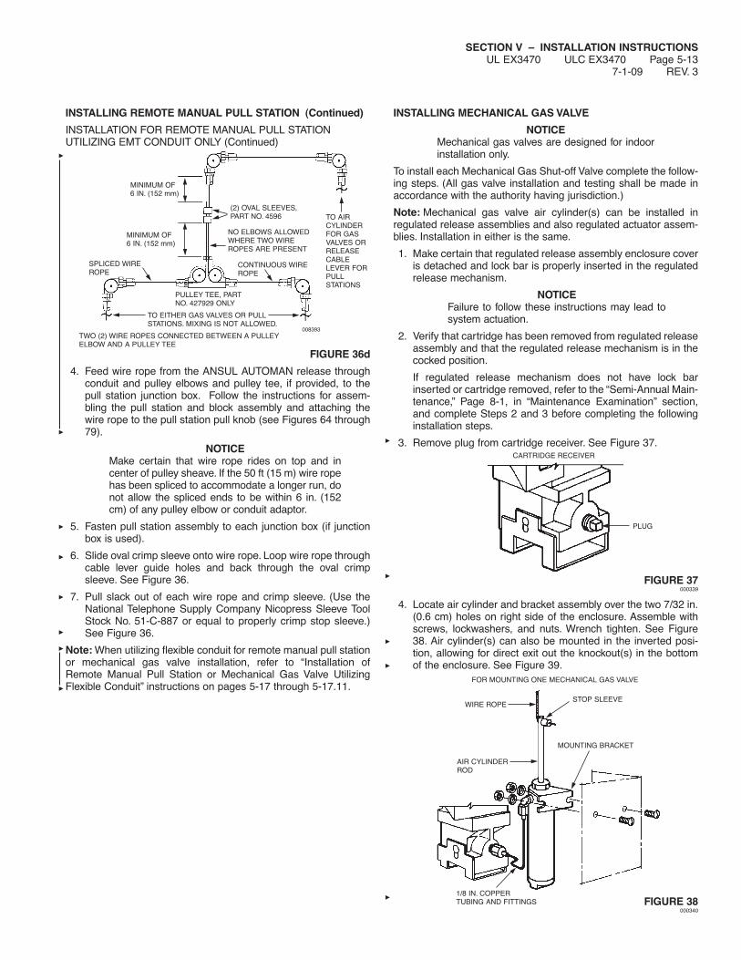
SECTION V – INSTALLATION INSTRUCTIONSUL EX3470 ULC EX3470 Page 5-13
7-1-09 REV. 3
INSTALLING REMOTE MANUAL PULL STATION (Continued)
INSTALLATION FOR REMOTE MANUAL PULL STATIONUTILIZING EMT CONDUIT ONLY (Continued)
FIGURE 36d
4. Feed wire rope from the ANSUL AUTOMAN release throughconduit and pulley elbows and pulley tee, if provided, to thepull station junction box. Follow the instructions for assem-bling the pull station and block assembly and attaching thewire rope to the pull station pull knob (see Figures 64 through79).
NOTICEMake certain that wire rope rides on top and incenter of pulley sheave. If the 50 ft (15 m) wire ropehas been spliced to accommodate a longer run, donot allow the spliced ends to be within 6 in. (152cm) of any pulley elbow or conduit adaptor.
5. Fasten pull station assembly to each junction box (if junctionbox is used).
6. Slide oval crimp sleeve onto wire rope. Loop wire rope throughcable lever guide holes and back through the oval crimpsleeve. See Figure 36.
7. Pull slack out of each wire rope and crimp sleeve. (Use theNational Telephone Supply Company Nicopress Sleeve ToolStock No. 51-C-887 or equal to properly crimp stop sleeve.)See Figure 36.
Note: When utilizing flexible conduit for remote manual pull stationor mechanical gas valve installation, refer to “Installation ofRemote Manual Pull Station or Mechanical Gas Valve UtilizingFlexible Conduit” instructions on pages 5-17 through 5-17.11.
INSTALLING MECHANICAL GAS VALVE
NOTICEMechanical gas valves are designed for indoorinstallation only.
To install each Mechanical Gas Shut-off Valve complete the follow-ing steps. (All gas valve installation and testing shall be made inaccordance with the authority having jurisdiction.)
Note: Mechanical gas valve air cylinder(s) can be installed inregulated release assemblies and also regulated actuator assem-blies. Installation in either is the same.
1. Make certain that regulated release assembly enclosure coveris detached and lock bar is properly inserted in the regulatedrelease mechanism.
NOTICEFailure to follow these instructions may lead tosystem actuation.
2. Verify that cartridge has been removed from regulated releaseassembly and that the regulated release mechanism is in thecocked position.
If regulated release mechanism does not have lock barinserted or cartridge removed, refer to the “Semi-Annual Main-tenance,” Page 8-1, in “Maintenance Examination” section,and complete Steps 2 and 3 before completing the followinginstallation steps.
3. Remove plug from cartridge receiver. See Figure 37.
FIGURE 37000339
4. Locate air cylinder and bracket assembly over the two 7/32 in.(0.6 cm) holes on right side of the enclosure. Assemble withscrews, lockwashers, and nuts. Wrench tighten. See Figure38. Air cylinder(s) can also be mounted in the inverted posi-tion, allowing for direct exit out the knockout(s) in the bottomof the enclosure. See Figure 39.
FIGURE 38000340
TO AIRCYLINDERFOR GASVALVES ORRELEASECABLELEVER FORPULLSTATIONS
NO ELBOWS ALLOWEDWHERE TWO WIREROPES ARE PRESENT
(2) OVAL SLEEVES,PART NO. 4596
PULLEY TEE, PARTNO. 427929 ONLY
TO EITHER GAS VALVES OR PULLSTATIONS. MIXING IS NOT ALLOWED.
TWO (2) WIRE ROPES CONNECTED BETWEEN A PULLEYELBOW AND A PULLEY TEE
SPLICED WIREROPE
CONTINUOUS WIREROPE
MINIMUM OF6 IN. (152 mm)
MINIMUM OF6 IN. (152 mm)
008393
CARTRIDGE RECEIVER
PLUG
FOR MOUNTING ONE MECHANICAL GAS VALVE
WIRE ROPESTOP SLEEVE
AIR CYLINDERROD
MOUNTING BRACKET
1/8 IN. COPPERTUBING AND FITTINGS
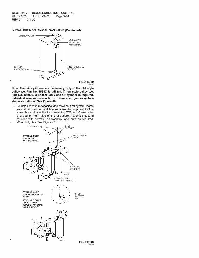
SECTION V – INSTALLATION INSTRUCTIONSUL EX3470 ULC EX3470 Page 5-14REV. 3 7-1-09
INSTALLING MECHANICAL GAS VALVE (Continued)
FIGURE 39000341
Note: Two air cylinders are necessary only if the old stylepulley tee, Part No. 15342, is utilized. If new style pulley tee,Part No. 427929, is utilized, only one air cylinder is required.Individual wire ropes can be run from each gas valve to asingle air cylinder. See Figure 40.
5. To install second mechanical gas valve shut-off system, locatesecond air cylinder and bracket assembly adjacent to firstassembly and over the two remaining 7/32 in. (.6 cm) holesprovided on right side of the enclosure. Assemble secondcylinder with screws, lockwashers, and nuts as required.Wrench tighten. See Figure 40.
FIGURE 40000342
WIRE ROPE STOPSLEEVES
AIR CYLINDERRODS
MOUNTINGBRACKETS
1/8 IN. COPPERTUBING AND FITTINGS
004655
000342
(SYSTEMS USINGPULLEY TEE, PART NO.427929)
NOTE: NO ELBOWSARE ALLOWEDBETWEEN AUTOMANAND PULLEY TEE
(SYSTEMS USINGPULLEY TEE,PART NO. 15342)
STOPSLEEVES(2)
TOP KNOCKOUTS
BOTTOMKNOCKOUTS
MECHANICALGAS VALVEAIR CYLINDER
R-102 REGULATEDRELEASE

SECTION V – INSTALLATION INSTRUCTIONSUL EX3470 ULC EX3470 Page 5-15
7-1-09 REV. 4
INSTALLING MECHANICAL GAS VALVE (Continued)
6. Install the necessary 1/8 in. copper tubing and fittings for eachair cylinder to the accessories piping arrangement on theregulated release mechanism. See Figures 38 and 40.
NOTICEDo not kink 1/8 in. copper tubing or form a bendtoo close to a fitting. Secure each fitting withoutover tightening. Over tightening could result inpressure leakage or line separation at actuation.
7.
Install mechanical gas valve to its selected location in gas lineso that it ensures safe shut-off to all predetermined appliancesbeing protected upon actuation of the system. Mechanical gasvalves may be mounted in any convenient horizontal or verti-cal position. See Figure 41.
a. Use new pipe, properly reamed and cleaned of metal chips.
b. Make certain gas flow is in the same direction as arrowshown on gas valve. To avoid cracking the gas valvecasting, do not overtighten pipe connections. If pipe tape,paste, spray, or similar lubricant is used, extra care shouldbe taken to avoid overtightening. Apply lubricant to malethreads only.
c. Wrench tighten pipe to gas valve. DO NOT USE GASVALVE AS A LEVER WHEN INSTALLING OR VALVEDAMAGE MAY OCCUR. See Figure 41.
d. If strainer is utilized, attach strainer ahead of gas valve.
e. If necessary, install drip leg in gas line in accordance withthe authority having jurisdiction.
f. The total length of wire rope allowed for each valve mustnot exceed 150 ft (46 m).
g. The maximum number of pulley elbows allowed for eachgas valve is 20.
ANSUL MECHANICAL GAS VALVES
ASCO MECHANICAL GAS VALVES
FIGURE 41
CAUTION!
To reduce the risk of explosion due to leaking gas, makecertain that the gas line is turned off before connecting thegas valve. Gas valve installation shall be performed byqualified individuals in accordance with local jurisdictionrequirements.
000343
000344
000345
CORRECT WAY:
VISE GRIP ENDS NEXT TO PIPEBEING INSERTED. PREVENTSEXCESS STRAIN ON VALVE BODY.
CORRECT WAY:
WRENCH APPLIED NEXT TO PIPEBEING INSERTED PREVENTSEXCESS STRAIN ON VALVE BODY.
WRONG WAY:
WRENCH APPLIEDAT THIS POINTSTRAINS VALVEBODY.
CORRECT WAY:
VISE GRIP APPLIED NEXTTO PIPE BEING INSERTEDPREVENTS EXCESSSTRAIN ON VALVE BODY.
CORRECT WAY:
WRENCH APPLIED NEXTTO PIPE BEING INSERTED.PREVENTS EXCESSSTRAIN ON VALVE BODY. WRONG WAY:
WRENCH APPLIED ATTHIS POINT STRAINSVALVE BODY.
000346
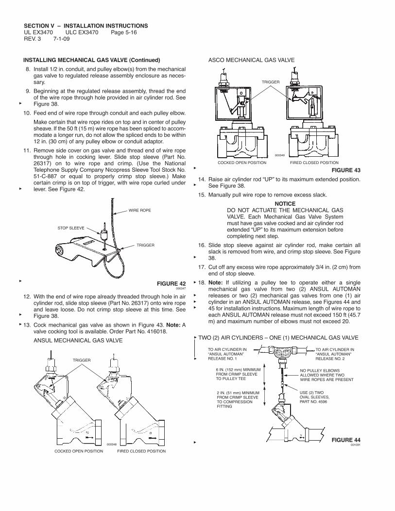
SECTION V – INSTALLATION INSTRUCTIONSUL EX3470 ULC EX3470 Page 5-16REV. 3 7-1-09
INSTALLING MECHANICAL GAS VALVE (Continued)
8. Install 1/2 in. conduit, and pulley elbow(s) from the mechanicalgas valve to regulated release assembly enclosure as neces-sary.
9. Beginning at the regulated release assembly, thread the endof the wire rope through hole provided in air cylinder rod. SeeFigure 38.
10. Feed end of wire rope through conduit and each pulley elbow.
Make certain that wire rope rides on top and in center of pulleysheave. If the 50 ft (15 m) wire rope has been spliced to accom-modate a longer run, do not allow the spliced ends to be within12 in. (30 cm) of any pulley elbow or conduit adaptor.
11. Remove side cover on gas valve and thread end of wire ropethrough hole in cocking lever. Slide stop sleeve (Part No.26317) on to wire rope and crimp. (Use the NationalTelephone Supply Company Nicopress Sleeve Tool Stock No.51-C-887 or equal to properly crimp stop sleeve.) Makecertain crimp is on top of trigger, with wire rope curled underlever. See Figure 42.
FIGURE 42000347
12. With the end of wire rope already threaded through hole in aircylinder rod, slide stop sleeve (Part No. 26317) onto wire ropeand leave loose. Do not crimp stop sleeve at this time. SeeFigure 38.
13. Cock mechanical gas valve as shown in Figure 43. Note: Avalve cocking tool is available. Order Part No. 416018.
ANSUL MECHANICAL GAS VALVE
ASCO MECHANICAL GAS VALVE
FIGURE 43
14. Raise air cylinder rod “UP” to its maximum extended position.See Figure 38.
15. Manually pull wire rope to remove excess slack.
NOTICEDO NOT ACTUATE THE MECHANICAL GASVALVE. Each Mechanical Gas Valve Systemmust have gas valve cocked and air cylinder rodextended “UP” to its maximum extension beforecompleting next step.
16. Slide stop sleeve against air cylinder rod, make certain allslack is removed from wire, and crimp stop sleeve. See Figure38.
17. Cut off any excess wire rope approximately 3/4 in. (2 cm) fromend of stop sleeve.
18. Note: If utilizing a pulley tee to operate either a singlemechanical gas valve from two (2) ANSUL AUTOMANreleases or two (2) mechanical gas valves from one (1) aircylinder in an ANSUL AUTOMAN release, see Figures 44 and45 for installation instructions. Maximum length of wire rope toeach ANSUL AUTOMAN release must not exceed 150 ft (45.7m) and maximum number of elbows must not exceed 20.
FIGURE 44001091
STOP SLEEVE
WIRE ROPE
TRIGGER
TRIGGER
COCKED OPEN POSITION FIRED CLOSED POSITION
000349
TRIGGER
COCKED OPEN POSITION FIRED CLOSED POSITION
000348
TO AIR CYLINDER IN“ANSUL AUTOMAN”RELEASE NO. 1
TO AIR CYLINDER IN“ANSUL AUTOMAN”RELEASE NO. 2
2 IN. (51 mm) MINIMUMFROM CRIMP SLEEVETO COMPRESSIONFITTING
6 IN. (152 mm) MINIMUMFROM CRIMP SLEEVETO PULLEY TEE
USE (2) TWOOVAL SLEEVES,PART NO. 4596
NO PULLEY ELBOWSALLOWED WHERE TWOWIRE ROPES ARE PRESENT
TWO (2) AIR CYLINDERS – ONE (1) MECHANICAL GAS VALVE
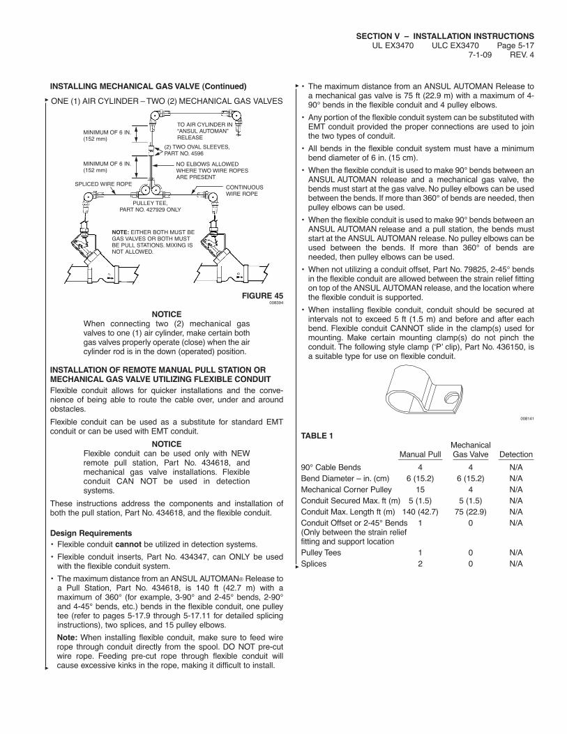
SECTION V – INSTALLATION INSTRUCTIONSUL EX3470 ULC EX3470 Page 5-17
7-1-09 REV. 4
INSTALLING MECHANICAL GAS VALVE (Continued)
FIGURE 45008394
NOTICEWhen connecting two (2) mechanical gasvalves to one (1) air cylinder, make certain bothgas valves properly operate (close) when the aircylinder rod is in the down (operated) position.
INSTALLATION OF REMOTE MANUAL PULL STATION ORMECHANICAL GAS VALVE UTILIZING FLEXIBLE CONDUITFlexible conduit allows for quicker installations and the conve-nience of being able to route the cable over, under and aroundobstacles.
Flexible conduit can be used as a substitute for standard EMTconduit or can be used with EMT conduit.
NOTICEFlexible conduit can be used only with NEWremote pull station, Part No. 434618, andmechanical gas valve installations. Flexibleconduit CAN NOT be used in detectionsystems.
These instructions address the components and installation ofboth the pull station, Part No. 434618, and the flexible conduit.
Design Requirements• Flexible conduit cannot be utilized in detection systems.
• Flexible conduit inserts, Part No. 434347, can ONLY be usedwith the flexible conduit system.
• The maximum distance from an ANSUL AUTOMAN® Release toa Pull Station, Part No. 434618, is 140 ft (42.7 m) with amaximum of 360° (for example, 3-90° and 2-45° bends, 2-90°and 4-45° bends, etc.) bends in the flexible conduit, one pulleytee (refer to pages 5-17.9 through 5-17.11 for detailed splicinginstructions), two splices, and 15 pulley elbows.
Note: When installing flexible conduit, make sure to feed wirerope through conduit directly from the spool. DO NOT pre-cutwire rope. Feeding pre-cut rope through flexible conduit willcause excessive kinks in the rope, making it difficult to install.
• The maximum distance from an ANSUL AUTOMAN Release toa mechanical gas valve is 75 ft (22.9 m) with a maximum of 4-90° bends in the flexible conduit and 4 pulley elbows.
• Any portion of the flexible conduit system can be substituted withEMT conduit provided the proper connections are used to jointhe two types of conduit.
• All bends in the flexible conduit system must have a minimumbend diameter of 6 in. (15 cm).
• When the flexible conduit is used to make 90° bends between anANSUL AUTOMAN release and a mechanical gas valve, thebends must start at the gas valve. No pulley elbows can be usedbetween the bends. If more than 360° of bends are needed, thenpulley elbows can be used.
• When the flexible conduit is used to make 90° bends between anANSUL AUTOMAN release and a pull station, the bends muststart at the ANSUL AUTOMAN release. No pulley elbows can beused between the bends. If more than 360° of bends areneeded, then pulley elbows can be used.
• When not utilizing a conduit offset, Part No. 79825, 2-45° bendsin the flexible conduit are allowed between the strain relief fittingon top of the ANSUL AUTOMAN release, and the location wherethe flexible conduit is supported.
• When installing flexible conduit, conduit should be secured atintervals not to exceed 5 ft (1.5 m) and before and after eachbend. Flexible conduit CANNOT slide in the clamp(s) used formounting. Make certain mounting clamp(s) do not pinch theconduit. The following style clamp (‘P’ clip), Part No. 436150, isa suitable type for use on flexible conduit.
008141
TABLE 1Mechanical
Manual Pull Gas Valve Detection__________ ________ ________90° Cable Bends 4 4 N/ABend Diameter – in. (cm) 6 (15.2) 6 (15.2) N/AMechanical Corner Pulley 15 4 N/AConduit Secured Max. ft (m) 5 (1.5) 5 (1.5) N/AConduit Max. Length ft (m) 140 (42.7) 75 (22.9) N/AConduit Offset or 2-45° Bends 1 0 N/A(Only between the strain relieffitting and support locationPulley Tees 1 0 N/ASplices 2 0 N/A
MINIMUM OF 6 IN.(152 mm)
MINIMUM OF 6 IN.(152 mm)
SPLICED WIRE ROPECONTINUOUSWIRE ROPE
PULLEY TEE,PART NO. 427929 ONLY
(2) TWO OVAL SLEEVES,PART NO. 4596
NOTE: EITHER BOTH MUST BEGAS VALVES OR BOTH MUSTBE PULL STATIONS. MIXING ISNOT ALLOWED.
NO ELBOWS ALLOWEDWHERE TWO WIRE ROPESARE PRESENT
ONE (1) AIR CYLINDER – TWO (2) MECHANICAL GAS VALVES
TO AIR CYLINDER IN“ANSUL AUTOMAN”RELEASE
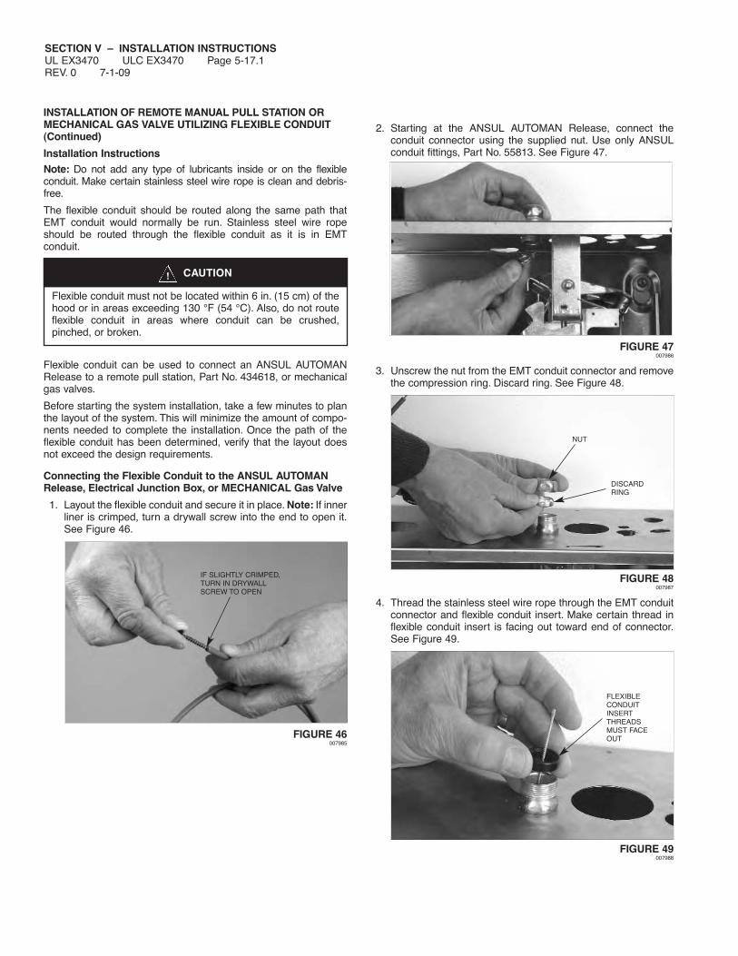
SECTION V – INSTALLATION INSTRUCTIONSUL EX3470 ULC EX3470 Page 5-17.1REV. 0 7-1-09
INSTALLATION OF REMOTE MANUAL PULL STATION ORMECHANICAL GAS VALVE UTILIZING FLEXIBLE CONDUIT(Continued)
Installation InstructionsNote: Do not add any type of lubricants inside or on the flexibleconduit. Make certain stainless steel wire rope is clean and debris-free.
The flexible conduit should be routed along the same path thatEMT conduit would normally be run. Stainless steel wire ropeshould be routed through the flexible conduit as it is in EMTconduit.
Flexible conduit can be used to connect an ANSUL AUTOMANRelease to a remote pull station, Part No. 434618, or mechanicalgas valves.
Before starting the system installation, take a few minutes to planthe layout of the system. This will minimize the amount of compo-nents needed to complete the installation. Once the path of theflexible conduit has been determined, verify that the layout doesnot exceed the design requirements.
Connecting the Flexible Conduit to the ANSUL AUTOMANRelease, Electrical Junction Box, or MECHANICAL Gas Valve
1. Layout the flexible conduit and secure it in place. Note: If innerliner is crimped, turn a drywall screw into the end to open it.See Figure 46.
FIGURE 46007985
2. Starting at the ANSUL AUTOMAN Release, connect theconduit connector using the supplied nut. Use only ANSULconduit fittings, Part No. 55813. See Figure 47.
FIGURE 47 007986
3. Unscrew the nut from the EMT conduit connector and removethe compression ring. Discard ring. See Figure 48.
FIGURE 48 007987
4. Thread the stainless steel wire rope through the EMT conduitconnector and flexible conduit insert. Make certain thread inflexible conduit insert is facing out toward end of connector.See Figure 49.
FIGURE 49007988
IF SLIGHTLY CRIMPED,TURN IN DRYWALLSCREW TO OPEN
CAUTION!
Flexible conduit must not be located within 6 in. (15 cm) of thehood or in areas exceeding 130 °F (54 °C). Also, do not routeflexible conduit in areas where conduit can be crushed,pinched, or broken.
FLEXIBLECONDUITINSERTTHREADSMUST FACEOUT
NUT
DISCARDRING

SECTION V – INSTALLATION INSTRUCTIONSUL EX3470 ULC EX3470 Page 5-17.2
7-1-09 REV. 0
INSTALLATION OF REMOTE MANUAL PULL STATION ORMECHANICAL GAS VALVE UTILIZING FLEXIBLE CONDUIT(Continued)Connecting the Flexible Conduit to the ANSUL AUTOMANRelease, Electrical Junction Box, or Mechanical Gas Valve(Continued)
5. Tighten the nut to the connector body, locking the flexibleconduit insert in place. See Figure 50.
FIGURE 50007989
6. Loosen the nut on the strain relief and thread the wire ropethrough a strain relief. See Figure 51.
FIGURE 51007990
7. Tighten the body of the strain relief to the conduit connector.See Figure 52.
FIGURE 52007991
8. Thread the wire rope through the flexible conduit. See Figure53. (If a splice is required in the flexible conduit, proceed to“Splicing Installation Instructions.”
FIGURE 53007992
9. Slide the flexible conduit into the strain relief until it is approx-imately 1/16 in. (2 mm) from the bottom of the flexible conduitinsert. See Figure 54.
FIGURE 54007993
10. Tighten the strain relief nut onto the strain relief. See Figure55.
FIGURE 55007994
TIGHTENSTRAIN RELIEFINTO CONDUITCONNECTOR
TIGHTENCONNECTORNUT TO LOCKIN FLEXIBLECONDUITINSERT
LOOSENNUT
TIGHTEN NUTON STRAINRELIEF
STOP FLEXIBLECONDUITAPPROXIMATELY1/16 IN. (2 mm)FROM THE BOTTOMOF INTERNALFLEXIBLE CONDUITINSERT
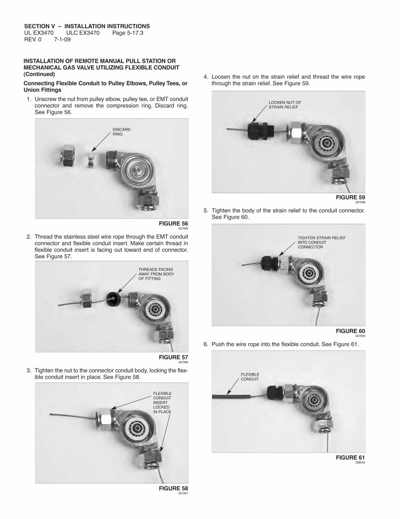
SECTION V – INSTALLATION INSTRUCTIONSUL EX3470 ULC EX3470 Page 5-17.3REV. 0 7-1-09
INSTALLATION OF REMOTE MANUAL PULL STATION ORMECHANICAL GAS VALVE UTILIZING FLEXIBLE CONDUIT(Continued)
Connecting Flexible Conduit to Pulley Elbows, Pulley Tees, orUnion Fittings
1. Unscrew the nut from pulley elbow, pulley tee, or EMT conduitconnector and remove the compression ring. Discard ring.See Figure 56.
FIGURE 56007995
2. Thread the stainless steel wire rope through the EMT conduitconnector and flexible conduit insert. Make certain thread inflexible conduit insert is facing out toward end of connector.See Figure 57.
FIGURE 57007996
3. Tighten the nut to the connector conduit body, locking the flex-ible conduit insert in place. See Figure 58.
FIGURE 58007997
4. Loosen the nut on the strain relief and thread the wire ropethrough the strain relief. See Figure 59.
FIGURE 59007998
5. Tighten the body of the strain relief to the conduit connector.See Figure 60.
FIGURE 60007999
6. Push the wire rope into the flexible conduit. See Figure 61.
FIGURE 61008000
FLEXIBLECONDUITINSERTLOCKEDIN PLACE
DISCARDRING
THREADS FACINGAWAY FROM BODYOF FITTING
FLEXIBLECONDUIT
LOOSEN NUT OFSTRAIN RELIEF
TIGHTEN STRAIN RELIEFINTO CONDUITCONNECTOR

SECTION V – INSTALLATION INSTRUCTIONSUL EX3470 ULC EX3470 Page 5-17.4
7-1-09 REV. 0
INSTALLATION OF REMOTE MANUAL PULL STATION ORMECHANICAL GAS VALVE UTILIZING FLEXIBLE CONDUIT(Continued)
Connecting Flexible Conduit to Pulley Elbows, Pulley Tees, orUnion Fittings (Continued)
7. Slide the flexible conduit into the strain relief until it is approx-imately 1/16 in. (2 mm) from the bottom of the flexible conduitinsert. See Figure 62.
FIGURE 62008001
8. Tighten the strain relief nut onto the strain relief. See Figure63.
FIGURE 63 008002
9. Complete the same procedures on the other end of theconduit fitting as described in Steps 1 through Step 8 above.
Assembling the Block
Note: For installations that do not require the tee block, referto page 5-17.12 for instructions.
1. The flexible conduit and wire rope should be connected to theelectrical box as described in “Connecting the FlexibleConduit to the ANSUL AUTOMAN Release, Electrical Box, orMechanical Gas Valve.” See Figure 64.
Note: For 1 1/2 in. (3.8 cm) deep electrical box, the bearingshould be installed in the block’s shallow box location.
For 2 1/8 in. (5.4 cm) deep electrical box, the bearing shouldbe installed in the block’s deep box location.
FIGURE 64008003
2. Thread the wire rope through the small end of the block intothe bearing area to be used. See Figure 65.
FIGURE 65008004
3. Pull slack, make a loop and insert the rope through the largeropening in the bearing area. See Figure 66.
FIGURE 66008005
SLIDE FLEXIBLE CONDUITAPPROXIMATELY 1/16 IN.(2 mm) FROM BOTTOM OFFLEXIBLE CONDUIT INSERT
TIGHTEN STRAINRELIEF NUT SMALL END
OF BLOCK
PUSH WIRE ROPETHROUGHLARGEROPENING

SECTION V – INSTALLATION INSTRUCTIONSUL EX3470 ULC EX3470 Page 5-17.5REV. 0 7-1-09
INSTALLATION OF REMOTE MANUAL PULL STATION ORMECHANICAL GAS VALVE UTILIZING FLEXIBLE CONDUIT(Continued)
Assembling the Block (Continued)
4. Pull wire rope out of the large end of the block. See Figure 67.
FIGURE 67008006
5. Place the bearing against the wire rope. Make certain wirerope is in the bearing groove. See Figure 68.
FIGURE 68008007
6. Align the bearing against the wire rope so that the bearingcenter and the hole in the block line up. See Figure 69.
FIGURE 69008008
7. Insert the supplied bolt into the bearing and tighten securely.Take care not to strip the thread. See Figure 70.
FIGURE 70008009
Connecting the Block and the Faceplate
1. The block can be inserted into the faceplate at 90° intervals.See Figure 71.
FIGURE 71008010
2. Thread the wire rope through the faceplate. Insert the block bydepressing the tabs and pushing the block into the faceplateuntil it snaps in place. See Figure 72.
FIGURE 72008011
BEARINGGROOVE
CAN BE INSERTEDAT 90° INTERVALS
PUSH BLOCKINTOFACEPLATE

SECTION V – INSTALLATION INSTRUCTIONSUL EX3470 ULC EX3470 Page 5-17.6
7-1-09 REV. 0
INSTALLATION OF REMOTE MANUAL PULL STATION ORMECHANICAL GAS VALVE UTILIZING FLEXIBLE CONDUIT(Continued)
Connecting the Block and the Faceplate (Continued)
3. Place the faceplate over the top of the electrical box and insertthe two screws to secure the faceplate. See Figure 73.
FIGURE 73008012
4. Thread the wire rope through the pull knob. See Figure 74.
FIGURE 74008013
5. Thread the wire rope through stop sleeve and leave approxi-mately 1/4-3/8 in. extended past sleeve. Crimp the stop sleevetwice using Crimping tool, National Telephone Supply Co.Nicopress Sleeve Tool (Stock No. 51-C-887). Verify the stopsleeve is secure on the wire rope. See Figure 75.
FIGURE 75008014
6. Insert the break rod into the two holes toward the top of thepull knob. See Figure 76.
FIGURE 76008015
7. Pull the excess slack back to the ANSUL AUTOMAN Release.This will pull the pull knob assembly in place. See Figure 77.
FIGURE 77008016
8. Hold the pull knob assembly against the faceplate. Rotate thepull knob assembly counterclockwise until the break rod andpull knob snap in place. See Figure 78.
Note: Take care in snapping in the ends of the break rod intothe pull station side shields while rotating the entire assembly.
FIGURE 78008017
LEAVE 1/4-3/8 IN.(6-9 mm)
ROTATECOUNTER-CLOCKWISE
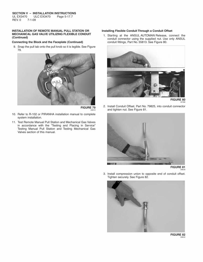
SECTION V – INSTALLATION INSTRUCTIONSUL EX3470 ULC EX3470 Page 5-17.7REV. 0 7-1-09
INSTALLATION OF REMOTE MANUAL PULL STATION ORMECHANICAL GAS VALVE UTILIZING FLEXIBLE CONDUIT(Continued)
Connecting the Block and the Faceplate (Continued)
9. Snap the pull tab onto the pull knob so it is legible. See Figure79.
FIGURE 79008018
10. Refer to R-102 or PIRANHA installation manual to completesystem installation.
11. Test Remote Manual Pull Station and Mechanical Gas Valvesin accordance with the “Testing and Placing in Service”Testing Manual Pull Station and Testing Mechanical GasValves section of this manual.
Installing Flexible Conduit Through a Conduit Offset
1. Starting at the ANSUL AUTOMAN Release, connect theconduit connector using the supplied nut. Use only ANSULconduit fittings, Part No. 55813. See Figure 80.
FIGURE 80 007986
2. Install Conduit Offset, Part No. 79825, into conduit connectorand tighten nut. See Figure 81.
FIGURE 81 008039
3. Install compression union to opposite end of conduit offset.Tighten securely. See Figure 82.
FIGURE 82 008040

SECTION V – INSTALLATION INSTRUCTIONSUL EX3470 ULC EX3470 Page 5-17.8
7-1-09 REV. 0
INSTALLATION OF REMOTE MANUAL PULL STATION ORMECHANICAL GAS VALVE UTILIZING FLEXIBLE CONDUIT(Continued)
Installing Flexible Conduit Through a Conduit Offset(Continued)
4. Install the conduit required to get above the ceiling. SeeFigure 83.
FIGURE 83 008041
5. Install compression union to top of conduit riser. See Figure84.
FIGURE 84 008042
6. Remove union nut and ring. Discard ring. Do not reinstall nutat this time. See Figure 85.
FIGURE 85 008043
7. Remove strain relief nut and install strain relief body intocompression union. See Figure 86.
FIGURE 86 008044
8. Install union nut over strain relief body and tighten nut. SeeFigure 87.
FIGURE 87 008045
9. Install strain relief nut onto strain relief body. Do not tighten nutat this time. See Figure 88.
FIGURE 88 008046
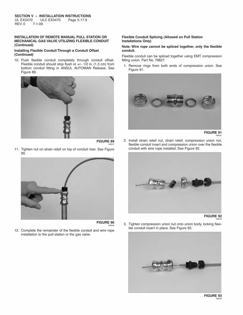
SECTION V – INSTALLATION INSTRUCTIONSUL EX3470 ULC EX3470 Page 5-17.9REV. 0 7-1-09
INSTALLATION OF REMOTE MANUAL PULL STATION ORMECHANICAL GAS VALVE UTILIZING FLEXIBLE CONDUIT(Continued)
Installing Flexible Conduit Through a Conduit Offset(Continued)
10. Push flexible conduit completely through conduit offset.Flexible conduit should stop flush or +/– 1/2 in. (1.3 cm) frombottom conduit fitting in ANSUL AUTOMAN Release. SeeFigure 89.
FIGURE 89 008047
11. Tighten nut on strain relief on top of conduit riser. See Figure90.
FIGURE 90 008048
12. Complete the remainder of the flexible conduit and wire ropeinstallation to the pull station or the gas valve.
Flexible Conduit Splicing (Allowed on Pull StationInstallations Only)
Note: Wire rope cannot be spliced together, only the flexibleconduit.
Flexible conduit can be spliced together using EMT compressionfitting union, Part No. 79827.
1. Remove rings from both ends of compression union. SeeFigure 91.
FIGURE 91 008061
2. Install strain relief nut, strain relief, compression union nut,flexible conduit insert and compression union over the flexibleconduit with wire rope installed. See Figure 92.
FIGURE 92 008049
3. Tighten compression union nut onto union body, locking flexi-ble conduit insert in place. See Figure 93.
FIGURE 93 008050

SECTION V – INSTALLATION INSTRUCTIONSUL EX3470 ULC EX3470 Page 5-17.10
7-1-09 REV. 0
INSTALLATION OF REMOTE MANUAL PULL STATION ORMECHANICAL GAS VALVE UTILIZING FLEXIBLE CONDUIT(Continued)
Flexible Conduit Splicing (Allowed on Pull StationInstallations Only) (Continued)
4. Install strain relief body into compression union and tighten.See Figure 94.
FIGURE 94 008051
5. Push flexible conduit into strain relief until it is approximately1/16 in. (2 mm) from the bottom of the flexible conduit insert,then tighten strain relief nut onto strain relief body. See Figure95.
FIGURE 95 008052
6. Starting on the opposite end of the compression union,remove the nut. See Figure 96.
FIGURE 96 008053
7. Install strain relief nut, strain relief, and compression union nuton remaining section of flexible conduit and install flexibleconduit insert on wire rope. See Figure 97.
FIGURE 97 008054
8. Push wire rope completely through remaining section of flexi-ble conduit. See Figure 98.
FIGURE 98 008055
9. Tighten compression union nut onto union body, securing flex-ible conduit insert in place. See Figure 99.
FIGURE 99 008056

SECTION V – INSTALLATION INSTRUCTIONSUL EX3470 ULC EX3470 Page 5-17.11REV. 0 7-1-09
INSTALLATION OF REMOTE MANUAL PULL STATION ORMECHANICAL GAS VALVE UTILIZING FLEXIBLE CONDUIT(Continued)
Flexible Conduit Splicing (Allowed on Pull StationInstallations Only) (Continued)
10. Tighten strain relief into compression union. See Figure 100.
FIGURE 100 008057
11. Push flexible conduit into strain relief until it is approximately1/16 in. (2 mm) from the bottom of the flexible conduit insert,then tighten strain relief nut onto strain relief body. See Figure101.
FIGURE 101 008058
12. Complete the remainder of the flexible conduit and wire ropeinstallation to the pull station or the gas valve.
Component Removal Instructions
Removal of Block
Using thumbs on the clips on each side of the block, press firmlyin the direction of the center of the block, at the same time press-ing in a slightly downward direction. As the clips on the side of theblock release from the pull station cover, the block will release andbe free to be removed from the backside of the cover. See Figure102.
FIGURE 102 007884
Removal of Pull Knob
Insert a small screwdriver into slot at bottom of pull knob. Pushslightly on the screwdriver and turn pull knob clockwise, then pullknob can be removed without breaking the glass rod. See Figure103.
FIGURE 103 008059
Removal of Pull Cap
Using a small screwdriver or other blunt object, push on the back-side of the pull cap. This will free the cap from the pull knob. SeeFigure 104.
FIGURE 104008060

SECTION V – INSTALLATION INSTRUCTIONSUL EX3470 ULC EX3470 Page 5-17.12
7-1-09 REV. 0
INSTALLATION OF REMOTE MANUAL PULL STATION ORMECHANICAL GAS VALVE UTILIZING FLEXIBLE CONDUIT(Continued)
Pull Station Installation without Pulley Block Assembly
Note 1: When using this installation option, the distance fromthe back of the faceplate and the connection to the 1/2 in. EMTconduit compression fitting must not exceed 6 in. (15.2 cm).
Note 2: To provide for a straight run of wire rope from the pullstation, an octagonal junction box with a center knockout in theback of the junction box will be needed. See Figure 104a. If a pre-fabricated box or enclosure is to be used, it must allow the pullstation face plate to be firmly attached to the box or enclosure, witha hole or knockout suitable for a 1/2 in. EMT threaded conduitcompression connector to be installed directly in line with thecenter of the pull station pull knob.
FIGURE 104a008415
1. Attach a 1/2 in. EMT conduit compression fitting (Part No.55813) to the back center knock out of the junction box. Ifsomething other than a junction box is to be utilized, a methodof securing the flexible conduit or EMT conduit directly in linewith the center of the pull station pull knob must be used. Thiswill ensure that in the event of manual operation the wire rope,exiting the back of the pull station faceplate, will be pulledstraight out without binding or resulting in undue additional pullforce due to friction loss.
2. Remove the block assembly from the pull station face plate.Thread the wire rope from either flexible conduit or 1/2 in. EMTconduit attached to the back of the junction box or fabricatedenclosure through the back side of the pull station faceplateand through the pull knob.
3. Thread the wire rope through the stop sleeve (Part No. 26317)and leave approximately 1/4 in. to 3/8 in. (6 mm to 10 mm)extending past the sleeve.
4. Crimp the stop sleeve twice using the crimping tool NationalTelephone Supply Co. Nicopress Sleeve Toll (Stock No, 51-C-887). Verify the sleeve is secure on the wire rope.

SECTION V – INSTALLATION INSTRUCTIONSUL EX3470 ULC EX3470 Page 5-18REV. 6 7-1-09
INSTALLING ELECTRICAL GAS VALVES
NOTICEElectric gas valves are designed for indoorinstallation only.
The following instructions and schematics illustrate methods ofprocedures for installing 110 VAC Electric Gas Shut-off Valves.
1. Make certain that regulated release assembly enclosure coveris detached and lock bar is properly inserted within the regu-lated release mechanism.
NOTICEFailure to follow these instructions may lead tosystem actuation.
2. Verify that cartridge has been removed from regulated releaseassembly and that the regulated release mechanism is in thecocked position.
If regulated release mechanism does not have lock barinserted or cartridge removed, refer to the “Semi-AnnualMaintenance,” Page 8-1, in “Maintenance Examination”section, and complete Steps 2 and 3 before completing thefollowing installation steps.
3.
Install each electric gas valve to its selected location in gasline so that it ensures safe shut-off to all predetermined appli-ances being protected upon actuation of the system. Refer tomanufacturer’s instructions (if provided). See Figure 105.
a. Use new pipe properly reamed and clean of metal chips.
b. Install valve so that the actuator is above the horizontal pipeline with no more than a five degree (5°) lean either way.
c. Make certain gas flow is in the same direction as arrowshown on gas valve.
d. If strainer is utilized, attach strainer ahead of gas valve.
e. If necessary, install drip leg in gas line in accordance withauthority having jurisdiction.
FIGURE 1054. Install and secure 1/2 in. conduit from each electric gas valve
to manual reset relay enclosure.
5. Tag and connect electrical wiring to each electric gas valve.Then, feed wire through conduit to manual reset relay. Tape orplace a wire nut on any unused wire leads in accordance withauthority having jurisdiction. Refer to Figures at the end of thissection for typical wiring diagrams.
6.
Connect electrical wiring to manual reset relay along with anycontactor, or contractor supplied devices needed. Refer tomanufacturer’s instructions and proper figure listed for assis-tance.
7. Tape or place a wire nut on any unused wire leads in accor-dance with authority having jurisdiction.
8. Install and secure 1/2 in. conduit from the regulated releaseassembly enclosure to manual reset relay enclosure.
If snap-action switches have not been attached, go to “ElectricSwitch” section and install them at this time by completingSteps 3 through 8.
9. Tag and connect electrical wiring to each electric (snap-action)switch. Then, feed wire through conduit to manual reset relay.
10. Connect wiring from each electric (snap-action) switch tomanual reset relay terminals. Refer to manufacturer’s instruc-tions (if provided) and proper figure for assistance.
11. Tape or place a wire nut on any unused wire leads in accor-dance with authority having jurisdiction.
12. Properly return electrical power to the system.
CAUTION!
To reduce the risk of explosion due to leaking gas, makecertain that the gas line is turned off before connecting thegas valve. Gas valve installation shall be performed byqualified individuals in accordance with local jurisdictionrequirements.
001092
001093
CORRECT WAY:
VISE GRIP ENDS NEXT TO PIPEBEING INSERTED. PREVENTSEXCESS STRAIN ON VALVE BODY.
CORRECT WAY:
WRENCH APPLIED NEXT TO PIPEBEING INSERTED PREVENTSEXCESS STRAIN ON VALVE BODY.
WRONG WAY:
WRENCH APPLIED ATTHIS POINT STRAINSVALVE BODY.
CAUTION!
Before working on any electrical wiring, make certain mainpower has been disconnected. Failure to disconnect mainpower could cause personal injury or death if contact ismade with energized wires.
CAUTION!
All electrical wiring/connections shall be performed byqualified individuals in accordance with local jurisdictionrequirements.

SECTION V – INSTALLATION INSTRUCTIONSUL EX3470 ULC EX3470 Page 5-19
7-1-09 REV. 5
INSTALLING ELECTRICAL SWITCHES
The procedure for field installing an electric (snap-action) switch isas follows:
NOTICEExcept for the Alarm Initiating Switch, all electri-cal wiring connections are to be made outsidethe ANSUL AUTOMAN Release enclosure insuitable enclosures in accordance with localjurisdiction requirements.
1. Make certain that regulated release assembly enclosure coveris detached with lock bar properly inserted within the regu-lated release mechanism.
NOTICEFailure to follow these instructions may lead tosystem actuation.
2. Verify that cartridge has been removed from regulated releaseassembly and that the regulated release mechanism is in thecocked position. If regulated release mechanism does nothave lock bar inserted or cartridge removed, refer to the“Semi-Annual Maintenance,” Page 8-1, in “MaintenanceExamination” section, and complete Steps 2 and 3 beforecompleting the following installation steps.
If regulated release mechanism has a factory installed sole-noid, it will also have a factory installed switch.
3. Press each wire assembly onto the 3-terminals located on theswitch(s). Be sure that the connector is pressed tight againstthe switch. See Figure 106.
FIGURE 106001621
4. Install switch(es) to the mounting bracket using providedfasteners and tighten securely.
5. If more than one switch is being installed, it is necessary toattach the trip lever extension stud to the trip lever. See Figure107. Using the provided fasteners, securely install the exten-sion stud.
6. Raise switch actuating arm squarely over the cam surface ofthe trip lever. This will allow the trip lever, when actuated, toforce the actuating arm “UP,” thus reversing the normal condi-tion of the switch. See Figure 107.
For multiple switch installations, make certain switch actuatingarms are positioned on trip lever extension stud.
Before proceeding with Step 7, test electric (snap-action)switches:
a. Remove lock bar. With the ANSUL AUTOMAN in thecocked or ready position, press the lever of each switch up.If the switch is working properly there should be an audibleclick.
b. With the ANSUL AUTOMAN in the fired position, press thelever of each switch up, there should be no audible click.
When installing multiple switches, make certain all switchestransfer when the release operates. If they do not, readjusttheir position.
c. If an audible click is heard in the fired position severaladjustments can be made. The trip lever extension pin canbe rotated so the peak of one of the hex points is pointedup against the switch levers.Tighten it in that position. If thisdoesn’t resolve the problem, loosen the screws holding theswitches, apply a small counterclockwise torque on theswitches and retighten the screws. If necessary, a finaladjustment can be made by removing the snap actionswitch and bending the lever slightly.
d. After adjustments repeat steps a and b. Then, recockANSUL AUTOMAN and install lock bar.
FIGURE 107
7. The switch may now be connected to compatible componentsthat are predetermined to shut off or turn on. Refer to compo-nent manufacturer’s instructions for proper wiring connectionsto compatible components.
CAUTION!
Unused wire leads will become “hot” when the system is oper-ated. Failure to adequately cover exposed wire end(s) willcause electric shock if touched.
CAUTION!
Before working on any electrical wiring, make certain mainpower has been disconnected. Failure to disconnect mainpower could cause personal injury or death if contact is madewith energized wires.
CAUTION!
All electrical wiring/connections shall be performed by qualifiedindividuals in accordance with local jurisdiction requirements.
SNAP-ACTIONSWITCH
ACTUATINGARM
COMMON
BLACK
RED
BROWNN.C.
N.O.
PRESS CONNECTORTIGHTLY AGAINST SWITCH
NOTE: SWITCH SHOWN IN NORMAL POSITION
RED
BLACK
BROWN
ACTUATING ARM
MOUNTING HOLE FOR TRIPLEVER EXTENSION
TRIP LEVEREXTENSION STUD
001624
002298

SECTION V – INSTALLATION INSTRUCTIONSUL EX3470 ULC EX3470 Page 5-20REV. 3 7-1-09
INSTALLING ELECTRICAL SWITCHES (Continued)
NOTICEExcept for the Alarm Initiating Switch, all electri-cal wiring connections are to be made outsidethe ANSUL AUTOMAN Release enclosure insuitable enclosures in accordance with localjurisdiction requirements.
8. Tape or place a wire nut on any unused wire leads in accor-dance with authority having jurisdiction.
NOTICEDo not connect power source to any relay,contactor, or contractor supplied devices until allother electrical connections are made. Refer toproper section or manufacturer supplied instruc-tions for recommended installation proceduresfor these devices.
9. Turn off power source and connect power line to any relay,contactor, or contractor supplied devices where used.
INSTALLING ALARM INITIATING SWITCH
The Alarm Initiating Switch Kit, Part No. 428311, consists of:
• Alarm Initiating Switch Assembly – Rated 50 mA 28VDC
• Spacer
• Mounting Screw with Nut (2)
• Extension Pin
• Extension Pin Nut
• Instruction Sheet
The Alarm Initiating Switch is mounted in the ANSUL AUTOMANRelease on the same mounting plate where the current snap-action switches are mounted. If the alarm initiating switch is usedalone, the enclosed extension pin and pin nut are not needed.
When mounting the switch, the spacer must be installed first,between the ANSUL AUTOMAN mounting plate (or existingswitches) and the alarm initiating switch.
See NFPA 72, “National Fire Alarm Code,” Initiating Devicessection, for the correct method of wiring connection to the firealarm panel.
After the switch is properly mounted, follow the steps listed in theinstallation section of the Design, Installation, Recharge, andMaintenance Manual for correct positioning of the switch lever onthe ANSUL AUTOMAN cam surface.
FIGURE 108004890
FIGURE 109
Note: With the exception of the Alarm Initiating Switch, all electri-cal connections must be made in an approved electrical box whichalso meets NEC article 314.40 (D) Grounding Provisions.
ALARM INITIATINGSWITCH
WHEN SPACER ANDSWITCH ARE PROPERLYMOUNTED, THIS DIVIDERMUST BE BETWEEN THEN.O. AND N.C. TERMINALS
TOWARDAUTOMAN
N.O.
COM
SPACER
N.C.
FIRE ALARMCONTROL PANEL
ALARMCIRCUIT
ALARM INITIATINGSWITCH
END-OF-LINE RESISTOROR NEXT DEVICE
INCORRECT
ININ OUT
CORRECT – SEPARATE INCOMING AND OUTGOING CONDUCTORS
OUT004905
004891
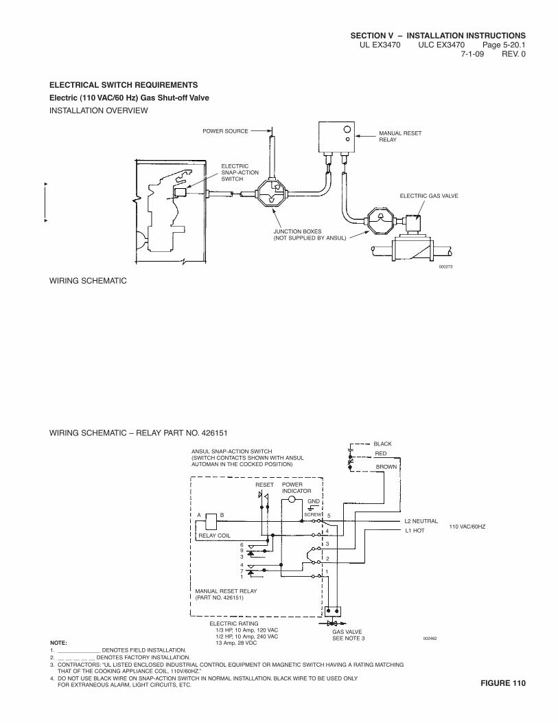
SECTION V – INSTALLATION INSTRUCTIONSUL EX3470 ULC EX3470 Page 5-20.1
7-1-09 REV. 0
ELECTRICAL SWITCH REQUIREMENTS
Electric (110 VAC/60 Hz) Gas Shut-off Valve
INSTALLATION OVERVIEW
WIRING SCHEMATIC
WIRING SCHEMATIC – RELAY PART NO. 426151
FIGURE 110
POWER SOURCE
ELECTRICSNAP-ACTIONSWITCH
MANUAL RESETRELAY
ELECTRIC GAS VALVE
JUNCTION BOXES(NOT SUPPLIED BY ANSUL)
000273
ANSUL SNAP-ACTION SWITCH(SWITCH CONTACTS SHOWN WITH ANSULAUTOMAN IN THE COCKED POSITION)
BLACK
RED
BROWN
RESET POWERINDICATOR
A B
RELAY COIL
SCREW
GND
5
4
3
2
1
693
471
MANUAL RESET RELAY(PART NO. 426151)
ELECTRIC RATING1/3 HP, 10 Amp, 120 VAC1/2 HP, 10 Amp, 240 VAC13 Amp, 28 VDC
GAS VALVESEE NOTE 3
L2 NEUTRAL
L1 HOT110 VAC/60HZ
002462NOTE:1. ______________ DENOTES FIELD INSTALLATION.2. __ __ __ __ __ DENOTES FACTORY INSTALLATION.3. CONTRACTORS: “UL LISTED ENCLOSED INDUSTRIAL CONTROL EQUIPMENT OR MAGNETIC SWITCH HAVING A RATING MATCHING
THAT OF THE COOKING APPLIANCE COIL, 110V/60HZ.”4. DO NOT USE BLACK WIRE ON SNAP-ACTION SWITCH IN NORMAL INSTALLATION. BLACK WIRE TO BE USED ONLY
FOR EXTRANEOUS ALARM, LIGHT CIRCUITS, ETC.
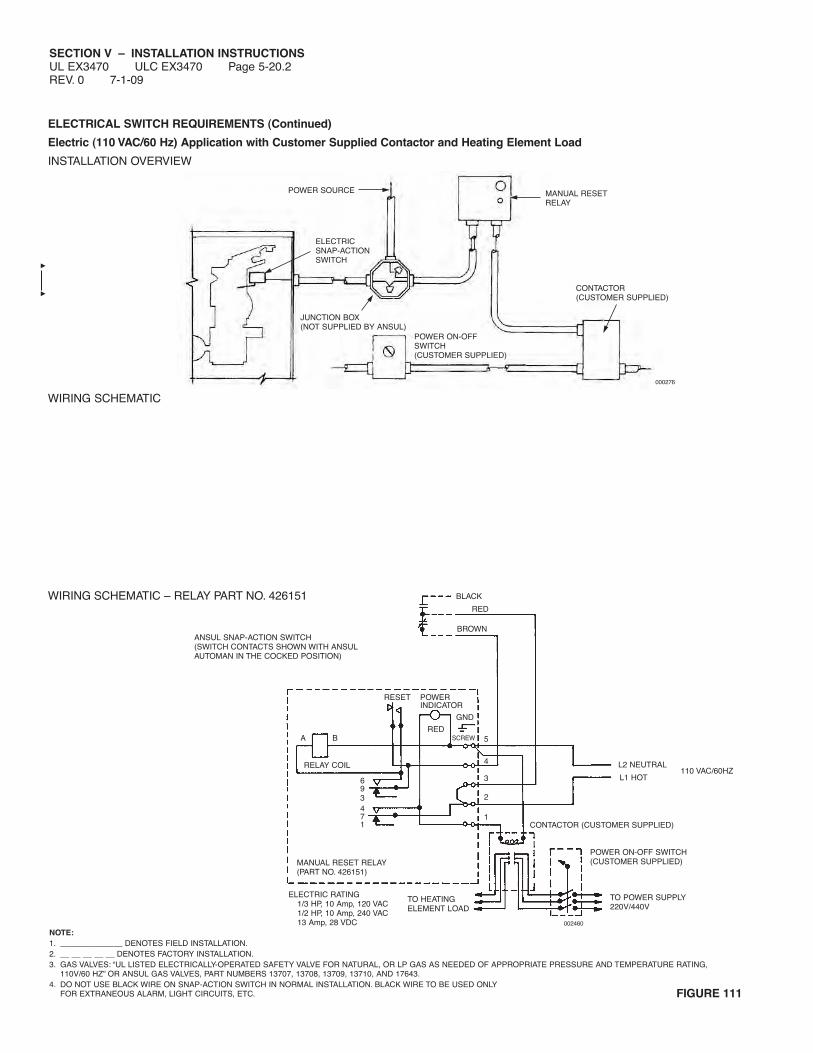
SECTION V – INSTALLATION INSTRUCTIONSUL EX3470 ULC EX3470 Page 5-20.2REV. 0 7-1-09
ELECTRICAL SWITCH REQUIREMENTS (Continued)
Electric (110 VAC/60 Hz) Application with Customer Supplied Contactor and Heating Element Load
INSTALLATION OVERVIEW
WIRING SCHEMATIC
WIRING SCHEMATIC – RELAY PART NO. 426151
FIGURE 111
POWER SOURCE
ELECTRICSNAP-ACTIONSWITCH
MANUAL RESETRELAY
CONTACTOR(CUSTOMER SUPPLIED)
POWER ON-OFFSWITCH(CUSTOMER SUPPLIED)
JUNCTION BOX(NOT SUPPLIED BY ANSUL)
000276
MANUAL RESET RELAY(PART NO. 426151)
BLACK
RED
BROWNANSUL SNAP-ACTION SWITCH(SWITCH CONTACTS SHOWN WITH ANSULAUTOMAN IN THE COCKED POSITION)
RESET POWERINDICATOR
GND
REDSCREWBA
RELAY COIL
693471
5
4
3
2
1
L2 NEUTRAL
L1 HOT110 VAC/60HZ
CONTACTOR (CUSTOMER SUPPLIED)
POWER ON-OFF SWITCH(CUSTOMER SUPPLIED)
TO POWER SUPPLY220V/440V
002460
TO HEATINGELEMENT LOAD
ELECTRIC RATING1/3 HP, 10 Amp, 120 VAC1/2 HP, 10 Amp, 240 VAC13 Amp, 28 VDC
NOTE:1. ______________ DENOTES FIELD INSTALLATION.2. __ __ __ __ __ DENOTES FACTORY INSTALLATION.3. GAS VALVES: “UL LISTED ELECTRICALLY-OPERATED SAFETY VALVE FOR NATURAL, OR LP GAS AS NEEDED OF APPROPRIATE PRESSURE AND TEMPERATURE RATING,
110V/60 HZ” OR ANSUL GAS VALVES, PART NUMBERS 13707, 13708, 13709, 13710, AND 17643.4. DO NOT USE BLACK WIRE ON SNAP-ACTION SWITCH IN NORMAL INSTALLATION. BLACK WIRE TO BE USED ONLY
FOR EXTRANEOUS ALARM, LIGHT CIRCUITS, ETC.

SECTION V – INSTALLATION INSTRUCTIONSUL EX3470 ULC EX3470 Page 5-20.3
7-1-09 REV. 0
ELECTRICAL SWITCH REQUIREMENTS (Continued)
Electric (110 VAC/60 Hz) Application with Customer Supplied Contactor and Heating Element Load, and Power Supply Switch
INSTALLATION OVERVIEW
WIRING SCHEMATIC
WIRING SCHEMATIC – RELAY PART NO. 426151
FIGURE 112
NOTE:1. ______________ DENOTES FIELD INSTALLATION.2. __ __ __ __ __ DENOTES FACTORY INSTALLATION.3. CONTRACTORS: “UL LISTED ENCLOSED INDUSTRIAL CONTROL EQUIPMENT OR MAGNETIC SWITCH HAVING A RATING MATCHING THAT OF THE
COOKING APPLIANCE COIL, 110V/60HZ.”4. DO NOT USE BLACK WIRE ON SNAP-ACTION SWITCH IN NORMAL INSTALLATION. BLACK WIRE TO BE USED ONLY
FOR EXTRANEOUS ALARM, LIGHT CIRCUITS, ETC.
POWER SOURCE
ELECTRICSNAP-ACTIONSWITCH
JUNCTION BOX(NOT SUPPLIED BY ANSUL)
MANUAL RESETRELAY
SWITCH ORTHERMOSTAT(CUSTOMER SUPPLIED)
CONTACTOR(CUSTOMER SUPPLIED)
000279
RELAY COIL
ANSUL SNAP-ACTION SWITCH(SWITCH CONTACTS SHOWN WITH ANSULAUTOMAN IN THE COCKED POSITION)
BLACKRED
BROWN
RESET
BARED
POWERINDICATOR
GND
SCREW 5
4
3
2
1
693471
MANUAL RESET RELAY(PART NO. 426151)
ELECTRIC RATING1/3 HP, 10 Amp, 120 VAC1/2 HP, 10 Amp, 240 VAC13 Amp, 28 VDC
SWITCH OR THERMOSTAT(CUSTOMER SUPPLIED)
TO HEATINGELEMENT LOAD
L2 NEUTRAL
L1 HOT110 VAC/60HZ
CONTACTOR(CUSTOMER SUPPLIED)
TO POWER SUPPLY220V/440V
002461

SECTION V – INSTALLATION INSTRUCTIONSUL EX3470 ULC EX3470 Page 5-20.4REV. 0 7-1-09
NOTES:
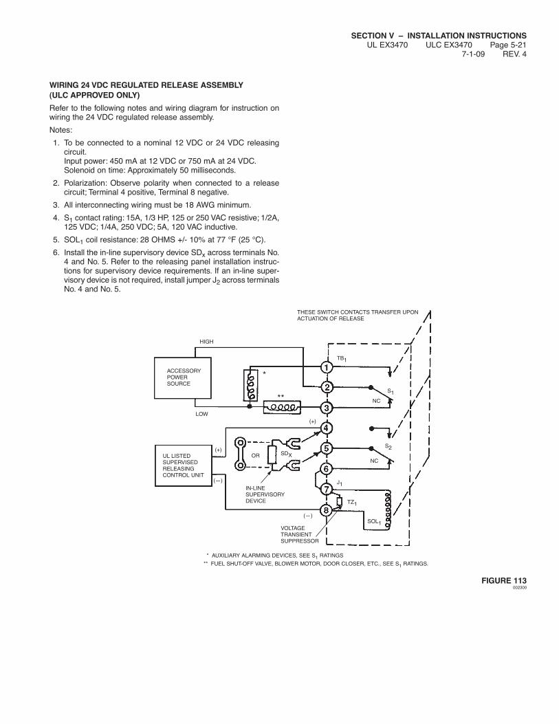
SECTION V – INSTALLATION INSTRUCTIONSUL EX3470 ULC EX3470 Page 5-21
7-1-09 REV. 4
WIRING 24 VDC REGULATED RELEASE ASSEMBLY(ULC APPROVED ONLY)
Refer to the following notes and wiring diagram for instruction onwiring the 24 VDC regulated release assembly.
Notes:
1. To be connected to a nominal 12 VDC or 24 VDC releasingcircuit.Input power: 450 mA at 12 VDC or 750 mA at 24 VDC.Solenoid on time: Approximately 50 milliseconds.
2. Polarization: Observe polarity when connected to a releasecircuit; Terminal 4 positive, Terminal 8 negative.
3. All interconnecting wiring must be 18 AWG minimum.
4. S1 contact rating: 15A, 1/3 HP, 125 or 250 VAC resistive; 1/2A,125 VDC; 1/4A, 250 VDC; 5A, 120 VAC inductive.
5. SOL1 coil resistance: 28 OHMS +/- 10% at 77 °F (25 °C).
6. Install the in-line supervisory device SDx across terminals No.4 and No. 5. Refer to the releasing panel installation instruc-tions for supervisory device requirements. If an in-line super-visory device is not required, install jumper J2 across terminalsNo. 4 and No. 5.
FIGURE 113002300
HIGH
ACCESSORYPOWERSOURCE
LOW
*
THESE SWITCH CONTACTS TRANSFER UPONACTUATION OF RELEASE
TB1
**
(+)UL LISTEDSUPERVISEDRELEASINGCONTROL UNIT
(—)
(+)
S1
NC
SDXOR
IN-LINESUPERVISORYDEVICE
(—)
TZ1
J1
SOL1
NC
S2
VOLTAGETRANSIENTSUPPRESSOR
* AUXILIARY ALARMING DEVICES, SEE S1 RATINGS
** FUEL SHUT-OFF VALVE, BLOWER MOTOR, DOOR CLOSER, ETC., SEE S1 RATINGS.

SECTION V – INSTALLATION INSTRUCTIONSUL EX3470 ULC EX3470 Page 5-22REV. 4 7-1-09
NOTES:

SECTION VI – TESTING AND PLACING IN SERVICEUL EX3470 ULC EX3470 Page 6-1
7-1-09 REV. 3
After the system has been completely installed, and BEFOREINSTALLING THE CARTRIDGE, the system must be tested at theregulated release assembly. The testing information listed in thissection deals with the limitations and parameters of this pre-engi-neered system. Those individuals responsible for the testing of theR-102 system must be trained and hold a current ANSUL certifi-cate in an R-102 training program.
Note: ANSUL AUTOMAN Release must be in the cocked positionbefore testing manual pull station. Make certain to remove lock barbefore performing pull station testing.
TESTING MANUAL PULL STATION
To test each remote manual pull station, complete the followingsteps:
1. With the expellant gas cartridge removed, remove lock barfrom regulated release assembly cable lever.
2. On pull station, remove break rod from the pull station byinserting a small screwdriver into slot at bottom of pull knob tofacilitate turning the pull knob. Push slightly on the screwdriverand turn pull knob clockwise, then the pull knob can beremoved without breaking the glass rod.
NOTICETake care in removing the break rod from thepull station side shields while rotating the breakrod/pull knob assembly.
3. Pull ring handle on pull station. If the regulated releaseassembly is tripped easily, the remote manual pull station isproperly installed. If the regulated release assembly does nottrip, remove pulley tee (if provided) and each pulley elbowcover to make certain wire rope is resting on the pulleysheave. If this does not correct the problem, there is too muchslack in the line and it must be retightened.
4. Recock regulated release assembly using cocking lever (PartNo. 14995 or 435603) and reinstall lock bar (Part No. 14985).
5. On pull station, insert the break rod into the two holes towardthe top of the pull knob. Rotate the pull knob counterclockwise.
NOTICETake care in snapping in the ends of the breakrod into the pull station side shields while rotat-ing the entire assembly.
NOTICEIf no other devices are being attached, proceedto Page 6-3, Step No. 1, and test the detectionsystem.
TESTING MECHANICAL GAS VALVES
To test each mechanical gas shut-off valve complete the followingsteps:
1.
Turn gas line on.
2. Manually push each air cylinder rod to full ‘‘DOWN’’ position.The gas valve should close. If mechanical gas valve does nottrip, remove each pulley elbow cover to make certain wire ropeis resting on each pulley elbow sheave. If this does not correctthe problem there may be too much slack in the line and itshould be retightened.
3. Test for gas leaks by painting connections with a soap solu-tion. Bubbles indicate a gas leak. Tighten connections whereleaks appear and repeat test again to make certain no othergas leaks exist.
4. If no gas leak is found, pull air cylinder rod to full ‘‘UP’’ position.
5. Recock mechanical gas valve.
6. Check burners for gaseous odor. IF GASEOUS ODOREXISTS, MANUALLY PUSH THE AIR CYLINDER ROD TOTHE FULL ‘‘DOWN’’ POSITION IMMEDIATELY. This willcause the mechanical gas valve to shut the gas line off.
Open any doors and/or windows to clear the area of gaseousfumes, then correct the gas leak before proceeding anyfurther.
7. If no gaseous odor exists, pilot light may be ignited at this time.
8. Reinstall side covers to gas valve housing. Make certain rollpin is positioned within both sides of the valve housing slot.Connect visual inspection seals (Part No. 197) on ANSUL typevalves. See Figure 1.
FIGURE 1000359
9. Make certain the regulated release mechanism is cocked withlock bar in place.
NOTICEIf no other devices are being attached, proceedto Page 6-3, Step No. 1, and test the detectionsystem.
CAUTION!
To reduce the risk of explosion due to leaking gas, beforethe gas line is turned on, make certain to extinguish anyopen flames and turn off all burners and any electrical ormechanical devices that are capable of igniting gas.
VISUAL INSPECTIONSEAL (PART NO. 197)
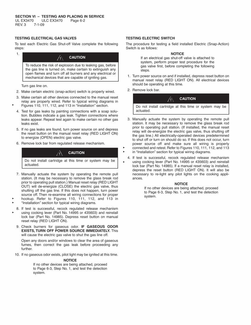
SECTION VI – TESTING AND PLACING IN SERVICEUL EX3470 ULC EX3470 Page 6-2REV. 3 7-1-09
CAUTION!
To reduce the risk of explosion due to leaking gas, beforethe gas line is turned on, make certain to extinguish anyopen flames and turn off all burners and any electrical ormechanical devices that are capable of igniting gas.
CAUTION!
Do not install cartridge at this time or system may beactuated.
TESTING ELECTRICAL GAS VALVES
To test each Electric Gas Shut-off Valve complete the followingsteps:
1.
Turn gas line on.
2. Make certain electric (snap-action) switch is properly wired.
3. Make certain all other devices connected to the manual resetrelay are properly wired. Refer to typical wiring diagrams inFigures 110, 111, 112, and 113 in ‘‘Installation’’ section.
4. Test for gas leaks by painting connections with a soap solu-tion. Bubbles indicate a gas leak. Tighten connections whereleaks appear. Repeat test again to make certain no other gasleaks exist.
5. If no gas leaks are found, turn power source on and depressthe reset button on the manual reset relay (RED LIGHT ON)to energize (OPEN) electric gas valve.
6. Remove lock bar from regulated release mechanism.
7. Manually actuate the system by operating the remote pullstation. (It may be necessary to remove the glass break rodprior to operating pull station.) Manual reset relay (RED LIGHTOUT) will de-energize (CLOSE) the electric gas valve, thusshutting off the gas line. If this does not happen, turn powersource off. Then re-examine all wiring connections for properhookup. Refer to Figures 110, 111, 112, and 113 in‘‘Installation’’ section for typical wiring diagrams.
8. If test is successful, recock regulated release mechanismusing cocking lever (Part No. 14995 or 435603) and reinstalllock bar (Part No. 14985). Depress reset button on manualreset relay (RED LIGHT ON).
9. Check burners for gaseous odor. IF GASEOUS ODOREXISTS, TURN OFF POWER SOURCE IMMEDIATELY. Thiswill cause the electric gas valve to shut the gas line off.
Open any doors and/or windows to clear the area of gaseousfumes, then correct the gas leak before proceeding anyfurther.
10. If no gaseous odor exists, pilot light may be ignited at this time.
NOTICEIf no other devices are being attached, proceedto Page 6-3, Step No. 1, and test the detectionsystem.
TESTING ELECTRIC SWITCH
The procedure for testing a field installed Electric (Snap-Action)Switch is as follows:
NOTICEIf an electrical gas shut-off valve is attached tosystem, perform proper test procedure for thegas valve first, before completing the followingsteps.
1. Turn power source on and if installed, depress reset button onmanual reset relay (RED LIGHT ON). All electrical devicesshould be operating at this time.
2. Remove lock bar.
3. Manually actuate the system by operating the remote pullstation. It may be necessary to remove the glass break rodprior to operating pull station. (If installed, the manual resetrelay will de-energize the electric gas valve, thus shutting offthe gas line.) All electrically-operated devices predeterminedto shut off or turn on should do so. If this does not occur, turnpower source off and make sure all wiring is properlyconnected and retest. Refer to Figures 110, 111, 112, and 113in ‘‘Installation” section for typical wiring diagrams.
4. If test is successful, recock regulated release mechanismusing cocking lever (Part No. 14995 or 435603) and reinstalllock bar (Part No. 14985). If a manual reset relay is installed,depress the reset button (RED LIGHT ON). It will also benecessary to re-light any pilot lights on the cooking appli-ances.
NOTICEIf no other devices are being attached, proceedto Page 6-3, Step No. 1, and test the detectionsystem.
CAUTION!
Do not install cartridge at this time or system may beactuated.

SECTION VI – TESTING AND PLACING IN SERVICEUL EX3470 ULC EX3470 Page 6-3
7-1-09 REV. 4
TESTING DETECTION SYSTEM
1. Test detection system by completing the following steps:
a. Raise the regulated release mechanism tension lever to the‘‘UP’’ position.
b. Remove the fusible link from the terminal detector andinstall a test link (Part No. 15751). See Figure 2.
TEST LINK
FIGURE 2000363
c. Locate detector linkage and center in each bracket.
For ‘‘clip on’’ style linkage, locate linkage in bracket slightlytoward termination end of detection run.
For ‘‘scissor’’ style linkage, locate linkage in bracket all theway toward termination end of detection run.
d. Lower regulated release mechanism tension lever to‘‘DOWN’’ position and remove lock bar.
e. Using a wire cutter, cut the test link at the terminal detectorto simulate automatic actuation.
f. If system actuates successfully, go to Step 4.
2. If the regulated release mechanism does not actuate, checkthe following components and remedy any disorder as follows:
a. Check the detector linkage for correct positioning.
b. Check the wire rope for knotting or jamming.
c. Check pulley elbows to see that wire rope is free andcentered in pulley sheaves. If any evidence of pulley elbowdeformation is found, replace the pulley elbow.
d. Make certain that lock bar is removed.
e. Make certain that regulated release mechanism is cocked.
f. Make certain that tension lever is in ‘‘DOWN’’ position.
3. Re-test the system by completing the following steps:
a. Make certain regulated release is cocked and lock bar isinserted.
b. Raise the regulated release mechanism tension lever to the‘‘UP’’ position.
c. Install a new test link (Part No. 15751) on the terminaldetector.
d. Lower the regulated release mechanism tension lever tothe ‘‘DOWN’’ position.
e. Check for 1/4 in. (6.4 mm) minimum 3/8 in. (9.5 mm)maximum clearance between the trip hammer assemblyand the cable lever assembly.
f. Remove the lock bar.
g. Using a wire cutter, cut the test link at the terminal detectorto simulate automatic actuation.
4. Upon successful actuation of the system, complete the follow-ing steps:
a. Raise tension lever to ‘‘UP’’ position and install a properly-rated fusible link in the terminal detector.
b. Cock regulated release mechanism using cocking lever(Part No. 14995 or 435603) and insert lock bar (Part No.14985).
c. Lower tension lever to ‘‘DOWN’’ position.
d. For ‘‘scissor’’ style linkage, locate linkage in bracket all theway toward termination end of detection run.
e. Make certain the 1/4 in. (6.4 mm) minimum to 3/8 in.(9.5 mm) maximum clearance was maintained between thebase of the trip hammer assembly and the cable leverassembly.
NOTICEReset any electrical equipment that may havebeen affected by the system actuation.
f. Remove shipping cap and weigh each cartridge. Replace ifweight is 1/2 ounce (14.2 g), or more, below weightstamped on cartridge.
g. Install cartridge into the regulated release mechanismreceiver and each regulated actuator receiver. Hand tightenfirmly.
h. Remove the lock bar.
i. Install cover on regulated release assembly and each regu-lated actuator assembly and secure with appropriatefasteners or visual inspection seal. Insert seal (Part No.197) in each upper and lower cover hole, if applicable. Ifsystem is install in an OEM enclosure, attach enclosurecover and secure with appropriate hardware or procedure.
j. Record installation date on tag attached to unit and/or in apermanent file.
CAUTION!
Before installing cover, make certain detection tensionlever is secured in the “DOWN” position to enable auto-matic detection and operation of the ANSULAUTOMAN Regulated Release.
SECTION VI – TESTING AND PLACING IN SERVICEUL EX3470 ULC EX3470 Page 6-4REV. 2 10-1-02
NOTES:
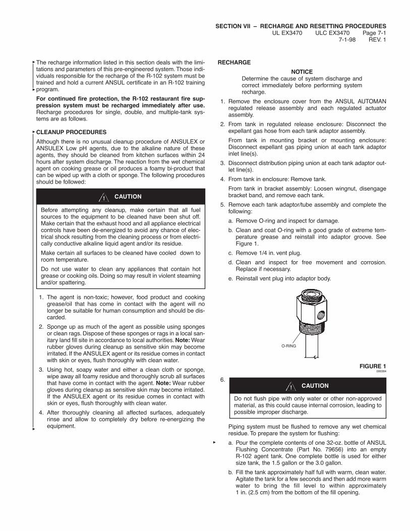
SECTION VII – RECHARGE AND RESETTING PROCEDURESUL EX3470 ULC EX3470 Page 7-1
7-1-98 REV. 1
The recharge information listed in this section deals with the limi-tations and parameters of this pre-engineered system. Those indi-viduals responsible for the recharge of the R-102 system must betrained and hold a current ANSUL certificate in an R-102 trainingprogram.
For continued fire protection, the R-102 restaurant fire sup-pression system must be recharged immediately after use.Recharge procedures for single, double, and multiple-tank sys-tems are as follows.
CLEANUP PROCEDURES
Although there is no unusual cleanup procedure of ANSULEX orANSULEX Low pH agents, due to the alkaline nature of theseagents, they should be cleaned from kitchen surfaces within 24hours after system discharge. The reaction from the wet chemicalagent on cooking grease or oil produces a foamy bi-product thatcan be wiped up with a cloth or sponge. The following proceduresshould be followed:
1. The agent is non-toxic; however, food product and cookinggrease/oil that has come in contact with the agent will nolonger be suitable for human consumption and should be dis-carded.
2. Sponge up as much of the agent as possible using spongesor clean rags. Dispose of these sponges or rags in a local san-itary land fill site in accordance to local authorities. Note: Wearrubber gloves during cleanup as sensitive skin may becomeirritated. If the ANSULEX agent or its residue comes in contactwith skin or eyes, flush thoroughly with clean water.
3. Using hot, soapy water and either a clean cloth or sponge,wipe away all foamy residue and thoroughly scrub all surfacesthat have come in contact with the agent. Note: Wear rubbergloves during cleanup as sensitive skin may become irritated.If the ANSULEX agent or its residue comes in contact withskin or eyes, flush thoroughly with clean water.
4. After thoroughly cleaning all affected surfaces, adequatelyrinse and allow to completely dry before re-energizing theequipment.
RECHARGE
NOTICEDetermine the cause of system discharge andcorrect immediately before performing systemrecharge.
1. Remove the enclosure cover from the ANSUL AUTOMANregulated release assembly and each regulated actuatorassembly.
2. From tank in regulated release enclosure: Disconnect theexpellant gas hose from each tank adaptor assembly.
From tank in mounting bracket or mounting enclosure:Disconnect expellant gas piping union at each tank adaptorinlet line(s).
3. Disconnect distribution piping union at each tank adaptor out-let line(s).
4. From tank in enclosure: Remove tank.
From tank in bracket assembly: Loosen wingnut, disengagebracket band, and remove each tank.
5. Remove each tank adaptor/tube assembly and complete thefollowing:
a. Remove O-ring and inspect for damage.
b. Clean and coat O-ring with a good grade of extreme tem-perature grease and reinstall into adaptor groove. SeeFigure 1.
c. Remove 1/4 in. vent plug.
d. Clean and inspect for free movement and corrosion.Replace if necessary.
e. Reinstall vent plug into adaptor body.
FIGURE 1000364
6.
Piping system must be flushed to remove any wet chemicalresidue. To prepare the system for flushing:
a. Pour the complete contents of one 32-oz. bottle of ANSULFlushing Concentrate (Part No. 79656) into an emptyR-102 agent tank. One complete bottle is used for eithersize tank, the 1.5 gallon or the 3.0 gallon.
b. Fill the tank approximately half full with warm, clean water.Agitate the tank for a few seconds and then add more warmwater to bring the fill level to within approximately1 in. (2.5 cm) from the bottom of the fill opening.
CAUTION!
Do not flush pipe with only water or other non-approvedmaterial, as this could cause internal corrosion, leading topossible improper discharge.
CAUTION!
Before attempting any cleanup, make certain that all fuelsources to the equipment to be cleaned have been shut off.Make certain that the exhaust hood and all appliance electricalcontrols have been de-energized to avoid any chance of elec-trical shock resulting from the cleaning process or from electri-cally conductive alkaline liquid agent and/or its residue.
Make certain all surfaces to be cleaned have cooled down toroom temperature.
Do not use water to clean any appliances that contain hotgrease or cooking oils. Doing so may result in violent steamingand/or spattering.
O-RING
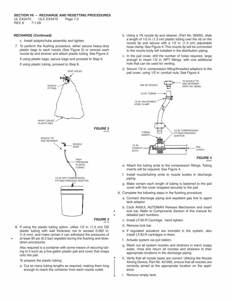
SECTION VII – RECHARGE AND RESETTING PROCEDURESUL EX3470 ULC EX3470 Page 7-2REV. 6 7-1-09
RECHARGE (Continued)
c. Install adaptor/tube assembly and tighten.
7. To perform the flushing procedure, either secure heavy-dutyplastic bags to each nozzle (See Figure 2) or remove eachnozzle tip and strainer and attach plastic tubing. See Figure 3.
If using plastic bags, secure bags and proceed to Step 9.
If using plastic tubing, proceed to Step 8.
FIGURE 2001739
FIGURE 3001740
8. If using the plastic tubing option, utilize 1/2 in. (1.3 cm) ODplastic tubing with wall thickness not to exceed 0.062 in.(1.6 mm), and make certain it can withstand the pressures ofat least 90 psi (6.2 bar) expelled during the flushing and blow-down procedures.
Also required is a container with some means of securing tub-ing to it such as a five-gallon plastic pail and cover that snapsonto the pail.
To prepare the plastic tubing:
a. Cut as many tubing lengths as required, making them longenough to reach the container from each nozzle outlet.
b. Using a 1N nozzle tip and retainer, (Part No. 56930), slidea length of 1/2 in. (1.3 cm) plastic tubing over the rib on thenozzle tip and secure with a 1/2 in. (1.3 cm) adjustablehose clamp. See Figure 4. This nozzle tip will be connectedto the nozzle body left installed in the distribution piping.
c. In the pail cover, drill the number of holes required, largeenough to insert 1/2 in. NPT fittings, with one additionalhole that can be used for venting.
d. Secure 1/2 in. compression fitting/threaded adaptors to thepail cover, using 1/2 in. conduit nuts. See Figure 4.
FIGURE 4000367
e. Attach the tubing ends to the compression fittings. Tubinginserts will be required. See Figure 4.
f. Install nozzle/tubing ends to nozzle bodies in dischargepiping.
g. Make certain each length of tubing is fastened to the pailcover with the cover snapped securely to the pail.
9. Complete the following steps in the flushing procedure:
a. Connect discharge piping and expellant gas line to agenttank adaptor.
b. Cock ANSUL AUTOMAN Release Mechanism and insertlock bar. Refer to Components Section of this manual fordetailed part numbers.
c. Install LT-30-R Cartridge; hand tighten.
d. Remove lock bar.
e. If regulated actuators are included in the system, alsoinstall LT-30-R cartridges in them.
f. Actuate system via pull station.
g. Wash out all system nozzles and strainers in warm soapywater, rinse and return all nozzles and strainers to theirappropriate locations in the discharge piping.
h. Verify that all nozzle types are correct. Utilizing the NozzleAiming Device, Part No. 431992, ensure that all nozzles arecorrectly aimed at the appropriate location on the appli-ance.
i. Remove empty tank.
VENT HOLES
NOZZLEFITTING
HEAVY GAUGEPLASTIC BAG
NOZZLE TIPAND RETAINER
NOZZLEBODY
HIGHPRESSUREPLASTICTUBING
1/2 IN. NPT COMPRESSIONFITTING/THREADED ADAPTOR
RIB ON NOZZLE
1/2 IN. TUBING
1/2 IN. ADJUSTABLEHOSE CLAMP
1N NOZZLE TIPAND RETAINER(PART NO. 56930)
1/2 IN. COMPRESSIONFITTING/THREADEDADAPTOR
TUBINGINSERT
1/2 IN.CONDUITNUTS
PAILCOVER

SECTION VII – RECHARGE AND RESETTING PROCEDURESUL EX3470 ULC EX3470 Page 7-3
7-1-09 REV. 5
RECHARGE (Continued)
10. Fill each tank with 1.5 (5.8 L) or 3.0 (11.6 L) gallons of onlyANSULEX Low pH Liquid Fire Suppressant. Note: Use a fun-nel with a screen to stop any foreign material from entering thetank. See Page 5-2.1, Figure 6, for detailed fillinginstructions.
11. Replace bursting disc, Part No. 416974, in adaptor assembly.Make certain silver side of disc is away from tank.
12. Replace adaptor/tube assembly and tighten into place. Returnand secure each tank in regulated release assembly andmounting bracket/enclosure. Reconnect expellant gas and dis-tribution piping and/or as required.
13. Raise tension lever to “UP” position.
14. Cock regulated release mechanism using cocking lever (PartNo. 14995 or 435603) and install lock bar (Part No. 14985).
15. Remove empty cartridge from regulated release assemblyand each regulated actuator assembly as required.
16. Install properly-rated fusible links in all detectors except theterminal detector.
NOTICEIf actuation was caused by a fire situation, allfusible links must be replaced.
17. Install test link (Part No. 15751) in terminal detector.
18. Lower tension lever to “DOWN” position.
19. Remove the lock bar.
20. Using wire cutter, cut the test link at the terminal detector tosimulate automatic actuation.
NOTICEIf regulated release mechanism does not actu-ate, refer to Steps 2 and 3 of the “TestingDetection System” portion of the “Testing andPlacing In Service” section, Page 6-3, of thismanual.
21. After successful actuation, raise the tension lever to “UP”position.
22. Install properly-rated, ANSUL approved, fusible link in terminaldetector.
23. Cock the regulated release mechanism and install lock bar(Part No. 14985).
24. Locate detector linkage and correctly position in each bracket.
25. Lower tension lever to “DOWN” position.
26. Inspect the base of the wire rope clamping device to makecertain there is a minimum of 1/4 in. (6.4 mm) to a maximumof 3/8 in. (9.5 mm) clearance between the base of the triphammer assembly and the cable lever assembly.
NOTICEIf clearance is not 1/4 in. (6.4 mm) minimum toa maximum of 3/8 in. (9.5 mm), raise tensionlever to “UP” position, raise trip hammer 3/8-1/2 in. (9.5-12.7 mm), tighten set screws, andrepeat Steps 25 and 26.
27. Remove lock bar.
28. Manually test the regulated release mechanism by operatingthe remote manual pull station.
29. Recock the regulated release mechanism and insert the lockbar.
30. Reset all devices which were affected by the system actua-tion. Refer to “Resetting” section, Page 7-3 and 7-4.
RESETTING
Resetting Remote Manual Pull Station
Metal Stamped Style (Part No. 4835 and 54011)
Reset each remote manual pull station by completing the followingsteps:
1. If necessary, remove set screw that is retaining the breakglass rod.
2. If necessary, carefully remove any remaining broken glassfrom station.
3. Press and position ring handle in proper location against coverand slide the replacement glass break rod (Part No. 4834)through stud and handle.
4. Tighten set screw into stud.
5. If no other resetting is required, refer to “CartridgeReplacement,” Page 7-4, and complete steps 1 through 5.
Molded Composite Style (Part No. 415255)
1. Position pull ring in vertical groove of pull station cover.
2. Insert break-away seal, Part No. 79029, through holes in coverand snap in place.
Molded Composite Style with Side Shields (Part No. 434618and 435960)
1. If necessary, carefully remove any remaining broken glassfrom station.
2. Insert the break rod into the two holes toward the top of thepull knob.
3. Pull the excess slack back into the ANSUL AUTOMANRelease. This will pull the pull knob assembly in place.
NOTICETake care in snapping in the ends of the breakrod into the pull station side shields while rotat-ing the entire assembly.
4. Hold the pull knob assembly against the faceplate. Rotate thepull knob assembly counterclockwise until the break rod andpull knob snap in place.
5. Snap the PULL tab onto the pull knob so it is legible.
6. If no other resetting is required, refer to “CartridgeReplacement,” Page 7-4, and complete steps 1 through 5.
CAUTION!
Do not install replacement cartridge at this time or systemmay be actuated.
CAUTION!
During filling, the agent temperature should be 60 °F to80 °F (16 °C to 27 °C). DO NOT FILL WITH COLDAGENT. DO NOT OVERFILL. Overfilling may result inagent entering gas hose and regulator potentially causingsystem malfunction.

SECTION VII – RECHARGE AND RESETTING PROCEDURESUL EX3470 ULC EX3470 Page 7-4REV. 3 7-1-09
RESETTING (Continued)
Resetting Mechanical Gas Shut-Off Valve
Reset each mechanical gas shut-off valve by completing the fol-lowing steps:
1. Remove side cover from gas valve housing.
2. Extend air cylinder rod to full “UP” position. Air cylinder islocated inside the regulated release assembly enclosure.
3. Recock gas valve by pulling valve stem up so pin in stemengages in cocking lever.
4. Check burners for gaseous odor. IF GASEOUS ODOREXISTS, MANUALLY PUSH THE AIR CYLINDER ROD TOTHE FULL “DOWN” POSITION IMMEDIATELY. This willcause the mechanical gas valve to shut the gas line off.
Open any doors and/or windows to clear the area of gaseousfumes, then correct the gas leak before proceeding any fur-ther.
5. If no gaseous odor exists, pilot light may be ignited at this time.
6. Reinstall side cover to gas valve housing. On ANSUL typevalve, make certain roll pin is positioned within both sides ofthe valve housing slot and secure visual inspection seal (PartNo. 197).
7. If no other resetting is required, refer to “CartridgeReplacement” and complete steps 1 through 5.
Resetting Electrical Switch (Snap-Action)
Reset the electric (snap-action) switch by completing the followingsteps:
1. Make certain the power source is on.
2. Electric (snap-action) switch is reset automatically when theregulated release mechanism is recocked.
3. If no other resetting is required, refer to “Cartridge Replace-ment” and complete steps 1 through 5.
Resetting Electrical Gas Shut-Off Valve
Reset each electric gas shut-off valve by completing the followingsteps:
1. Make certain the power source is on.
2. Depress reset button on manual reset relay (red light on). Gasvalve will resume its normal operating (open) position.
3. Check burners for gaseous odor. IF GASEOUS ODOREXISTS, TURN OFF POWER SOURCE IMMEDIATELY. Thiswill cause the electric gas valve to shut the gas line off.
Open any doors and/or windows to clear the area of gaseousfumes, then correct the gas leak before proceeding anyfurther.
4. If no gaseous odor exists, pilot light may be ignited at this time.
5. If no other resetting is required, refer to “Cartridge Replace-ment” and complete steps 1 through 5.
Resetting Pressure Switch
Reset the pressure switch by completing the following:
1. Depress the reset button(s) on the pressure switch cover. Thepressure switch assembly(ies) is located on the right side ofthe regulated release enclosure. An audible click will be heardto verify the pressure switch has resumed its normal (non-actuated) condition.
2. If no other resetting is required, refer to “Cartridge Replace-ment” and complete steps 1 through 5.
REPLACEMENT CARTRIDGE
To complete the recharge and resetting procedures:
1. Remove shipping cap and weigh replacement cartridge.Replace if weight is 1/2 ounce (14.2 g), or more, below weightstamped on cartridge.
2. Make certain regulated release mechanism is cocked and lockbar is installed. Then, install replacement cartridge into theregulated release assembly and each regulated actuatorreceiver and hand tighten.
3. Remove lock bar.
4. Snap cover on regulated release and each regulated actuatorassembly, insert visual seal (Part No. 197) in upper and lowercover hole and secure.
5. Record recharge date on tag attached to unit and/or in a per-manent file.
CAUTION!
To reduce the risk of explosion due to leaking gas, before thegas line is turned on, make certain to extinguish any openflames and turn off all burners and any electrical or mechani-cal devices that are capable of igniting gas.
CAUTION!
To reduce the risk of explosion due to leaking gas, before thegas line is turned on, make certain to extinguish any openflames and turn off all burners and any electrical or mechani-cal devices that are capable of igniting gas.
CAUTION!
Before installing cover, make certain detection tensionlever is secured in the “DOWN” position to enable auto-matic detection and operation of the ANSUL AUTOMANRegulated Release.

SECTION VIII – MAINTENANCE EXAMINATIONUL EX3470 ULC EX3470 Page 8-1
7-1-09 REV. 8
The maintenance information listed in this section deals with thelimitations and parameters of this pre-engineered system. Thoseindividuals responsible for the maintenance of the R-102 systemmust be trained and hold a current ANSUL certificate in an R-102training program.
Maintenance is required semi-annually. At the 12 year interval,along with the normal maintenance exam, the tank(s) must behydro-tested and the regulator(s) must be flow tested.
Prior to performing the required maintenance steps, verify that theR-102 system protection is designed and installed correctly for theexisting appliance and ventilation system configuration. If not,make corrections as required.
SEMI-ANNUAL MAINTENANCE EXAMINATION
Semi-annual maintenance procedures for single, double, andmultiple-tank systems are as follows.
NOTICEUnder certain circumstances hood and ductcleaning operations may render the firesuppression system ineffective due to a coatingof cleaning chemical left on the detection equip-ment or mishandling of the system by cleaningservice personnel. Therefore, it is stronglyrecommended that the R-102 system becompletely inspected and serviced by anauthorized ANSUL distributor immediatelyfollowing any such cleaning operations.
1. Remove the enclosure cover from the ANSUL AUTOMANregulated release assembly and each regulated actuatorassembly.
2. Insert the lock bar (Part No. 14985) on the cocked regulatedrelease mechanism. See Figure 1.
FIGURE 1000321
3. Remove cartridge from regulated release assembly and eachregulated actuator assembly, install safety shipping cap, andset aside in a safe location.
4. Check to make certain the actuation line used to connect theregulated actuator assembly(s) to the ANSUL AUTOMANregulated release assembly is connected to the high pressureside (right side) of the cartridge receiver in the ANSULAUTOMAN and that it is intact, with all fittings securely tight-ened. This includes any 1/8 in. copper tubing and fittings usedto connect to the air cylinder for the ANSUL mechanical gasvalve.
5. To check for leaks in the actuation line, a hand held or electricvacuum pump may be used:
a. Disconnect the actuation line from the ANSUL AUTOMANregulated release cartridge receiver and connect the pumpto the line.
b. The pump should pull a vacuum to 20 inches of mercury, asshown on the gauge. Leaks should not exceed 5 inches ofmercury loss within a 30 second time frame.
c. If the gauge indicates a leak in the line, examine for looseconnections or damage. Repair or replace as needed.
d. If leakage is not due to piping, disassemble the pneumaticactuator assembly(s) in the regulated actuator(s) andinspect the actuator and the O-ring in the actuator. Repairor replace as needed.
Note: Vacuum pumps can be obtained from automotiveparts/supply stores.
Alternate Test Method:
The actuation line can also be pressurized with either CO2 orN2 from a cartridge or with dry air, CO2, or N2 from a largercylinder.
a. Cock the ANSUL AUTOMAN regulated release assemblyand carefully insert Lock Bar, Part No. 14985. See Figure 8.
b. Make certain expellant gas line hose and/or pipe from theregulator in the ANSUL AUTOMAN regulated release isdisconnected from agent storage tanks.
c. Connect Regulator Test Kit, Part No. 56972, to one of theexpellant gas line hoses and securely cap the remaininghose or pipe. See Figure 10.
d. Verify that no cartridges are installed in the ANSULAUTOMAN or the regulated actuator assembly(s).
e. To verify operation of the regulated actuator assembly(s),Pressure Adaptor, Part No. 427560, can be used toconnect to a pressurized CO2 or N2 cylinder, instead ofusing a CO2 or N2 cartridge.
Note: The pressure adaptor assembly comes with a 1/4 in.NPT pipe plug that is required to be installed in the side of theadaptor.
f. Install a suitable 1/4 inch air pressure quick connect fitting(supplied by others) to the bottom of the adaptor.
g. Install and hand tighten the adaptor to the cartridgereceiver and securely attach the corresponding connectorfrom the gas cylinder hose assembly.
h. With the valve on the regulator test kit closed, remove thelock bar and operate the remote cable operated pull stationto operate the regulated release.
i. Open the pressure cylinder valve to verify that the regu-lated actuator assembly(s) has operated properly and theair cylinder has unlatched the ANSUL mechanical gasvalve, if used.
LOCK BARPROPERLYINSTALLED
CAUTION!
If the actuation line leaks pressure, the regulated actuatorassembly(s) may not operate. A severe leak can renderthe entire system inoperable.

SECTION VIII – MAINTENANCE EXAMINATIONUL EX3470 ULC EX3470 Page 8-2REV. 4 7-1-09
SEMI-ANNUAL MAINTENANCE EXAMINATION (Continued)
j. Once regulated actuator and gas valve operation is veri-fied, close the valve on the pressurized cylinder, if used,and open the valve on the regulator test kit to relieve anyresidual pressure.
Note: Although only required at 12 year intervals, the regula-tor in the ANSUL AUTOMAN regulated release can also beverified. See Maintenance steps on page 8-6.
k. Re-cock the ANSUL AUTOMAN regulated release andremove the spent cartridge or pressure adaptor from thecartridge receiver.
l. If there were leaks in the actuation line or in the 1/8 inchcopper gas tubing for the air cylinder(s), re-tighten thefittings or replace damaged components.
m. If the cartridge puncture pin in the regulated actuator(s) didnot fully extend, dismantle the actuator and inspect compo-nents of the actuator assembly.
• Once the pneumatic actuator is disassembled, removethe actuator piston assembly and check the interior wallsof the actuator body for signs of damage or corrosion.
• Check the o-ring for elasticity or cuts. Replace, if neces-sary. Clean and coat o-ring with a good grade of extremetemperature silicone grease and reinstall.
• Re-assemble the actuator assembly(s), and reconnect allactuation and all expellant piping or hose.
6. Remove gasket from cartridge receiver in regulated releasemechanism and each regulated actuator. Check gasket forelasticity or cuts and replace if necessary. Clean and coatgasket lightly with a good grade of extreme temperaturegrease. Reinstall gasket into cartridge receiver(s).
7. From tank in regulated release assembly: Disconnect theexpellant gas hose from each tank adaptor assembly.
From tank in bracket/enclosure assembly: Disconnect theexpellant gas piping union at each tank adaptor inlet line.
8. Disconnect distribution piping union at each tank adaptoroutlet line.
9. From tank in enclosure: Remove tank. Keep in upright positionto avoid spilling the agent.
From tank in bracket assembly: Loosen wingnut, disengagebracket band, and remove each tank. Keep tank in uprightposition to avoid spilling the agent.
10. Remove tank adaptor/tube assembly from each tank. SeeFigure 2.
FIGURE 2000291
11. Make certain that each tank is filled with 1.5 (5.8 L) or 3.0(11.6 L) gallons of only ANSULEX Low pH Liquid FireSuppressant. Fill level to be ONLY to the level indicated in the“Installation” section. See Page 5-2.1, Figure 6, for detailedfilling tolerances.
12. Examine threads on each tank adaptor and tank collar fornicks, burrs, or cross-threading. Clean and coat O-ring with agood grade of extreme temperature grease. See Figure 3.Remove 1/4 in. vent plug and clean and inspect for free move-ment and corrosion (replace if necessary). Reinstall vent plug.Make certain bursting disc is in place and silver side is awayfrom tank. Clean seating surface and return adaptor/tubeassembly to each tank. Tighten securely.
FIGURE 3000364
13. Place fully charged tanks in enclosures and/or brackets andsecure.
14. Carefully assemble and wrench tighten all expellant gas andagent distribution piping.
15. Remove blow-off caps from nozzles. Inspect each blow-off capand replace if deteriorated. On older style metal blow-off caps,make certain spring clip rotates freely on cap. On newer metalblow-off caps, make certain integral O-ring is intact andundamaged. Replace cap(s) if necessary.
NOTICERubber blow-off caps that have been installed inthe system for one year or more must bereplaced.
16. Verify that all nozzle types are correct. Check all nozzles toensure that they are free of cooking grease build-up and havea thin coating of clean silicone grease across the orifice.
Note: Do not allow silicone grease to enter nozzle orifice.
Note: If there is any evidence of cooking grease or otherresidue in the nozzles or distribution piping or agent or agentresidue in the distribution piping, the entire piping networkmust be inspected and thoroughly cleaned. Portions of pipingthat cannot be thoroughly cleaned must be replaced.
Utilizing the Nozzle Aiming Device, Part No. 431992, ensurethat all nozzles are correctly aimed at the appropriate locationon the appliance. Reinstall blow-off caps.
17. Remove the lock bar and manually test the regulated releaseassembly by operating the remote manual pull station. Checkpull station cover for damage or wear. Replace cover if cablehas worn a groove in the cover as deep as the diameter of thecable. If flexible conduit is used in installation, check conduitfor damage, cuts and sharp bends.
O-RING
SILVER SIDE OF DISCAWAY FROM TANK

SECTION VIII – MAINTENANCE EXAMINATIONUL EX3470 ULC EX3470 Page 8-3
7-1-09 REV. 5
SEMI-ANNUAL MAINTENANCE EXAMINATION (Continued)
18. Cock the regulated release mechanism using cocking lever(Part No. 14995 or 435603). See Figure 4.
Before proceeding with Step 18, test electric (snap-action)switches:
a. With the ANSUL AUTOMAN in the cocked or ready posi-tion, press the lever of each switch up. If the switch isworking properly, there should be an audible click.
b. With the ANSUL AUTOMAN in the fired position, press thelever of each switch up, there should be no audible click.
c. If an audible click is heard in the fired position severaladjustments can be made. The trip lever extension pin canbe rotated so the peak of one of the hex points is pointedup against the switch levers.Tighten it in that position. If thisdoesn’t resolve the problem, loosen the screws holding theswitches, apply a small counterclockwise torque on theswitches and retighten the screws. If necessary, a finaladjustment can be made by removing the snap actionswitch and bending the lever slightly.
d. After adjustments, repeat Steps a. and b. Then, recockANSUL AUTOMAN and insert lock bar.
FIGURE 4000320
19. Raise tension lever to “UP” position. See Figure 5.
TENSION LEVERIN “UP” POSITION
FIGURE 5000322
20. Install test link (Part No. 15751) in terminal detector.
21. Lower tension lever to “DOWN” position. See Figure 6.
TENSION LEVERIN “DOWN” POSITION
FIGURE 6001096
22. Using wire cutter, cut test link at terminal detector to simulateautomatic actuation.
NOTICEIf regulated release mechanism does notactuate, refer to Steps 2 and 3 of “TestingDetection System” in “Testing and Placing inService,” Section 6, Page 6-3.
23. After successful actuation, raise the tension lever to “UP”position.
24. Remove and destroy all existing fusible links from the terminaland series detector brackets and replace with properly-ratedANSUL approved, fusible links in accordance with NFPA 17A.

SECTION VIII – MAINTENANCE EXAMINATIONUL EX3470 ULC EX3470 Page 8-4REV. 6 7-1-09
SEMI-ANNUAL MAINTENANCE EXAMINATION (Continued)
25. Inspect wire rope at all detector locations, pulley elbows,pulley tee and at ANSUL AUTOMAN release. If wire ropeshows signs of wear or fraying, replace entire length.
26. Lower the tension lever to “DOWN” position.
27. Recock the regulated release mechanism and insert the lockbar.
28. Inspect the base of the wire rope locking clamp to makecertain that there is a minimum of 1/4 in. (6.4 mm) and amaximum of 3/8 in. (9.5 mm) clearance between the base ofthe trip hammer locking clamp assembly and the cable leverassembly. See Figure 7.
FIGURE 7000329
NOTICEIf clearance is not between 1/4 in. (6.4 mm) or3/8 in. (9.5 mm), raise tension lever to “UP” posi-tion, raise trip hammer 3/8-1/2 in. (9.5-12.7 mm), tighten set screws, and repeat Steps24 and 26.
29. For “scissor” style linkage, locate linkage and properly positionin each bracket all the way toward termination end of detectionrun.
30. If a mechanical gas valve is installed, begin the test procedureby removing both side covers.
31. At the regulated release, push the air cylinder rod fully down.
32. The gas valve should operate.
33. Pull the air cylinder rod to its fully extended position.
34. Re-cock the gas valve by pulling the valve stem up until the pinin the stem engages the cocking lever.
35. Reinstall side covers on the gas valve and connect the visualindication seal.
36. Test electric switches and electric gas valves by completingsteps on Page 6-2 in Section 6, “Testing and Placing InService.”
37. Before reinstalling cartridge, reset all additional equipment byreferring to appropriate section of “Recharge and ResettingProcedures,” Section 7.
38. Remove shipping cap and weigh each cartridge. Replace ifweight is 1/2 ounce (14.2 g), or more, below weight stampedon cartridge.
39. Make certain regulated release mechanism is cocked and lockbar is installed, then screw replacement cartridge into regu-lated release mechanism and each regulated actuatorreceiver(s) and hand tighten.
40. Remove lock bar.
41. Snap cover on regulated release and each regulated actuator,insert visual seal (Part No. 197) through holes in cover andbox, and secure.
42. If system contains an Agent Distribution Hose and RestrainingCable Assembly, also perform the following steps:
a. Carefully pull or push out the appliance and verify that theRestraining Cable limits the travel of the appliance andprevents the application of any pull force or bending stresson the Agent Distribution Hose or hose-to-pipe connec-tions.
b. Check the Restraining Cable to verify it is not frayed and issecurely fastened to the appliance and the wall or restrain-ing location.
c. Check the hose and hose fittings and verify that the hoseremains in a vertical natural loop with no noticeable fatigueat hose end couplings, no hose twists, no hose kinking orsharp bends.
d. Check the outer hose covering for signs of damage, check-ing, tears, or wear. If any of these signs are observed,replace the hose.
e. Return the appliance to its normal operating position.Again, check the hose and hose fittings to verify that thehose does not have sharp bends, and is not kinked,twisted, or caught on anything behind the appliance. If anyof these conditions exist, the hose and/or hose connectionswill require installation modifications.
f. With the appliance in its normal operating position, checkthe hose bend to make certain the bend is not less than a3 in. (7.6 cm) bend radius (6 in. (15.2 cm) diameter). If less,replace hose.
g. Verify that the appliance is returned to its original desiredlocation. Failure to do so may result in undue stress andfatigue of the hose and hose connections.
43. Record semi-annual maintenance date on tag attached to unitand/or in a permanent file.
TRIP HAMMERASSEMBLY
CABLELEVERASSEMBLY
LOCKINGCLAMP
1/4 IN. (6.4 mm)MINIMUM
3/8 IN. (9.5 mm)MAXIMUM
CAUTION!
Make certain tension lever is in the “DOWN” position aftercompleting all tests. Failure to put the tension lever in the“DOWN” position will cause the system to not operateautomatically.

SECTION VIII – MAINTENANCE EXAMINATIONUL EX3470 ULC EX3470 Page 8-5
7-1-09 REV. 5
ANNUAL MAINTENANCE EXAMINATION
In addition to performing all the steps necessary for Semi-AnnualMaintenance, disconnect the agent discharge piping from thestorage tank outlet(s) and verify that the agent distribution pipingis not obstructed.
1. At least annually, use dry air or nitrogen and blow through theagent distribution piping with the nozzle blow-off capsremoved, verifying that dry air or nitrogen is discharging ateach nozzle location.
2. At least annually, all rubber nozzle blow-off caps must bereplaced.
12-YEAR MAINTENANCE EXAMINATION
In addition to performing all of the steps necessary for semi-annualand annual maintenance, the following twelve-year maintenanceprocedures for single, double, and multiple-tank systems must beperformed.
NOTICEUnder certain circumstances hood and duct clean-ing operations may render your fire suppressionsystem ineffective due to a coating of cleaningchemical left on the detection equipment ormishandling of the system by cleaning servicepersonnel.
Therefore, it is strongly recommended that theR-102 system be completely inspected andserviced by an authorized ANSUL distributorimmediately following any such cleaning oper-ations.
At twelve-year intervals, the liquid agent tank(s)must be hydrostatically tested and refilled with afresh charge of ANSULEX Low pH Liquid FireSuppressant. The date of manufacture is stampedon the bottom of the agent tank or on the tank label.
1. Remove the enclosure cover from the ANSUL AUTOMANregulated release assembly and each regulated actuatorassembly.
2. Insert the lock bar (Part No. 14985) on the cocked regulatedrelease mechanism. See Figure 8.
FIGURE 8000321
3. Remove cartridge from regulated release assembly and eachregulated actuator assembly, install safety shipping cap, andset aside in a safe location.
4. Remove gasket from cartridge receiver in regulated releasemechanism and each regulated actuator. Check gasket forelasticity or cuts and replace if necessary. Clean and coatgasket lightly with a good grade of extreme temperaturegrease. Reinstall gasket into cartridge receiver(s).
5. From tank in enclosure: Disconnect the expellant gas piping orhose from each tank adaptor assembly.
From tank in bracket assembly: Disconnect expellant gaspiping union at each tank adaptor inlet line.
6. Disconnect distribution piping union at each tank adaptoroutlet line.
7. From tank in enclosure: Remove tank.
From tank in bracket assembly: Loosen wingnut, disengagebracket band, and remove each tank. Keep tank in uprightposition to avoid spilling the agent.
8. Loosen tank adaptor/tube assembly and remove.
9.
Pour the liquid agent from the tank into a clean, plasticcontainer, and flush tank with clear water.
10. At this point, each liquid agent tank, including the 1/4 in.gas hose assembly, must be HYDROSTATICALLY TESTED to330 psi (26.6 bar). Refer to “Hydrostatic Test Instructions,”F-7602, for test adaptors and instructions.
NOTICEDO NOT hydrostatically test a red painted mildsteel agent storage tank. Instead, replace thetank with a new stainless steel tank shippingassembly (3-Gallon, Part No. 429862, or 1.5Gallon, Part No. 429864).
11. Verify date stamped on cartridge. The cartridge must also behydrotested at intervals not greater than 12 years. (Europeancartridges are not refillable, therefore cannot be hydrotestedand refilled. They must be discarded).
12. If cartridge date indicates the need for hydrotesting, thecartridge must be bled down through normal ANSULAUTOMAN release operation, returned to ANSUL for credit (orhydrotested by properly trained and ANSUL Authorizedcartridge refilling stations), and replaced with a charged,replacement cartridge.
CAUTION!
Do not reinstall cartridge at this time or system may beactuated.
CAUTION!
Safety glasses should be worn during transfer operationsof ANSULEX Low pH Liquid Fire Suppressant. Avoidcontact with skin or eyes. In case of contact, flush imme-diately with water for 15 minutes. If irritation persists,contact a physician. Do not take internally. If taken inter-nally do not induce vomiting. Dilute with water or milk andcontact a physician.
LOCK BARPROPERLYINSTALLED
CAUTION!
If nozzles show signs of cooking grease migration into theorifice of the nozzle, or if there is evidence of agentresidue in the nozzle(s) or the inlet to the agent distribu-tion piping, some or all of the piping may require disman-tling to verify that the piping is not obstructed.

SECTION VIII – MAINTENANCE EXAMINATIONUL EX3470 ULC EX3470 Page 8-6REV. 5 7-1-09
12-YEAR MAINTENANCE EXAMINATION (Continued)
NOTICECartridge bleed down can be used to verifypneumatic accessories operation.
13. If system contains an Agent Distribution Hose and RestrainingCable Assembly, a hydrostatic test is required at 220 psi (15.2bar) for hose assembly.
14. The regulator must be flow tested at 12 year intervals. Checkthe date code stamped on the regulator body to determine ifthe regulator(s) requires the 12 year testing (see data codetable). If regulator does not require testing, proceed to step 12.Flow test the regulator(s) per the following:
Date Code TableCode Code
Month Code Year UL 541L UL 74FF_____ ____ ___ _______ _______
January A 1981 KFebruary B 1982 LMarch C 1983 MApril D 1984 NMay E 1985 PJune F 1986 RJuly G 1987 SAugust H 1988 TSeptember J 1989 UOctober K 1990 VNovember L 1991 WDecember M 1992 Y
1993 Z1994 A1995 B1996 C1997 D1998 E1999 F2000 G2001 H2002 J2003 K2004 L2005 M E2006 F2007 G2008 H2009 I2010 J2011 K2012 L2013 M2014 N2015 O
a. Regulated Release Mechanism
For First Tank: Disconnect expellant gas pipe or hose fromtank. Connect regulator test kit (Part No. 56972) to hose.See Figure 9.
FIGURE 9000369
For Second Tank: Disconnect expellant gas piping at union.Remove union from expellant gas piping and install pipecap to prevent cartridge pressure from escaping duringtest. See Figure 10.
FIGURE 10000370
Pressure Switch: If an ANSUL supplied pressure switch isstill in good operating condition, it should remain connectedas part of system maintenance test.
NOTICEFor multiple-tank systems, one test kit (PartNo. 56972) is required for each regulator inthe system.
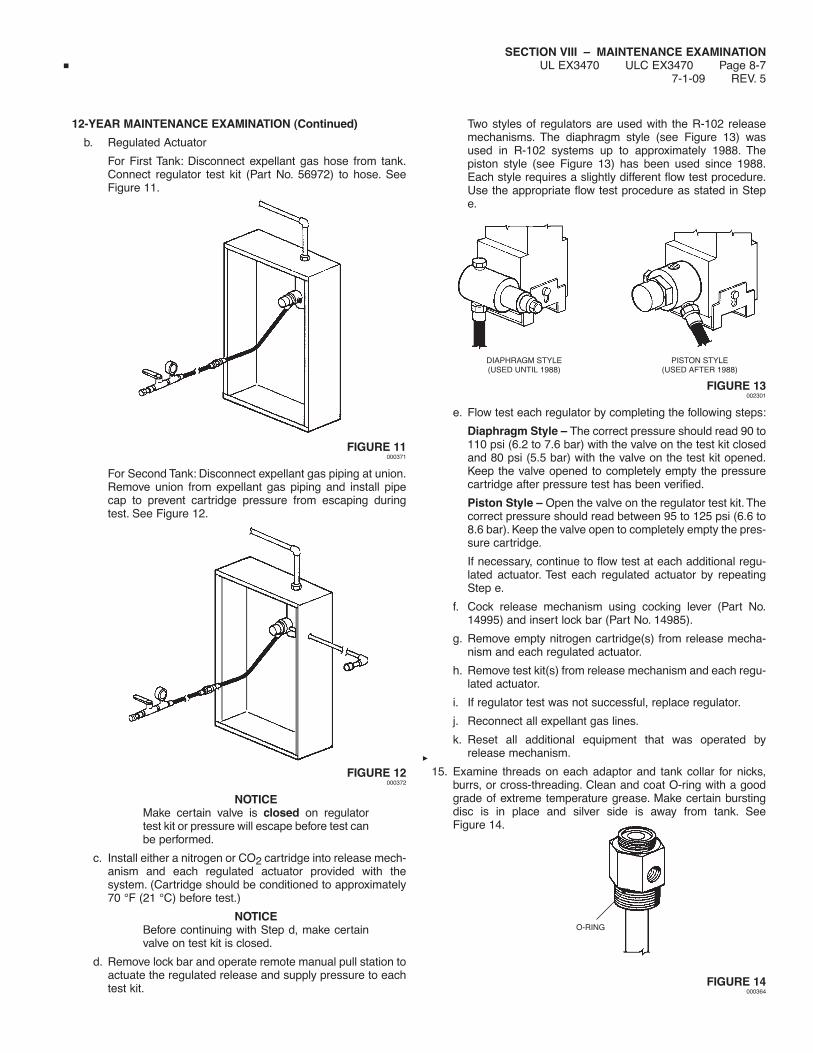
SECTION VIII – MAINTENANCE EXAMINATIONUL EX3470 ULC EX3470 Page 8-7
7-1-09 REV. 5
12-YEAR MAINTENANCE EXAMINATION (Continued)
b. Regulated Actuator
For First Tank: Disconnect expellant gas hose from tank.Connect regulator test kit (Part No. 56972) to hose. SeeFigure 11.
FIGURE 11000371
For Second Tank: Disconnect expellant gas piping at union.Remove union from expellant gas piping and install pipecap to prevent cartridge pressure from escaping duringtest. See Figure 12.
FIGURE 12000372
NOTICEMake certain valve is closed on regulatortest kit or pressure will escape before test canbe performed.
c. Install either a nitrogen or CO2 cartridge into release mech-anism and each regulated actuator provided with thesystem. (Cartridge should be conditioned to approximately70 °F (21 °C) before test.)
NOTICEBefore continuing with Step d, make certainvalve on test kit is closed.
d. Remove lock bar and operate remote manual pull station toactuate the regulated release and supply pressure to eachtest kit.
Two styles of regulators are used with the R-102 releasemechanisms. The diaphragm style (see Figure 13) wasused in R-102 systems up to approximately 1988. Thepiston style (see Figure 13) has been used since 1988.Each style requires a slightly different flow test procedure.Use the appropriate flow test procedure as stated in Stepe.
DIAPHRAGM STYLE PISTON STYLE(USED UNTIL 1988) (USED AFTER 1988)
FIGURE 13002301
e. Flow test each regulator by completing the following steps:
Diaphragm Style – The correct pressure should read 90 to110 psi (6.2 to 7.6 bar) with the valve on the test kit closedand 80 psi (5.5 bar) with the valve on the test kit opened.Keep the valve opened to completely empty the pressurecartridge after pressure test has been verified.
Piston Style – Open the valve on the regulator test kit. Thecorrect pressure should read between 95 to 125 psi (6.6 to8.6 bar). Keep the valve open to completely empty the pres-sure cartridge.
If necessary, continue to flow test at each additional regu-lated actuator. Test each regulated actuator by repeatingStep e.
f. Cock release mechanism using cocking lever (Part No.14995) and insert lock bar (Part No. 14985).
g. Remove empty nitrogen cartridge(s) from release mecha-nism and each regulated actuator.
h. Remove test kit(s) from release mechanism and each regu-lated actuator.
i. If regulator test was not successful, replace regulator.
j. Reconnect all expellant gas lines.
k. Reset all additional equipment that was operated byrelease mechanism.
15. Examine threads on each adaptor and tank collar for nicks,burrs, or cross-threading. Clean and coat O-ring with a goodgrade of extreme temperature grease. Make certain burstingdisc is in place and silver side is away from tank. SeeFigure 14.
FIGURE 14000364
O-RING

SECTION VIII – MAINTENANCE EXAMINATIONUL EX3470 ULC EX3470 Page 8-8REV. 2 7-1-09
12-YEAR MAINTENANCE EXAMINATION (Continued)
16. Examine pick-up tube for signs of damage or corrosion.Replace assembly if needed.
17. Refill each tank with 1.5 (5.8 L) or 3.0 (11.6 L) gallons of onlynew ANSULEX Low pH Liquid Fire Suppressant. Note: Use afunnel with a screen to stop any foreign material from enteringthe tank.
18. Clean seating surface and return each adaptor/tube assemblyto tank. Firmly tighten.
NOTICEDo not reinstall any tank at this time.
19. Remove blow-off caps from nozzles. Inspect each blow-off capand replace if deteriorated. On metal blow-off caps, makecertain spring clip rotates freely on cap.
NOTICERubber blow-off caps that have beeninstalled in the system for one year or moremust be replaced.
20. Check all nozzles to ensure that they are free of cookinggrease build-up and have a covering of clean silicone greaseon the orifice. Reinstall blow-off caps.
21. Remove lock bar and manually test the regulated releaseassembly by operating the remote manual pull station.
22. Cock the regulated release mechanism using cocking lever(Part No. 14995 or 435603). See Figure 15.
FIGURE 15000320
23. Raise the tension lever to “UP” position. See Figure 16.
TENSION LEVERIN “UP” POSITION
FIGURE 16000362
24. Install test link (Part No.15751) in terminal detector.
25. Lower tension lever to “DOWN” position. See Figure 17.
TENSION LEVERIN “DOWN” POSITION
FIGURE 17001096
26. Using wire cutter, cut test link at terminal detector to simulateautomatic actuation.
NOTICEIf regulated release mechanism does notactuate, refer to Steps 2 and 3 of “TestingDetection System” in “Testing and Placing inService,” Section 6.
27. After successful actuation, raise the tension lever to “UP”position.
28. Remove and destroy all existing fusible links from the terminaland series detector brackets and replace with properly-ratedANSUL approved, fusible links in accordance with NFPA 17A.
CAUTION!
During filling, the agent temperature should be 60 °F to80 °F (16 °C to 27 °C). DO NOT FILL WITH COLDAGENT. Refer to the “Installation” section, Page 5-2.1 formaximum fill heights for ANSULEX Low pH agent storagetanks. DO NOT OVERFILL. Overfilling may result in agententering gas hose and regulator, potentially causingsystem malfunction.
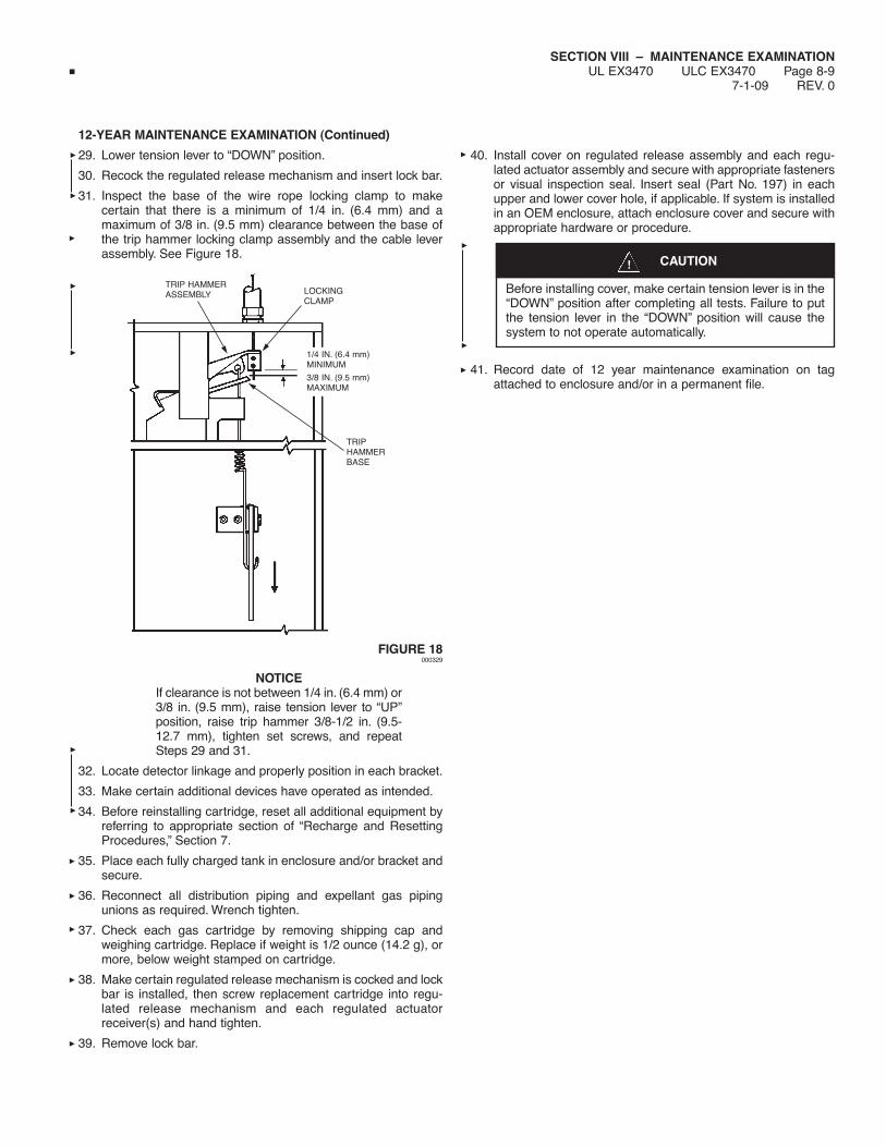
SECTION VIII – MAINTENANCE EXAMINATIONUL EX3470 ULC EX3470 Page 8-9
7-1-09 REV. 0
12-YEAR MAINTENANCE EXAMINATION (Continued)
29. Lower tension lever to “DOWN” position.
30. Recock the regulated release mechanism and insert lock bar.
31. Inspect the base of the wire rope locking clamp to makecertain that there is a minimum of 1/4 in. (6.4 mm) and amaximum of 3/8 in. (9.5 mm) clearance between the base ofthe trip hammer locking clamp assembly and the cable leverassembly. See Figure 18.
FIGURE 18000329
NOTICEIf clearance is not between 1/4 in. (6.4 mm) or3/8 in. (9.5 mm), raise tension lever to “UP”position, raise trip hammer 3/8-1/2 in. (9.5-12.7 mm), tighten set screws, and repeatSteps 29 and 31.
32. Locate detector linkage and properly position in each bracket.
33. Make certain additional devices have operated as intended.
34. Before reinstalling cartridge, reset all additional equipment byreferring to appropriate section of “Recharge and ResettingProcedures,” Section 7.
35. Place each fully charged tank in enclosure and/or bracket andsecure.
36. Reconnect all distribution piping and expellant gas pipingunions as required. Wrench tighten.
37. Check each gas cartridge by removing shipping cap andweighing cartridge. Replace if weight is 1/2 ounce (14.2 g), ormore, below weight stamped on cartridge.
38. Make certain regulated release mechanism is cocked and lockbar is installed, then screw replacement cartridge into regu-lated release mechanism and each regulated actuatorreceiver(s) and hand tighten.
39. Remove lock bar.
40. Install cover on regulated release assembly and each regu-lated actuator assembly and secure with appropriate fastenersor visual inspection seal. Insert seal (Part No. 197) in eachupper and lower cover hole, if applicable. If system is installedin an OEM enclosure, attach enclosure cover and secure withappropriate hardware or procedure.
41. Record date of 12 year maintenance examination on tagattached to enclosure and/or in a permanent file.
TRIP HAMMERASSEMBLY
TRIPHAMMERBASE
LOCKINGCLAMP
1/4 IN. (6.4 mm)MINIMUM
3/8 IN. (9.5 mm)MAXIMUM
CAUTION!
Before installing cover, make certain tension lever is in the“DOWN” position after completing all tests. Failure to putthe tension lever in the “DOWN” position will cause thesystem to not operate automatically.

SECTION VIII – MAINTENANCE EXAMINATIONUL EX3470 ULC EX3470 Page 8-10REV. 0 7-1-09
NOTES:
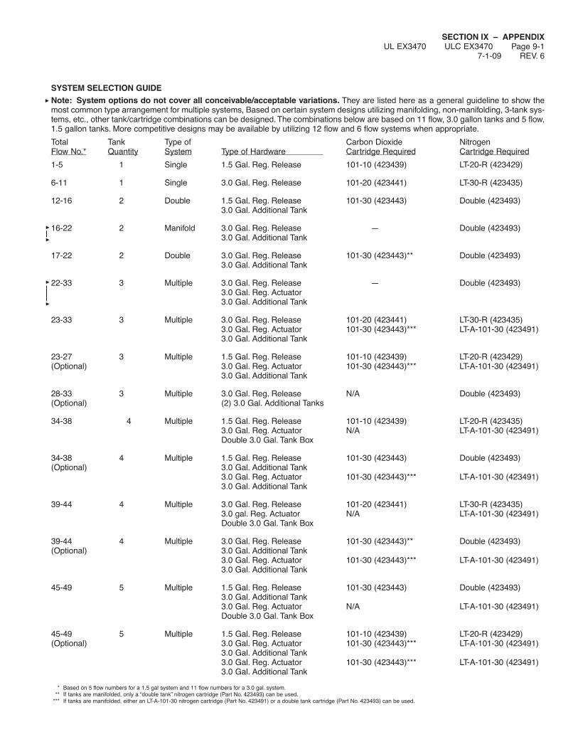
SECTION IX – APPENDIXUL EX3470 ULC EX3470 Page 9-1
7-1-09 REV. 6
SYSTEM SELECTION GUIDENote: System options do not cover all conceivable/acceptable variations. They are listed here as a general guideline to show themost common type arrangement for multiple systems, Based on certain system designs utilizing manifolding, non-manifolding, 3-tank sys-tems, etc., other tank/cartridge combinations can be designed. The combinations below are based on 11 flow, 3.0 gallon tanks and 5 flow,1.5 gallon tanks. More competitive designs may be available by utilizing 12 flow and 6 flow systems when appropriate.
Total Tank Type of Carbon Dioxide NitrogenFlow No.* Quantity System Type of Hardware Cartridge Required Cartridge Required
1-5 1 Single 1.5 Gal. Reg. Release 101-10 (423439) LT-20-R (423429)
6-11 1 Single 3.0 Gal. Reg. Release 101-20 (423441) LT-30-R (423435)
12-16 2 Double 1.5 Gal. Reg. Release 101-30 (423443) Double (423493)3.0 Gal. Additional Tank
16-22 2 Manifold 3.0 Gal. Reg. Release — Double (423493)3.0 Gal. Additional Tank
17-22 2 Double 3.0 Gal. Reg. Release 101-30 (423443)** Double (423493)3.0 Gal. Additional Tank
22-33 3 Multiple 3.0 Gal. Reg. Release — Double (423493)3.0 Gal. Reg. Actuator3.0 Gal. Additional Tank
23-33 3 Multiple 3.0 Gal. Reg. Release 101-20 (423441) LT-30-R (423435)3.0 Gal. Reg. Actuator 101-30 (423443)*** LT-A-101-30 (423491)3.0 Gal. Additional Tank
23-27 3 Multiple 1.5 Gal. Reg. Release 101-10 (423439) LT-20-R (423429)(Optional) 3.0 Gal. Reg. Actuator 101-30 (423443)*** LT-A-101-30 (423491)
3.0 Gal. Additional Tank
28-33 3 Multiple 3.0 Gal. Reg. Release N/A Double (423493)(Optional) (2) 3.0 Gal. Additional Tanks
34-38 4 Multiple 1.5 Gal. Reg. Release 101-10 (423439) LT-20-R (423435)3.0 Gal. Reg. Actuator N/A LT-A-101-30 (423491)Double 3.0 Gal. Tank Box
34-38 4 Multiple 1.5 Gal. Reg. Release 101-30 (423443) Double (423493)(Optional) 3.0 Gal. Additional Tank
3.0 Gal. Reg. Actuator 101-30 (423443)*** LT-A-101-30 (423491)3.0 Gal. Additional Tank
39-44 4 Multiple 3.0 Gal. Reg. Release 101-20 (423441) LT-30-R (423435)3.0 gal. Reg. Actuator N/A LT-A-101-30 (423491)Double 3.0 Gal. Tank Box
39-44 4 Multiple 3.0 Gal. Reg. Release 101-30 (423443)** Double (423493)(Optional) 3.0 Gal. Additional Tank
3.0 Gal. Reg. Actuator 101-30 (423443)*** LT-A-101-30 (423491)3.0 Gal. Additional Tank
45-49 5 Multiple 1.5 Gal. Reg. Release 101-30 (423443) Double (423493)3.0 Gal. Additional Tank3.0 Gal. Reg. Actuator N/A LT-A-101-30 (423491)Double 3.0 Gal. Tank Box
45-49 5 Multiple 1.5 Gal. Reg. Release 101-10 (423439) LT-20-R (423429)(Optional) 3.0 Gal. Reg. Actuator 101-30 (423443)*** LT-A-101-30 (423491)
3.0 Gal. Additional Tank3.0 Gal. Reg. Actuator 101-30 (423443)*** LT-A-101-30 (423491)3.0 Gal. Additional Tank
* Based on 5 flow numbers for a 1.5 gal system and 11 flow numbers for a 3.0 gal. system.** If tanks are manifolded, only a “double tank” nitrogen cartridge (Part No. 423493) can be used.
*** If tanks are manifolded, either an LT-A-101-30 nitrogen cartridge (Part No. 423491) or a double tank cartridge (Part No. 423493) can be used.

SECTION IX – APPENDIXUL EX3470 ULC EX3470 Page 9-2REV. 5 10-1-02
SYSTEM SELECTION GUIDE (Continued)
Total Tank Type of Carbon Dioxide NitrogenFlow No.* Quantity System Type of Hardware Cartridge Required Cartridge Required
50-55 5 Multiple 3.0 Gal. Reg. Release 101-30 (423443) Double (423493)3.0 Gal. Additional Tank3.0 Reg. Actuator N/A LT-A-101-30 (423491)Double 3.0 Gal. Tank Box
50-55 5 Multiple 3.0 Gal. Reg. Release 101-20 (423441) LT-30-R (423435)(Optional) 3.0 Gal. Reg. Actuator 101-30 (423443)*** LT-A-101-30 (423491)
3.0 Gal. Additional Tank3.0 Gal. Reg. Actuator 101-30 (423443)*** LT-A-101-30 (423491)3.0 Gal. Additional Tank
56-60 6 Multiple 1.5 Gal. Reg. Release 101-30 (423443) Double (423493)3.0 Gal. Additional Tank3.0 Gal. Reg. Actuator 101-30 (423443)*** LT-A-101-30 (423491)3.0 Gal. Additional Tank3.0 Gal. Reg. Actuator 101-30 (423443)*** LT-A-101-30 (423491)3.0 Gal. Additional Tank
61-66 6 Multiple 3.0 Gal. Reg. Release 101-30 (423443)** Double (423493)3.0 Gal. Additional Tank3.0 Gal. Reg. Actuator 101-30 (423443)*** LT-A-101-30 (423491)3.0 Gal. Additional Tank3.0 Gal. Reg. Actuator 101-30 (423443)*** LT-A-101-30 (423491)3.0 Gal. Additional Tank
67-71 7 Multiple 1.5 Gal. Reg. Release 101-10 (423439) LT-20-R (423429)(2) 3.0 Gal. Reg. Actuator N/A (2) LT-A-101-30 (423491)(2) Double 3.0 Gal. Tank Box
67-71 7 Multiple Remote Mechanical Release 101-10 (423439) – –(Optional) 3.0 Gal. Reg. Actuator 101-30 (423443) LT-A-101-30 (423491)
1.5 Gal. Additional Tank3.0 Gal. Reg. Actuator 101-30 (423443)*** LT-A-101-30 (423491)3.0 Gal. Additional Tank3.0 Gal. Reg. Actuator 101-30 (423443)*** LT-A-101-30 (423491)3.0 Gal. Additional Tank3.0 Gal. Reg. Actuator 101-20 (423441)*** LT-30-R (423435)
72-77 7 Multiple 3.0 Gal. Reg. Release 101-20 (423441) LT-30-R (423435)(2) 3.0 Gal. Reg. Actuator N/A (2) LT-A-101-30 (423491)(2) Double 3.0 Gal. Tank Box
72-77 7 Multiple Remote Mechanical Release 101-10 (423439) – –(Optional) 3.0 Gal. Reg. Actuator 101-30 (423443)*** LT-A-101-30 (423491)
3.0 Gal. Additional Tank3.0 Gal. Reg. Actuator 101-30 (423443)*** LT-A-101-30 (423491)3.0 Gal. Additional Tank3.0 Gal. Reg. Actuator 101-30 (423443)*** LT-A-101-30 (423491)3.0 Gal. Additional Tank3.0 Gal. Reg. Actuator 101-20 (423441) LT-30-R (423435)
* Based on 5 flow numbers for a 1.5 gal. system and 11 flow numbers for a 3.0 gal. system.** If tanks are manifolded, only a “double tank” nitrogen cartridge (Part No. 423493) can be used.
*** If tanks are manifolded, either an LT-A-101-30 nitrogen cartridge (Part No. 423491) or a double tank cartridge (Part No. 423493) can be used.
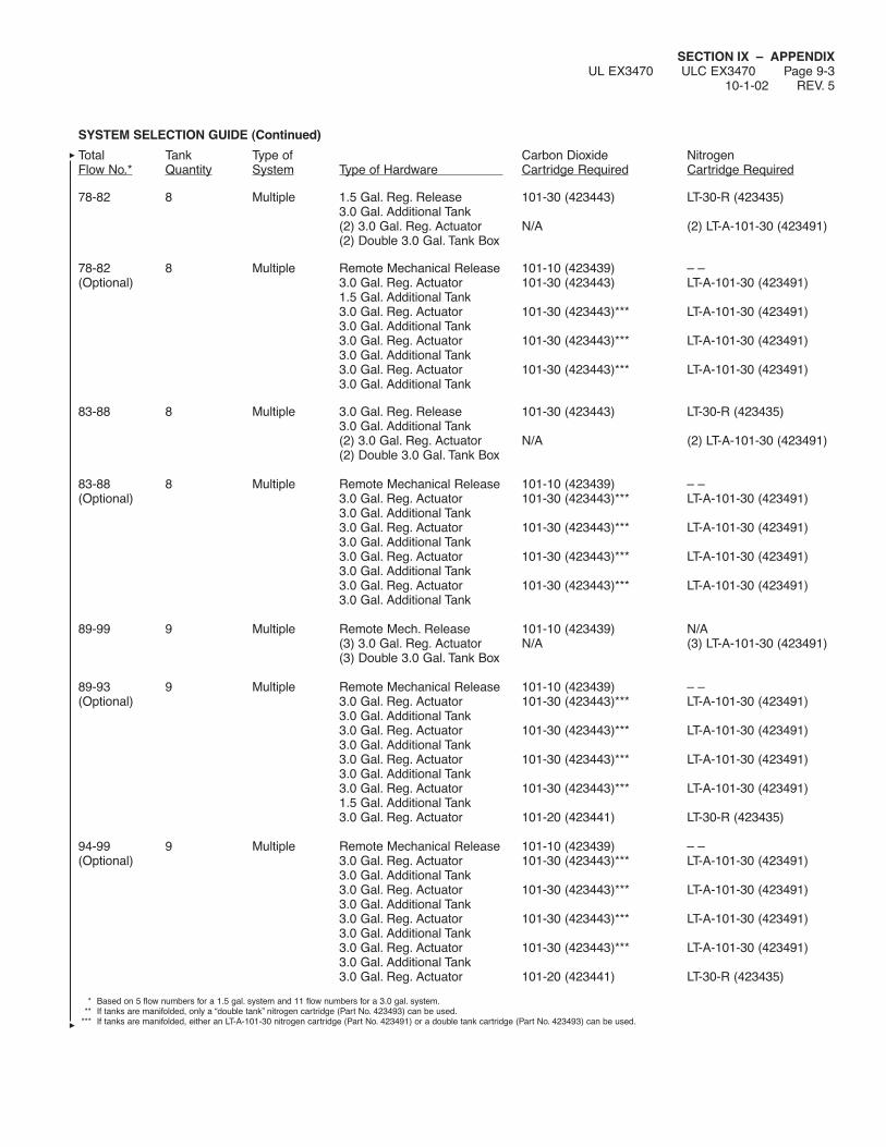
SECTION IX – APPENDIXUL EX3470 ULC EX3470 Page 9-3
10-1-02 REV. 5
SYSTEM SELECTION GUIDE (Continued)
Total Tank Type of Carbon Dioxide NitrogenFlow No.* Quantity System Type of Hardware Cartridge Required Cartridge Required
78-82 8 Multiple 1.5 Gal. Reg. Release 101-30 (423443) LT-30-R (423435)3.0 Gal. Additional Tank(2) 3.0 Gal. Reg. Actuator N/A (2) LT-A-101-30 (423491)(2) Double 3.0 Gal. Tank Box
78-82 8 Multiple Remote Mechanical Release 101-10 (423439) – –(Optional) 3.0 Gal. Reg. Actuator 101-30 (423443) LT-A-101-30 (423491)
1.5 Gal. Additional Tank3.0 Gal. Reg. Actuator 101-30 (423443)*** LT-A-101-30 (423491)3.0 Gal. Additional Tank3.0 Gal. Reg. Actuator 101-30 (423443)*** LT-A-101-30 (423491)3.0 Gal. Additional Tank3.0 Gal. Reg. Actuator 101-30 (423443)*** LT-A-101-30 (423491)3.0 Gal. Additional Tank
83-88 8 Multiple 3.0 Gal. Reg. Release 101-30 (423443) LT-30-R (423435)3.0 Gal. Additional Tank(2) 3.0 Gal. Reg. Actuator N/A (2) LT-A-101-30 (423491)(2) Double 3.0 Gal. Tank Box
83-88 8 Multiple Remote Mechanical Release 101-10 (423439) – –(Optional) 3.0 Gal. Reg. Actuator 101-30 (423443)*** LT-A-101-30 (423491)
3.0 Gal. Additional Tank3.0 Gal. Reg. Actuator 101-30 (423443)*** LT-A-101-30 (423491)3.0 Gal. Additional Tank3.0 Gal. Reg. Actuator 101-30 (423443)*** LT-A-101-30 (423491)3.0 Gal. Additional Tank3.0 Gal. Reg. Actuator 101-30 (423443)*** LT-A-101-30 (423491)3.0 Gal. Additional Tank
89-99 9 Multiple Remote Mech. Release 101-10 (423439) N/A(3) 3.0 Gal. Reg. Actuator N/A (3) LT-A-101-30 (423491)(3) Double 3.0 Gal. Tank Box
89-93 9 Multiple Remote Mechanical Release 101-10 (423439) – –(Optional) 3.0 Gal. Reg. Actuator 101-30 (423443)*** LT-A-101-30 (423491)
3.0 Gal. Additional Tank3.0 Gal. Reg. Actuator 101-30 (423443)*** LT-A-101-30 (423491)3.0 Gal. Additional Tank3.0 Gal. Reg. Actuator 101-30 (423443)*** LT-A-101-30 (423491)3.0 Gal. Additional Tank3.0 Gal. Reg. Actuator 101-30 (423443)*** LT-A-101-30 (423491)1.5 Gal. Additional Tank3.0 Gal. Reg. Actuator 101-20 (423441) LT-30-R (423435)
94-99 9 Multiple Remote Mechanical Release 101-10 (423439) – –(Optional) 3.0 Gal. Reg. Actuator 101-30 (423443)*** LT-A-101-30 (423491)
3.0 Gal. Additional Tank3.0 Gal. Reg. Actuator 101-30 (423443)*** LT-A-101-30 (423491)3.0 Gal. Additional Tank3.0 Gal. Reg. Actuator 101-30 (423443)*** LT-A-101-30 (423491)3.0 Gal. Additional Tank3.0 Gal. Reg. Actuator 101-30 (423443)*** LT-A-101-30 (423491)3.0 Gal. Additional Tank3.0 Gal. Reg. Actuator 101-20 (423441) LT-30-R (423435)
* Based on 5 flow numbers for a 1.5 gal. system and 11 flow numbers for a 3.0 gal. system.** If tanks are manifolded, only a “double tank” nitrogen cartridge (Part No. 423493) can be used.
*** If tanks are manifolded, either an LT-A-101-30 nitrogen cartridge (Part No. 423491) or a double tank cartridge (Part No. 423493) can be used.

SECTION IX – APPENDIXUL EX3470 ULC EX3470 Page 9-4REV. 7 10-1-02
SYSTEM SELECTION GUIDE (Continued)
Total Tank Type of Carbon Dioxide NitrogenFlow No.* Quantity System Type of Hardware Cartridge Required Cartridge Required
100-110 10 Multiple Remote Mech. Release 101-10 (423439) N/A(3) 3.0 Gal. Reg. Actuator N/A (3) LT-A-101-30 (423491)(3) Double 3.0 Gal. Tank Box3.0 Gal. Reg. Actuator 101-20 (423441) LT-30-R (423435)
100-104 10 Multiple Remote Mechanical Release 101-10 (423439) – –(Optional) 3.0 Gal. Reg. Actuator 101-30 (423443) LT-A-101-30 (423491)
1.5 Gal. Additional Tank3.0 Gal. Reg. Actuator 101-30 (423443)*** LT-A-101-30 (423491)3.0 Gal. Additional Tank3.0 Gal. Reg. Actuator 101-30 (423443)*** LT-A-101-30 (423491)3.0 Gal. Additional Tank3.0 Gal. Reg. Actuator 101-30 (423443)*** LT-A-101-30 (423491)3.0 Gal. Additional Tank3.0 Gal. Reg. Actuator 101-30 (423443)*** LT-A-101-30 (423491)3.0 Gal. Additional Tank
100-104 10 Multiple Remote Mech. Release 101-10 (423439) N/A(Optional) (2) 3.0 Gal. Reg. Actuator N/A (2) LT-A-101-30 (423491)
(2) Double 3.0 Gal. Tank Box(2) 3.0 Gal. Reg. Actuator (2) 101-30 (423443) (2) LT-A-101-30 (423491)3.0 Gal. Additional Tank1.5 Gal. Additional Tank
105-110 10 Multiple Remote Mechanical Release 101-10 (423439) – –(Optional) 3.0 Gal. Reg. Actuator 101-30 (423443)*** LT-A-101-30 (423491)
3.0 Gal. Additional Tank3.0 Gal. Reg. Actuator 101-30 (423443)*** LT-A-101-30 (423491)3.0 Gal. Additional Tank3.0 Gal. Reg. Actuator 101-30 (423443)*** LT-A-101-30 (423491)3.0 Gal. Additional Tank3.0 Gal. Reg. Actuator 101-30 (423443)*** LT-A-101-30 (423491)3.0 Gal. Additional Tank3.0 Gal. Reg. Actuator 101-30 (423443)*** LT-A-101-30 (423491)3.0 Gal. Additional Tank
* Based on 5 flow numbers for a 1.5 gal. system and 11 flow numbers for a 3.0 gal. system.** If tanks are manifolded, only a “double tank” nitrogen cartridge (Part No. 423493) can be used.
*** If tanks are manifolded, either an LT-A-101-30 nitrogen cartridge (Part No. 423491) or a double tank cartridge (Part No. 423493) can be used.
Options are available up to a maximum of 15 tanks. Contact ANSUL Technical Services Department for detailed information.

SECTION IX – APPENDIXUL EX3470 ULC EX3470 Page 9-5
7-1-09 REV. 6
SYSTEM COMPONENT INDEX
Part No. Description
429853 Mechanical ANSUL AUTOMAN(ULC Regulated Release Shipping AssemblyAlso) Includes: Regulated Release Mechanism in
Stainless Steel Mounting Enclosure
429856 Electric ANSUL AUTOMANRegulated Release Shipping Assembly
Includes: Regulated Release Mechanism withSolenoid and Switch inStainless Steel Mounting Enclosure
429850 Regulated Actuator Shipping Assembly(ULC Includes: Actuator and Regulator inAlso) Stainless Steel Mounting Enclosure
429870 Stainless Steel Mounting Box Shipping Assembly(ULC Includes: Stainless Steel Mounting BoxAlso)
429872 Two Tank Enclosure Shipping Assembly(ULC Includes: Two (2) Expellant Gas HosesAlso) Two (2) Grommets
Stainless Steel Mounting Box
429859 24 VDC Regulated Release Shipping Assembly(ULC) Includes: 24 VDC ANSUL AUTOMAN II-C
Release Mechanism in Stainless SteelMounting Box
430299 3.0 Gallon Mechanical Release Shipping Assemblyincluding:429853 Mechanical Regulated Release Assembly429862 3.0 Gallon Tank Assembly
430300 1.5 Gallon Mechanical Release Shipping Assemblyincluding
429853 Mechanical Regulated Release Assembly429864 1.5 Gallon Tank Assembly
430309 3.0 Gallon Regulated Actuator Shipping Assemblyincluding:
429850 Regulated Actuator Assembly429862 3.0 Gallon Tank Assembly
430316 1.5 Gallon Stainless Steel Enclosure ShippingAssembly including:
429870 Single Tank Mounting Box Assembly429864 1.5 Gallon Tank Assembly
430317 3.0 Gallon Stainless Steel Enclosure ShippingAssembly including:
429870 Single Tank Mounting Box Assembly429862 3.0 Gallon Tank Assembly
430324 6.0 Gallon Stainless Steel Enclosure ShippingAssembly including:
429872 Two Tank Mounting Box Assembly429862 3.0 Gallon Tank Assembly (2)
430332 3.0 Gallon Mounting Bracket Shipping Assemblyincluding:
429878 3.0 Gallon Mounting Bracket Assembly429862 3.0 Gallon Tank Assembly
Part No. Description
418054 OEM Regulated Electric Release Shipping AssemblyIncludes: Regulated Release Mechanism with
Solenoid and Switch1/4 in. Hose and Mounting Bracket
79493 OEM Regulated Mechanical Release ShippingAssembly
Includes: Regulated Release Mechanism1/4 in. Hose and Mounting Bracket
418691 OEM Regulated Actuator Shipping AssemblyIncludes: Actuator and Regulator
HoseBracket
429878 3.0 Gallon Bracket Assembly(Bracket Only)
433485 Remote Release Assembly
418522 OEM Regulated Actuator Shipping AssemblyIncludes: Actuator and Regulator
Hose
429862 3.0 Gallon Tank Shipping Assembly
429864 1.5 Gallon Tank Shipping Assembly
56972 Regulator Test KitIncludes: Gauge, Hose and Valve Assembly
79694 1.5 Gallon (5.8 L) Container of ANSULEX Low pHLiquid Fire Suppressant
79372 3.0 Gallon (11.6 L) Container of ANSULEX Low pHLiquid Fire Suppressant
423429 Cartridge Shipping Assembly (LT-20-R) (TC/DOT)
423435 Cartridge Shipping Assembly (LT-30-R) (TC/DOT)
423493 Cartridge Shipping Assembly (R-102 Double-Tank)(TC/DOT)
423491 Cartridge Shipping Assembly (LT-A-101-30) (TC/DOT)
423439 Cartridge Shipping Assembly (101-10) (TC/DOT)
15850 Cartridge Shipping Assembly (101-10) (DOT)
423441 Cartridge Shipping Assembly (101-20) (TC/DOT)
423443 Cartridge Shipping Assembly (101-30) (TC/DOT)
428440 Cartridge Shipping Assembly (LT-20-R) (European)
428441 Cartridge Shipping Assembly (LT-30-R) (European)
428446 Cartridge Shipping Assembly (R-102 Double Tank)(European)
428442 Cartridge Shipping Assembly (LT-A-101-30)(European)
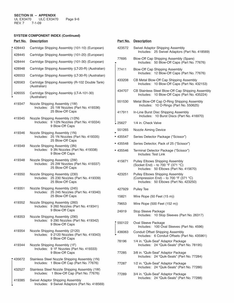
SECTION IX – APPENDIXUL EX3470 ULC EX3470 Page 9-6REV. 7 7-1-09
SYSTEM COMPONENT INDEX (Continued)
Part No. Description
428443 Cartridge Shipping Assembly (101-10) (European)
428445 Cartridge Shipping Assembly (101-20) (European)
428444 Cartridge Shipping Assembly (101-30) (European)
428948 Cartridge Shipping Assembly (LT-20-R) (Australian)
426553 Cartridge Shipping Assembly (LT-30-R) (Australian)
426563 Cartridge Shipping Assembly (R-102 Double Tank)(Australian)
426555 Cartridge Shipping Assembly (LT-A-101-30)(Australian)
419347 Nozzle Shipping Assembly (1W)Includes: 25 1W Nozzles (Part No. 419336)
25 Blow-Off Caps
419345 Nozzle Shipping Assembly (1/2N)Includes: 9 1/2N Nozzles (Part No. 419334)
9 Blow-Off Caps
419346 Nozzle Shipping Assembly (1N)Includes: 25 1N Nozzles (Part No. 419335)
25 Blow-Off Caps
419349 Nozzle Shipping Assembly (3N)Includes: 9 3N Nozzles (Part No. 419338)
9 Blow-Off Caps
419348 Nozzle Shipping Assembly (2W)Includes: 25 2W Nozzles (Part No. 419337)
25 Blow-Off Caps
419350 Nozzle Shipping Assembly (230)Includes: 25 230 Nozzles (Part No. 419339)
25 Blow-Off Caps
419351 Nozzle Shipping Assembly (245)Includes: 25 245 Nozzles (Part No. 419340)
25 Blow-Off Caps
419352 Nozzle Shipping Assembly (260)Includes: 9 260 Nozzles (Part No. 419341)
9 Blow-Off Caps
418353 Nozzle Shipping Assembly (290)Includes: 9 290 Nozzles (Part No. 419342)
9 Blow-Off Caps
419354 Nozzle Shipping Assembly (2120)Includes: 9 2120 Nozzles (Part No. 419343)
9 Blow-Off Caps
419344 Nozzle Shipping Assembly (1F)Includes: 9 1F Nozzles (Part No. 419333)
9 Blow-Off Caps
435672 Stainless Steel Nozzle Shipping Assembly (1N)Includes: 1 Blow-Off Cap (Part No. 77676)
432527 Stainless Steel Nozzle Shipping Assembly (1W)Includes: 1 Blow-Off Cap (Part No. 77676)
419385 Swivel Adaptor Shipping AssemblyIncludes: 9 Swivel Adaptors (Part No. 418569)
Part No. Description
423572 Swivel Adaptor Shipping AssemblyIncludes: 25 Swivel Adaptors (Part No. 418569)
77695 Blow-Off Cap Shipping Assembly (Spare)Includes: 50 Blow-Off Caps (Part No. 77676)
77411 Blow-Off Cap Shipping AssemblyIncludes: 12 Blow-Off Caps (Part No. 77676)
433208 CB Metal Blow-Off Cap Shipping AssemblyIncludes: 10 Blow-Off Caps (Part No. 432153)
434707 CB Stainless Steel Blow-Off Cap Shipping AssemblyIncludes: 10 Blow-Off Caps (Part No. 435224)
551530 Metal Blow-Off Cap O-Ring Shipping AssemblyIncludes: 10 O-Rings (Part No. 550625)
417911 In-Line Burst Disc Shipping AssemblyIncludes: 10 Burst Discs (Part No. 416970)
25627 1/4 in. Check Valve
551265 Nozzle Aiming Device
435547 Series Detector Package (“Scissor”)
435548 Series Detector, Pack of 25 (“Scissor”)
435546 Terminal Detector Package (“Scissor”)Includes: Test Link
415671 Pulley Elbows Shipping Assembly (Socket End) – to 700 °F (371 °C)
Includes: 50 Elbows (Part No. 415670)
423251 Pulley Elbows Shipping Assembly(Compression End) – to 700 °F (371 °C)
Includes: 50 Elbows (Part No. 423250)
427929 Pulley Tee
15821 Wire Rope (50 Feet (15 m))
79653 Wire Rope (500 Feet (152 m))
24919 Stop Sleeve PackageIncludes: 10 Stop Sleeves (Part No. 26317)
550122 Oval Sleeve PackageIncludes: 100 Oval Sleeves (Part No. 4596)
436063 Conduit Offset Shipping AssemblyIncludes: 6 Conduit Offsets (Part No. 435961)
78196 1/4 in. “Quik-Seal” Adaptor PackageIncludes: 24 “Quik-Seals” (Part No. 78195)
77285 3/8 in. “Quik-Seal” Adaptor PackageIncludes: 24 “Quik-Seals” (Part No. 77284)
77287 1/2 in. “Quik-Seal” Adaptor PackageIncludes: 24 “Quik-Seals” (Part No. 77286)
77289 3/4 in. “Quik-Seal” Adaptor PackageIncludes: 24 “Quik-Seals” (Part No. 77288)

SECTION IX – APPENDIXUL EX3470 ULC EX3470 Page 9-6.1
7-1-09 REV. 5
SYSTEM COMPONENT INDEX (Continued)
Part No. Description
79149 1/4 in. “Compression-Seal” Pipe Adaptor PackageIncludes: 24 “Compression-Seals”
(Part No. 79148)
79151 3/8 in. “Compression-Seal” Pipe Adaptor PackageIncludes: 24 “Compression-Seals”
(Part No. 79150)
79147 1/2 in. “Compression-Seal” Pipe Adaptor PackageIncludes: 24 “Compression-Seals”
(Part No. 79146)
79153 1/2 in. “Compression-Seal” EMT Conduit AdaptorPackage
Includes: 24 “Compression-Seals”(Part No. 79152)
423253 Hood Seal Adaptor Shipping AssemblyIncludes: 6 Hood Seals
436228 Reducing Coupling
435603 Short Handle Cocking Lever(Mechanical/Electrical ANSUL AUTOMAN)
435790 Short Handle Cocking Lever with Lock Bar(Mechanical/Electrical ANSUL AUTOMAN)
14995 Long Handle Cocking Lever(Mechanical/Electrical ANSUL AUTOMAN)
15618 Long Handle Cocking Lever with Lock Bar(Mechanical/Electrical ANSUL AUTOMAN)
26310 Cocking Lever (ANSUL AUTOMAN II-C)
416018 Cocking Lever (Mechanical Gas Valve)
14985 Lock Bar
13707 Gas Shut-off Equipment (Electrical 110 VAC, 60 Hz)Includes: Solenoid Valve – 3/4 in.
13708 Gas Shut-off Equipment (Electrical 110 VAC, 60 Hz)Includes: Solenoid Valve – 1 in.
550360 Gas Shut-off Equipment (Electrical 110 VAC, 60 Hz)Includes: Solenoid Valve – 1 1/4 in.
13709 Gas Shut-off Equipment (Electrical 110 VAC, 60 Hz)Includes: Solenoid Valve – 1 1/2 in.
13710 Gas Shut-off Equipment (Electrical 110 VAC, 60 Hz)Includes: Fluid Power Gas Valve – 2 in.
550363 Gas Shut-off Equipment (Electrical 110 VAC, 60 Hz)Includes: Fluid Power Gas Valve – 2 1/2 in.
17643 Gas Shut-off Equipment (Electrical 110 VAC, 60 Hz)Includes: Fluid Power Gas Valve – 3 in.
426151 Gas Shut-off Equipment (Electrical 110 VAC, 60 Hz)Includes: Relay – Manual Reset
423878 One Electric Switch (Field Mounted) KitIncludes: Electric Switch (SPDT),Mounting Hardware
Part No. Description
423879 Two Electric Switch (Field Mounted) KitIncludes: 2 Electric Switches (SPDT),Mounting Hardware
423880 Three Electric Switch (Field Mounted) KitIncludes: 3 Electric Switches (SPDT),Mounting Hardware
423881 Four Electric Switch (Field Mounted) KitIncludes: 4 Electric Switches (SPDT),Mounting Hardware
428311 Alarm Initiating Switch Kit
55598 Gas Shut-off Equipment Mechanical (ANSUL)Includes: Mechanical Gas Valve – 3/4 in.
55601 Gas Shut-off Equipment Mechanical (ANSUL)Includes: Mechanical Gas Valve – 1 in.
55604 Gas Shut-off Equipment Mechanical (ANSUL)Includes: Mechanical Gas Valve – 1 1/4 in.
55607 Gas Shut-off Equipment Mechanical (ANSUL)Includes: Mechanical Gas Valve – 1 1/2 in.
55610 Gas Shut-off Equipment Mechanical (ANSUL)Includes: Mechanical Gas Valve – 2 in.
25937 Gas Shut-off Equipment Mechanical (ASCO)Includes: Mechanical Gas Valve – 2 1/2 in.
25938 Gas Shut-off Equipment Mechanical (ASCO)Includes: Mechanical Gas Valve – 3 in.
15733 Gas Shut-off EquipmentIncludes: Air Cylinder and Tube Assembly
434618 Remote Manual Pull Station Assembly
435960 Remote Manual Pull Station AssemblyIncludes: 50 ft (15.2 m) of Wire Rope
24915 Break Rod PackageIncludes: 10 Glass Break Rods (Part No. 4834)
(Replacement)
427074 Trim Rings (Pack of 10)
434525 Flexible Conduit – 500 ft (152.4 m)
435959 Flexible Conduit – 500 ft (152.4 m)Includes: 500 ft (152.4 m) of Wire Rope
435979 Flexible Conduit Strain ReliefIncludes: 50 Strain Reliefs
434347 Flexible Conduit InsertsIncludes: 50 Inserts
31809 16 in. (41 cm) Stainless Steel Actuation Hose
32335 20 in. (51 cm) Stainless Steel Actuation Hose
32336 24 in. (61 cm) Stainless Steel Actuation Hose
430815 42 in. (107 cm) Stainless Steel Actuation Hose
435982 Agent Distribution Hose and Restraining Cable Kit

SECTION IX – APPENDIXUL EX3470 ULC EX3470 Page 9-6.2REV. 3 7-1-09
SYSTEM COMPONENT INDEX (Continued)
Part No. Description
434455 Henny Penny Fryer Nozzle Kit
423429 Recharge EquipmentIncludes: LT-20-R Cartridge
423435 Recharge EquipmentIncludes: LT-30-R Cartridge
423493 Recharge EquipmentIncludes: Double System Cartridge
423491 Recharge EquipmentIncludes: LT-A-101-30 Cartridge
423439 Recharge EquipmentIncludes: 101-10 Cartridge
423441 Recharge EquipmentIncludes: 101-20 Cartridge
423443 Recharge EquipmentIncludes: 101-30 Cartridge
79372 Recharge EquipmentIncludes: 3.0 Gallon (11.4 L) Container of
ANSULEX Low pH Liquid Fire Suppressant
79694 Recharge EquipmentIncludes: 1.5 Gallon (5.7 L) Container of
ANSULEX Low pH Liquid FireSuppressant
417911 Recharge EquipmentIncludes: Package of 10 Tank Adaptor Bursting
Discs
77695 Recharge EquipmentIncludes: 50 Blow-Off Caps
24916 Recharge EquipmentIncludes: 10 Test Links (Part No. 15751)
415739 Recharge EquipmentIncludes: Fusible Link 165 °F (74 °C)
415740 Recharge EquipmentIncludes: Fusible Link 212 °F (100 °C)
415744 Recharge EquipmentIncludes: 25 Fusible Links 280 °F (138 °C)
(Part No. 415741)
415745 Recharge EquipmentIncludes: 25 Fusible Links 360 oF (182 °C)
(Part No. 415742)
415746 Recharge EquipmentIncludes: 25 Fusible Links 450 °F (232 °C)
(Part No. 415743)
Part No. Description
73867 Recharge EquipmentIncludes: 25 Fusible Links 500 °F (260 °C)
(Part No. 56816)
79651 Recharge EquipmentIncludes: Detector Bracket – “Scissor”
415817 Recharge EquipmentIncludes: Detector Linkage – “Scissor”
14985 Recharge EquipmentIncludes: Lock Bar
14995 Recharge EquipmentIncludes: Cocking Lever
26310 Recharge EquipmentIncludes: Cocking Lever for
ANSUL AUTOMAN II-C
15618 Recharge EquipmentIncludes: Cocking Lever and Lock Bar Assembly
15240 Recharge EquipmentIncludes: 500 °F (260 °C) Exhaust Duct
Thermometer
197 Recharge EquipmentIncludes: Lead and Wire Seal
418087 Recharge EquipmentIncludes: Installation Manual

SECTION IX – APPENDIXUL EX3470 ULC EX3470 Page 9-7
7-1-09 REV. 4
“ANSUL AUTOMAN” REGULATED RELEASE ASSEMBLY
Figure Mechanical ElectricalNo. Description Part No. Part No.
– Regulated Release Shipping Assembly 429853 4298561 Mounting Box 419293 4192932 Basic Release w/Regulator 79140 –
Basic Release w/Solenoid, Switch, and Regulator – 792883 Self-Tapping Screw 71342 713424 Spacer 76555 765555 Tension Spring 79094 790946 Lever and Bracket Assembly 79300 793007 Machine Screw 14973 149738 Lockwasher 7310 73109 Hex Nut 14732 14732
10 Caution Label 57652 5765211 Gasket 181 18112 Expellant Gas Cartridge Assembly
LT-30-R/101-20 (Ordered Separately) 423435/423441 423435/423441Double Tank/101-30 (Ordered Separately) 423493/423443 423443/423443
13 Safety Shipping Cap 77251 7725114 Tank Assembly 1.5/3.0 Gal. (Ordered Separately) 429864/429862 429864/42986215 Hose Assembly 79007 7900716 Enclosure Cover (Includes Label) 423744 42374417 Solenoid Assembly – 42357518 Electric Snap-Action Switch – 42387819 Cover Screw 15362 1536220 Speed Nut 423479 42347921 Set Screw 73101 73101
5
7
21
89
6213
17
10
18
1
14 (ORDEREDSEPARATELY)
15 11
16
000373
19, 20
3
4
12
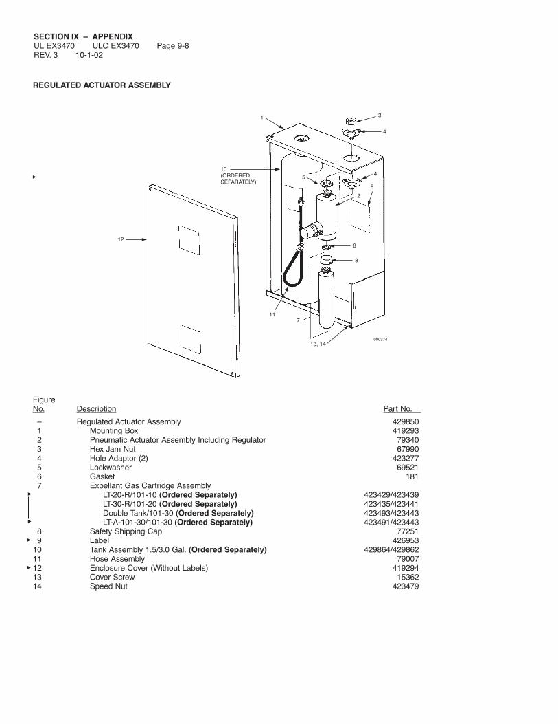
SECTION IX – APPENDIXUL EX3470 ULC EX3470 Page 9-8REV. 3 10-1-02
REGULATED ACTUATOR ASSEMBLY
FigureNo. Description Part No.
– Regulated Actuator Assembly 4298501 Mounting Box 4192932 Pneumatic Actuator Assembly Including Regulator 793403 Hex Jam Nut 679904 Hole Adaptor (2) 4232775 Lockwasher 695216 Gasket 1817 Expellant Gas Cartridge Assembly
LT-20-R/101-10 (Ordered Separately) 423429/423439LT-30-R/101-20 (Ordered Separately) 423435/423441Double Tank/101-30 (Ordered Separately) 423493/423443LT-A-101-30/101-30 (Ordered Separately) 423491/423443
8 Safety Shipping Cap 772519 Label 426953
10 Tank Assembly 1.5/3.0 Gal. (Ordered Separately) 429864/42986211 Hose Assembly 7900712 Enclosure Cover (Without Labels) 41929413 Cover Screw 1536214 Speed Nut 423479
1
2
3
4
45
6
7
8
9
10(ORDEREDSEPARATELY)
11
13, 14000374
12

SECTION IX – APPENDIXUL EX3470 ULC EX3470 Page 9-9
4-1-06 REV. 4
ENCLOSURE ASSEMBLY
FigureNo. Description Part No.
– Enclosure Shipping Assembly 4298701 Enclosure 4192952 Cover 4192963 Nameplate 4298714 Screw 153625 Speed Nut 423479
000290
1
2
3
4
5

SECTION IX – APPENDIXUL EX3470 ULC EX3470 Page 9-10REV. 3 10-1-02
BRACKET ASSEMBLY
Figure 3.0 GallonNo. Description Part No.
– Bracket Shipping Assembly 4298781 Bracket Assembly –2 Grommet 140893 Grommet 86884 Wing Nut 12065
1
2
3
4
000376
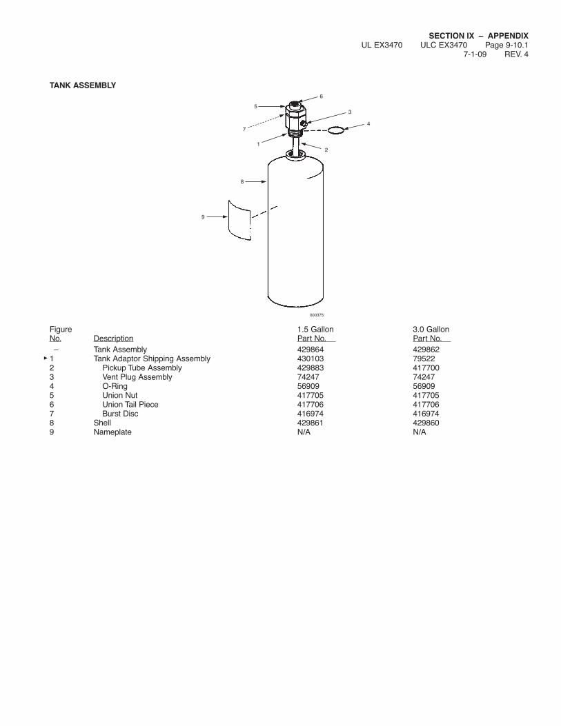
SECTION IX – APPENDIXUL EX3470 ULC EX3470 Page 9-10.1
7-1-09 REV. 4
TANK ASSEMBLY
Figure 1.5 Gallon 3.0 GallonNo. Description Part No. Part No.– Tank Assembly 429864 429862
1 Tank Adaptor Shipping Assembly 430103 795222 Pickup Tube Assembly 429883 4177003 Vent Plug Assembly 74247 742474 O-Ring 56909 569095 Union Nut 417705 4177056 Union Tail Piece 417706 4177067 Burst Disc 416974 4169748 Shell 429861 4298609 Nameplate N/A N/A
6
9
8
1
4
2
7
35
000375

SECTION IX – APPENDIXUL EX3470 ULC EX3470 Page 9-10.2REV. 2 4-1-06
REMOTE RELEASE
FigureNo. Description Part No.
— Remote Release 4334851 Mounting Box 4192952 Cover 4192963 Maintenance Label 173514 Spring 790945 Speed Nut 4234796 Machine Screw 149737 Hex Nut 147328 Lockwasher 73109 101 Release 433702
10 Spacer 7655511 Screw 7134212 Cover Screw 1536213 Tension Lever and Bracket Assembly 7930014 Gasket 18115 101 Cartridge (Order Separately) (Not Shown) (TC/DOT) 423439
(DOT) 15850
007499
10
9
1
2
3
4
11
13
6, 7, 8
14
5
12
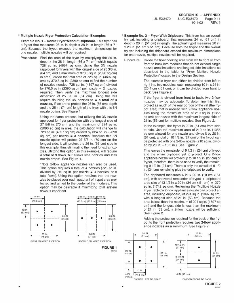
SECTION IX – APPENDIXUL EX3470 ULC EX3470 Page 9-11
10-1-02 REV. 5
Multiple Nozzle Fryer Protection Calculation Examples
Example No. 1 – Donut Fryer Without Dripboard. This fryer hasa frypot that measures 26 in. in depth x 28 in. in length (66 x 71cm). Because the frypot exceeds the maximum dimensions forone nozzle, multiple nozzles will be required.
Procedure: Find the area of the fryer by multiplying the 26 in.depth x the 28 in. length (66 x 71 cm) which equals728 sq in. (4697 sq cm). Using the 3N nozzle(approved for fryers with the longest side of 25 3/8 in.(64 cm) and a maximum of 370.5 sq in. (2390 sq cm)in area), divide the total area of 728 sq. in. (4697 sq.cm) by 370.5 sq in. (2390 sq cm) to find the numberof nozzles needed. 728 sq. in. (4697 sq cm) dividedby 370.5 sq in. (2390 sq cm) per nozzle = 2 nozzlesrequired. Then verify the maximum longest sidedimension of 25 3/8 in. (64 cm). Doing this willrequire doubling the 3N nozzles to = a total of 4nozzles, if we are to protect the 26 in. (66 cm) depthand the 28 in. (71 cm) length of the fryer with this 3Nnozzle option. See Figure 1.
Using the same process, but utilizing the 3N nozzleapproved for fryer protection with the longest side of27 5/8 in. (70 cm) and the maximum of 324 sq in.(2090 sq cm) in area, the calculation will change to728 sq in. (4697 sq cm) divided by 324 sq. in. (2090sq. cm) per nozzle = 3 nozzles. Because this 3Nnozzle option will protect 27 5/8 in. (70 cm) on thelongest side, it will protect the 26 in. (66 cm) side inthis example, thus eliminating the need for extra noz-zles. Utilizing this option, in this example, will requirea total of 9 flows, but allows less nozzles and lessnozzle drops*. See Figure 1.
*Note: 2-flow appliance nozzles can also be used.This option requires a total of 4 nozzles (728 sq in.divided by 210 sq in. per nozzle = 4 nozzles, or 8total flows). Using this option requires that the noz-zles be placed over each quadrant of frypot area pro-tected and aimed to the center of the modules. Thisoption may be desirable if minimizing total systemflows is important.
FIGURE 1002466
Example No. 2 – Fryer With Dripboard. This fryer has an overallfry vat, including a dripboard, that measures 24 in. (61 cm) indepth x 20 in. (51 cm) in length. The actual frypot measures 20 in.x 20 in. (51 cm x 51 cm). Because both the frypot and the overallfry vat including the dripboard exceed the maximum dimensionsfor one nozzle, multiple nozzles will be required.
Procedure: Divide the fryer cooking area from left to right or fromfront to back into modules that do not exceed singlenozzle area limitations and longest side limitations asdescribed in the table for “Fryer Multiple NozzleProtection” located in the Design Section.
The example fryer can either be divided from left toright into two modules, each measuring 10 in. x 24 in.(25.4 cm x 61 cm), or it can be divided from front toback. See Figure 2.
If the fryer is divided from front to back, two 2-flownozzles may be adequate. To determine this, firstprotect as much of the rear portion of the vat (the fry-pot area) that is allowed with 2-flow appliance noz-zles using the maximum area of 210 sq in. (1355sq cm) per nozzle with the maximum longest side of21 in. (53 cm) for multiple nozzles. See Figure 2.
In the example, the frypot is 20 in. (51 cm) from sideto side. Use the maximum area of 210 sq in. (1355sq cm) allowed for one nozzle and divide it by 20 in.(51 cm), a total of 10 1/2 in. (27 cm) of the frypot canbe protected with one 2-flow nozzle (210 sq in. divid-ed by 20 in. = 10.5 in.). See Figure 2.
This leaves the remainder of 9 1/2 in. (24 cm) of frypotand the entire dripboard yet to protect. One 2-flowappliance nozzle will protect up to 10 1/2 in. (27 cm) offrypot, therefore, there is no need to verify the remain-ing 9 1/2 in. (24 cm). There is only the overall of 9 1/2in. (24 cm) remaining plus the dripboard to verify.
The dripboard measures 4 in. x 20 in. (10 cm x 51cm), with an overall remainder of frypot + dripboardarea size of 13 1/2 in. x 20 in. (34 cm x 51 cm) = 270sq in. (1742 sq cm). Reviewing the “Multiple NozzleFryer Table,” a 2-flow appliance nozzle can protect anarea, including dripboard, of 294 sq in. (1897 sq cm)with a longest side of 21 in. (53 cm). Because thearea is less than the maximum of 294 sq in. (1897 sqcm) and the longest side is less than the maximumof 21 in. (53 cm), a 2-flow nozzle will be sufficient.See Figure 2.
Adding the protection required for the back of the fry-pot to the front protection requires two 2-flow appli-ance nozzles as a minimum. See Figure 2.
FIGURE 2002467
FIRST 3N NOZZLE OPTION SECOND 3N NOZZLE OPTION
28 IN.(71 cm)
26 IN.(66 cm)
13 IN.(33 cm)
26 IN.(66 cm)
14 IN.
(35.6 cm)
9 3/8 IN.
(23.8 cm)
9 3/8 IN.
(23.8 cm)
9 1/4 IN.
(23.5 cm)
28 IN.(71 cm)
DIVIDED LEFT TO RIGHT
4 IN.(10 cm)
DIVIDED FRONT TO BACK
20 IN.(51 cm)
20 IN.(51 cm)
24 IN.(61 cm)
20 IN.(51 cm) 24 IN.
(61 cm)
10 IN.
(25.4 cm) 4 IN. (10 cm)
10 1/2 IN.(27 cm)
9 1/2 IN.(24 cm)

SECTION IX – APPENDIXUL EX3470 ULC EX3470 Page 9-12REV. 4 7-1-09
WIRING DIAGRAM
NFPA standards require simultaneous operation for fire suppres-sion systems when two or more hazards can be simultaneouslyinvolved in fire by reason of their proximity. To accomplish simulta-neous operation, the 120 VAC Electric AUTOMAN RegulatedRelease Assembly can be used. This release can be activatedindependently by fusible line operation exactly like the mechanicalversion and can also be triggered electrically using a snap actionswitch from another 120 VAC Electric AUTOMAN RegulatedRelease Assembly or a Mechanical AUTOMAN RegulatedRelease Assembly. The electrical wiring used to connect from oneAUTOMAN Regulated Release Assembly to another will not besupervised. However, NFPA 96 allows an exception for electricallyoperated systems which “include automatic mechanical detection(fusible link) and actuation as a backup detection system.”
In the case of multiple hoods sharing a common exhaust duct,NFPA 17A requires one of two forms of simultaneous operation.The following wiring diagrams (See Figures 3 and 4) identify twoprinciple uses for the 120 VAC Electric AUTOMAN RegulatedRelease Assembly. Refer to Components Section, Page 3-1,Figure 3.
1. Simultaneous operation of all independent hood, duct, andappliance protection systems. See Figure 3.
2. Simultaneous operation of any hood, duct, and appliance pro-tection system and the system(s) protecting the entire commonexhaust duct. See Figure 4.
NEUTRAL
115 VAC60 HZHOT
ACTUATION LINE
ACTUATIONSOLENOID
DUAL ELECTRICSWITCH, PARTNO. 423879
ALL SYSTEMS MUST BE CONNECTED TO THE SAME POWER SOURCE
TYPICAL FOR ADDITIONALAUTOMANs – UP TO 4
AUTOMAN 1 AUTOMAN 2
Simultaneous Actuation of Multiple 120 VAC Electric ANSUL AUTOMANs
FIGURE 3008405

SECTION IX – APPENDIXUL EX3470 ULC EX3470 Page 9-13
7-1-09 REV. 0
WIRING DIAGRAM
Note 1: For fusible link detection only.
Note 2: Use ANSUL AUTOMANs with solenoid and electric switch. Replace Single Electric Switch, Part No. 423878, with Dual Switch Kit, Part No.423879.
Note 3: See Installation section of this manual for power capacity of solenoid and switches.
Note 4: This method does not provide supervision for battery or system wiring. The authority having jurisdiction (AHJ) may waive this requirement.
Note 5: When any one of the Mechanical ANSUL AUTOMANs is activated, the microswitch will transfer to the N.O. position, completing the circuit tothe N.C. switch in the Electrical ANSUL AUTOMAN. This will activate the ANSUL AUTOMAN. When the ANSUL AUTOMAN fires, the N.C.switch transfers to the N.O. position, opening the circuit to the solenoid.
120 VAC60 HZHOT
ACTUATION SOLENOID
NEUTRAL
MECHANICALAUTOMAN,TYP. 5
SWITCH,PART NO.423678
ALL SYSTEMS MUST BE CONNECTED TO THE SAME POWER SOURCE
ELECTRICAUTOMAN
ELECTRICAUTOMAN
#1 #2 #3 #4 #5
FIGURE 4008406
Simultaneous Actuation of One (1) or More 120 VAC Electric ANSUL AUTOMANs from Multiple Mechanical ANSUL AUTOMANs

SECTION IX – APPENDIXUL EX. 3470 ULC CEx747 Page 9-14REV. 0 7-1-09
NOTES: