manual ansul,inergen 200bar
DESCRIPTION
design installation and maintenance manual ANSUL INREGEN 200 bar.TRANSCRIPT

INERGEN® 200 BAR SYSTEMSDESIGN, INSTALLATION, RECHARGEAND MAINTENANCE MANUAL
ANSUL®
®
004439
7-15-02 1-4 1
7-15-02 1-8 1
7-15-02 1-24 1
7-15-02 200 Bar System 1Specification Data Sheet
7-15-02 Extinguishing Agent 1Data Sheet
7-15-02 MSDS 2
7-15-02 3-2 1
7-15-02 3-3 1
7-15-02 4-2 1
7-15-02 5-2 1
7-15-02 5-7 1
7-15-02 5-9 1
7-15-02 5-11 1
7-15-02 5-21 1
7-15-02 5-27 1
7-15-02 6-7 1
7-15-02 6-13 1
7-15-02 7-3 1
7-15-02 8-2 1
7-15-02 11-1 1
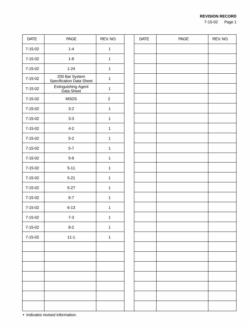
REVISION RECORD7-15-02 Page 1
DATE PAGE REV. NO. DATE PAGE REV. NO.
Indicates revised information.

ANSUL
INERGEN® 200 BAR SYSTEM
DESIGN, INSTALLATION, RECHARGE AND MAINTENANCE MANUAL
ANSUL PART NO. 430149-1
UNDERWRITERS LABORATORIES FILE NO. EX-4510
JULY 15, 2002

Form No. Pages
I. COMPONENTS 1-1 – 1-33
CV-98 CYLINDER SHIPPING ASSEMBLY F-2001249 1-1
AUTOPULSE® CONTROL SYSTEM F-2001250 1-2
ANSUL AUTOMAN® II-C RELEASING DEVICE F-2001251 1-3
SELECTOR VALVES F-2001252-1 1-4
PRESSURE OPERATED STACKABLE ACTUATOR F-2001253 1-5
BOOSTER ACTUATOR F-2001254 1-6
HF ELECTRIC ACTUATOR F-2001255 1-7
LEVER RELEASE ACTUATOR F-2001256-1 1-8
MANUAL PULL BOX F-2001257 1-9
CABLE WITH SWAGED END FITTING F-2001258 1-10
CORNER PULLEY F-2001259 1-11
DUAL/TRIPLE CONTROL BOXES F-2001260 1-12
REMOTE CABLE PULL EQUALIZER F-2001261 1-13
PRESSURE BLEEDER PLUG – 1/4 IN. F-2001262 1-14
FLEXIBLE DISCHARGE BEND F-2001263 1-15
CHECK VALVES F-2001264 1-16
HEADER VENT PLUG F-2001265 1-17
STAINLESS STEEL ACTUATION HOSE F-2001266 1-18
PRESSURE REDUCER/UNION F-2001267 1-19
FLANGED PRESSURE REDUCER F-2001269 1-20
DISCHARGE NOZZLE – 360° F-2001272 1-21
180° DISCHARGE NOZZLE F-2001273 1-22
NOZZLE DEFLECTOR SHIELD F-2001274 1-23
CYLINDER BRACKETING F-2001275-1 1-24
PRESSURE SWITCH – DPST F-2001276 1-25
PRESSURE SWITCH – DPDT-EXPLOSION-PROOF F-2001277 1-26
PRESSURE SWITCH – 3PST F-2001278 1-27
PRESSURE TRIP F-2001279 1-28
PRESSURE TEST ASSEMBLY F-2001280 1-29
NAMEPLATE – MAIN F-2001283 1-30
NAMEPLATE – RESERVE F-2001284 1-31
WARNING PLATE – INSIDE ROOM WITH ALARM F-2001285 1-32
WARNING PLATE – OUTSIDE ROOM WITHOUT ALARM F-2001286 1-33
II. SPECIFICATIONS
SYSTEM SPECIFICATION SHEET F-2001292-1
AGENT SPECIFICATION SHEET F-200045-1
MSDS F-9759-2
Table of Contents7-15-02 REV. 1
Page 1
ANSUL®
®

Form No. Pages
III. GENERAL INFORMATION 3-1 – 3-4
“INERGEN” AGENT 3-1
PERSONAL SAFETY 3-1
TYPE OF SYSTEM 3-1
TYPES OF ACTUATION 3-1Electrical 3-1Mechanical 3-1Pneumatic 3-2
INERGEN FLOW 3-2
TYPE OF DETECTION 3-2Electronic Control Panel 3-2Electronic Releasing Device 3-2
SYSTEM LIMITATIONS 3-2 – 3-4Design Limitations 3-2 – 3-3Flow Calculation Limitations 3-3 – 3-4
IV. PLANNING 4-1 – 4-2
INITIAL GENERAL INFORMATION 4-1
HAZARD INFORMATION 4-1INERGEN Supply Requirements 4-2Actuation and Alarm Requirements 4-2Piping and Wiring Information 4-2Ventilation and Leakage Concerns 4-2
V. DESIGN 5-1 – 5-27
APPLICATION METHOD 5-1 – 5-11
Total Flooding 5-1 – 5-11
SELECTOR VALVE SYSTEMS 5-11 – 5-13
SAMPLE APPLICATIONS 5-14
ACTUATION REQUIREMENTS 5-14Manual 5-14Pneumatic 5-14Electric 5-14Multiple Manifold Actuator 5-14Secondary Pilot Cylinder 5-14
ACCESSORIES 5-15 – 5-16
Mechanical Manual Pull Stations 5-15
Pressure Switch 5-15
Pressure Trip 5-15
Alarms 5-16
Control Panels 5-16
Table of Contents12-1-01
Page 2

Table of Contents12-1-01
Page 3
Form No. Pages
V. DESIGN (Continued)
RESERVE SYSTEM 5-16
DEVELOP BILL OF MATERIALS 5-16
“INERGEN” DESIGN CALCULATIONS WORKSHEET F-2001293 5-17
FLOODING FACTOR CHART 5-18 – 5-19
ATMOSPHERIC CORRECTION FACTORS CHART 5-20
DISCHARGE TIME CHART (FOR CLASS A FIRES) 5-21
PIPE SIZE ESTIMATION CHART 5-22
MAXIMUM PIPE PRESSURE CHART 5-23 – 5-25
EQUIVALENT LENGTH CHART 5-26
NOZZLE/PRESSURE REDUCER RANGE CHART 5-27
VI. INSTALLATION 6-1 – 6-17
MOUNTING COMPONENTS 6-1 – 6-4
Cylinder/Bracket Assembly 6-1 – 6-3
Releasing Devices 6-4
INSTALLING ACTUATION PIPING 6-4 – 6-5
General Piping Requirements 6-4
Actuation Piping Installation 6-5
INSTALLING DISTRIBUTION PIPING 6-6 – 6-11
Hanger Applications 6-6
General Piping Requirements 6-6 – 6-8
Distribution Manifold and Piping Installation 6-9 – 6-11
MAIN/RESERVE SYSTEM 6-11
INSTALLING DETECTION/ACTUATION SYSTEM 6-12
AUTOPULSE Control System with Electric Actuator 6-12
AUTOPULSE Control System with ANSUL AUTOMAN II-C Release 6-12
with Pneumatic Actuation
INSTALLING ACTUATOR 6-13 – 6-14
Pneumatic 6-13
Manual 6-13
Electric 6-14
Booster Actuator 6-14
HF Actuator 6-14
INSTALLING ACCESSORIES 6-14 – 6-17Manual Pull Station 6-14 – 6-16Alarms 6-16Pressure Trip 6-16 – 6-17Pressure Switch 6-17
Form No. Pages
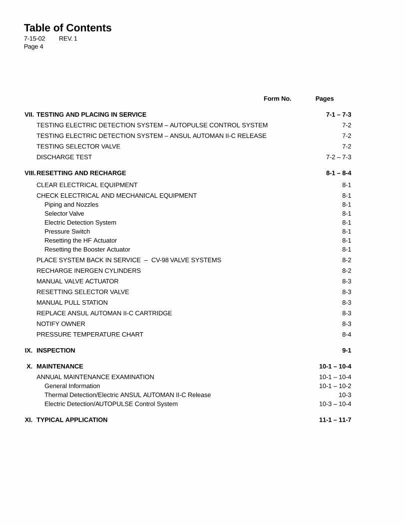
VII. TESTING AND PLACING IN SERVICE 7-1 – 7-3
TESTING ELECTRIC DETECTION SYSTEM – AUTOPULSE CONTROL SYSTEM 7-2
TESTING ELECTRIC DETECTION SYSTEM – ANSUL AUTOMAN II-C RELEASE 7-2
TESTING SELECTOR VALVE 7-2
DISCHARGE TEST 7-2 – 7-3
VIII.RESETTING AND RECHARGE 8-1 – 8-4
CLEAR ELECTRICAL EQUIPMENT 8-1
CHECK ELECTRICAL AND MECHANICAL EQUIPMENT 8-1Piping and Nozzles 8-1Selector Valve 8-1Electric Detection System 8-1Pressure Switch 8-1Resetting the HF Actuator 8-1Resetting the Booster Actuator 8-1
PLACE SYSTEM BACK IN SERVICE – CV-98 VALVE SYSTEMS 8-2
RECHARGE INERGEN CYLINDERS 8-2
MANUAL VALVE ACTUATOR 8-3
RESETTING SELECTOR VALVE 8-3
MANUAL PULL STATION 8-3
REPLACE ANSUL AUTOMAN II-C CARTRIDGE 8-3
NOTIFY OWNER 8-3
PRESSURE TEMPERATURE CHART 8-4
IX. INSPECTION 9-1
X. MAINTENANCE 10-1 – 10-4
ANNUAL MAINTENANCE EXAMINATION 10-1 – 10-4General Information 10-1 – 10-2Thermal Detection/Electric ANSUL AUTOMAN II-C Release 10-3 Electric Detection/AUTOPULSE Control System 10-3 – 10-4
XI. TYPICAL APPLICATION 11-1 – 11-7
Table of Contents7-15-02 REV. 1Page 4

CV-98 INERGEN Valve
The CV-98 valve has a ten (10) year warranty. The valverequires no internal maintenance. The valve is sealedclosed and must not be disassembled. If there is ever amalfunction of the CV-98 valve, the complete valve must besent back to Ansul for warranty replacement. If the exter-nal seal is broken, the warranty is voided.NOTE: Use Flexible Discharge Bend, Part No. 427082, when attaching
valve to supply pipe or manifold.
ANSUL and INERGEN are trademarks of Ansul Incorporated or its affiliates.
System ComponentsUL EX-4510 12-1-01 Page 1-1
Description
The cylinder is factory filled with INERGEN® agent. A singlecylinder may be used or multiple cylinders can be manifoldedtogether to obtain the required quantity of agent for total flood-ing. The cylinder valve can be actuated electrically, pneumati-cally, and/or manually with approved valve actuation compo-nents. All valves are equipped with an anti-recoil feature.
The cylinders are shipped with a maintenance record cardand protective shipping cap attached to the threaded neckof each cylinder. This cap entirely encloses and protectsthe valve while in shipment.
The equivalent length of the valve is equal to 20 ft. (6.1 m)of 1/2 in. Sch. 40 pipe.
CV-98 Valve / Cylinder Shipping Assembly
Component Material Approvals
Cylinder Steel Meets DOT3AA3000
Valve Brass
Safety Relief Valve Brass
Valve/Cylinder UL ListedAssembly (EX-4510)
Shipping Cap Steel
Shipping Nominal Cylinder Actual INERGEN Approximate Dimension DimensionAssembly Size Agent Quantity Weight A BPart No. ft.3 (m3) ft.3 m3 lb. (kg) in. (cm) in. (cm)
430952 575 (16.3) 572 (16.2) 322 (146) 68.5 (174.0) 11.0 (27.9)
PRESSUREGAUGE
SAFETYRELIEFVALVE
002252
ANSUL INCORPORATED, ONE STANTON STREET, MARINETTE, WI 54143-2542 715-735-7411 Form No. F-2001249 ©2001 Ansul Incorporated Litho in U.S.A.
VALVE
HEIGHT TO OUTLETCENTER
002251
RECORDTAG
PRESSUREGAUGE
CYLINDERSHIPPING CAP
VALVE SHIPPING CAP
B
A
ANSUL®
®�

System ComponentsUL EX-4510 12-1-01 Page 1-2
Description
The AUTOPULSE® Control System provides a range offeatures and benefits, ranging from simple detectionthrough counting circuits.
Several models of the AUTOPULSE® Control System areavailable depending on the type of hazard being protected.
Refer to the Ansul Detection and Control ApplicationManual for detailed information concerning allAUTOPULSE Control Systems.
AUTOPULSE® Control System
ANSUL, AUTOPULSE and INERGEN are trademarks of Ansul Incorporated or its affiliates.
002195
ANSUL INCORPORATED, ONE STANTON STREET, MARINETTE, WI 54143-2542 715-735-7411 Form No. F-2001250 ©2001 Ansul Incorporated Litho in U.S.A.
ANSUL®
®�

System ComponentsUL EX-4510 12-1-01 Page 1-3
Description
The ANSUL AUTOMAN II-C Releasing Device consists of ametal enclosure which contains a spring-loaded puncturepin release mechanism, an actuation cartridge, electricalcircuitry, and an input/output terminal strip for making elec-trical connections. The ANSUL AUTOMAN II-C releasingdevice provides automatic pneumatic actuation of theINERGEN System. When wired to an AUTOPULSE ControlSystem, it will provide supervised electric detection andrelease. It also provides manual actuation using the strikebutton on the release enclosure and with the optionalremote manual cable pull station. When an AUTOPULSEControl System is used, manual actuation is accomplishedusing an electric manual pull station.
ANSUL AUTOMAN II-C Releasing Device
RELEASEMECHANISM
STRIKEBUTTON
TERMINALBOARD
NAMEPLATE
000442
Component Approvals
ANSUL AUTOMAN II-C Releasing UL ListedDevice (R5998)
ANSUL AUTOMAN II-C ReleasingDevice (Explosion-Proof)
Shipping AssemblyPart No. Description
17728 ANSUL AUTOMAN II-C Releasing Device, 24 VDC31492 ANSUL AUTOMAN II-C Releasing Device, Explosion-Proof, 24 VDC32525 ANSUL AUTOMAN II-C Releasing Device, Explosion-Proof, 120 VAC32526 ANSUL AUTOMAN II-C Releasing Device, Explosion-Proof, 240 VAC5373 LT-30-R Nitrogen Cartridge
ANSUL, INERGEN, ANSUL AUTOMAN, and AUTOPULSE are trademarks of Ansul Incorporated or its affiliates.
ANSUL INCORPORATED, ONE STANTON STREET, MARINETTE, WI 54143-2542 715-735-7411 Form No. F-2001251 ©2001 Ansul Incorporated Litho in U.S.A.
ANSUL®
®�
System ComponentsUL EX-4510 7-15-02 Page 1-4
REV. 1
Description
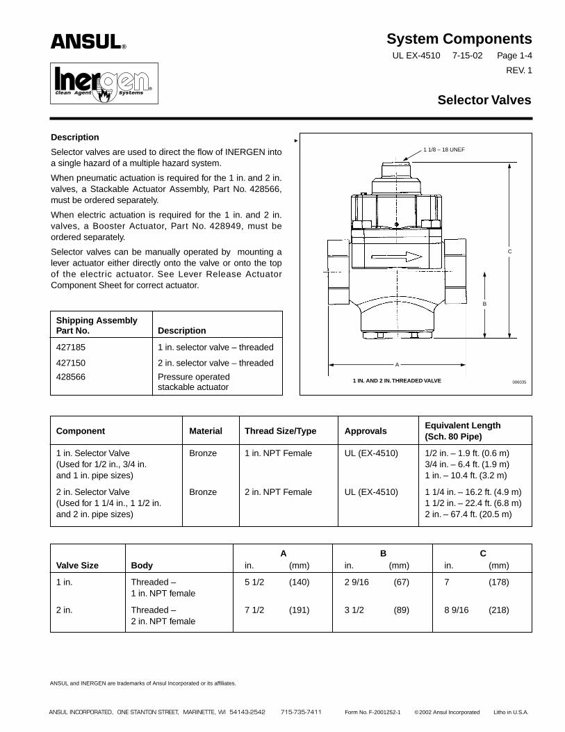
Selector valves are used to direct the flow of INERGEN intoa single hazard of a multiple hazard system.
When pneumatic actuation is required for the 1 in. and 2 in.valves, a Stackable Actuator Assembly, Part No. 428566,must be ordered separately.
When electric actuation is required for the 1 in. and 2 in.valves, a Booster Actuator, Part No. 428949, must beordered separately.
Selector valves can be manually operated by mounting alever actuator either directly onto the valve or onto the topof the electric actuator. See Lever Release ActuatorComponent Sheet for correct actuator.
Selector Valves
Component Material Thread Size/Type ApprovalsEquivalent Length(Sch. 80 Pipe)
1 in. Selector Valve Bronze 1 in. NPT Female UL (EX-4510) 1/2 in. – 1.9 ft. (0.6 m)(Used for 1/2 in., 3/4 in. 3/4 in. – 6.4 ft. (1.9 m)and 1 in. pipe sizes) 1 in. – 10.4 ft. (3.2 m)
2 in. Selector Valve Bronze 2 in. NPT Female UL (EX-4510) 1 1/4 in. – 16.2 ft. (4.9 m)(Used for 1 1/4 in., 1 1/2 in. 1 1/2 in. – 22.4 ft. (6.8 m)and 2 in. pipe sizes) 2 in. – 67.4 ft. (20.5 m)
Shipping AssemblyPart No. Description
427185 1 in. selector valve – threaded
427150 2 in. selector valve – threaded
428566 Pressure operatedstackable actuator
ANSUL®
®
ANSUL INCORPORATED, ONE STANTON STREET, MARINETTE, WI 54143-2542 715-735-7411 Form No. F-2001252-1 ©2002 Ansul Incorporated Litho in U.S.A.
ANSUL and INERGEN are trademarks of Ansul Incorporated or its affiliates.
A B CValve Size Body in. (mm) in. (mm) in. (mm)
1 in. Threaded – 5 1/2 (140) 2 9/16 (67) 7 (178)1 in. NPT female
2 in. Threaded – 7 1/2 (191) 3 1/2 (89) 8 9/16 (218)2 in. NPT female
0060351 IN. AND 2 IN.THREADED VALVE
A
B
C
1 1/8 – 18 UNEF
System ComponentsUL EX-4510 12-1-01 Page 1-5
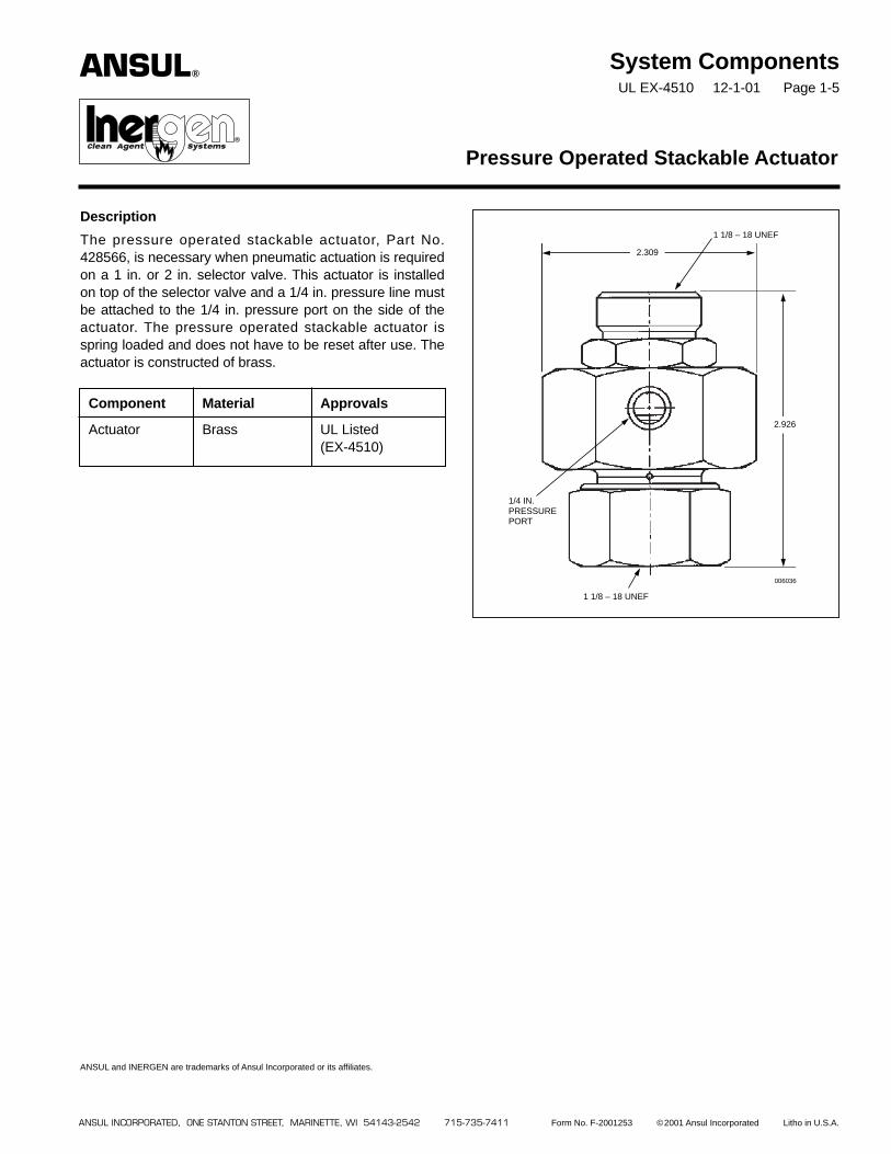
Description
The pressure operated stackable actuator, Part No.428566, is necessary when pneumatic actuation is requiredon a 1 in. or 2 in. selector valve. This actuator is installedon top of the selector valve and a 1/4 in. pressure line mustbe attached to the 1/4 in. pressure port on the side of theactuator. The pressure operated stackable actuator isspring loaded and does not have to be reset after use. Theactuator is constructed of brass.
Pressure Operated Stackable Actuator
ANSUL INCORPORATED, ONE STANTON STREET, MARINETTE, WI 54143-2542 715-735-7411 Form No. F-2001253 ©2001 Ansul Incorporated Litho in U.S.A.
ANSUL and INERGEN are trademarks of Ansul Incorporated or its affiliates.
006036
2.309
2.926
1/4 IN.PRESSUREPORT
1 1/8 – 18 UNEF
1 1/8 – 18 UNEF
ANSUL®
®�
Component Material Approvals
Actuator Brass UL Listed(EX-4510)
Description
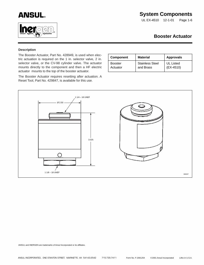
The Booster Actuator, Part No. 428949, is used when elec-tric actuation is required on the 1 in. selector valve, 2 in.selector valve, or the CV-98 cylinder valve. The actuatormounts directly to the component and then a HF electricactuator mounts to the top of the booster actuator.
The Booster Actuator requires resetting after actuation. AReset Tool, Part No. 429847, is available for this use.
System ComponentsUL EX-4510 12-1-01 Page 1-6
Booster Actuator
ANSUL INCORPORATED, ONE STANTON STREET, MARINETTE, WI 54143-2542 715-735-7411 Form No. F-2001254 ©2001 Ansul Incorporated Litho in U.S.A.
ANSUL and INERGEN are trademarks of Ansul Incorporated or its affiliates.
006037
Ø 2.50
3.025
1 1/4 – 18 UNEF
1 1/8 – 18 UNEF
Component Material Approvals
Booster Stainless Steel UL ListedActuator and Brass (EX-4510)
ANSUL®
®�
4 1/2 IN.(114 mm)
2 1/4 IN.(57 mm)
System ComponentsUL EX-4510 12-1-01 Page 1-7
Description
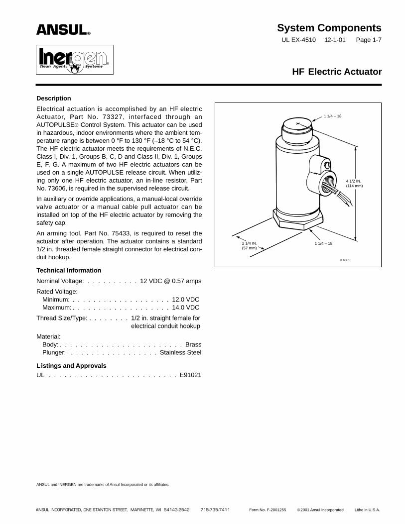
Electrical actuation is accomplished by an HF electricActuator, Part No. 73327, interfaced through anAUTOPULSE® Control System. This actuator can be usedin hazardous, indoor environments where the ambient tem-perature range is between 0 °F to 130 °F (–18 °C to 54 °C).The HF electric actuator meets the requirements of N.E.C.Class I, Div. 1, Groups B, C, D and Class II, Div. 1, GroupsE, F, G. A maximum of two HF electric actuators can beused on a single AUTOPULSE release circuit. When utiliz-ing only one HF electric actuator, an in-line resistor, PartNo. 73606, is required in the supervised release circuit.
In auxiliary or override applications, a manual-local overridevalve actuator or a manual cable pull actuator can beinstalled on top of the HF electric actuator by removing thesafety cap.
An arming tool, Part No. 75433, is required to reset theactuator after operation. The actuator contains a standard1/2 in. threaded female straight connector for electrical con-duit hookup.
Technical Information
Nominal Voltage: . . . . . . . . . . 12 VDC @ 0.57 amps
Rated Voltage:Minimum: . . . . . . . . . . . . . . . . . . . 12.0 VDCMaximum: . . . . . . . . . . . . . . . . . . . 14.0 VDC
Thread Size/Type: . . . . . . . . 1/2 in. straight female forelectrical conduit hookup
Material:Body: . . . . . . . . . . . . . . . . . . . . . . . . BrassPlunger: . . . . . . . . . . . . . . . . . Stainless Steel
Listings and ApprovalsUL . . . . . . . . . . . . . . . . . . . . . . . . . E91021
HF Electric Actuator
ANSUL INCORPORATED, ONE STANTON STREET, MARINETTE, WI 54143-2542 715-735-7411 Form No. F-2001255 ©2001 Ansul Incorporated Litho in U.S.A.
ANSUL and INERGEN are trademarks of Ansul Incorporated or its affiliates.
006361
1 1/4 – 18
ANSUL®
®�
1 1/4 – 18

System ComponentsUL EX-4510 7-15-02 Page 1-8
REV. 1
Description
The manual lever release actuator provides a manualmeans of actuating cylinder valves and selector valves. Thiscan be accomplished by direct manual actuation of its pulllever or cable actuation when used in conjunction with aremote manual pull station. When used with a remote man-ual pull station, the pull station must contain the compo-nents necessary to meet the actuator lever travelingrequirements of 7 in. (178 mm).
The actuator is shipped with ring pin and chain attached. Ifthe ring pin is not required, it must be removed. Failure toremove the ring pin/chain assembly will prevent systemactuation if a remote cable pull actuation system isemployed and the ring pin is accidentally installed in theactuator.
Four actuators are available. Each is designed for a specificcomponent.
Lever Release Actuator
Component Material Approvals
All Manual Brass with UL ListedCable-pull Stainless Steel Pin (EX-4510)Actuators
3 7/8 IN.(9.8 cm)
DEPTH: 3 7/8 IN. (7.6 cm)
3 7/8 IN.*(9.8 cm)
000897
* Add 1 9/16 in. (3.9 cm) to height when lever is in the straight up position.
ANSUL INCORPORATED, ONE STANTON STREET, MARINETTE, WI 54143-2542 715-735-7411 Form No. F-2001256-1 ©2002 Ansul Incorporated Litho in U.S.A.
ANSUL and INERGEN are trademarks of Ansul Incorporated or its affiliates.
PIN
ShippingAssemblyPart No. Description
423309 Lever Release (1 1/8-18 mountingthread) – Mounts directly to aCV-98 cylinder valve.
70846 Lever Release (1 1/4-18 mountingthread) – Mounts directly to anHF electric actuator.
427207 Lever Release (1 1/8-18 mountingthread) – Mounts directly to the 1 in.and 2 in. selector valves. Mounts direct-ly to pressure operated stackable actu-ator for 1 in. and 2 in. selector valves.Actuator has the handle painted red.
ANSUL®
®
Description
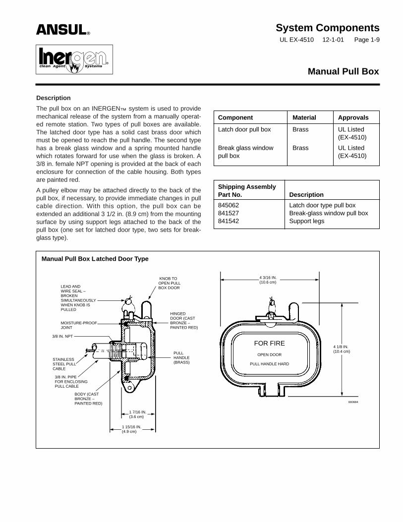
The pull box on an INERGEN™ system is used to providemechanical release of the system from a manually operat-ed remote station. Two types of pull boxes are available.The latched door type has a solid cast brass door whichmust be opened to reach the pull handle. The second typehas a break glass window and a spring mounted handlewhich rotates forward for use when the glass is broken. A3/8 in. female NPT opening is provided at the back of eachenclosure for connection of the cable housing. Both typesare painted red.
A pulley elbow may be attached directly to the back of thepull box, if necessary, to provide immediate changes in pullcable direction. With this option, the pull box can beextended an additional 3 1/2 in. (8.9 cm) from the mountingsurface by using support legs attached to the back of thepull box (one set for latched door type, two sets for break-glass type).
System ComponentsUL EX-4510 12-1-01 Page 1-9
Manual Pull Box
Component Material Approvals
Latch door pull box Brass UL Listed(EX-4510)
Break glass window Brass UL Listedpull box (EX-4510)
Shipping AssemblyPart No. Description
845062 Latch door type pull box841527 Break-glass window pull box841542 Support legs
Manual Pull Box Latched Door Type
KNOB TOOPEN PULLBOX DOORLEAD AND
WIRE SEAL –BROKENSIMULTANEOUSLYWHEN KNOB ISPULLED
HINGEDDOOR (CASTBRONZE –PAINTED RED)
MOISTURE-PROOFJOINT
3/8 IN. NPT
PULLHANDLE(BRASS)
FOR FIRE
OPEN DOOR
PULL HANDLE HARDSTAINLESSSTEEL PULLCABLE
3/8 IN. PIPEFOR ENCLOSINGPULL CABLE
BODY (CASTBRONZE –PAINTED RED)
1 7/16 IN.(3.6 cm)
1 15/16 IN.(4.9 cm)
4 3/16 IN.(10.6 cm)
4 1/8 IN.(10.4 cm)
ANSUL®
®�
000684

ANSUL and INERGEN are trademarks of Ansul Incorporated or its affiliates.
Manual Pull Box Break Glass Type “A”
SPRING FORCESHANDLEOUT INTOOPERATINGPOSITIONWHEN GLASSIS BROKEN
MOISTUREPROOFJOINT
PULLHANDLE
GLASSFRONT
3/8 IN. PIPETO ENCLOSEPULL CABLE
1/16 IN. STAINLESSSTEEL PULL CABLE
CASTBRASSHINGEDCOVER(PAINTEDRED)
CAST BRASSBODY(PAINTED RED)
STOWAGE SPACEFOR SPAREDISCS ANDWASHERS
2 13/16 IN.(7.1 cm)
ANSUL INCORPORATED, ONE STANTON STREET, MARINETTE, WI 54143-2542 715-735-7411 Form No. F-2001257 ©2001 Ansul Incorporated Litho in U.S.A.
PROTECTED HAZARDENGRAVED INNAMEPLATE (SPECIFY)
4 7/16 IN.(11.2 cm)
3 1/4 IN.(8.2 cm)
4 – 3/16 IN.MOUNTINGHOLES
4 7/8 IN.(12.3 cm)
3 IN.(7.6 cm)
IN CASE OF FIREBREAK GLASS AND
PULL HANDLE HARDUNTIL RED PAINTMARK ON CABLE
SHOWS
BRASS HAMMERAND CHAINSECUREDTO BOX
ANSUL INCORPORATED, ONE STANTON STREET, MARINETTE, WI 54143-2542 715-735-7411 Form No. F-2001258 ©2001 Ansul Incorporated Litho in U.S.A.
System ComponentsUL EX-4510 12-1-01 Page 1-10
Description
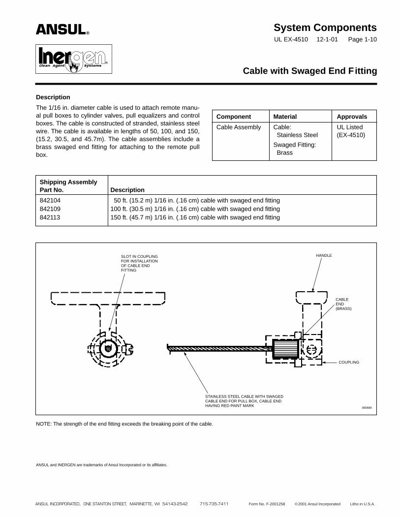
The 1/16 in. diameter cable is used to attach remote manu-al pull boxes to cylinder valves, pull equalizers and controlboxes. The cable is constructed of stranded, stainless steelwire. The cable is available in lengths of 50, 100, and 150,(15.2, 30.5, and 45.7m). The cable assemblies include abrass swaged end fitting for attaching to the remote pullbox.
Cable with Swaged End Fitting
Component Material Approvals
Cable Assembly Cable: UL ListedStainless Steel (EX-4510)
Swaged Fitting:Brass
Shipping AssemblyPart No. Description
842104 50 ft. (15.2 m) 1/16 in. (.16 cm) cable with swaged end fitting842109 100 ft. (30.5 m) 1/16 in. (.16 cm) cable with swaged end fitting842113 150 ft. (45.7 m) 1/16 in. (.16 cm) cable with swaged end fitting
NOTE: The strength of the end fitting exceeds the breaking point of the cable.
ANSUL and INERGEN are trademarks of Ansul Incorporated or its affiliates.
HANDLE
CABLEEND(BRASS)
COUPLING
SLOT IN COUPLINGFOR INSTALLATIONOF CABLE ENDFITTING
STAINLESS STEEL CABLE WITH SWAGEDCABLE END FOR PULL BOX, CABLE ENDHAVING RED PAINT MARK 000689
ANSUL®
®�
System ComponentsUL EX-4510 12-1-01 Page 1-11
Description
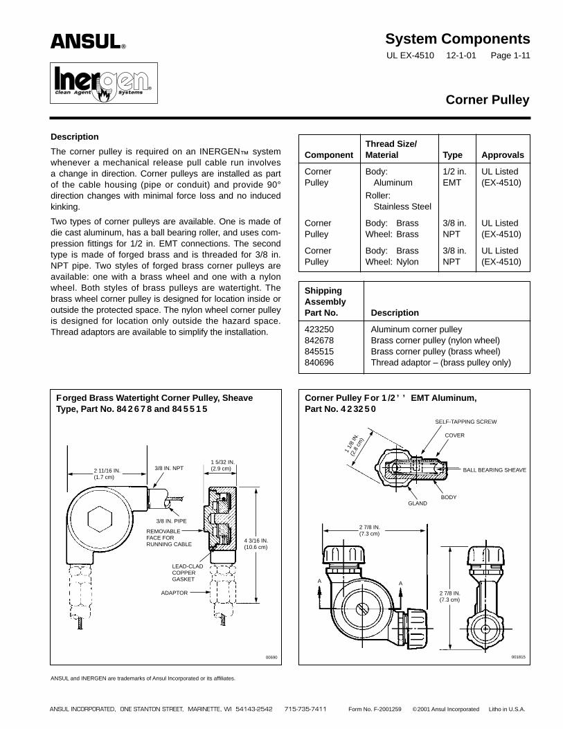
The corner pulley is required on an INERGEN™ systemwhenever a mechanical release pull cable run involvesa change in direction. Corner pulleys are installed as partof the cable housing (pipe or conduit) and provide 90°direction changes with minimal force loss and no inducedkinking.
Two types of corner pulleys are available. One is made ofdie cast aluminum, has a ball bearing roller, and uses com-pression fittings for 1/2 in. EMT connections. The secondtype is made of forged brass and is threaded for 3/8 in.NPT pipe. Two styles of forged brass corner pulleys areavailable: one with a brass wheel and one with a nylonwheel. Both styles of brass pulleys are watertight. Thebrass wheel corner pulley is designed for location inside oroutside the protected space. The nylon wheel corner pulleyis designed for location only outside the hazard space.Thread adaptors are available to simplify the installation.
ANSUL and INERGEN are trademarks of Ansul Incorporated or its affiliates.
Corner Pulley
Thread Size/Component Material Type Approvals
Corner Body: 1/2 in. UL ListedPulley Aluminum EMT (EX-4510)
Roller:Stainless Steel
Corner Body: Brass 3/8 in. UL ListedPulley Wheel: Brass NPT (EX-4510)
Corner Body: Brass 3/8 in. UL ListedPulley Wheel: Nylon NPT (EX-4510)
ShippingAssemblyPart No. Description
423250 Aluminum corner pulley842678 Brass corner pulley (nylon wheel)845515 Brass corner pulley (brass wheel)840696 Thread adaptor – (brass pulley only)
ANSUL®
®�
ANSUL INCORPORATED, ONE STANTON STREET, MARINETTE, WI 54143-2542 715-735-7411 Form No. F-2001259 ©2001 Ansul Incorporated Litho in U.S.A.
Forged Brass Watertight Corner Pulley, SheaveType, Part No. 842678 and 845515
Corner Pulley For 1/2’’ EMT Aluminum,Part No. 423250
4 3/16 IN.(10.6 cm)
2 11/16 IN.(1.7 cm)
3/8 IN. NPT1 5/32 IN.(2.9 cm)
LEAD-CLADCOPPERGASKET
3/8 IN. PIPE
REMOVABLEFACE FORRUNNING CABLE
ADAPTOR
00690
1 1/
8 IN
.(2
.8 c
m)
GLANDBODY
COVER
SELF-TAPPING SCREW
BALL BEARING SHEAVE
2 7/8 IN.(7.3 cm)
2 7/8 IN.(7.3 cm)
001815
A A
System ComponentsUL EX-4510 12-1-01 Page 1-12
Description
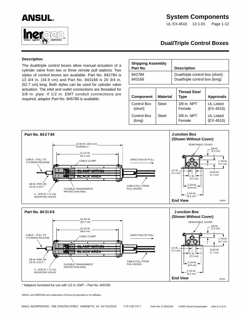
The dual/triple control boxes allow manual actuation of acylinder valve from two or three remote pull stations. Twostyles of control boxes are available. Part No. 842784 is13 3/4 in. (34.9 cm) and Part No. 843166 is 20 3/4 in.(52.7 cm) long. Both styles can be used for cylinder valveactuation. The inlet and outlet connections are threaded for3/8 in. pipe. If 1/2 in. EMT conduit connections arerequired, adaptor Part No. 845780 is available.
Dual/Triple Control Boxes
Shipping AssemblyPart No. Description
842784 Dual/triple control box (short)843166 Dual/triple control box (long)
Thread Size/Component Material Type Approvals
Control Box Steel 3/8 in. NPT UL Listed(short) Female (EX-4510)
Control Box Steel 3/8 in. NPT UL Listed(long) Female (EX-4510)
Part No. 842784 Junction Box(Shown Without Cover)
End View
5/8 IN.(1.5 cm)
3 1/4 IN.(8.2 cm)
1/2 IN.(1.2 cm)
2 3/4 IN.(6.9 cm)
1 7/8 IN.(4.7 cm)
11/16 IN.(1.7 cm)
REMOVABLE COVER
1 IN.(2.5 cm)
12 1/4 IN.(31.1 cm)
13 3/4 IN. (34.9 cm)(OVERALL)
DIRECTION OF PULL
CABLE-PULL FROMPULL-BOXESFLEXIBLE TRANSPARENT
PROTECTION RING
CABLE CLAMPCABLE – PULL TOCYLINDER RELEASE
3/8 IN. PIPE OR1/2 IN. E.M.T.*
4 – 9/32 IN. (.71 cm)MOUNTING HOLES
CLAMP WITHINBLACK AREA
ANSUL®
®�
ANSUL INCORPORATED, ONE STANTON STREET, MARINETTE, WI 54143-2542 715-735-7411 Form No. F-2001260 ©2001 Ansul Incorporated Litho in U.S.A.
Part No. 843166 Junction Box(Shown Without Cover)
End View
5/8 IN.(1.5 cm)
3 1/4 IN.(8.2 cm)
1/2 IN.(1.2 cm)
2 3/4 IN.(6.9 cm)
1 7/8 IN.(4.7 cm)
11/16 IN.(1.7 cm)
REMOVABLE COVER
1 IN.(2.5 cm)
19 1/4 IN.(48.8 cm)
20 3/4 IN.(52.7 cm)
DIRECTION OF PULL
CABLE-PULL FROMPULL-BOXESFLEXIBLE TRANSPARENT
PROTECTION RING
CABLE CLAMPCABLE – PULL TOCYLINDER RELEASE
3/8 IN. PIPE OR1/2 IN. E.M.T.*
4 – 9/32 IN. (.71 cm)MOUNTING HOLES
CLAMP WITHINBLACK AREA
* Adaptors furnished for use with 1/2 in. EMT – Part No. 845780
ANSUL and INERGEN are trademarks of Ansul Incorporated or its affiliates.
000685
000685

ANSUL INCORPORATED, ONE STANTON STREET, MARINETTE, WI 54143-2542 715-735-7411 Form No. F-2001261 ©2001 Ansul Incorporated Litho in
System ComponentsUL EX-4510 12-1-01 Page 1-13
Description
The remote cable pull equalizer is used in systems wheremanual actuation of the cylinder valve and operation of aselector valve must be accomplished at the same time. Thepull equalizer is mounted in the remote pull station cableline. By pulling the remote pull box, the cable attached tothe pull equalizer will pull the internal cable clamp in thepull equalizer which in turn will pull the cables attached tothe cylinder valve and selector valve, causing them to oper-ate. Two styles of pull equalizers are available. Part No.842791 is 13 3/4 in. (34.9 cm) long and Part No. 843168 is20 3/4 in. (52.7 cm). Only the longest equalizer, Part No.843168, can be used for valves utilizing sectors. The inletand outlet connections are threaded for 3/8 in. pipe. If1/2 in. EMT conduit connections are required, adaptor PartNo. 845780 is available.
Remote Cable Pull Equalizer
Shipping AssemblyPart No. Description
842791 Remote cable pull equalizer(short)
843168 Remote cable pull equalizer(long)
Part No. 842791 Equalizer Box(Shown Without Cover)
End View
3 1/4 IN.(8.2 cm)
2 3/4 IN.(6.9 cm)
1 7/8 IN.(4.7 cm)
11/16 IN.(1.7 cm)
REMOVABLE COVER
1 IN.(2.5 cm)
12 1/4 IN.(31.1 cm)
13 3/4 IN. (34.9 cm)(OVERALL)
DIRECTIONOF PULL
CABLE TO PULL BOX
FLEXIBLE TRANSPARENTPROTECTION RING
CABLE CLAMP
CABLE FROMCYLINDER ANDVALVE RELEASES 4 – 9/32 IN. (.71 cm)
MOUNTING HOLES
3/8 IN.PIPE OR1/2 IN.
ANSUL®
®�
Thread Size/Component Material Type Approvals
Pull Equalizer Steel 3/8 in. NPT UL Listed(short) Female (EX-4510)
Pull Equalizer Steel 3/8 in. NPT UL Listed(long) Female (EX-4510)
001844
Part No. 843168 Equalizer Box(Shown Without Cover)
End View
3 1/4 IN.(8.2 cm)
2 3/4 IN.(6.9 cm)
1 7/8 IN.(4.7 cm)
11/16 IN.(1.7 cm)
REMOVABLE COVER
1 IN.(2.5 cm)
19 1/4 IN.(48.8 cm)
20 3/4 IN. (52.7 cm)(OVERALL)
DIRECTIONOF PULL
CABLE TO PULL BOX
FLEXIBLE TRANSPARENTPROTECTION RING
CABLE CLAMP
CABLE FROMCYLINDER ANDVALVE RELEASES
4 – 9/32 IN. (.71 cm)MOUNTING HOLES
3/8 IN. PIPE OR1/2 IN. E.M.T.*
* Adaptors furnished for use with 1/2 in. E.M.T. – Part No. 845780
ANSUL and INERGEN are trademarks of Ansul Incorporated or its affiliates.
001844

ANSUL INCORPORATED, ONE STANTON STREET, MARINETTE, WI 54143-2542 715-735-7411 Form No. F-2001262 ©2001 Ansul Incorporated Litho in U.S.A.
System ComponentsUL EX-4510 12-1-01 Page 1-14
Description
The pressure bleeder plug must be used to relieve thepressure in closed actuation lines. The plug relieves thepressure through a small orifice. This slow relief of pressuredoes not affect the function of the actuation line.
ANSUL and INERGEN are trademarks of Ansul Incorporated or its affiliates.
Pressure Bleeder Plug – 1/4 in.
Component Material Thread Size/Type Approvals
Bleeder Plug Brass 1/4 in. NPT Male UL Listed (EX-4510)
Shipping AssemblyPart No. Description
842175 Pressure Bleeder Plug
ORIFICE
1/4 IN. NPT
ANSUL®
®�
ANSUL INCORPORATED, ONE STANTON STREET, MARINETTE, WI 54143-2542 715-735-7411 Form No. F-2001263 ©2001 Ansul Incorporated Litho in U.S.A.
System ComponentsUL EX-4510 12-1-01 Page 1-15
Description
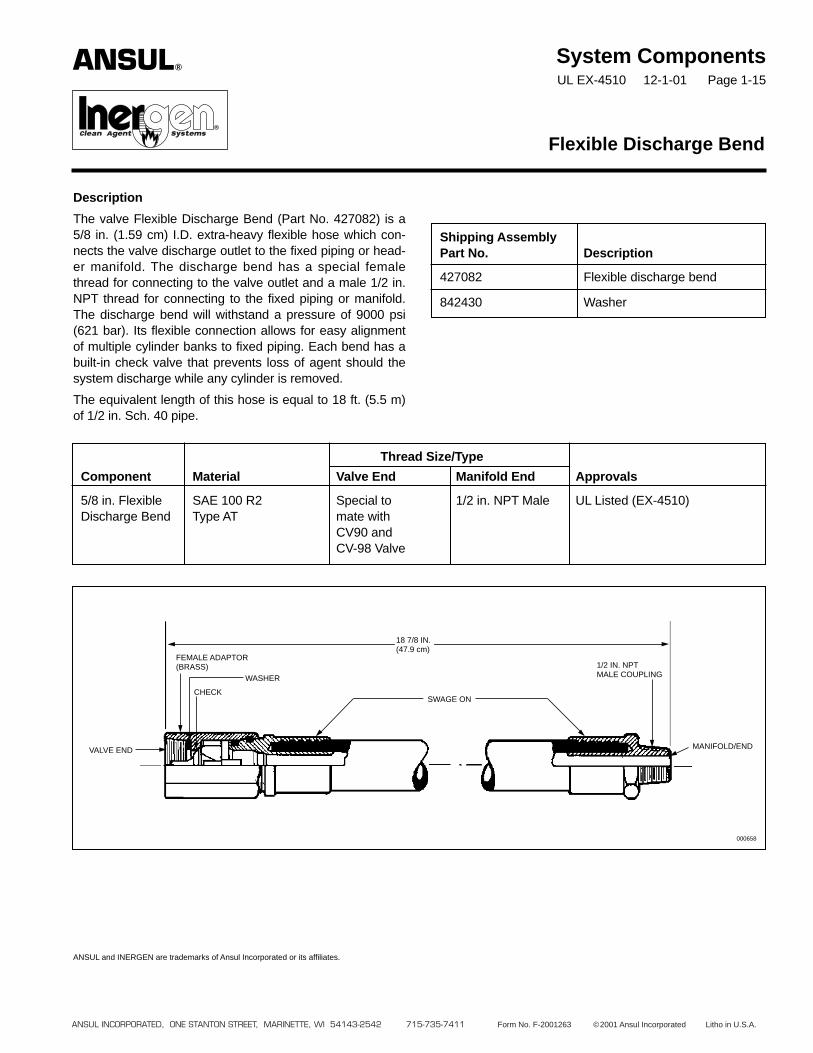
The valve Flexible Discharge Bend (Part No. 427082) is a5/8 in. (1.59 cm) I.D. extra-heavy flexible hose which con-nects the valve discharge outlet to the fixed piping or head-er manifold. The discharge bend has a special femalethread for connecting to the valve outlet and a male 1/2 in.NPT thread for connecting to the fixed piping or manifold.The discharge bend will withstand a pressure of 9000 psi(621 bar). Its flexible connection allows for easy alignmentof multiple cylinder banks to fixed piping. Each bend has abuilt-in check valve that prevents loss of agent should thesystem discharge while any cylinder is removed.
The equivalent length of this hose is equal to 18 ft. (5.5 m)of 1/2 in. Sch. 40 pipe.
ANSUL and INERGEN are trademarks of Ansul Incorporated or its affiliates.
Flexible Discharge Bend
Shipping AssemblyPart No. Description
427082 Flexible discharge bend
842430 Washer
Thread Size/Type
Component Material Valve End Manifold End Approvals
5/8 in. Flexible SAE 100 R2 Special to 1/2 in. NPT Male UL Listed (EX-4510)Discharge Bend Type AT mate with
CV90 andCV-98 Valve
18 7/8 IN.(47.9 cm)
MANIFOLD/END
000658
1/2 IN. NPTMALE COUPLING
FEMALE ADAPTOR(BRASS)
VALVE END
CHECK
WASHER
SWAGE ON
ANSUL®
®
System ComponentsUL EX-4510 12-1-01 Page 1-16
Description
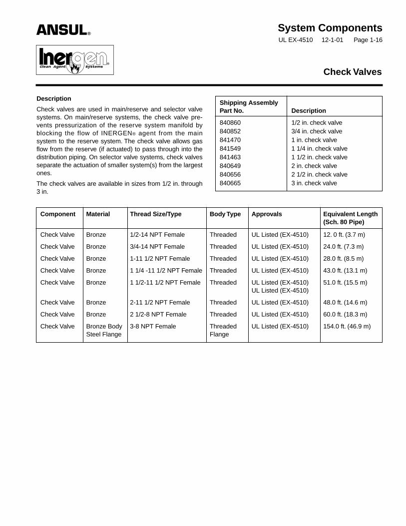
Check valves are used in main/reserve and selector valvesystems. On main/reserve systems, the check valve pre-vents pressurization of the reserve system manifold byblocking the flow of INERGEN® agent from the mainsystem to the reserve system. The check valve allows gasflow from the reserve (if actuated) to pass through into thedistribution piping. On selector valve systems, check valvesseparate the actuation of smaller system(s) from the largestones.
The check valves are available in sizes from 1/2 in. through3 in.
Check Valves
Shipping AssemblyPart No. Description
840860 1/2 in. check valve840852 3/4 in. check valve841470 1 in. check valve841549 1 1/4 in. check valve841463 1 1/2 in. check valve840649 2 in. check valve840656 2 1/2 in. check valve840665 3 in. check valve
Component Material Thread Size/Type Body Type Approvals Equivalent Length(Sch. 80 Pipe)
Check Valve Bronze 1/2-14 NPT Female Threaded UL Listed (EX-4510) 12. 0 ft. (3.7 m)
Check Valve Bronze 3/4-14 NPT Female Threaded UL Listed (EX-4510) 24.0 ft. (7.3 m)
Check Valve Bronze 1-11 1/2 NPT Female Threaded UL Listed (EX-4510) 28.0 ft. (8.5 m)
Check Valve Bronze 1 1/4 -11 1/2 NPT Female Threaded UL Listed (EX-4510) 43.0 ft. (13.1 m)
Check Valve Bronze 1 1/2-11 1/2 NPT Female Threaded UL Listed (EX-4510) 51.0 ft. (15.5 m)UL Listed (EX-4510)
Check Valve Bronze 2-11 1/2 NPT Female Threaded UL Listed (EX-4510) 48.0 ft. (14.6 m)
Check Valve Bronze 2 1/2-8 NPT Female Threaded UL Listed (EX-4510) 60.0 ft. (18.3 m)
Check Valve Bronze Body 3-8 NPT Female Threaded UL Listed (EX-4510) 154.0 ft. (46.9 m)Steel Flange Flange
ANSUL®
®

ANSUL INCORPORATED, ONE STANTON STREET, MARINETTE, WI 54143-2542 715-735-7411 Form No. F-2001264 ©2001 Ansul Incorporated Litho in U.S.A.
Check Valve – Threaded
Dimension A Dimension BValve Size in. (cm) in. (cm)
1/2 in. 3 (7.6) 2 5/8 (6.6)3/4 in. 3 5/8 (9.2) 3 1/8 (7.9)1 in. 4 1/8 (10.4) 3 3/4 (9.5)1 1/4 in. 5 (12.7) 4 1/2 (11.4)1 1/2 in. 5 1/2 (13.9) 5 1/8 (13)2 in. 6 1/2 (16.5) 5 3/4 (14.6)2 1/2 in. 8 (20.3) 6 3/4 (17.1)
Check Valve – Threaded FlangeValve Dimension A Dimension B Dimension CSize in. (cm) in. (cm) in. (cm)
3 in. 11 1/2 (29.2) 15 (38.1) 9 1/2 (24.1)
ANSUL and INERGEN are trademarks of Ansul Incorporated or its affiliates.
A
B
BONNET
BODY
SPRING
CHECK
A
C
B
CHECK
BODY
BONNET
SPRING
001817002254

Description
The header vent plug is used to release low pressure build-up that may occur in a closed system utilizing selectorvalves or check valves. The header vent plug should alsobe installed on the cylinder sides of the check valves onboth main and reserve systems to relieve any pressure thatmay leak past the check valve and accidentally actuate thereserve system while the main system is discharging.
ANSUL and INERGEN are trademarks of Ansul Incorporated or its affiliates.
ANSUL INCORPORATED, ONE STANTON STREET, MARINETTE, WI 54143-2542 715-735-7411 Form No. F-2001265 ©2001 Ansul Incorporated Litho in U.S.A.
System ComponentsUL EX-4510 12-1-01 Page 1-17
Header Vent Plug
Shipping AssemblyPart No. Description
840309 Header vent plug
Component Material Thread Size/Type Approvals
Vent Plug Body: 1/2 in. NPT Male UL Listed (EX-4510)Brass
Spring:Bronze
Seal:Neoprene
SPRING
CHECK SEAL
CHECK CUP
1/2 IN. NPT
000707
STEM
BODY
WASHER
29/32 IN.(2.3 cm)7/8 IN.
(2.2 cm)
ANSUL®
®
System ComponentsUL EX-4510 12-1-01 Page 1-18
Description
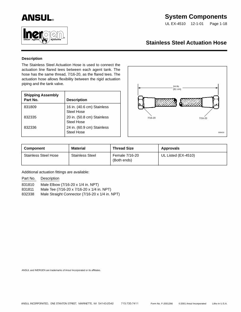
The Stainless Steel Actuation Hose is used to connect theactuation line flared tees between each agent tank. Thehose has the same thread, 7/16-20, as the flared tees. Theactuation hose allows flexibility between the rigid actuationpiping and the tank valve.
Additional actuation fittings are available:
Part No. Description_______ _________
831810 Male Elbow (7/16-20 x 1/4 in. NPT)831811 Male Tee (7/16-20 x 7/16-20 x 1/4 in. NPT)832338 Male Straight Connector (7/16-20 x 1/4 in. NPT)
ANSUL and INERGEN are trademarks of Ansul Incorporated or its affiliates.
Stainless Steel Actuation Hose
Shipping AssemblyPart No. Description
831809 16 in. (40.6 cm) StainlessSteel Hose
832335 20 in. (50.8 cm) StainlessSteel Hose
832336 24 in. (60.9 cm) StainlessSteel Hose
Component Material Thread Size Approvals
Stainless Steel Hose Stainless Steel Female 7/16-20 UL Listed (EX-4510)(Both ends)
24 IN.(61 cm)
7/16-20
000433
7/16-20
ANSUL INCORPORATED, ONE STANTON STREET, MARINETTE, WI 54143-2542 715-735-7411 Form No. F-2001266 ©2001 Ansul Incorporated Litho in U.S.A.
ANSUL®
®�

System ComponentsUL EX-4510 12-1-01 Page 1-19
Description
The pressure reducer/union is required to restrict the flowof INERGEN® agent thus reducing the agent pressuredown stream of the union. The 3000 psi (206.9 bar)NSCWP union contains a stainless steel orifice plate whichis drilled to the specific size hole required based on the flowcalculation.* The orifice plate provides readily visible orificeidentification. The orifice union is available in six sizes:1/2 in., 3/4 in., 1 in., 1 1/4 in., 1 1/2 in., and 2 in. NPT.
All pressure reducer/unions must be installed in the pipingwith the orifice identification tab on the pressure inlet sideof the system. The 1 1/4 in., 1 1/2 in. and 2 in. orificeunions must be installed per the direction of the flow arrowstamped on the body.
Pressure Reducer/Union
Shipping AssemblyPart No. Description A B C
416677 1/2 in. NPT pressure reducer/union 2.06 in. (5.2 cm) 1.18 in. (2.9 cm) 1.95 in. (4.9 cm)416678 3/4 in. NPT pressure reducer/union 2.38 in. (6.1 cm) 1.50 in. (3.8 cm) 2.38 in. (6.1 cm)416679 1 in. NPT pressure reducer/union 2.63 in. (6.7 cm) 1.78 in. (4.5 cm) 2.77 in. (7.0 cm)416680 1 1/4 in. NPT pressure reducer/union 2.94 in. (7.5 cm) 2.04 in. (5.2 cm) 3.31 in. (8.4 cm)416681 1 1/2 in. NPT pressure reducer/union 3.31 in. (8.4 cm) 2.31 in. (5.9 cm) 3.70 in. (9.4 cm)416682 2 in. NPT pressure reducer/union 3.56 in. (9.0 cm) 2.85 in. (7.2 cm) 4.39 in. (11.2 cm)
Component Material Thread Size Approvals
Pressure Reducer/ Body: Forged 1/2, 3/4, 1, UL Listed (EX-4510)Union Steel 1 1/4, 1 1/2,
2 in. NPTOrifice Plate:
StainlessSteel
VISIBLE ORIFICEIDENTIFICATION 002197
DIRECTIONOF FLOW
ANSUL INCORPORATED, ONE STANTON STREET, MARINETTE, WI 54143-2542 715-735-7411 Form No. F-2001267 ©2001 Ansul Incorporated Litho in U.S.A.
C
A
B
ANSUL and INERGEN are trademarks of Ansul Incorporated or its affiliates.
NOTE: Refer to “Nozzle/Pressure Reducer Range Chart” inDesign Section for detailed orifice range information.
* Orifice diameter must be specified when placing order.
ANSUL®
®�
System ComponentsUL EX-4510 12-1-01 Page 1-20
Description
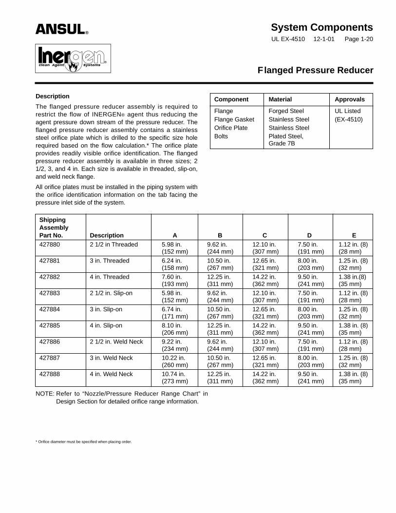
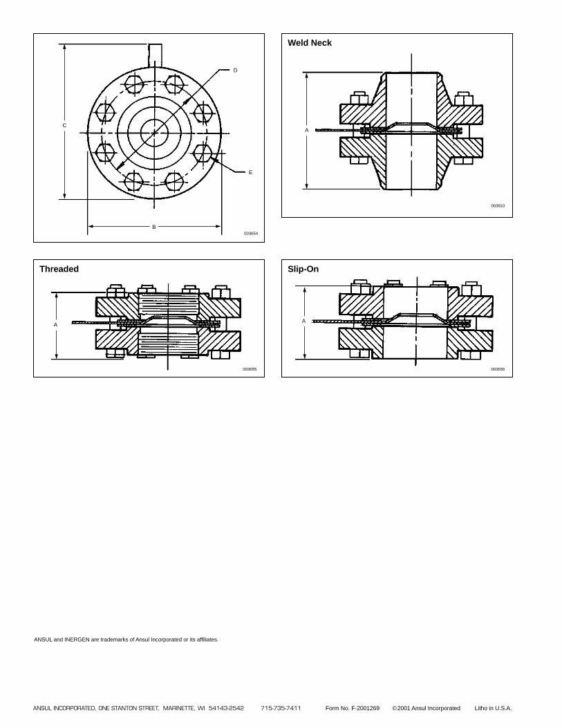
The flanged pressure reducer assembly is required torestrict the flow of INERGEN® agent thus reducing theagent pressure down stream of the pressure reducer. Theflanged pressure reducer assembly contains a stainlesssteel orifice plate which is drilled to the specific size holerequired based on the flow calculation.* The orifice plateprovides readily visible orifice identification. The flangedpressure reducer assembly is available in three sizes; 21/2, 3, and 4 in. Each size is available in threaded, slip-on,and weld neck flange.
All orifice plates must be installed in the piping system withthe orifice identification information on the tab facing thepressure inlet side of the system.
Flanged Pressure Reducer
ShippingAssemblyPart No. Description A B C D E427880 2 1/2 in Threaded 5.98 in. 9.62 in. 12.10 in. 7.50 in. 1.12 in. (8)
(152 mm) (244 mm) (307 mm) (191 mm) (28 mm)
427881 3 in. Threaded 6.24 in. 10.50 in. 12.65 in. 8.00 in. 1.25 in. (8)(158 mm) (267 mm) (321 mm) (203 mm) (32 mm)
427882 4 in. Threaded 7.60 in. 12.25 in. 14.22 in. 9.50 in. 1.38 in.(8)(193 mm) (311 mm) (362 mm) (241 mm) (35 mm)
427883 2 1/2 in. Slip-on 5.98 in. 9.62 in. 12.10 in. 7.50 in. 1.12 in. (8)(152 mm) (244 mm) (307 mm) (191 mm) (28 mm)
427884 3 in. Slip-on 6.74 in. 10.50 in. 12.65 in. 8.00 in. 1.25 in. (8)(171 mm) (267 mm) (321 mm) (203 mm) (32 mm)
427885 4 in. Slip-on 8.10 in. 12.25 in. 14.22 in. 9.50 in. 1.38 in. (8)(206 mm) (311 mm) (362 mm) (241 mm) (35 mm)
427886 2 1/2 in. Weld Neck 9.22 in. 9.62 in. 12.10 in. 7.50 in. 1.12 in. (8)(234 mm) (244 mm) (307 mm) (191 mm) (28 mm)
427887 3 in. Weld Neck 10.22 in. 10.50 in. 12.65 in. 8.00 in. 1.25 in. (8)(260 mm) (267 mm) (321 mm) (203 mm) (32 mm)
427888 4 in. Weld Neck 10.74 in. 12.25 in. 14.22 in. 9.50 in. 1.38 in. (8)(273 mm) (311 mm) (362 mm) (241 mm) (35 mm)
Component Material Approvals
Flange Forged Steel UL ListedFlange Gasket Stainless Steel (EX-4510)Orifice Plate Stainless SteelBolts Plated Steel,
Grade 7B
NOTE: Refer to “Nozzle/Pressure Reducer Range Chart” inDesign Section for detailed orifice range information.
* Orifice diameter must be specified when placing order.
ANSUL®
®�
ANSUL INCORPORATED, ONE STANTON STREET, MARINETTE, WI 54143-2542 715-735-7411 Form No. F-2001269 ©2001 Ansul Incorporated Litho in U.S.A.
Threaded
A
003655
Slip-On
A
003656
Weld Neck
A
003653
C
B003654
D
E
ANSUL and INERGEN are trademarks of Ansul Incorporated or its affiliates.
System ComponentsUL EX-4510 12-1-01 Page 1-21
Description
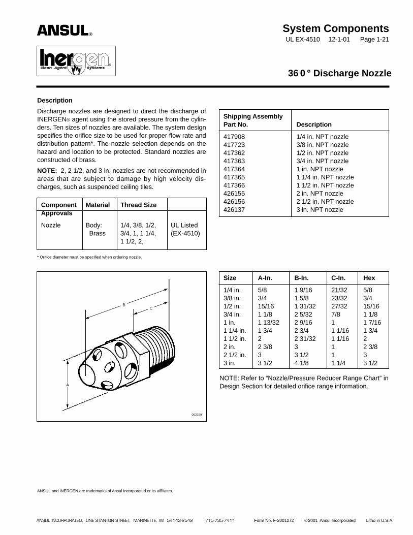
Discharge nozzles are designed to direct the discharge ofINERGEN® agent using the stored pressure from the cylin-ders. Ten sizes of nozzles are available. The system designspecifies the orifice size to be used for proper flow rate anddistribution pattern*. The nozzle selection depends on thehazard and location to be protected. Standard nozzles areconstructed of brass.
NOTE: 2, 2 1/2, and 3 in. nozzles are not recommended inareas that are subject to damage by high velocity dis-charges, such as suspended ceiling tiles.
* Orifice diameter must be specified when ordering nozzle.
ANSUL and INERGEN are trademarks of Ansul Incorporated or its affiliates.
360° Discharge Nozzle
Shipping AssemblyPart No. Description
417908 1/4 in. NPT nozzle417723 3/8 in. NPT nozzle417362 1/2 in. NPT nozzle417363 3/4 in. NPT nozzle417364 1 in. NPT nozzle417365 1 1/4 in. NPT nozzle417366 1 1/2 in. NPT nozzle426155 2 in. NPT nozzle426156 2 1/2 in. NPT nozzle426137 3 in. NPT nozzle
Size A-In. B-In. C-In. Hex
1/4 in. 5/8 1 9/16 21/32 5/83/8 in. 3/4 1 5/8 23/32 3/41/2 in. 15/16 1 31/32 27/32 15/163/4 in. 1 1/8 2 5/32 7/8 1 1/81 in. 1 13/32 2 9/16 1 1 7/161 1/4 in. 1 3/4 2 3/4 1 1/16 1 3/41 1/2 in. 2 2 31/32 1 1/16 22 in. 2 3/8 3 1 2 3/82 1/2 in. 3 3 1/2 1 33 in. 3 1/2 4 1/8 1 1/4 3 1/2
ANSUL INCORPORATED, ONE STANTON STREET, MARINETTE, WI 54143-2542 715-735-7411 Form No. F-2001272 ©2001 Ansul Incorporated Litho in U.S.A.
BC
A
002199
NOTE: Refer to “Nozzle/Pressure Reducer Range Chart” inDesign Section for detailed orifice range information.
ANSUL®
®�
Component Material Thread SizeApprovals
Nozzle Body: 1/4, 3/8, 1/2, UL ListedBrass 3/4, 1, 1 1/4, (EX-4510)
1 1/2, 2,
System ComponentsUL EX-4510 12-1-01 Page 1-22
Description
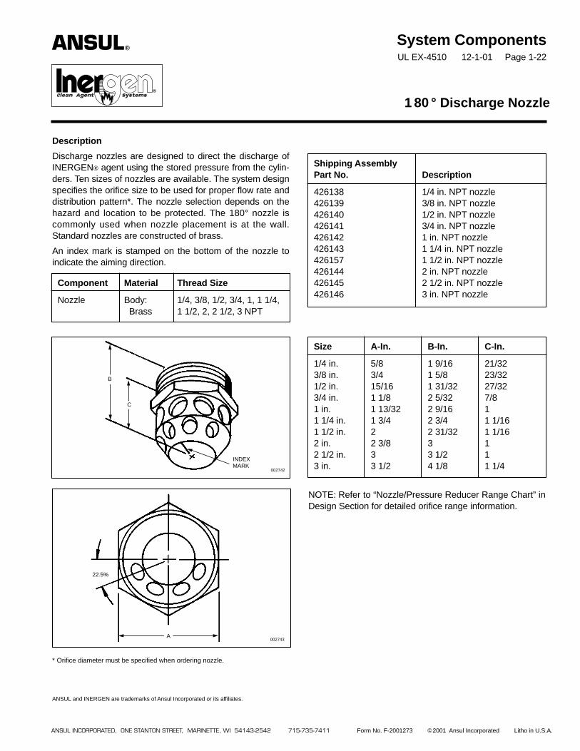
Discharge nozzles are designed to direct the discharge ofINERGEN® agent using the stored pressure from the cylin-ders. Ten sizes of nozzles are available. The system designspecifies the orifice size to be used for proper flow rate anddistribution pattern*. The nozzle selection depends on thehazard and location to be protected. The 180° nozzle iscommonly used when nozzle placement is at the wall.Standard nozzles are constructed of brass.
An index mark is stamped on the bottom of the nozzle toindicate the aiming direction.
* Orifice diameter must be specified when ordering nozzle.
ANSUL and INERGEN are trademarks of Ansul Incorporated or its affiliates.
180° Discharge Nozzle
Shipping AssemblyPart No. Description
426138 1/4 in. NPT nozzle426139 3/8 in. NPT nozzle426140 1/2 in. NPT nozzle426141 3/4 in. NPT nozzle426142 1 in. NPT nozzle426143 1 1/4 in. NPT nozzle426157 1 1/2 in. NPT nozzle426144 2 in. NPT nozzle426145 2 1/2 in. NPT nozzle426146 3 in. NPT nozzle
ANSUL INCORPORATED, ONE STANTON STREET, MARINETTE, WI 54143-2542 715-735-7411 Form No. F-2001273 ©2001 Ansul Incorporated Litho in U.S.A.
C
002742
002743
Component Material Thread Size
Nozzle Body: 1/4, 3/8, 1/2, 3/4, 1, 1 1/4,Brass 1 1/2, 2, 2 1/2, 3 NPT
Size A-In. B-In. C-In.
1/4 in. 5/8 1 9/16 21/323/8 in. 3/4 1 5/8 23/321/2 in. 15/16 1 31/32 27/323/4 in. 1 1/8 2 5/32 7/81 in. 1 13/32 2 9/16 11 1/4 in. 1 3/4 2 3/4 1 1/161 1/2 in. 2 2 31/32 1 1/162 in. 2 3/8 3 12 1/2 in. 3 3 1/2 13 in. 3 1/2 4 1/8 1 1/4
22.5%
A
B
INDEXMARK
NOTE: Refer to “Nozzle/Pressure Reducer Range Chart” inDesign Section for detailed orifice range information.
ANSUL®
®�

System ComponentsUL EX-4510 12-1-01 Page 1-23
Description
The INERGEN® system nozzle deflector shield is used tocontrol the pattern of the discharge of the INERGEN agent.The deflector shield helps keep the agent discharge awayfrom false ceiling tiles and fragile light fixtures, avoidingdamage to them.
The deflector shields are constructed of steel and paintedwith a cameo cream colored paint. They are available infive sizes.
Nozzle Deflector Shield
Component Material Approvals
Nozzle Steel UL Listed (EX-4510)DeflectorShield
Shipping A B C D EAssembly Inlet Length of Overall Deflector CouplingPart No. NPT Coupling Length O.D. O.D.
417708 1/2 in. 1 7/8 in. 3 in. 3 3/8 in. 1 1/8 in.(4.8 cm) (7.6 cm) (8.6 cm) (2.9 cm)
417711 3/4 in. 2 in. 3 1/4 in. 3 3/8 in. 1 3/8 in.(5.1 cm) (8.3 cm) (8.6 cm) (3.5 cm)
417714 1 in. 2 3/8 in. 3 13/16 in. 4 7/8 in. 1 3/4 in.(6.0 cm) (9.7 cm) (12.4 cm) (4.4 cm)
417717 1 1/4 in. 2 5/8 in. 4 3/16 in. 4 7/8 in. 2 1/4 in.(6.7 cm) (10.6 cm) (12.4 cm) (5.7 cm)
417720 1 1/2 in. 3 1/8 in. 4 29/32 in. 5 21/32 in. 2 1/2 in.(7.9 cm) (12.5 cm) (14.4 cm) (6.4 cm)
D
B
A
C
E
ANSUL INCORPORATED, ONE STANTON STREET, MARINETTE, WI 54143-2542 715-735-7411 Form No. F-2001274 ©2001 Ansul Incorporated Litho in U.S.A.
003651
NOTE: There are no deflector shields available for the 2, 2 1/2, or 3 in. models.
ANSUL and INERGEN are trademarks of Ansul Incorporated or its affiliates.
ANSUL®
®�

System ComponentsUL EX-4510 7-15-02 Page 1-24
REV. 1
Description
The cylinder bracketing is designed to rigidly support theinstalled INERGEN® agent cylinders. The bracketing compo-nents are constructed of heavy structural steel. Bracketassemblies are available in modules for two to six cylindersand can also be connected together for any combinationover six. Bracketing can be assembled to support single row,double row or back-to-back rows of cylinders. Bracketingcomponents are painted with a red enamel coating. Uprights
and back frame assemblies can be bolted or weldedtogether, whichever makes the installation moreconvenient.
Cylinder Bracketing
Component Material Approvals
Bracketing Steel UL Listed(EX-4510)
Shipping AssemblyPart No. Description
845122 575 ft.3 (16.3 m3) cylinder strap (single cylinder)845245 575 ft.3 (16.3 m3) cylinder channel with nuts and bolts (single cylinder)879638 Back frame assembly (2 cylinder)879639 Back frame assembly (3 cylinder)879640 Back frame assembly (4 cylinder)879641 Back frame assembly (5 cylinder)879642 Back frame assembly (6 cylinder)873257 Upright, for 575 ft.3 (16.3 m3) cylinders (used either for right side, left side or center
(center upright required when connecting seven or more cylinders in a row))873553 Single row or back-to-back row bracket foot (left side)873554 Single row or back-to-back row bracket foot (right side)873555 Double row bracket foot (left side)873556 Double row bracket foot (right side)418508 Center upright foot879413 Connector (required to hook together back frames for seven or more cylinders)418502 13 in. (33.0 cm) carriage bolt with nut (for single row 575 ft.3 (16.3 m3) cylinders)418503 27 in. (68.6 cm) carriage bolt with nut (for double row 575 ft.3 (16.3 m3) cylinders)873091 Cylinder clamp (2 cylinders)873092 Cylinder clamp (3 cylinders)871683 Weigh rail support – single row871682 Weigh rail support – double row871684 Weigh rail support – back-to-back rows423027 Weigh rail support back-to-back double row
ANSUL®
®

Multi-Cylinder Single Cylinder
UPRIGHT
BACK FRAME
CYLINDER CLAMP
CARRIAGE BOLTWITH NUT
RIGHTBRACKET FOOT
LEFTBRACKET FOOT
CHANNEL
002200
CLAMP
WEIGH RAIL SUPPORT
ANSUL and INERGEN are trademarks of Ansul Incorporated or its affiliates.
ANSUL INCORPORATED, ONE STANTON STREET, MARINETTE, WI 54143-2542 715-735-7411 Form No. F-2001275-1 ©2002 Ansul Incorporated Litho in U.S.A.

System ComponentsUL EX-4510 12-1-01 Page 1-25
Description
The pressure switch is operated by the INERGEN™ agentpressure when the system is discharged. The pressureswitch can be used to open or close electrical circuits toeither shut down equipment or turn on lights or alarms. Thedouble pole, single throw (DPST) pressure switch is con-structed with a gasketed, water tight housing. The housingis constructed of malleable iron, painted red. A 1/4 in. NPTpressure inlet is used to connect the 1/4 in. pipe from theINERGEN system.
BAKELITE is a trademark of Union Carbide Corp.
ANSUL and INERGEN are trademarks of Ansul Incorporated or its affiliates.
The pressure switch can be installed either before or afterthe pressure reducer in the distribution piping.
Minimum operating pressure is 50 PSI (3.5 bar).
Pressure Switch – DPST
Shipping AssemblyPart No. Description
846250 Pressure switch – DPST
Component Material Thread Size/Type Electrical Rating Approvals
Pressure Switch Switch: Conduit Inlet: 3/4 in. NPT Female 2 HP – 240 VAC/ UL Listed (EX-4510)DPST BAKELITE Pressure Inlet: 1/4 in. NPT Female 480 VAC
Housing: 2 HP – 250 VDC,Malleable 30A – 250V AC/DCIron 5A – 480V AC/DC
Piston:Brass
Cover:Brass
MALLEABLE IRONFINISH – RED PAINT
BRASS RESETPLUNGER
MOISTURE-PROOFJOINT
GASKET NUT
“O” RING GASKET
NAMEPLATE
DOUBLE POLE –HEAVY DUTYTOGGLE SWITCHWITH FULLYENCLOSEDBAKELITE BASE
BRASS PISTON
PISTON “O” RINGGASKET
1/4 IN. UNION
3/4 IN.ELECTRICALCONDUITOUTLETS
TOPOWER
TO ELECTRICALEQUIPMENT TOBE CONTROLLED
1/4 IN. PIPEFROM CYLINDERS
000716
004593
3 5/8 IN.(9.2 cm)
2 7/8 IN.(7.3 cm)
4 9/16 IN.(11.5 cm)
ANSUL INCORPORATED, ONE STANTON STREET, MARINETTE, WI 54143-2542 715-735-7411 Form No. F-2001276 ©2001 Ansul Incorporated Litho in U.S.A.
19/64 IN. (7.5 mm)MOUNTING HOLE –TYP. 2 PLACES
ANSUL®
®�
The pressure switch can be installed either before or afterthe pressure reducer in the distribution piping.
Minimum operating pressure is 50 PSI (3.5 bar)
Description
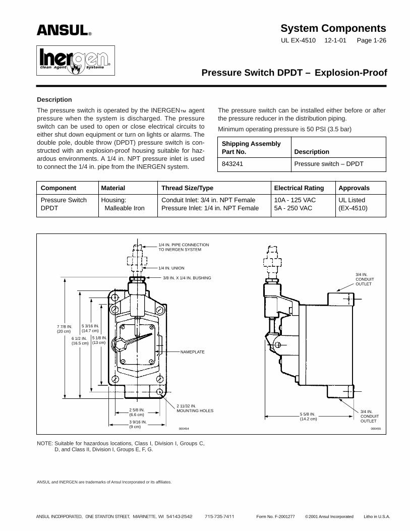
The pressure switch is operated by the INERGEN™ agentpressure when the system is discharged. The pressureswitch can be used to open or close electrical circuits toeither shut down equipment or turn on lights or alarms. Thedouble pole, double throw (DPDT) pressure switch is con-structed with an explosion-proof housing suitable for haz-ardous environments. A 1/4 in. NPT pressure inlet is usedto connect the 1/4 in. pipe from the INERGEN system.
NOTE: Suitable for hazardous locations, Class I, Division I, Groups C,D, and Class II, Division I, Groups E, F, G.
ANSUL and INERGEN are trademarks of Ansul Incorporated or its affiliates.
System ComponentsUL EX-4510 12-1-01 Page 1-26
Pressure Switch DPDT – Explosion-Proof
Shipping AssemblyPart No. Description
843241 Pressure switch – DPDT
Component Material Thread Size/Type Electrical Rating Approvals
Pressure Switch Housing: Conduit Inlet: 3/4 in. NPT Female 10A - 125 VAC UL ListedDPDT Malleable Iron Pressure Inlet: 1/4 in. NPT Female 5A - 250 VAC (EX-4510)
1/4 IN. PIPE CONNECTIONTO INERGEN SYSTEM
1/4 IN. UNION
3/8 IN. X 1/4 IN. BUSHING
NAMEPLATE
2 11/32 IN.MOUNTING HOLES
7 7/8 IN.(20 cm)
6 1/2 IN.(16.5 cm)
5 3/16 IN.(14.7 cm)
5 1/8 IN.(13 cm)
3 9/16 IN.(9 cm)
5 5/8 IN.(14.2 cm)
2 5/8 IN.(6.6 cm)
3/4 IN.CONDUITOUTLET
000455000454
3/4 IN.CONDUITOUTLET
ANSUL INCORPORATED, ONE STANTON STREET, MARINETTE, WI 54143-2542 715-735-7411 Form No. F-2001277 ©2001 Ansul Incorporated Litho in U.S.A.
ANSUL®
®�
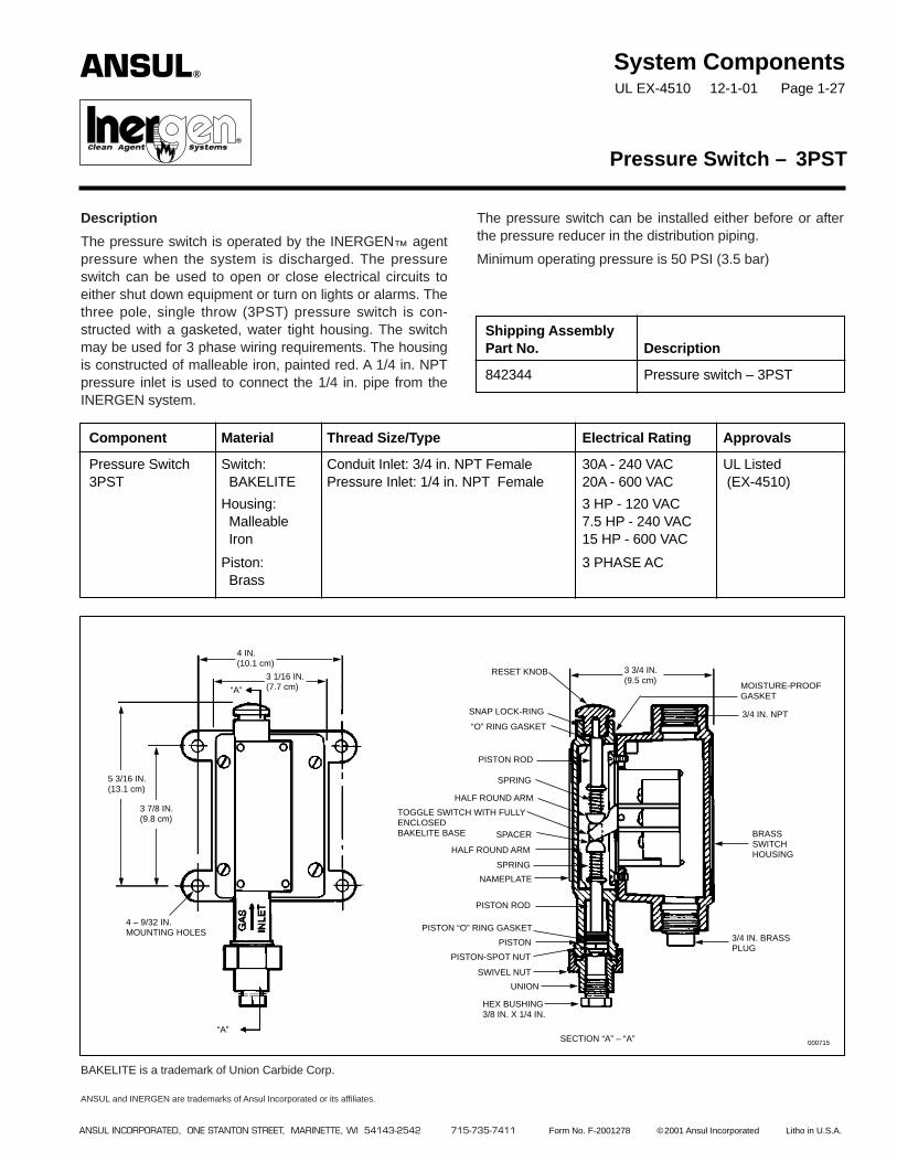
The pressure switch can be installed either before or afterthe pressure reducer in the distribution piping.
Minimum operating pressure is 50 PSI (3.5 bar)
Description
The pressure switch is operated by the INERGEN™ agentpressure when the system is discharged. The pressureswitch can be used to open or close electrical circuits toeither shut down equipment or turn on lights or alarms. Thethree pole, single throw (3PST) pressure switch is con-structed with a gasketed, water tight housing. The switchmay be used for 3 phase wiring requirements. The housingis constructed of malleable iron, painted red. A 1/4 in. NPTpressure inlet is used to connect the 1/4 in. pipe from theINERGEN system.
BAKELITE is a trademark of Union Carbide Corp.
ANSUL and INERGEN are trademarks of Ansul Incorporated or its affiliates.
System ComponentsUL EX-4510 12-1-01 Page 1-27
Pressure Switch – 3PST
Shipping AssemblyPart No. Description
842344 Pressure switch – 3PST
Component Material Thread Size/Type Electrical Rating Approvals
Pressure Switch Switch: Conduit Inlet: 3/4 in. NPT Female 30A - 240 VAC UL Listed3PST BAKELITE Pressure Inlet: 1/4 in. NPT Female 20A - 600 VAC (EX-4510)
Housing: 3 HP - 120 VACMalleable 7.5 HP - 240 VACIron 15 HP - 600 VAC
Piston: 3 PHASE ACBrass
RESET KNOB
SPRING
HALF ROUND ARM
SNAP LOCK-RING
“O” RING GASKET
PISTON ROD
UNION
SWIVEL NUT
NAMEPLATE
SPRING
HALF ROUND ARM
3/4 IN. NPT
3/4 IN. BRASSPLUG
HEX BUSHING3/8 IN. X 1/4 IN.
SECTION “A” – “A”
PISTON ROD
PISTON-SPOT NUT
PISTON
PISTON “O” RING GASKET
BRASSSWITCHHOUSING
TOGGLE SWITCH WITH FULLYENCLOSEDBAKELITE BASE
MOISTURE-PROOFGASKET
“A”000715
“A”
4 – 9/32 IN.MOUNTING HOLES
5 3/16 IN.(13.1 cm)
3 7/8 IN.(9.8 cm)
4 IN.(10.1 cm)
3 1/16 IN.(7.7 cm)
3 3/4 IN.(9.5 cm)
SPACER
ANSUL INCORPORATED, ONE STANTON STREET, MARINETTE, WI 54143-2542 715-735-7411 Form No. F-2001278 ©2001 Ansul Incorporated Litho in U.S.A.
ANSUL®
®�
System ComponentsUL EX-4510 12-1-01 Page 1-28
Description
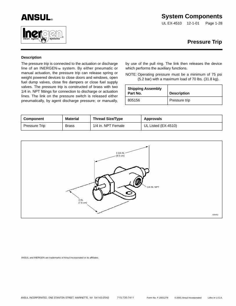
The pressure trip is connected to the actuation or dischargeline of an INERGEN™ system. By either pneumatic ormanual actuation, the pressure trip can release spring orweight powered devices to close doors and windows, openfuel dump valves, close fire dampers or close fuel supplyvalves. The pressure trip is constructed of brass with two1/4 in. NPT fittings for connection to discharge or actuationlines. The link on the pressure switch is released eitherpneumatically, by agent discharge pressure; or manually,
by use of the pull ring. The link then releases the devicewhich performs the auxiliary functions.
NOTE: Operating pressure must be a minimum of 75 psi(5.2 bar) with a maximum load of 70 lbs. (31.8 kg).
Pressure Trip
Shipping AssemblyPart No. Description
805156 Pressure trip
Component Material Thread Size/Type Approvals
Pressure Trip Brass 1/4 in. NPT Female UL Listed (EX-4510)
ANSUL and INERGEN are trademarks of Ansul Incorporated or its affiliates.
3 3/4 IN.(9.5 cm)
1/4 IN. NPT
000452
3 IN.(7.6 cm)
ANSUL INCORPORATED, ONE STANTON STREET, MARINETTE, WI 54143-2542 715-735-7411 Form No. F-2001279 ©2001 Ansul Incorporated Litho in U.S.A.
ANSUL®
®�
System ComponentsUL EX-4510 12-1-01 Page 1-29
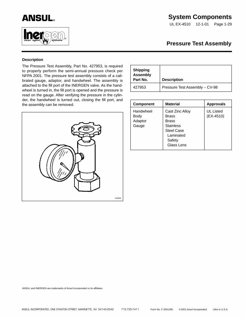
Description
The Pressure Test Assembly, Part No. 427953, is requiredto properly perform the semi-annual pressure check perNFPA 2001. The pressure test assembly consists of a cali-brated gauge, adaptor, and handwheel. The assembly isattached to the fill port of the INERGEN valve. As the hand-wheel is turned in, the fill port is opened and the pressure isread on the gauge. After verifying the pressure in the cylin-der, the handwheel is turned out, closing the fill port, andthe assembly can be removed.
ANSUL and INERGEN are trademarks of Ansul Incorporated or its affiliates.
Pressure Test Assembly
ShippingAssemblyPart No. Description
427953 Pressure Test Assembly – CV-98
Component Material Approvals
Handwheel Cast Zinc Alloy UL Listed Body Brass (EX-4510)Adaptor BrassGauge Stainless
Steel CaseLaminatedSafetyGlass Lens
ANSUL INCORPORATED, ONE STANTON STREET, MARINETTE, WI 54143-2542 715-735-7411 Form No. F-2001280 ©2001 Ansul Incorporated Litho in U.S.A.
003686
ANSUL®
®�

System ComponentsUL EX-4510 12-1-01 Page 1-30
Description
The ‘‘MAIN’’ nameplate is available for labeling compo-nents and/or remote pull stations to distinguish them fromreserve system components. The nameplate is furnishedwith four mounting holes for ease of installation.
ANSUL and INERGEN are trademarks of Ansul Incorporated or its affiliates.
Nameplate – MAIN
Shipping AssemblyPart No. Description
841942 Nameplate – MAIN
Component Material Mounting Hole Size Approvals
Nameplate Aluminum 13/64 in. (.52 cm) UL Listed (EX-4510)
MAIN
5 1/2 IN.(13.9 cm)
4 7/8 IN.(12.4 cm)
1 7/8 IN.(4.7 cm)
2 1/2 IN.(6.4 cm)
5/16 IN.(.8 cm)
5/16 IN.(.8 cm)
PART NO. 41942
4 – 13/64 IN. (.5 cm)DIAMETER HOLES
ANSUL INCORPORATED, ONE STANTON STREET, MARINETTE, WI 54143-2542 715-735-7411 Form No. F-2001283 ©2001 Ansul Incorporated Litho in U.S.A.
ANSUL®
®�
System ComponentsUL EX-4510 12-1-01 Page 1-31
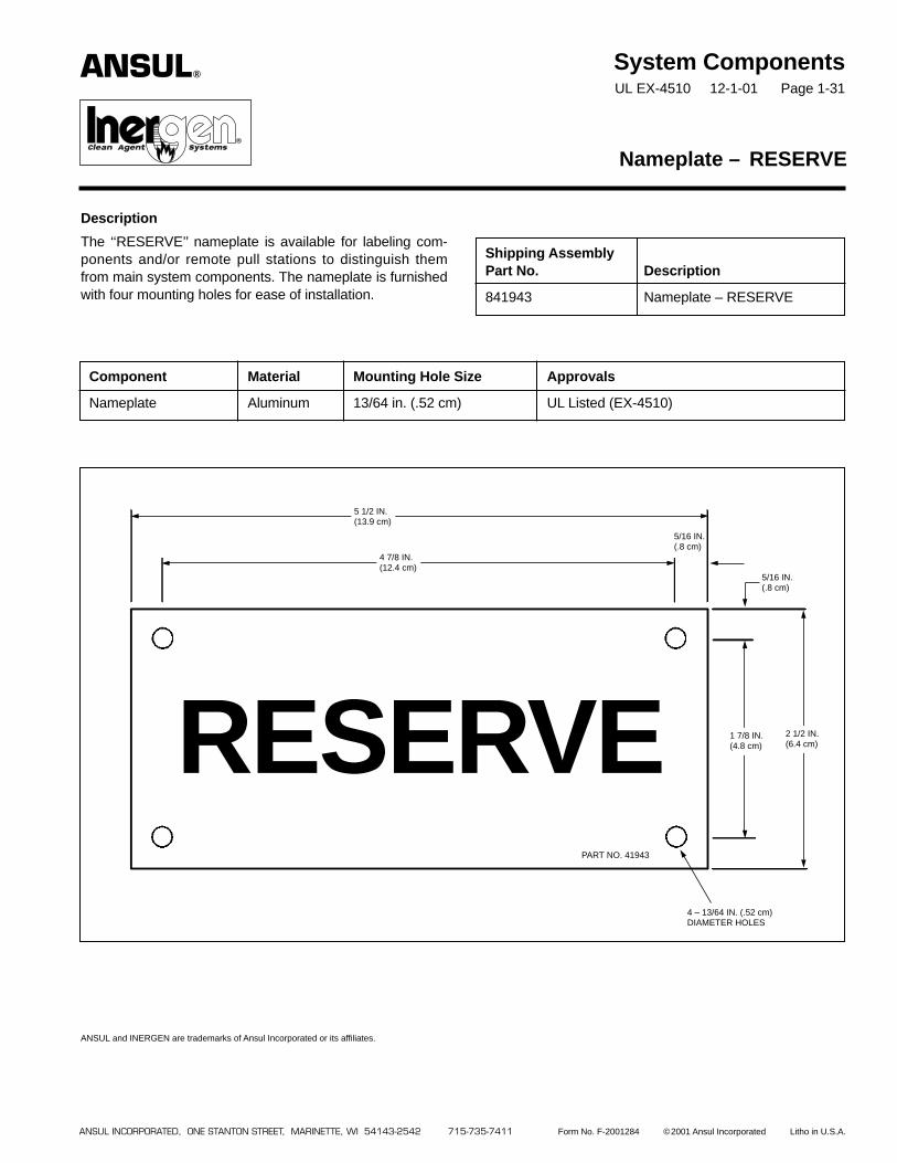
Description
The ‘‘RESERVE’’ nameplate is available for labeling com-ponents and/or remote pull stations to distinguish themfrom main system components. The nameplate is furnishedwith four mounting holes for ease of installation.
ANSUL and INERGEN are trademarks of Ansul Incorporated or its affiliates.
Nameplate – RESERVE
Shipping AssemblyPart No. Description
841943 Nameplate – RESERVE
Component Material Mounting Hole Size Approvals
Nameplate Aluminum 13/64 in. (.52 cm) UL Listed (EX-4510)
RESERVE
5 1/2 IN.(13.9 cm)
4 7/8 IN.(12.4 cm)
1 7/8 IN.(4.8 cm)
2 1/2 IN.(6.4 cm)
5/16 IN.(.8 cm)
5/16 IN.(.8 cm)
PART NO. 41943
4 – 13/64 IN. (.52 cm)DIAMETER HOLES
ANSUL INCORPORATED, ONE STANTON STREET, MARINETTE, WI 54143-2542 715-735-7411 Form No. F-2001284 ©2001 Ansul Incorporated Litho in U.S.A.
ANSUL®
®�

System ComponentsUL EX-4510 12-1-01 Page 1-32
Description
The warning plate is available for mounting inside the haz-ard area to warn the personnel to vacate the hazard areawhen the alarm sounds. The warning plate is furnished withfour mounting holes for ease of installation. The plate isconstructed of aluminum.
ANSUL and INERGEN are trademarks of Ansul Incorporated or its affiliates.
Warning Plate – Inside Room With Alarm
Shipping AssemblyPart No. Description
416265 Warning Plate – inside roomwith alarm
Component Material Mounting Hole Size Approvals
Warning Plate Aluminum 1/4 in. (.64 cm) UL Listed (EX-4510)
ANSUL INCORPORATED, ONE STANTON STREET, MARINETTE, WI 54143-2542 715-735-7411 Form No. F-2001285 ©2001 Ansul Incorporated Litho in U.S.A.
WHEN ALARM SOUNDSVACATE AT ONCEINERGEN™ AGENTBEING RELEASED
12.00
7.00
LABEL NO. 416265
002746
ANSUL®
®�
®�

System ComponentsUL EX-4510 12-1-01 Page 1-33
Description
The warning plate is available for mounting outside thehazard area to warn the personnel that the space is pro-tected by an INERGEN™ system and no one should enterafter a discharge without being properly protected. Thewarning plate is furnished with four mounting holes for easeof installation.
ANSUL and INERGEN are trademarks of Ansul Incorporated or its affiliates.
Warning Plate – Outside Room Without Alarm
Shipping AssemblyPart No. Description
416266 Warning Plate – outsideroom
Component Material Mounting Hole Size Approvals
Warning Plate Aluminum 7/32 in. (.56 cm) UL Listed (EX-4510)
WARNINGTHIS SPACE IS PROTECTED BY AN INERGEN®
FIRE SUPPRESSION SYSTEM.
WHEN SYSTEM IS DISCHARGED AS A RESULTOF FIRE, CAUTION MUST BE TAKEN TO AVOIDEXPOSURE TO PRODUCTS OF COMBUSTION.
DO NOT ENTER WITHOUT APPROVED SELF-CONTAINED BREATHING APPARATUS ORUNTIL VENTILATION HAS BEEN OPERATEDFOR AT LEAST 15 MINUTES.
8.00
7.00
LABEL NO. 416266
ANSUL INCORPORATED, ONE STANTON STREET, MARINETTE, WI 54143-2542 715-735-7411 Form No. F-2001286 ©2001 Ansul Incorporated Litho in U.S.A.
002747
ANSUL®
®�
®�

PRODUCT NAME
INERGEN® Fire Suppression System
ENVIRONMENTAL IMPACT
INERGEN agent is a mixture of threenaturally occurring gases: nitrogen, argon,and carbon dioxide. As INERGEN agent isderived from gases present in the earth’satmosphere, it exhibits no ozone depletingpotential, does not contribute to globalwarming, nor does it contribute uniquechemical species with extended atmosphericlifetimes. Because INERGEN agent iscomposed of atmospheric gases, it does notpose the problems of toxicity associated withthe chemically derived Halon alternativeagents.
PRODUCT DESCRIPTION
The INERGEN Fire Suppression System,manufactured by Ansul, is an engineeredsystem utilizing a fixed nozzle agent distribu-tion network. The system is designed andinstalled in accordance with the National FireProtection Association (NFPA) Standard2001, ‘‘Clean Agent Fire ExtinguishingSystems.’’ When properly designed, theINERGEN system will extinguish surfaceburning fire in Class A, B, and C hazards bylowering the oxygen content below the levelthat supports combustion.
INERGEN agent has also been tested byFMRC for inerting capabilities. Those testshave shown that INERGEN agent, at designconcentrations between 40% and 50%, hassuccessfully inerted mixtures of propane/air,and methane/air.
The system can be actuated by detectionand control equipment for automatic systemoperation along with providing local andremote manual operation as needed.Accessories are used to provide alarms,ventilation control, door closures, or otherauxiliary shutdown or functions.
When INERGEN agent is discharged into aroom, it introduces the proper mixture ofgases that will allow a person to breathe in areduced oxygen atmosphere.
A system installation and maintenancemanual is available containing information onsystem components and proceduresconcerning design, operation, inspection,maintenance, and recharge.
The system is installed and serviced byauthorized distributors that are trained by themanufacturer.
Basic Use – The INERGEN system is partic-ularly useful for suppressing fires in hazardswhere an electrically non-conductive mediumis essential or desirable; where clean-up ofother agents present a problem; or where the
INERGEN® FIRESUPPRESSIONSYSTEMSDATA SHEET
200 BARSYSTEMSPECIFICATIONS
hazard is normally occupied and requires anon-toxic agent.
The following are typical hazards protectedby INERGEN systems:
• Computer rooms
• Subfloors
• Tape storage
• Telecommunication/Switchgear
• Vaults
• Process equipment
• All normally occupied or unoccupied elec-tronic areas where equipment is either verysensitive or irreplaceable
Composition and Materials – The basicsystem consists of extinguishing agent storedin high strength alloy steel cylinders. Varioustypes of actuators, either manual or auto-matic, are available for release of the agentinto the hazard area. The agent is distributedand discharged into the hazard area througha network of piping and nozzles. Each nozzleis drilled with a fixed orifice designed todeliver a uniform discharge to the protectedarea. On large hazards, where three or morecylinders are required, a screwed or weldedpipe manifold assembly is employed. Thecylinder(s) is connected to the distributionpiping or the manifold by means of a flexibledischarge bend and check valve assembly.
Additional equipment includes – Controlpanels, releasing devices, remote manualpull stations, corner pulleys, door closures,pressure trips, bells and alarms, and pneu-matic switches. All or some are requiredwhen designing a total system.
INERGEN Agent – INERGEN agent is amixture of three inerting (oxygen diluting)gases: 52% nitrogen, 40% argon, and 8%carbon dioxide. INERGEN gas extinguishesfire by lowering the oxygen content below thelevel that supports combustion. WhenINERGEN agent is discharged into a room, itintroduces the proper mixture of gases thatstill allow a person to breathe in a reducedoxygen atmosphere. It actually enhances thebody’s ability to assimilate oxygen. Thenormal atmosphere in a room contains 21%oxygen and less than 1% carbon dioxide. Ifthe oxygen content is reduced below 15%,most ordinary combustibles will cease toburn. INERGEN agent will reduce the oxygencontent to approximately 12.5% whileincreasing the carbon dioxide content toabout 3%. The increase in the carbon dioxidecontent increases a person’s respiration rateand the body’s ability to absorb oxygen.Simply stated, the human body is stimulatedby the carbon dioxide to breathe more deeplyand rapidly to compensate for the loweroxygen content of the atmosphere.
Cylinders – The cylinders are constructed,tested, and marked in accordance withapplicable Department of Transportation(DOT) specifications. As a minimum, thecylinders must meet the requirements ofDOT 3AA3000.
Cylinder Assembly – The cylinder assemblyis of steel construction with a red standardfinish. One size is available. Each cylinder isequipped with a pressure seat-type valveequipped with gauge. The valve is construct-ed of forged brass and is attached to thecylinder providing a leak tight seal. The valvealso includes a safety pressure relief devicewhich provides relief at 4000-4480 psi(276-309 bar) per CGA test method. Cylindercharging pressure is 2900 psi at 70 °F(200 bar at 21 °C). The cylinders are shippedwith a maintenance record card and shippingcap attached. The cap is attached to thethreaded collar on the neck of each cylinderto protect the valve while in transit. The cylin-der serial number and date of manufactureare stamped near the neck of each cylinder.
Electric Actuator – Electric actuation of anagent cylinder is accomplished by anelectric actuator interfaced through anAUTOPULSE® Control System. This actuatorcan be used in hazardous environmentswhere the ambient temperature range isbetween 32 °F and 130 °F (0 °C and 54 °C).In auxiliary or override applications, a manuallever actuator can be installed on top of theactuator.
Manual or Pneumatic Actuators – Threetypes of manual actuators are available forlever actuation on the cylinder valve. Manualactuation is accomplished by pulling thehand lever on the actuator.
Detection System – The AUTOPULSEControl System is used where an automaticelectronic control system is required toactuate the INERGEN system. This controlsystem is used to control a single fixed firesuppression or alarm system based oninputs received from fire detection devices.The detection circuits can be configuredusing cross, counting, independent or priori-ty-zone (counting) concepts. The controlsystem has been tested to the applicableFCC Rules and Regulations for Class AComputing devices.
ANSUL®

Nozzles – Nozzles are designed to direct thedischarge of INERGEN agent using thestored pressure from the cylinders. Nozzlesare available in either 360° or 180° dischargepatterns. The system design specifies thenozzle and orifice size to be used for properflow rate and distribution pattern. The nozzleselection depends on the hazard and loca-tion to be protected.
Pressure Reducer – The pressure reduceris required in the distribution piping to restrictthe flow of INERGEN agent, thus reducingthe agent pressure down stream of thereducer. The pressure reducer contains astainless steel orifice plate which is drilled tothe specific size hole required based on thehydraulic calculation. The orifice plate pro-vides readily visible orifice identification. Thepressure reducer is available in nine sizes:1/2 in., 3/4 in., 1 in., 1 1/4 in., 1 1/2 in., 2 in.,2 1/2 in., 3 in., and 4 in. NPT.
Pipe and Fittings – System manifold pipingmust be constructed to withstand a mini-mum pressure of 3000 psi (206.9 bar).Distribution piping downstream from the ori-fice union must be constructed to withstandthe maximum downstream pressure asdetermined by the flow calculation.
Limitations – The INERGEN system mustbe designed and installed within the guide-lines of the manufacturer’s design, installa-tion, operation, inspection, recharge, andmaintenance manual. The ambient temper-ature limitations are 32 °F to 130 °F (–0 °Cto 54 °C). All AUTOPULSE Control Systemsare designed for indoor applications and fortemperature ranges between 32 °F and120 °F (0 °C and 49 °C).
TECHNICAL DATA
Applicable Standards: The INERGENsystem complies with NFPA Standard 2001,Standard for Clean Agent Fire ExtinguishingSystems, and EPA Program SNAP,Significant New Alternate Policy.
System is listed by UnderwritersLaboratories, Inc. (UL).
Agent is listed and approved by UnderwritersLaboratories, Inc. (UL) and Factory MutualResearch Corporation (FMRC).
INSTALLATIONS
All system components and accessoriesmust be installed by personnel trained by themanufacturer. All installations must be per-formed according to the guidelines stated inthe manufacturer’s design, installation,operation, inspection, recharge, andmaintenance manual.
AVAILABILITY AND COST
Availability – INERGEN Systems are soldand serviced through a network of indepen-dent distributors located in many countries.
Cost – Cost varies with type of systemspecified, size, and design.
PRODUCT WARRANTY
Warranty – The components of the firesuppression system supplied by Ansul Inc.(‘‘Ansul’’) are warranted to you as the originalpurchaser for one year from the date ofdelivery against defects in workmanship andmaterial. Ansul will replace or repair anyAnsul supplied components, which, in itsopinion, are defective and have not beentampered with or subjected to misuse,abuse, or exposed to highly corrosive condi-tions provided that written notice of thealleged defect shall have been given toAnsul within 30 days after discovery thereofand prior to the expiration of one year afterdelivery, and further provided that if Ansul soinstructs, such article or part thereof ispromptly returned to Ansul with shippingcharges prepaid.
Disclaimer of Warranty and Limitation ofDamage – The warranty described above isthe only one given by Ansul concerning thissystem. ANSUL MAKES NO OTHERWARRANTIES OF ANY KIND, WHETHEREXPRESS OR IMPLIED, INCLUDING THEWARRANTIES OF MERCHANTABILITYAND FITNESS FOR PARTICULARPURPOSE. ANSUL’S MAXIMUM RESPON-SIBILITY FOR ANY CLAIMS WHETHER INCONTRACT, TORT, NEGLIGENCE,BREACH OF WARRANTY, OR STRICTLIABILITY SHALL BE LIMITED TO THEPURCHASE PRICE OF THE SYSTEM.UNDER NO CIRCUMSTANCES SHALLANSUL BE RESPONSIBLE FOR SPECIAL,CONSEQUENTIAL, OR INCIDENTALDAMAGES OF ANY KIND. Ansul does notassume or authorize any other person toassume for it any additional liability inconnection with the sale of this system.
For repairs, parts, and service of the Ansulfire suppression system, contact a localAnsul international representative, or AnsulIncorporated, Marinette, WI 54143-2542,715-735-7411.
FALSE DISCHARGE WARRANTY
Subject to the conditions set forth below,Ansul will, as purchaser’s sole remedy,replace INERGEN gas and pay reasonablecosts to recharge the INERGEN/Detectionand Control System where, in Ansul’s opin-ion, the discharge has occurred due to adefect in the material or workmanship of theproducts provided by Ansul. This warranty isextended only to the original purchaser of theINERGEN/Detection and Control System andonly for a period of one year from the date ofinstallation of the INERGEN/Detection andControl System.
Ansul will only replace INERGEN gas andpay reasonable costs to recharge theINERGEN/Detection and Control Systemwhere the discharge occurs due to a defectin the material or workmanship of theproducts provided by Ansul. For example,Ansul will not be responsible for dischargesdue to faulty maintenance or installation orservice, intentional acts by the owner or thirdparties, or circumstances over which Ansulhas no control. Ansul will not be responsiblefor discharges of the INERGEN/Detectionand Control System which occur if theINERGEN/Detection and Control System,as initially installed, has been altered ormodified.
This warranty shall be effective only if theoriginal purchaser maintains a semi-annualservice agreement for the INERGEN/Detection and Control System with anAuthorized Ansul Distributor from the date ofinstallation. This warranty covers only thoseINERGEN/Detection and Control Systemspurchased from Ansul or its AuthorizedDistributors and only those INERGEN/Detection and Control Systems which incor-porate and use only hardware and compo-nents, including detection and controldevices manufactured, sold, or approved byAnsul. This warranty may not be assigned ortransferred to others.
Ansul Product Services Department must benotified within three days of the discharge ofthe INERGEN/Detection and Control Systemand must approve the cost of INERGEN gasand recharge service in advance.
Except as provided above, ANSUL MAKESNO WARRANTIES OF ANY KIND,WHETHER EXPRESSED OR IMPLIED,INCLUDING THE WARRANTIES OFMERCHANTABILITY AND FITNESS FOR APARTICULAR PURPOSE, UNDER NOCIRCUMSTANCE SHALL ANSUL HAVEANY LIABILITY FOR CONSEQUENTIAL,INCIDENTAL, SPECIAL OR SIMILARDAMAGES. ANSUL SHALL HAVE NOLIABILITY FOR ANY DAMAGES DUE TODELAY IN RECHARGING THE‘‘INERGEN’’/DETECTION AND CONTROLSYSTEM. ANSUL’S MAXIMUM LIABILITYFOR DIRECT DAMAGES IS LIMITED TOTHE REPLACEMENT OF INERGEN GASAND REASONABLE COSTS TORECHARGE THE ‘‘INERGEN’’/DETECTIONAND CONTROL SYSTEM.
This warranty is not effective unless AnsulForm No. F-9346 is completed and returnedto Ansul within 10 days of the commissioningof the INERGEN/Detection and ControlSystem.
MAINTENANCE
Maintenance is a vital step in the perfor-mance of a fire suppression system. Assuch, it must be performed by an authorizedAnsul distributor in accordance with NFPA2001 and the manufacturer’s design, installa-tion, recharge, and maintenance manual.When replacing components on the Ansulsystem, use only Ansul approved parts.
TECHNICAL SERVICES
For information on the proper design andinstallation, contact a local internationalauthorized INERGEN System distributor.The Ansul applications engineering depart-ment is also available to answer design andinstallation questions. Call 715-735-7411.
ANSUL, AUTOPULSE and INERGEN are trademarks ofAnsul Incorporated or its affiliates.
ANSUL INCORPORATED, ONE STANTON STREET, MARINETTE, WI 54143-2542 715-735-7411 Form No.F-2001292-1 ©2002 Ansul Incorporated Litho in U.S.A.

APPLICATION
INERGEN® extinguishing agent used inAnsul engineered systems is particularlyuseful for hazards where an electrical, non-conductive medium is essential or desirable;where clean-up of other agents presents aproblem; where hazard obstructions requirethe use of a gaseous agent; or where thehazard is normally occupied and requires anon-toxic agent.
The following are typical hazards protectedby INERGEN systems:
• Computer rooms
• Subfloors
• Tape storage
• Telecommunications/Switchgear
• Vaults
• Process equipment
• All normally occupied or unoccupied areaswhere electronic equipment is either verysensitive or irreplaceable
ENVIRONMENTAL IMPACT
INERGEN agent is a mixture of three natu-rally occurring gases: nitrogen, argon andcarbon dioxide. As INERGEN agent isderived from gases present in the earth’satmosphere, it exhibits no ozone depletingpotential, does not contribute to global warm-ing, nor does it contribute unique chemicalspecies with extended atmospheric lifetimes.Because INERGEN agent is composed ofatmospheric gases, it does not pose theproblems of toxicity associated with thechemically derived Halon alternative agents.
DESCRIPTION
INERGEN agent is a plentiful, non-corrosivegas that does not support combustion norreact with most substances. INERGEN agentcontains only naturally-occurring gases whichhave no impact on the ozone or the environ-ment in general. INERGEN agent is a mix-ture of three inerting (oxygen diluting) gases:52% nitrogen, 40% argon, and 8% carbondioxide. INERGEN agent extinguishes fire bylowering the oxygen content below the levelthat supports combustion. When INERGENagent is discharged into a room, it introducesthe proper mixture of gases that still allow a
INERGEN® FIRESUPPRESSIONSYSTEMSDATA SHEET
EXTINGUISHINGAGENT
person to breathe in a reduced oxygenatmosphere. It actually enhances the body’sability to assimilate oxygen. The normalatmosphere in a room contains approximate-ly 21% oxygen and less than 1% carbondioxide. If the oxygen content is reducedbelow 15%, most ordinary combustibles willnot burn. INERGEN agent will reduce theoxygen content to approximately 12.5% whileincreasing the carbon dioxide content toabout 3%. The increase in the carbon dioxidecontent increases a person’s respiration rateand the body’s ability to absorb oxygen.Simply stated, the human body is stimulatedby the carbon dioxide to breathe more deeplyand rapidly to compensate for the lower oxy-gen content of the atmosphere.
PERFORMANCE
INERGEN is an effective fire extinguishingagent that can be used on many types offires. INERGEN extinguishing system unitsare designed for total flooding protectionagainst Class A surface burning, Class Bflammable liquid, and Class C fires occurringwithin an enclosure by lowering the oxygencontent below the level that supports com-bustion.
INERGEN agent has been tested by FMRCfor inerting capabilities. Those tests haveshown that INERGEN agent, at design con-centrations between 40% and 50%, has suc-cessfully inerted mixtures of propane/air, andmethane/air.
PHYSICAL PROPERTIES OF INERGEN
Specific gravity:0.085 lbs./cu. ft. (1.36 kg/m3)
Vapor density:1.1 (Air = 1)
Approximate molecular weight:34
APPROVAL
INERGEN agent complies with the NFPAStandard 2001, Standard for Clean AgentFire Extinguishing Systems and EPAProgram SNAP, Significant New AlternatePolicy.
Agent is listed and approved by UnderwritersLaboratories, Inc. (UL) and Factory MutualResearch Corporation (FMRC).
Containers meet the applicable Departmentof Transportation (DOT) specifications.
ANSUL and INERGEN are trademarks of AnsulIncorporated or its affiliates.
ANSUL®
ANSUL INCORPORATEDMARINETTE, WI 54143-2542715-735-7411 Form No. F-200045-1 ©2002 Ansul Incorporated Litho in U.S.A.
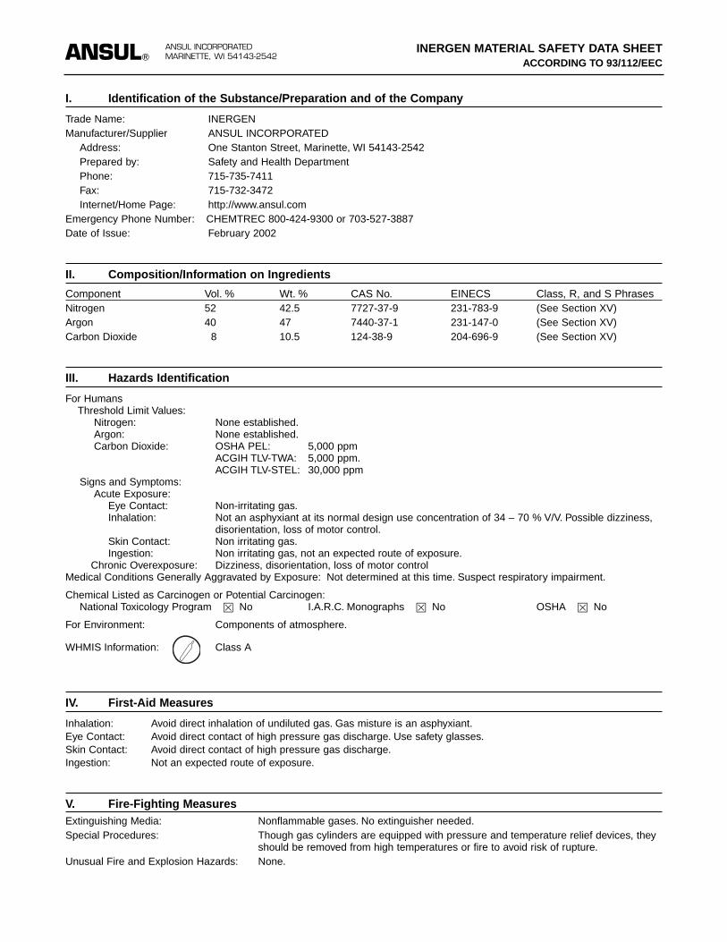
I. Identification of the Substance/Preparation and of the Company
Trade Name: INERGENManufacturer/Supplier ANSUL INCORPORATED
Address: One Stanton Street, Marinette, WI 54143-2542Prepared by: Safety and Health DepartmentPhone: 715-735-7411Fax: 715-732-3472Internet/Home Page: http://www.ansul.com
Emergency Phone Number: CHEMTREC 800-424-9300 or 703-527-3887Date of Issue: February 2002
II. Composition/Information on Ingredients
Component Vol. % Wt. % CAS No. EINECS Class, R, and S PhrasesNitrogen 52 42.5 7727-37-9 231-783-9 (See Section XV)Argon 40 47 7440-37-1 231-147-0 (See Section XV)Carbon Dioxide 8 10.5 124-38-9 204-696-9 (See Section XV)
III. Hazards Identification
For HumansThreshold Limit Values:
Nitrogen: None established.Argon: None established.Carbon Dioxide: OSHA PEL: 5,000 ppm
ACGIH TLV-TWA: 5,000 ppm.ACGIH TLV-STEL: 30,000 ppm
Signs and Symptoms:Acute Exposure:
Eye Contact: Non-irritating gas.Inhalation: Not an asphyxiant at its normal design use concentration of 34 – 70 % V/V. Possible dizziness,
disorientation, loss of motor control.Skin Contact: Non irritating gas.Ingestion: Non irritating gas, not an expected route of exposure.
Chronic Overexposure: Dizziness, disorientation, loss of motor controlMedical Conditions Generally Aggravated by Exposure: Not determined at this time. Suspect respiratory impairment.
Chemical Listed as Carcinogen or Potential Carcinogen:National Toxicology Program � No I.A.R.C. Monographs � No OSHA � No
For Environment: Components of atmosphere.
WHMIS Information: Class A
IV. First-Aid Measures
Inhalation: Avoid direct inhalation of undiluted gas. Gas misture is an asphyxiant.Eye Contact: Avoid direct contact of high pressure gas discharge. Use safety glasses.Skin Contact: Avoid direct contact of high pressure gas discharge.Ingestion: Not an expected route of exposure.
V. Fire-Fighting MeasuresExtinguishing Media: Nonflammable gases. No extinguisher needed.Special Procedures: Though gas cylinders are equipped with pressure and temperature relief devices, they
should be removed from high temperatures or fire to avoid risk of rupture.Unusual Fire and Explosion Hazards: None.
ANSULANSUL INCORPORATEDMARINETTE, WI 54143-2542
INERGEN MATERIAL SAFETY DATA SHEETACCORDING TO 93/112/EEC
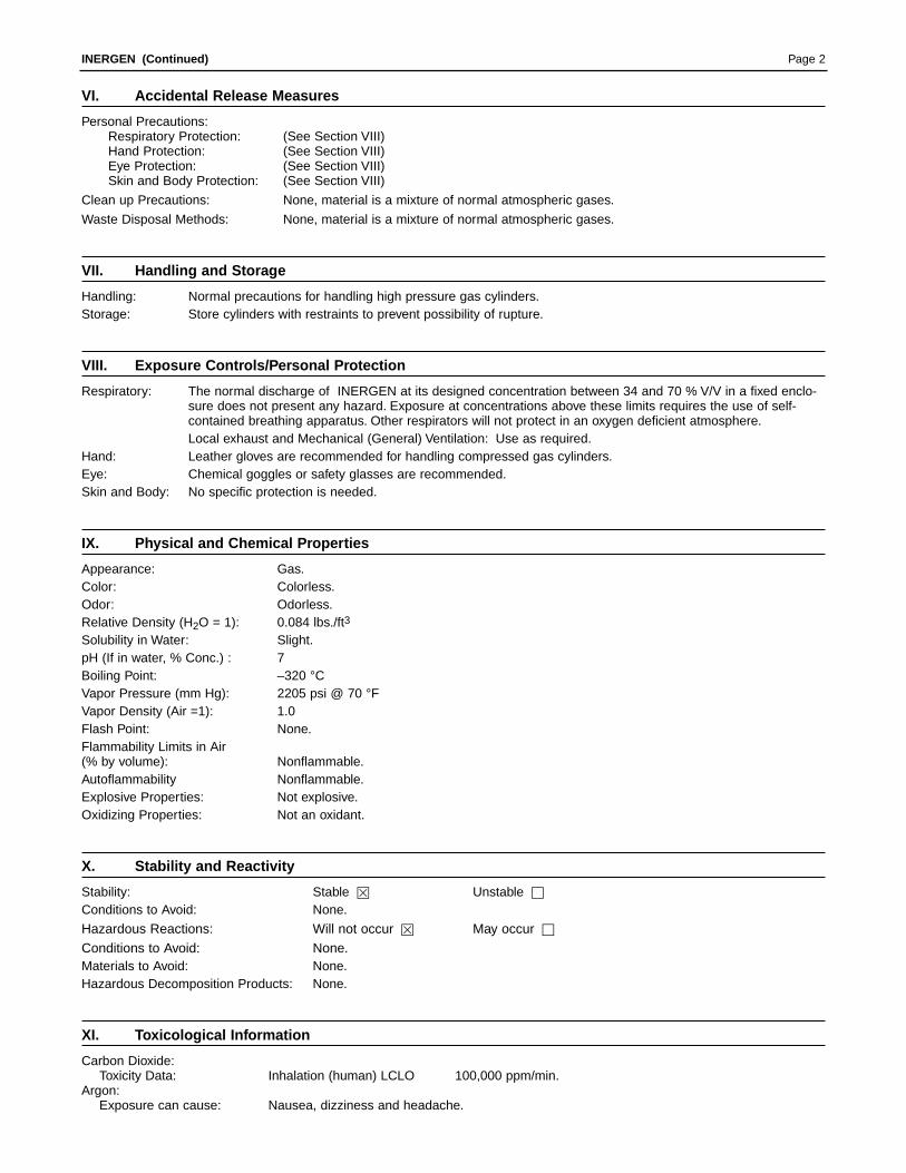
VI. Accidental Release Measures
Personal Precautions:Respiratory Protection: (See Section VIII)Hand Protection: (See Section VIII)Eye Protection: (See Section VIII)Skin and Body Protection: (See Section VIII)
Clean up Precautions: None, material is a mixture of normal atmospheric gases.
Waste Disposal Methods: None, material is a mixture of normal atmospheric gases.
VII. Handling and Storage
Handling: Normal precautions for handling high pressure gas cylinders.Storage: Store cylinders with restraints to prevent possibility of rupture.
VIII. Exposure Controls/Personal Protection
Respiratory: The normal discharge of INERGEN at its designed concentration between 34 and 70 % V/V in a fixed enclo-sure does not present any hazard. Exposure at concentrations above these limits requires the use of self-contained breathing apparatus. Other respirators will not protect in an oxygen deficient atmosphere.Local exhaust and Mechanical (General) Ventilation: Use as required.
Hand: Leather gloves are recommended for handling compressed gas cylinders.Eye: Chemical goggles or safety glasses are recommended.Skin and Body: No specific protection is needed.
IX. Physical and Chemical Properties
Appearance: Gas.Color: Colorless.Odor: Odorless.Relative Density (H2O = 1): 0.084 lbs./ft3
Solubility in Water: Slight.pH (If in water, % Conc.) : 7Boiling Point: –320 °CVapor Pressure (mm Hg): 2205 psi @ 70 °FVapor Density (Air =1): 1.0Flash Point: None.Flammability Limits in Air(% by volume): Nonflammable.Autoflammability Nonflammable.Explosive Properties: Not explosive.Oxidizing Properties: Not an oxidant.
X. Stability and Reactivity
Stability: Stable � Unstable □
Conditions to Avoid: None.
Hazardous Reactions: Will not occur � May occur □
Conditions to Avoid: None.Materials to Avoid: None.Hazardous Decomposition Products: None.
XI. Toxicological Information
Carbon Dioxide:Toxicity Data: Inhalation (human) LCLO 100,000 ppm/min.
Argon:Exposure can cause: Nausea, dizziness and headache.
Page 2INERGEN (Continued)

XII. Ecological Information
Mobility: Atmospheric gases.Absorption/Desorption: Atmospheric gases.Degradability: Atmospheric gases.Biotic and Abiotic Degradation: Atmospheric gases.Aerobic and Anaerobic Degradation: Atmospheric gases.Persistence: Atmospheric gases.Accumulation: Atmospheric gases.Bioaccumulation Potential: Atmospheric gases.Biomagnification: Atmospheric gases.Short and Long Term Effects on:
Ecotoxicity Atmospheric gases.Aquatic Organisms: Atmospheric gases.Soil Organisms: Atmospheric gases.Plants and Terrestrial animals: Atmospheric gases.
Other Adverse Effects: Atmospheric gases.Ozone Depletion Potential: Atmospheric gases.Photochemical Ozone Creation Potential: Atmospheric gases.Global Warming Potential: Contains carbon dioxide, a Global Warming gas.Effects on Waste Water Treatment Plants: Atmospheric gases.
XIII. Disposal Considerations
Dispose of in Compliance with local, state, and national regulations.
XIV. Transport Information
Hazard Class: Compressed Gas N.O.S. (mixture of nitrogen, compressed, argon and carbon dioxide), Class 2.2, UN1956.Label: Nonflammable gas.Emergency response page number: 126; EMS (Intl): 2-04.For additional transport information, contact Ansul Incorporated.
XV. Regulatory Information
EU Classification: Nonflammable gas.R Phrases: None.
9 Keep container in a well-ventilated place.Threshold Limit Values:
Nitrogen: None established.Argon: None established.Carbon Dioxide: OSHA PEL: 5,000 ppm
ACGIH TLV-TWA: 5,000 ppm.ACGIH TLV-STEL: 30,000 ppm.
EINECS Status: All components are included in EINECS inventories.Restrictions on Marketing and Use: NoneRefer to any other national measures that may be relevant.
XVI. Other Information
None known.
XVII. Disclaimer
THE ABOVE INFORMATION IS BELIEVED TO BE CORRECT BUT DOES NOT PURPORT TO BE ALL INCLUSIVE ANDSHALL BE USED ONLY AS A GUIDE. ANSUL SHALL NOT BE HELD LIABLE FOR ANY DAMAGE RESULTING FROMHANDLING OR FROM CONTACT WITH THE ABOVE PRODUCT.
Page 3INERGEN (Continued)
ANSUL INCORPORATED, ONE STANTON STREET, MARINETTE, WI 54143-2542 715-735-7411 Form No. F-9759-2 ©2002 Ansul Incorporated Litho in U.S.A.
ANSUL is a trademark of Ansul Incorporated or its affiliates.
MSDS available at http://www.ansul.com

SECTION IIIUL EX-4510 12-1-01 Page 3-1
INERGEN® AGENTINERGEN is a plentiful, non-corrosive gas that does notsupport combustion nor react with most substances.INERGEN agent contains only naturally-occurring gaseswhich have no impact on the ozone or the environment ingeneral. INERGEN agent is a mixture of three inerting (oxy-gen diluting) gases: 52% nitrogen, 40% argon, and 8% car-bon dioxide (see MSDS in Section II). INERGEN extin-guishes fire by lowering the oxygen content below the levelthat supports combustion. When INERGEN agent is dis-charged into a room, it introduces the proper mixture ofgases that allow a person to breathe in a reduced oxygenatmosphere. It actually enhances the body’s ability to accu-mulate oxygen. The normal atmosphere in a room containsapproximately 21% oxygen and less than 1% carbon diox-ide. If the oxygen content is reduced below 15%, most ordi-nary combustibles will not burn. INERGEN agent willreduce the oxygen content to approximately 12.5% whileincreasing the carbon dioxide content to about approxi-mately 3%. The increase in the carbon dioxide contentincreases a person’s respiration rate and the body’s abilityto absorb oxygen. Simply stated, the human body is stimu-lated by the carbon dioxide to breathe more deeply andrapidly to compensate for the lower oxygen content of theatmosphere.
PERSONAL SAFETYProper INERGEN system design requires that the designconcentrations fall within a design window that limits theupper and lower requirements of both oxygen and carbondioxide. INERGEN agent has acceptable toxicity for use inoccupied spaces when used as specified in the UnitedStates Environmental Protection Agency (EPA) proposedSignificant New Alternative Policy (SNAP) program rulesand NFPA 2001, “Clean Agent Fire Extinguishing Systems.”When design concentrations are in this window, no adverseaffects will take place on the human respiratory system.Any exposure outside of these limits requires the use ofself-contained breathing apparatus. Respirators will notfunction in oxygen deficient atmospheres. Because of thedecomposed products of combustion generated during anactual fire and extinguishment, it is a good safety rule toventilate the hazard for at least 15 minutes before enteringor if entry is required sooner, wear an approved self-con-tained breathing apparatus.
Refer to NFPA 2001, 2000 edition, Paragraph 1-6.1.3, “InertGas Clean Agents,” for detailed exposure conditions.
HMIS 1-0-0/very cold discharge. Contents under highpressure.
Avoid direct contact of the cold, high pressure dischargeand avoid direct inhalation of undiluted gas.
WARNINGAVOID EXPOSURE TO VAPORS, FUMES,AND PRODUCTS OF COMBUSTION.
TYPE OF SYSTEMTotal flooding is the approved type of system available. Atotal flooding system normally consists of a fixed supply ofINERGEN connected to piping with nozzles to direct theagent into an enclosed hazard space. In a total floodingsystem, the enclosure around the hazard must be tightenough to hold the required percentage of INERGEN con-centration for a period of time to extinguish the fire.
TYPES OF ACTUATIONThere are three basic types of actuation for the INERGENsystems: pneumatic, mechanical, and electrical.
ElectricalAutomatic electrical actuation of the cylinder valve,through an approved control panel, can be accomplishedby using an HF actuator for the CV-98 valve. The actuatoris energized by an electric signal from the detection/controlpanel. When using the electric actuator, pneumatic ormechanical actuating devices can also be attached as asecondary means of actuation. When using electric actua-tion, a means of manual release shall also be provided.
MechanicalMechanical actuation is accomplished by a lever actuatormounted on top of the cylinder valve or other actuators. Byrotating the lever on the actuator, either locally or from aremote pull station, the cylinder valve can be opened,allowing the INERGEN to discharge through the piping andnozzles.
General Information
ANSUL®
®
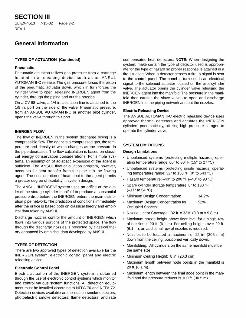
SECTION IIIUL EX-4510 7-15-02 Page 3-2
REV. 1
General Information
TYPES OF ACTUATION (Continued)
PneumaticPneumatic actuation utilizes gas pressure from a cartridgelocated in a releasing device such as an ANSULAUTOMAN II-C release. The gas pressure forces the pistonof the pneumatic actuator down, which in turn forces thecylinder valve to open, releasing INERGEN agent from thecylinder, through the piping and out the nozzles.
On a CV-98 valve, a 1/4 in. actuation line is attached to the1/8 in. port on the side of the valve. Pneumatic pressure,from an ANSUL AUTOMAN II-C or another pilot cylinder,opens the valve through this port.
INERGEN FLOWThe flow of INERGEN in the system discharge piping is acompressible flow. The agent is a compressed gas, the tem-perature and density of which changes as the pressure inthe pipe decreases. The flow calculation is based on classi-cal energy conservation considerations. For simple sys-tems, an assumption of adiabatic expansion of the agent issufficient. The ANSUL flow calculation program, however,accounts for heat transfer from the pipe into the flowingagent. The consideration of heat input to the agent permitsa greater degree of flexibility in system design.
The ANSUL “INERGEN” system uses an orifice at the out-let of the storage cylinder manifold to produce a substantialpressure drop before the INERGEN enters the main distrib-ution pipe network. The prediction of conditions immediatelyafter the orifice is based both on classical theory and empir-ical data taken by ANSUL.
Discharge nozzles control the amount of INERGEN whichflows into various portions of the protected space. The flowthrough the discharge nozzles is predicted by classical the-ory enhanced by empirical data developed by ANSUL.
TYPES OF DETECTIONThere are two approved types of detection available for theINERGEN system: electronic control panel and electricreleasing device.
Electronic Control PanelElectric actuation of the INERGEN system is obtainedthrough the use of electronic control systems which monitorand control various system functions. All detection equip-ment must be installed according to NFPA 70 and NFPA 72.Detection devices available are: ionization smoke detectors,photoelectric smoke detectors, flame detectors, and rate
compensated heat detectors. NOTE: When designing thesystem, make certain the type of detector used is appropri-ate for the type of hazard so proper response is attained in afire situation. When a detector senses a fire, a signal is sentto the control panel. The panel in turn sends an electricalsignal to the solenoid actuator located on the pilot cylindervalve. The actuator opens the cylinder valve releasing theINERGEN agent into the manifold. The pressure in the mani-fold then causes the slave valves to open and dischargeINERGEN into the piping network and out the nozzles.
Electric Releasing DeviceThe ANSUL AUTOMAN II-C electric releasing device usesapproved thermal detectors and actuates the INERGENcylinders pneumatically, utilizing high pressure nitrogen tooperate the cylinder valve.
SYSTEM LIMITATIONS
Design Limitations
• Unbalanced systems (protecting multiple hazards) oper-ating temperature range: 60° to 80° F (15° to 27 °C)
• Unbalanced systems (protecting single hazards) operat-ing temperature range: 32° to 130 °F (0° to 543 °C)
• Hazard temperature: –40° to 200 °F (–40° to 93 °C)
• Spare cylinder storage temperature: 0° to 130 °F(–17° to 54 °C)
• Minimum Design Concentration: 34.2%
• Maximum Design Concentration for 52%Occupied Spaces:
• Nozzle Linear Coverage: 32 ft. x 32 ft. (9.8 m x 9.8 m)
• Maximum nozzle height above floor level for a single rowof nozzles is 20 ft. (6.1 m). For ceiling heights over 20 ft.(6.1 m), an additional row of nozzles is required.
• Nozzles to be located a maximum of 12 in. (305 mm)down from the ceiling, positioned vertically down.
• Manifolding: All cylinders on the same manifold must bethe same size
• Minimum Ceiling Height: 8 in. (20.3 cm)
• Maximum length between node points in the manifold is20 ft. (6.1 m).
• Maximum length between the final node point in the man-ifold and the pressure reducer is 100 ft. (30.5 m).

SECTION IIIUL EX-4510 7-15-02 Page 3-3
REV. 1
General Information
SYSTEM LIMITATIONS (Continued)
Design Limitations (Continued)
• Length from pressure reducer to first tee must be a mini-mum of 10 pipe diameters.
• Discharge time for 90% of the agent shall be more than30 seconds after actuation of the system but not toexceed 138 seconds.
• 1/4 in. and 3/8 in. pipe is allowed in Schedule 40 only.Schedule 80 or 160 is not allowed in these pipe sizes.
• The maximum allowed split % of INERGEN agentthrough a tee is 95%:5%.
• On a side/thru tee, the side outlet must always be thesmallest of the two splits.
• Other than what is stated previously, there are no orienta-tion or critical length requirements necessary for teearrangements.
Flow Calculation Limitations
• Minimum Nozzle Pressure 375 psi (2586 kPa)Pressure:
• Maximum Pipe Volume vs. 56%Cylinder Volume:
• For unbalanced systems, UL/ULC ratio of nozzle orificediameter to pipe diameter shall be a minimum of 11.5%to a maximum of 70%.
• For unbalanced systems, UL/ULC ratio of pressure reduc-er orifice to inlet pipe diameter shall be a minimum of13% to a maximum of 55%.
• In an unbalanced piping system, the time lag in reachingpeak pressure at the various nozzles in the system mayvary. If the variation is beyond certain programmed limits,an error message is generated indicating that the time toreach pressure at one or more nozzles is too long. Thiscondition may result if the length of pipe leading to a noz-zle is extremely long compared to the length of pipe lead-ing to one or more other nozzles in the system.
• For unbalanced systems, the INERGEN Designer 5.0.1Computer Design Program is the only calculation methodto be used with Ansul Engineered INERGEN systems.
• The INERGEN Designer 5.0.1 Computer Design Programis designed for a +70 °F (+21 °C) cylinder operating/storage temperature. Therefore, the cylinder operating/storage temperature must be in the range of +60 °F to+80 °F (+15.5 °C to 26.7 °C) for a single unbalanced sys-tem protecting two or more separate hazards. If the cylin-der operating/storage temperature is outside this range,an insufficient or excessive quantity of agent may be dis-charged from one or more discharge nozzles.If cylinders cannot be stored within this range, then eachhazard must be protected with its own individual system.
• Maximum and minimum flow rates per table. (NOTE:Table entries are rounded to the nearest whole numbers.Computer calculation uses same data in equation form –therefore there may be slight (1 scfm or less) differencesin the minimum and maximum values on the computerprintout.) This table is for general use only. It can be usedfor evaluation of a completed flow calculation.
• The calculation method has been designed for specifictypes of fittings, pipe, and pipe inside diameter. Whenthese limitations are not maintained, there is a risk thatthe system will not supply the required quantity of extin-guishing agent.
5% 002202
95% IN
50%:5%
50%:5%
002201
IN
IN
BULL TEE
SIDE THRU TEE
50%:95% 50%:95%

SECTION IIIUL EX-4510 12-1-01 Page 3-4
General Information
SYSTEM LIMITATIONS (Continued)
Flow Calculation Limitations (Continued)
• Maximum elevation difference in pipe runs:
– Statement No. 1. If nozzles are only located above thetank outlet, then the maximum elevation differencebetween the tank outlet and the furthest horizontalpipe run or discharge nozzle (whichever is furthest)shall not exceed 100 ft. (30.5 m). See Figure 1.
– Statement No. 2. If nozzles are only located below thecontainer outlet, then the maximum elevation differ-ence between the tank outlet and the furthest horizon-tal pipe run or discharge nozzle (whichever is furthest)shall not exceed 100 ft. (30.5 m). See Figure 1.
– Statement No. 3. If nozzles are located both aboveand below the tank outlet, then the maximum eleva-tion difference between the furthest horizontal piperuns or discharge nozzles (whichever is furthest) shallnot exceed 100 ft. (30.5 m). See Figure 1.
Note: If a system design violates these limits, contact Ansulto determine what action has to be taken.
FIGURE 1006050
TABLE OF MINIMUM AND MAXIMUM FLOW RATES
Minimum Flow Maximum FlowPipe Size Rate (SCFM) Rate (SCFM)
1/4 SCH 40 31 1853/8 SCH 40 58 3481/2 SCH 40 99 5913/4 SCH 40 189 11361 SCH 40 331 19851 1/4 SCH 40 619 37121 1/2 SCH 40 877 52602 SCH 40 1536 92172 1/2 SCH 40 2285 137123 SCH 40 3712 222694 SCH 40 6820 409205 SCH 40 11354 681236 SCH 40 17248 1034868 SCH 40 32487 1949221/2 SCH 80 73 4383/4 SCH 80 148 8911 SCH 80 268 16071 1/4 SCH 80 520 31181 1/2 SCH 80 747 44842 SCH 80 1331 79882 1/2 SCH 80 1994 119673 SCH 80 3273 196374 SCH 80 6083 364985 SCH 80 10197 611846 SCH 80 15337 920218 SCH 80 29218 1753111/2 SCH 160 51 3073/4 SCH 160 95 5701 SCH 160 185 11081 1/4 SCH 160 417 25001 1/2 SCH 160 577 34612 SCH 160 974 58432 1/2 SCH 160 1634 98063 SCH 160 2618 157084 SCH 160 4787 287245 SCH 160 7962 477736 SCH 160 12080 724828 SCH 160 22523 135139
100 FT.(30.5 m)
100 FT.(30.5 m)50 FT.
(15.2 m)
50 FT.(15.2 m)
100 FT.(30.5 m)
100 FT.(30.5 m)
100 FT.(30.5 m)
STATEMENT NO. 1
STATEMENT NO. 2
STATEMENT NO. 3

SECTION IVUL EX-4510 12-1-01 Page 4-1
Planning for design and installation for an INERGEN systemshould start when the customer is first contacted in regardsto protecting his hazard with INERGEN. Most of the infor-mation gathered for the design of a system is collected dur-ing the first meeting with the customer. The informationgathered at this point will determine the ease or difficulty ofthe rest of the project. One of the key elements for fire pro-tection is to correctly define the hazard and conduct a com-plete survey to determine if the system will properly protectthe hazard. Coordination with all parties involved in the pro-ject will further improve the flow of the overall project.
A thorough hazard analysis is required to determine theprotection required. It is important to cover each elementand accurately record the information. This information willbe used to determine the size and location of the INERGENsystem required and also to determine at a later date if anychanges were made to the hazard after the system wasinstalled. Information necessary for design of an INERGENsystem is listed in the following paragraphs.
A Proposal Information Form, F-9355, is included in theappendix of this manual to assist in a hazard analysis of theprotected areas.
Initial General Information:
• Are Specifications available? If so obtain a copy.
• Who is the “Authority Having Jurisdiction”? the owner?
• Will the system need to be approved by any other regula-tory or insurance agencies?
• Will any special requirements apply to the system designor installation?
Hazard Information:
• Secure the general arrangement drawings of the areas tobe protected.
• If the general arrangement drawings do not include thefollowing information then you must obtain it.
• Record all dimensions for the hazard areas such aslength, width, ceiling height, angles of corners if not 90degrees, etc.
• Draw a sketch including plan and elevation views of thehazard area if drawings are not available.
• Indicate the quantity and locations of all exits from thehazard on the sketches.
• Record all dimensions for any structural objects such asbeams or columns, built in cabinets, ducts, etc. whichmay allow a reduction of the hazard volume.
• Identify anything unique about the hazard that wouldaffect system design or installation.
• Identify the hazards normal, maximum, and minimumambient temperatures.
• Will the hazard area be normally occupied?
• Identify any openings, or potential openings in the hazardenclosure that may cause loss of agent during or afterdischarge.
• If possible, determine the maximum strength of the weak-est wall, floor, or ceiling. This information will be used tocalculate venting requirements. If this information is notavailable, a conservative number will be used to calculatethe required free venting area. This conservative numberwill probably increase the size of venting required.
Planning
ANSUL®
®�
ANSUL®
®�
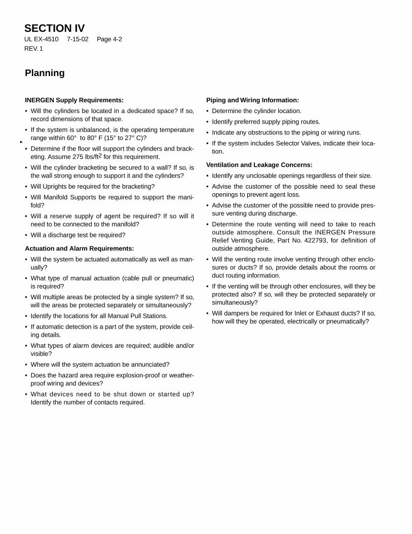
SECTION IVUL EX-4510 7-15-02 Page 4-2
REV. 1
Planning
INERGEN Supply Requirements:
• Will the cylinders be located in a dedicated space? If so,record dimensions of that space.
• If the system is unbalanced, is the operating temperaturerange within 60° to 80° F (15° to 27° C)?
• Determine if the floor will support the cylinders and brack-eting. Assume 275 lbs/ft2 for this requirement.
• Will the cylinder bracketing be secured to a wall? If so, isthe wall strong enough to support it and the cylinders?
• Will Uprights be required for the bracketing?
• Will Manifold Supports be required to support the mani-fold?
• Will a reserve supply of agent be required? If so will itneed to be connected to the manifold?
• Will a discharge test be required?
Actuation and Alarm Requirements:
• Will the system be actuated automatically as well as man-ually?
• What type of manual actuation (cable pull or pneumatic)is required?
• Will multiple areas be protected by a single system? If so,will the areas be protected separately or simultaneously?
• Identify the locations for all Manual Pull Stations.
• If automatic detection is a part of the system, provide ceil-ing details.
• What types of alarm devices are required; audible and/orvisible?
• Where will the system actuation be annunciated?
• Does the hazard area require explosion-proof or weather-proof wiring and devices?
• What devices need to be shut down or started up?Identify the number of contacts required.
Piping and Wiring Information:
• Determine the cylinder location.
• Identify preferred supply piping routes.
• Indicate any obstructions to the piping or wiring runs.
• If the system includes Selector Valves, indicate their loca-tion.
Ventilation and Leakage Concerns:
• Identify any unclosable openings regardless of their size.
• Advise the customer of the possible need to seal theseopenings to prevent agent loss.
• Advise the customer of the possible need to provide pres-sure venting during discharge.
• Determine the route venting will need to take to reachoutside atmosphere. Consult the INERGEN PressureRelief Venting Guide, Part No. 422793, for definition ofoutside atmosphere.
• Will the venting route involve venting through other enclo-sures or ducts? If so, provide details about the rooms orduct routing information.
• If the venting will be through other enclosures, will they beprotected also? If so, will they be protected separately orsimultaneously?
• Will dampers be required for Inlet or Exhaust ducts? If so,how will they be operated, electrically or pneumatically?

SECTION VUL EX-4510 12-1-01 Page 5-1
After completing the hazard analysis sub-section in SectionIV Planning, proceed with the following elements to work upa complete design and bill of materials. An example isincluded with each step to help the reader to understandthe procedure. The example uses a computer room andsubfloor as shown below.
APPLICATION METHOD
Total flooding is the only approved application method forINERGEN systems. INERGEN agent is stored and dis-charged as a gas; it does not create a liquid stream, there-fore, local application of INERGEN agent is not possiblebecause the flow of gas cannot be accurately predictedonce it exits the nozzles.
FIGURE 1002203
Total Flooding
The following steps must be followed, in the order they arepresented, to properly design an INERGEN total floodingsystem. A simple design example will be used throughoutthe steps to help understand each step. Use the DesignCalculations Worksheet on Page 5-17 in this section.
STEP NO. 1 – Determine hazard volume(s)
The first step in the design of an INERGEN system is tocalculate the volume of each area to be protected. Multiplythe length times the width to determine the area, and thenmultiply the area times the height to determine the volumefor each hazard area. If any area is an odd shape, thedesigner may need to divide it up into regular shapes thatwill allow volume calculations, and then total all of the vol-umes together to determine the actual volume of that area.
If the irregular shape will affect distribution of agent, it maybe best to calculate sections of the hazard as separateareas and include nozzles for each of these areas.
If the ceiling height exceeds the maximum allowable ceilingheight as defined in the General Information Section of thismanual, multiple levels of nozzles must be designed intothe system. In this case, it is usually beneficial to treat eachlevel as a separate protected area so that proper agent dis-tribution is achieved.
Complete this step for each area protected by the system.
Example:
• Computer Room• 20 ft. 0 in. L x 13 ft. 0 in. W = 260 ft2, x 10 ft. 0 in. H =
2,600 ft3
• Subfloor• 20 ft. 0 in. L x 13 ft. 0 in. W = 260 ft2, x 1 ft. 0 in. H =
260 ft3
STEP NO. 2 – Determine volume of solid, permanentstructures, or equipment
The volume of solid objects in each hazard area that arenot removable can be deducted from the volume of the haz-ard. This volume may include columns, beams, cut-outroom sections, closets that will always be closed, ducts thatpass completely through the area without any openings,and any other large, permanently fixed objects that cannotbe removed from the hazard enclosure.
Calculate the volume of all such objects and add themtogether to determine the amount of space to be deductedfrom the volume.
Complete this step for each enclosure protected by the sys-tem.
Example
Computer Room:• Columns: 2 ft. 6 in. L x 2 ft. 0 in. W = 5 ft2, x 10 ft. 0 in.
H = 50 ft3 x 2 Columns = 100 ft3
Subfloor:• Columns: 2 ft. 6 in. L x 2 ft. 0 in. W = 5 ft2, x 1 ft. 0 in. H
= 5 ft3 x 2 Columns = 10 ft3
Design
ANSUL®
®

Class A Surface Fuels 34.2%
Class B Fuels Heptane 40.7%*
Class C Fuels 34.2%
APPLICATION METHOD (Continued)
Total Flooding (Continued)
STEP NO. 3 – Calculate Reduced Volume
Subtract the volume of solid, permanent objects (Step No.2) from each of the hazard’s volumes (Step No. 1). Theresult is considered to be the Reduced Volume for theenclosure.
Volume – Solid Object Volume = Reduced Volume
Complete this step for each area protected by the system.
Example
Computer Room:• 2,600 ft3 – 100 ft3 = 2,500 ft3
Subfloor:• 260 ft3 – 10 ft3 = 250 ft3
STEP NO. 4 – Determine minimum design concentra-tion
Minimum Design Concentration is defined by NFPA 2001as the Extinguishing Concentration plus a safety factor,depending on the fuel. Extinguishing Concentration is theagent concentration required to extinguish a test fire.
The Minimum Design Concentration for various fuels isshown in the following table:
INERGEN Minimum Design Concentrations
* Contact Ansul Technical Services Depar tment for Minimum DesignConcentrations for other Class B fuels.
Class A, B (contact Ansul for types), and C hazards are ULlisted for INERGEN systems.
Complete this step for each area protected by the system.
Design Concentrations are determined by NFPA 2001,2000 edition, Paragraph 3-4.2 and UL-2127, first edition,Paragraph 59.2(b):
INERGEN cupburner value is 31% for commercial gradeHeptane
Nozzle distribution test concentration = 31.25%
Calculations:
Cupburner or fire test concentration x nozzle efficiencyfactor x safety factor
Nozzle efficiency factor = 31.25 = 1.008____31.0
Safety Factor: Class A = 1.2Class B = 1.3Class C = Class A
For Class A (determine by fire test) – 28.24% x 1.008 x1.2 = 34.2%For Class B (commercial grade heptane) – 31.25% x 1.3= 40.7%For Class B (other Class B fuels) – cupburner x 1.008 x1.3 = design concentrationFor Class C = Class A
For systems with only manual actuation – cupburner orfire test concentration x 1.008 x 1.3 = design concentra-tion
STEP NO. 5 – Determine minimum quantity ofINERGEN agent required
This step is used to determine the minimum amount ofINERGEN agent required to protect each hazard area. Theamount of agent calculated during this step is the minimumamount of agent that is required to protect the hazard area.The amount of agent in the system must always be at leastthis much and may be exceeded. Failure to supply at leastthe amount of agent indicated in this step may prevent thesystem from suppressing a fire.
To determine the minimum quantity of INERGEN agentrequired, determine the lowest anticipated ambient temper-ature for the area being protected and determine thedesign concentration required for the material to be extin-guished. Minimum Ambient Temperature is defined as thelowest anticipated temperature in the enclosure during nor-mal conditions and is usually determined by the environ-mental conditions or the air handling system. This temper-ature is used in the design because it is the “worst case,”meaning that it will require the highest amount of agent.
SECTION VUL EX-4510 7-15-02 Page 5-2
REV. 1
Design

SECTION VUL EX-4510 12-1-01 Page 5-3
Design
APPLICATION METHOD (Continued)
Total Flooding (Continued)
Using these two variables, the INERGEN agent floodingfactor can be calculated in either of two ways:
First: The formula in NFPA 2001 can be used.
X = 2.303 [ VS ] Log10 [ 100 ]S 100-C
X = INERGEN agent flooding factor
S = 9.8579 + 0.02143 (T)
T = minimum anticipated temperature in the protectedvolume (°F)
C = INERGEN concentration, % by volume
VS = Specific volume at 70 °F (cu.ft./lb.) = 11.358 cu.ft./lb.
NOTE: This calculation includes an allowance for the nor-mal leakage (efflux) from a “tight” enclosure due to agentexpansion.
The second option for calculating the required quantity ofINERGEN agent is to refer to the “Flooding Factor Chart” onPage 5-18 in to determine the correct flooding factor to use.To do this, star t by locating the Minimum AmbientTemperature in the left column, follow this line across untilyou reach the column for the Minimum DesignConcentration needed for the design. The number listedwhere the temperature line and the concentration columnmeet is the Flooding Factor to be used. NOTE: If the mini-mum temperature, the minimum design concentration, orboth are not listed, interpolation will be required.
Next, to determine the quantity of INERGEN agent, multiplythe Reduced Hazard Volume by the Flooding Factor deter-mined from the table.
Complete this step for each area protected by the system.
NOTICEThe actual design concentration ofINERGEN agent cannot be less than theconcentration selected in Step No. 4.
Example
Minimum Ambient Temperature = 60 °F.
Flooding Factor = 0.427
Computer Room• 2,500 ft3 x 0.427 = 1067.5 ft3 INERGEN Agent Required
Subfloor• 250 ft3 x 0.427 = 106.8 ft3 INERGEN Agent Required
Step No. 6 – Adjust Quantity of Agent with AltitudeCorrection Factor
It may be necessary at this point to adjust the required ini-tial INERGEN agent quantity for altitude effects. Anincrease in altitude or pressure causes a gas to expand andoccupy more space, which will lead to a higher concentra-tion if the agent quantity is not reduced accordingly. Adecrease in altitude will cause the opposite effect, increas-ing the quantity of agent required. This same effect willapply to increases or decreases in the ambient pressure ascould be caused by ventilation systems designed to main-tain a positive or negative pressure within the enclosure. Toapply the proper adjustment, first look up the altitude orpressure of the hazard on the “Atmospheric CorrectionFactors Chart” on Page 5-20 in this section.
Determine the total INERGEN agent required by multiplyingthe initial INERGEN quantity by the Altitude CorrectionFactor. If the altitude is between 3000 ft. below seal leveland 3000 ft. above sea level, use of the altitude correctionfactor is optional. Interpolation of the table may be neces-sary if the actual altitude or pressure is not listed.
Example
The hazard altitude is 4000 feet. Referring to the chart onPage 5-20, the altitude correction factor of 4000 ft. is 0.86.
Computer Room• 1067.5 ft3 INERGEN Agent x 0.86 = 918.1 ft3 Required
Agent
Subfloor• 106.8 ft3 INERGEN Agent x 0.86 = 91.8 ft3 Required
Agent
STEP NO. 7 – Determine the total system INERGENagent quantity required
Add quantities from all areas to determine the minimumtotal agent quantity required for the entire system.
Example
918.1 ft3 + 91.8 ft3 = 1009.9 ft3 Total Agent Required
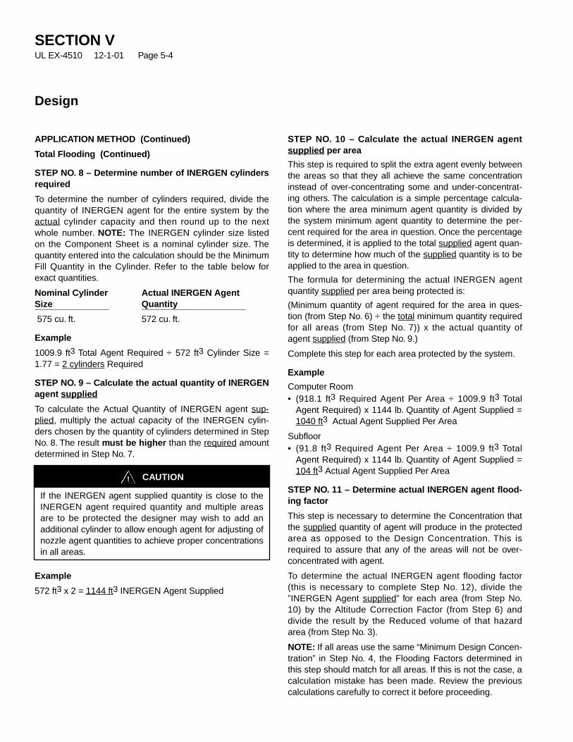
CAUTION!
If the INERGEN agent supplied quantity is close to theINERGEN agent required quantity and multiple areasare to be protected the designer may wish to add anadditional cylinder to allow enough agent for adjusting ofnozzle agent quantities to achieve proper concentrationsin all areas.
APPLICATION METHOD (Continued)
Total Flooding (Continued)
STEP NO. 8 – Determine number of INERGEN cylindersrequired
To determine the number of cylinders required, divide thequantity of INERGEN agent for the entire system by theactual cylinder capacity and then round up to the nextwhole number. NOTE: The INERGEN cylinder size listedon the Component Sheet is a nominal cylinder size. Thequantity entered into the calculation should be the MinimumFill Quantity in the Cylinder. Refer to the table below forexact quantities.
Nominal Cylinder Actual INERGEN AgentSize Quantity_______________ _____________________575 cu. ft. 572 cu. ft.
Example
1009.9 ft3 Total Agent Required ÷ 572 ft3 Cylinder Size =1.77 = 2 cylinders Required
STEP NO. 9 – Calculate the actual quantity of INERGENagent supplied
To calculate the Actual Quantity of INERGEN agent sup-plied, multiply the actual capacity of the INERGEN cylin-ders chosen by the quantity of cylinders determined in StepNo. 8. The result must be higher than the required amountdetermined in Step No. 7.
Example
572 ft3 x 2 = 1144 ft3 INERGEN Agent Supplied
STEP NO. 10 – Calculate the actual INERGEN agentsupplied per area
This step is required to split the extra agent evenly betweenthe areas so that they all achieve the same concentrationinstead of over-concentrating some and under-concentrat-ing others. The calculation is a simple percentage calcula-tion where the area minimum agent quantity is divided bythe system minimum agent quantity to determine the per-cent required for the area in question. Once the percentageis determined, it is applied to the total supplied agent quan-tity to determine how much of the supplied quantity is to beapplied to the area in question.
The formula for determining the actual INERGEN agentquantity supplied per area being protected is:
(Minimum quantity of agent required for the area in ques-tion (from Step No. 6) ÷ the total minimum quantity requiredfor all areas (from Step No. 7)) x the actual quantity ofagent supplied (from Step No. 9.)
Complete this step for each area protected by the system.
Example
Computer Room• (918.1 ft3 Required Agent Per Area ÷ 1009.9 ft3 Total
Agent Required) x 1144 lb. Quantity of Agent Supplied =1040 ft3 Actual Agent Supplied Per Area
Subfloor• (91.8 ft3 Required Agent Per Area ÷ 1009.9 ft3 Total
Agent Required) x 1144 lb. Quantity of Agent Supplied =104 ft3 Actual Agent Supplied Per Area
STEP NO. 11 – Determine actual INERGEN agent flood-ing factor
This step is necessary to determine the Concentration thatthe supplied quantity of agent will produce in the protectedarea as opposed to the Design Concentration. This isrequired to assure that any of the areas will not be over-concentrated with agent.
To determine the actual INERGEN agent flooding factor(this is necessary to complete Step No. 12), divide the”INERGEN Agent supplied” for each area (from Step No.10) by the Altitude Correction Factor (from Step 6) anddivide the result by the Reduced volume of that hazardarea (from Step No. 3).
NOTE: If all areas use the same “Minimum Design Concen-tration” in Step No. 4, the Flooding Factors determined inthis step should match for all areas. If this is not the case, acalculation mistake has been made. Review the previouscalculations carefully to correct it before proceeding.
SECTION VUL EX-4510 12-1-01 Page 5-4
Design
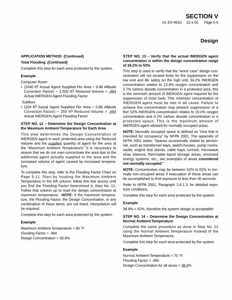
SECTION VUL EX-4510 12-1-01 Page 5-5
Design
APPLICATION METHOD (Continued)
Total Flooding (Continued)
Complete this step for each area protected by the system.
Example
Computer Room• (1040 ft3 Actual Agent Supplied Per Area ÷ 0.86 Altitude
Correction Factor) ÷ 2,500 ft3 Reduced Volume = .484Actual INERGEN Agent Flooding Factor
Subfloor• (104 ft3 Actual Agent Supplied Per Area ÷ 0.86 Altitude
Correction Factor) ÷ 250 ft3 Reduced Volume = .484Actual INERGEN Agent Flooding Factor
STEP NO. 12 – Determine the Design Concentration atthe Maximum Ambient Temperature for Each Area
This step determines the Design Concentration ofINERGEN agent in each protected area using the ReducedVolume and the supplied quantity of agent for the area atthe “Maximum Ambient Temperature.” It is necessary toassure that we do not over-concentrate the area due to theadditional agent actually supplied to the area and theincreased volume of agent caused by increased tempera-ture.
To complete this step, refer to the Flooding Factor Chart onPage 5-11. Star t by locating the Maximum AmbientTemperature in the left column; follow this line across untilyou find the Flooding Factor determined in Step No. 11.Follow that column up to read the design concentration atmaximum temperature. NOTE: If the maximum tempera-ture, the Flooding Factor, the Design Concentration, or anycombination of these items, are not listed, interpolation willbe required.
Complete this step for each area protected by the system.
Example
Maximum Ambient Temperature = 80 °FFlooding Factor = .484Design Concentration = 38.9%
STEP NO. 13 – Verify that the actual INERGEN agentconcentration is within the design concentration rangeof 34.2% to 52%
This step is used to verify that the “worst case” design con-centration will not exceed limits for fire suppression on thelow end and life safety on the high end. 34.2% INERGENconcentration relates to 13.8% oxygen concentration and2.7% carbon dioxide concentration in a protected area, thisis the minimum amount of INERGEN agent required for firesuppression of most fuels. This minimum concentration ofINERGEN agent must be met in all cases. Failure toachieve this concentration may prevent suppression of afire! 52% INERGEN concentration relates to 10.0% oxygenconcentration and 4.2% carbon dioxide concentration in aprotected space. This is the maximum amount ofINERGEN agent allowed for normally occupied areas.
NOTE: Normally occupied space is defined as “One that isintended for occupancy” by NFPA 2001. The appendix ofNFPA 2001 states ”Spaces occasionally visited by person-nel, such as transformer bays, switch-houses, pump rooms,vaults, engine test stands, cable trays, tunnels, microwaverelay stations, flammable liquid storage areas, enclosedenergy systems, etc., are examples of areas considerednot normally occupied.”
NOTE: Concentration may be between 52% to 62% in nor-mally non-occupied areas if evacuation of these areas canbe accomplished to limit exposure to less than 30 seconds.
Refer to NFPA 2001, Paragraph 1-6.1.3, for detailed expo-sure conditions.
Complete this step for each area protected by the system.
Example
38.9% < 52%, therefore the system design is acceptable!
STEP NO. 14 – Determine the Design Concentration atNormal Ambient Temperature
Complete the same procedure as done in Step No. 12using the Normal Ambient Temperature instead of theMaximum Ambient Temperature.
Complete this step for each area protected by the system.
Example
Normal Ambient Temperature = 70 °F.Flooding Factor = .484Design Concentration for all areas = 38.4%
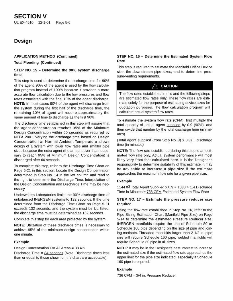
CAUTION!
The flow rates established in this and the following stepsare estimated flow rates only. These flow rates are esti-mate solely for the purpose of estimating device sizes forquotation purposes. The flow calculation program willcalculate actual system flow rates.
APPLICATION METHOD (Continued)
Total Flooding (Continued)
STEP NO. 15 – Determine the 90% system dischargetime
This step is used to determine the discharge time for 90%of the agent. 90% of the agent is used by the flow calcula-tion program instead of 100% because it provides a moreaccurate flow calculation due to the low pressures and flowrates associated with the final 10% of the agent discharge.NOTE: In most cases 90% of the agent will discharge fromthe system during the first half of the discharge time, theremaining 10% of agent will require approximately thesame amount of time to discharge as the first 90%.
The discharge time established in this step will assure thatthe agent concentration reaches 95% of the MinimumDesign Concentration within 60 seconds as required byNFPA 2001. Varying the discharge time based on DesignConcentration at Normal Ambient Temperature allowsdesign of a system with lower flow rates and smaller pipesizes because the extra agent (the amount over that neces-sary to reach 95% of Minimum Design Concentration) isdischarged after 60 seconds.
To complete this step, refer to the Discharge Time Chart onPage 5-21 in this section. Locate the Design Concentrationdetermined in Step No. 14 in the left column and read tothe right to determine the Discharge Time. Interpolation ofthe Design Concentration and Discharge Time may be nec-essary.
Underwriters Laboratories limits the 90% discharge time ofunbalanced INERGEN systems to 132 seconds. If the timedetermined from the Discharge Time Chart on Page 5-21exceeds 132 seconds, and the system must be UL listed,the discharge time must be determined as 132 seconds.
Complete this step for each area protected by the system.
NOTE: Utilization of these discharge times is necessary toachieve 95% of the minimum design concentration withinone minute.
Example
Design Concentration For All Areas = 38.4%Discharge Time = 84 seconds (Note: Discharge times lessthan or equal to those shown on the chart are acceptable)
STEP NO. 16 – Determine the Estimated System FlowRate
This step is required to estimate the Manifold Orifice Devicesize, the downstream pipe sizes, and to determine pres-sure-venting requirements.
To estimate the system flow rate (CFM), first multiply thetotal quantity of actual agent supplied by 0.9 (90%), andthen divide that number by the total discharge time (in min-utes).
(Total agent supplied (from Step No. 9) x 0.9) ÷ dischargetime (in minutes)
NOTE: The flow rate established during this step is an esti-mated flow rate only. Actual system performance will mostlikely vary from that calculated here. It is the Designer’sresponsibility to determine suitability of this estimate. It maybe advisable to increase a pipe size if the estimateapproaches the maximum flow rate for a given pipe size.
Example
1144 ft3 Total Agent Supplied x 0.9 = 1030 ÷ 1.4 DischargeTime in Minutes = 736 CFM Estimated System Flow Rate
STEP NO. 17 – Estimate the pressure reducer sizerequired
Using the flow rate established in Step No. 16, refer to thePipe Sizing Estimation Chart (Manifold Pipe Size) on Page5-14 to determine the estimated Pressure Reducer size.INERGEN manifolds require the use of Schedule 80 orSchedule 160 pipe depending on the size of pipe and join-ing methods. Threaded manifolds larger than 2 1/2 in. pipesize will require Schedule 160 pipe, welded manifolds willrequire Schedule 80 pipe in all sizes.
NOTE: It may be in the Designer’s best interest to increasethe estimated size if the estimated flow rate approaches theupper limit for the pipe size indicated, especially if Schedule160 pipe is required.
Example
736 CFM = 3/4 in. Pressure Reducer
SECTION VUL EX-4510 12-1-01 Page 5-6
Design
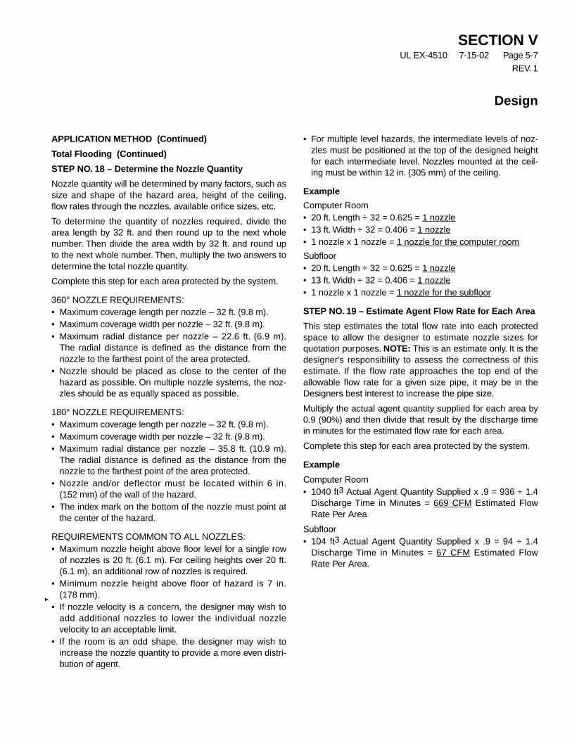
SECTION VUL EX-4510 7-15-02 Page 5-7
REV. 1
Design
APPLICATION METHOD (Continued)
Total Flooding (Continued)
STEP NO. 18 – Determine the Nozzle Quantity
Nozzle quantity will be determined by many factors, such assize and shape of the hazard area, height of the ceiling,flow rates through the nozzles, available orifice sizes, etc.
To determine the quantity of nozzles required, divide thearea length by 32 ft. and then round up to the next wholenumber. Then divide the area width by 32 ft. and round upto the next whole number. Then, multiply the two answers todetermine the total nozzle quantity.
Complete this step for each area protected by the system.
360° NOZZLE REQUIREMENTS:• Maximum coverage length per nozzle – 32 ft. (9.8 m).• Maximum coverage width per nozzle – 32 ft. (9.8 m).• Maximum radial distance per nozzle – 22.6 ft. (6.9 m).
The radial distance is defined as the distance from thenozzle to the farthest point of the area protected.
• Nozzle should be placed as close to the center of thehazard as possible. On multiple nozzle systems, the noz-zles should be as equally spaced as possible.
180° NOZZLE REQUIREMENTS:• Maximum coverage length per nozzle – 32 ft. (9.8 m).• Maximum coverage width per nozzle – 32 ft. (9.8 m).• Maximum radial distance per nozzle – 35.8 ft. (10.9 m).
The radial distance is defined as the distance from thenozzle to the farthest point of the area protected.
• Nozzle and/or deflector must be located within 6 in.(152 mm) of the wall of the hazard.
• The index mark on the bottom of the nozzle must point atthe center of the hazard.
REQUIREMENTS COMMON TO ALL NOZZLES:• Maximum nozzle height above floor level for a single row
of nozzles is 20 ft. (6.1 m). For ceiling heights over 20 ft.(6.1 m), an additional row of nozzles is required.
• Minimum nozzle height above floor of hazard is 7 in.(178 mm).
• If nozzle velocity is a concern, the designer may wish toadd additional nozzles to lower the individual nozzlevelocity to an acceptable limit.
• If the room is an odd shape, the designer may wish toincrease the nozzle quantity to provide a more even distri-bution of agent.
• For multiple level hazards, the intermediate levels of noz-zles must be positioned at the top of the designed heightfor each intermediate level. Nozzles mounted at the ceil-ing must be within 12 in. (305 mm) of the ceiling.
Example
Computer Room• 20 ft. Length ÷ 32 = 0.625 = 1 nozzle• 13 ft. Width ÷ 32 = 0.406 = 1 nozzle• 1 nozzle x 1 nozzle = 1 nozzle for the computer room
Subfloor• 20 ft. Length ÷ 32 = 0.625 = 1 nozzle• 13 ft. Width ÷ 32 = 0.406 = 1 nozzle• 1 nozzle x 1 nozzle = 1 nozzle for the subfloor
STEP NO. 19 – Estimate Agent Flow Rate for Each Area
This step estimates the total flow rate into each protectedspace to allow the designer to estimate nozzle sizes forquotation purposes. NOTE: This is an estimate only. It is thedesigner’s responsibility to assess the correctness of thisestimate. If the flow rate approaches the top end of theallowable flow rate for a given size pipe, it may be in theDesigners best interest to increase the pipe size.
Multiply the actual agent quantity supplied for each area by0.9 (90%) and then divide that result by the discharge timein minutes for the estimated flow rate for each area.
Complete this step for each area protected by the system.
Example
Computer Room• 1040 ft3 Actual Agent Quantity Supplied x .9 = 936 ÷ 1.4
Discharge Time in Minutes = 669 CFM Estimated FlowRate Per Area
Subfloor• 104 ft3 Actual Agent Quantity Supplied x .9 = 94 ÷ 1.4
Discharge Time in Minutes = 67 CFM Estimated FlowRate Per Area.

APPLICATION METHOD (Continued)
Total Flooding (Continued)
STEP NO. 20 – Estimate the Nozzle Flow Rates
If all of the nozzles within the hazard area will have thesame flow rate, divide the Estimated Flow Rate for the Area(Step No. 19) by the nozzle quantity (Step No. 18).
If all of the nozzles within the hazard area will not have thesame flow rate, perform a percentage calculation using thevolume protected by each nozzle divided by the total vol-ume for the area and then multiply the Flow Rate for theArea (Step No. 19) by the volume percent calculated previ-ously to determine the flow rate for that nozzle. Completethis procedure for each nozzle in the system.
If the design includes multiple levels of nozzles, rememberto include all nozzles on all levels in this step.
Complete this step for each area protected by the system.
Example
Computer Room• 669 CFM (Estimated Flow Rate Per Area) ÷ 1 = 669 CFM
Nozzle Flow Rate
Subfloor• 67 CFM (Estimated Flow Rate Per Area ÷ 1 = 67 CFM
Nozzle Flow Rate
STEP NO. 21 – Determine the Nozzle Locations and LayOut the Interconnecting Piping
Using a plan view drawing of the protected areas, locateeach nozzle and the cylinders. NOTE: Nozzles should belocated at the top of the hazard area, aimed downward.Connect the nozzles with piping following the piping guide-lines listed in the General Information Section and theInstallation Section. After all of the nozzles are connected,lay out the piping to the cylinders and lay out the manifold.Manifold layout limitations can be found in the InstallationSection of the Design Manual, including a manifold heightchart.
When laying out the manifold, remember that a center out-let manifold will usually allow the use of smaller pipe sizesfor the horizontal legs of the manifold where the cylindersare connected, especially if these legs are a single size. “H”shaped manifolds are usually preferable to “end outlet,” “L,”or “U” shaped manifolds. Center to center distances for thecylinders will normally be 12 in. due to the spacing of thebrackets. It is normally recommended to keep the PressureReducer as close to the manifold outlet as possible toreduce the amount of Schedule 80 or 160 pipe required inthe system.
When selecting pipe schedules, keep in mind that themanifold pressure should be assumed to be 2,900 PSI.This will usually dictate the use of Schedule 160 pipe forany size larger than 2 1/2 in. pipe if threaded fittings will beused. If welded or “rolled groove” fittings are used in themanifold, Schedule 80 pipe will be acceptable in mostcases for all pipe sizes through 6 in.
If the system is a “Balanced” system, review the pipe layoutto assure that all legs of the piping are equal in regards toflow and fittings and that the maximum length of pipe forthe longest leg from the manifold to the furthest nozzle isnot more than 10% longer than the shortest leg from themanifold to the closest nozzle.
If the system is an “Unbalanced” system, review the pipingarrangement for proper tee splits per the limitations listed inthe General Information Section and revise the pipingaccordingly if necessary.
If the system includes Selector Valves, refer to the informa-tion later in this section for assistance in laying out the pip-ing for the Selector Valve manifold.
STEP 22 – Complete an Isometric Sketch of the PipingLayout
Create an isometric sketch of the piping for use in inputtingthe information in the INERGEN Designer program. Afterthe sketch has been completed, identify all of the pipelengths.
Identify and label all node points, manifold designators, andnozzle designators. The first point on the manifold is con-sidered as the inlet to the cylinder valve inside the cylinder.The second point is considered as the outlet of the dis-charge hose. This first section of pipe must always beincluded in any system; therefore the flow calculation pro-gram will include it automatically.
• Piping Node Points – Piping sections are numberedstarting at the inlet to the valve on the cylinder furthestfrom the manifold outlet. Each point where flow increas-es, direction changes, or flow splits marks the end of apipe section and the start of a new pipe section. Nodesmust be numbered numerically: 1, 2, 3, etc. Sequentialnumbering is not required, however, it is recommended toprevent confusion. NOTE: Anytime a tee is added to thepiping to take off pressure to operate a pressure trip orpressure switch, a node point should be assigned andthe fitting should be entered as a coupling to address thefriction loss.
SECTION VUL EX-4510 12-1-01 Page 5-8
Design

SECTION VUL EX-4510 7-15-02 Page 5-9
REV. 1
Design
APPLICATION METHOD (Continued)
Total Flooding (Continued)
• Nozzles – Nozzles are indicated with a number between301 and 499. Sequential numbering is not required; how-ever, it is recommended that the designer use some sortof numbering system to prevent confusion.
• Manifold Designator – The manifold designator code isa number between 1 and 299. This code identifies thenumber of cylinders supplying any given section of themanifold. Example: A system with 38 cylinders supplyinga section of pipe would, for that point, have a manifolddesignator of 38. Another system, having 102 cylinderssupplying a section of pipe, would, for that point, have amanifold designator of 102.
The first section of pipe chosen as a manifold designatormust start with the designator code of 1.
STEP 23 – Estimate Pipe Size for All Areas (Optional)
To complete this step, start by labeling all nozzle flow rates.Then, working backwards from the nozzles, determine theflow rate for each section of pipe. Using the Pipe SizeEstimation Chart on Page 5-14 of this section, estimate thepipe size for each section of pipe and the nozzles. Considera pipe section as short if it is less than 20 feet in length.Consider a pipe section as long if it exceeds 20 feet inlength; remember that these are estimates only. The design-er may wish to judge the merits of selecting a long run ifthis is necessary. Selection of a long run will increase thepipe size due to increased friction loss encountered in longpipe runs.
Flow rates for individual pipes in the manifold can be esti-mated by dividing the flow rate for the system (Step No. 16)by the number of cylinders in the system. Then multiply theresult by the number of cylinders supplying that section ofpipe.
The flow calculation program will estimate pipe sizes auto-matically; therefore this step is optional. The designer maywish to use the pipe size estimation charts to estimate thenozzle pipe sizes for quotation purposes. NOTE: This is anestimate only. It is the designer’s responsibility to assessthe correctness of this estimate. If the flow rate approachesthe top end of the allowable flow rate for a given size, it maybe in the Designers best interest to increase the pipe size.
Example
Computer Room• 669 CFM = 3/4 in. Nozzle
Subfloor• 67 CFM = 1/4 in. Nozzle
STEP 24 — Determine the Open Area Required forPressure Venting During Discharge
It is necessary to calculate the opening area needed forpressure venting to determine if the hazard area(s) includesufficient openings or if more openings are required.
Refer to the Pressure Relief Venting Guide, Part No.422793, in the Appendix section for detailed information todetermine free vent area required. If the enclosures wallstrength cannot be determined, Ansul recommends a maxi-mum wall strength of 5 lbs./ft2 unless the architect or ownerprovides a different value.
See Page No. 3, Steps No. 1 and No. 3 in The VentingGuide for calculations to determine the Free Vent Arearequired.
Example
Computer Room• (2.7 x 1040 ft3) ÷ 1.4 = 2006 CFM, (2006 x 0.0855) ÷ sq.
rt. of 5 PSF = 76.7 in2 Free Vent Area Required
Subfloor• (2.7 x 104 ft3) ÷ 1.4 = 201 CFM, (201 x 0.0855) ÷ sq. rt. of
5 PSF = 7.7 in2 Free Vent Area Required
STEP NO. 25 – Perform Flow Calculations
With the information developed in Steps No. 21 and 22, runthe computer program to determine the final pipe sizes,nozzle orifice sizes, and pressure reducer size.
If the system protects more than one area by use ofSelector Valves, the flow calculation for the worst systemfrom a hydraulic flow standpoint should be calculated first.Once the pipe sizes for this system are selected, the mani-fold for all of the other systems must use the same sizepipe. These pipe sizes must be entered manually. Pipesizes starting with the outlet from the Selector Valve mani-fold, including the section immediately before the SelectorValve, can be estimated by the flow calculation program.

APPLICATION METHOD (Continued)
Total Flooding (Continued)
STEP NO. 26 – Revise the Design Worksheet (Optional)
This step is to be completed only if the designer is complet-ing the INERGEN Design Worksheet manually; theINERGEN Designer program automatically revises theDesign Worksheet after a flow calculation is completed.
Rework the design worksheet for each area starting withthe entry for “Actual INERGEN Agent Supplied Per Area,Step No. 10,” and ending with “System Discharge Time,Step No. 15.” Replace the “actual INERGEN agent suppliedper area” with the agent quantities determined in the“Nozzle Performance” section of the flow calculation pro-gram.
STEP NO. 27 – Verify Actual System Performance
Once a flow calculation has been completed and theDesign Worksheet has been revised (optional), it is impor-tant that the designer review all results to verify system per-formance. The INERGEN Designer program will flag mosterrors and prevent a completed flow calculation until theyhave been corrected. However, this does not guarantee thatthe systems performance will match what the designerexpects. Careful review is an important step in the design ofany Fire Protection system, which must be completedbefore final approval of the system.
Review the revised worksheet to verify that:
1. The agent concentration at maximum temperature iswithin acceptable limits (34.2% to 52% for occupiedspaces).
2. The agent quantity is above the amount required in theInitial INERGEN Quantity box (see Step No. 7).
3. The discharge time from the flow calculation is equal toor less than that listed for all areas on the DesignWorksheet.
STEP NO. 28 – Determine the Pilot CylinderRequirements
After all flow calculations have been completed, refer to thefollowing table, “Pilot Cylinder Requirements Table”, todetermine if additional pilot cylinders are required in thesystem.
Proper backpressure actuation of the INERGEN cylindervalves requires that the manifold reach a prescribed mini-mum pressure. If this minimum pressure is not achieved inthe manifold, only the cylinder operated by the electric actu-ator will open. This will result in a system discharge whichwill not allow enough agent to the hazard enclosure, whichmay prevent achievement of the proper minimum designconcentration and result in the failure to suppress a fire.The pilot cylinder requirements identified on the “PilotCylinder Requirements Table” allows pressure from theelectric actuator to operate as many pilot cylinders as nec-essary to assure that the manifold reaches a pressure highenough to open all cylinders attached to that manifold.
Example(Estimated Pilot Cylinder Requirement)System Flow Rate = 736 CFM(1) Pilot Cylinder Required
SECTION VUL EX-4510 12-1-01 Page 5-10
Design

INERGEN SYSTEM DESIGN SECONDARYPILOT CYLINDER REQUIREMENT TABLE
EstimatedMaximum Maximum
Pilot Cylinders System Flow Rate Orifice DiameterRequired (cu ft./min.) (inches)
1 5,000 .7502 9,000 1.0633 14,500 1.2974 17,000 1.5005 24,000 1.6726 29,000 1.8287 34,000 1.9848 37,000 2.1099 42,000 2.250
10 46,000 2.37511 51,000 2.50012 53,000 2.59413 57,000 2.70314 59,000 2.79715 61,000 2.906
STEP NO. 29 – Complete Layout of the SystemAt this point, all final details of the system can be finalized.These details include: design of the Pilot Cylinder Actuationsystem, bracketing, actuation components, etc.
STEP NO. 30 – Create a Bill of MaterialsCreate a list of all materials necessary to install the system.This can be done by hand or by use of the Bill of MaterialsTab in the INERGEN Designer program.
STEP NO. 31 – Create Installation DrawingsThe final step in the design of an INERGEN system is com-pletion of installation drawings for submittal to the appropri-ate authority and the customer. These drawings shouldinclude all details necessary for installation of this system.
SELECTOR VALVE SYSTEMSThe following information must be considered when design-ing a selector valve system.
• Each hazard area must be treated as a separate systemdesign.
• Start with the largest system (system with the highestestimated flow rate). This is necessary so that the mani-fold size will handle the maximum quantity of INERGEN.
• After calculating the largest system first, complete addi-tional system calculations on the remaining systems. Usethe manifold pipe size calculated from first system design(system with the highest flow rate).
• Selector valve systems can be used for multi-hazardswhen all areas are considered separate fire hazards.
• Selector valve can be located either upstream or down-stream of the pressure reducer.
• The piping located between the pressure reducer and theselector valve must be rated for pressure of 2900 psi (200bar) or greater.
• Maximum distance between selector valve and pressurereducer is 20 ft. (6.1 m).
• When designing the manifold for a selector valve system,check valves must be installed in the manifold to separatethe actuation of the smaller system(s) from the larger ones.
• A minimum of 10 pipe diameters is required between thepressure reducer and the selector valve. The pressurereducer can be located either before or after the selectorvalve.
• If the pressure reducer is downstream of a selector valve,each pressure reducer must utilize its own individualselector valve.
The following are four typical examples of selector valvesystems:
002714
ADAPTOR PARTNO. 873236 (TYP.) MALE ELBOW
PART NO. 832334(TYP.)
TEE, PART NO.418359 (TYP.)
SECONDARYPILOT VALVE(S)
PILOTVALVE
16 IN. STAINLESSSTEEL HOSEPART NO. 831809 (TYP.)
SECTION VUL EX-4510 7-15-02 Page 5-11
REV. 1
Design

HEADERVENT
HEADERVENT
CHECKVALVES
HEADERVENT
5 CYL.SELECTORVALVE
4 CYL.SELECTORVALVE
2 CYL.SELECTORVALVE
ELECTRIC ACTUATOR (TYP.)
002204
CONTROLPANEL
CONTROLPANEL
CHECKVALVE
CHECKVALVE
CHECKVALVE
HEADERVENT
PILOT 2 CYL.SYSTEM
5 CYL.SELECTORVALVE
4 CYL.SELECTORVALVE
2 CYL.SELECTORVALVE
ELECTRIC ACTUATOR (TYP.)
PILOT 4 CYL.SYSTEM
HEADER VENT (TYP.)
PILOT 5 CYL.SYSTEM
2 CYL. SYSTEM
4 CYL. SYSTEM
5 CYL. SYSTEM
EXAMPLE NO. 1 (TYPICAL SELECTOR VALVE INSTALLATION – ELECTRIC ACTUATION)
EXAMPLE NO. 2 (TYPICAL SELECTOR VALVE INSTALLATION – ELECTRIC ACTUATION)
PRESSURE REDUCER (TYP.)
NOTE: PRESSURE REDUCER CANBE LOCATED EITHERUPSTREAM OR DOWN-STREAM OF THESELECTOR VALVE.
PRESSURE REDUCER (TYP.)
NOTE: PRESSURE REDUCER CAN BELOCATED EITHER UPSTREAMOR DOWNSTREAM OF THESELECTOR VALVE.
AA
A A A
A
PILOT5 CYL.SYSTEM
PILOT4 CYL.SYSTEM
PILOT2 CYL.SYSTEM
002205
SECTION VUL EX-4510 12-1-01 Page 5-12
Design

EXAMPLE NO. 3 (TYPICAL SELECTOR VALVE INSTALLATION – MANUAL ACTUATION)
EXAMPLE NO. 4 (TYPICAL SELECTOR VALVE INSTALLATION –MANUAL ACTUATION WITH CONNECTED RESERVE)
LEVERRELEASE
LEVERRELEASE
MANUALCONTROL BOX
SYSTEMNO. 1PILOT
SELECTORVALVE #2
SELECTORVALVE #1
CHECKVALVE
LEVERRELEASE
MANUALCONTROL BOX
LEVERRELEASE
CHECKVALVE
SYSTEMNO. 2PILOT
MANUALPULL STATION
MANUALCONTROL BOX
PULLEY ELBOWS(REQUIRED AT EACHCHANGE IN DIRECTION)
MANUALPULL STATION
SV #2 SV #1
PRESSURE REDUCER (TYP.)
NOTE: PRESSURE REDUCERCAN BE LOCATEDEITHER UPSTREAM ORDOWNSTREAM OF THESELECTOR VALVE.
PRESSURE REDUCER (TYP.)
NOTE: PRESSURE REDUCER CAN BELOCATED EITHER UPSTREAMOR DOWNSTREAM OF THESELECTOR VALVE.
MANUALCONTROL BOX
MANUALCONTROL BOX
MANUALCONTROL BOX
MANUALCONTROL BOX MANUAL
CONTROL BOX
MANUALPULL STATION
MANUAL CONTROL BOX MANUAL CONTROL BOX
PULLEY ELBOW (REQUIRED ATEACH CHANGE IN DIRECTION)
M M
SV #2 SV #1R R
MP
MP
MP
MP
002206
002207
SECTION VUL EX-4510 12-1-01 Page 5-13
Design

SAMPLE APPLICATIONS
Refer to Section XI (Typical Applications) for examples ofsome typical applications. By reviewing these examples, itmay help answer some questions concerning the totaldesign process.
ACTUATION REQUIREMENTS
Three types of actuation are available for the INERGENsystem: manual, pneumatic, and electric.
Manual Actuation
Manual actuation can be used with or without automaticdetection. When no detection is required, based on accep-tance by the authority having jurisdiction, the lever actuatorcan be mounted on top of the INERGEN cylinder valve. Themanual lever release actuator provides a manual means ofagent cylinder actuation by direct manual actuation of itspull lever or cable actuation when used in conjunction witha remote manual pull station. One pilot cylinder valve isrequired on multiple cylinder systems. The pilot valve is theonly one that requires a manual actuator. On two or morecylinder systems, the remaining cylinders are actuated bythe pressure generated within the distribution manifold. Themaximum length of actuator cable which may be used inthe remote line is 125 ft. (38 m). The maximum number ofcorner pulley elbows is 10.
Pneumatic Actuation
Pneumatic actuation is accomplished by supplying pres-sure to the pilot port on the INERGEN cylinder valve. Thepressure is supplied from an LT-30-R nitrogen cartridgelocated in the ANSUL AUTOMAN II-C release. The car-tridge pressure pneumatically opens the cylinder valve.
One pilot valve is required in single or multiple cylinder sys-tems. The rest of the cylinders will be actuated from thepressure of the pilot cylinder. The maximum length of 1/4 in.Schedule 40 pipe is 100 ft. (30.5 m). If it is necessary tohave an actuation pipe run which exceeds the maximumallowable 1/4 in. pipe requirements, 1/4 in. O.D. stainlesssteel tubing with a wall thickness of 0.065 can be used forthe actuation line. When this size tubing is used, a maxi-mum of 300 ft. (91.4 m), with no reductions for elbows ortees, is allowed. See NFPA 2001, Paragraph2-3.4.2 for information on pneumatic control equipment
Electric Actuation
CV-98 Valve – One or two HF electric actuators, Part No.73327, can be used on a single release circuit. When usingonly one electric actuator, an in-line resistor, Part No.73606, must always be used.
Normal system design requires that only one pilot valvecontains an electric actuator. On multiple cylinder systems,the additional cylinders are actuated by the pressure gener-ated within the distribution manifold.
In auxiliary or override applications, a lever actuator can beinstalled on top of the CV-98 valve or on top of HF electricactuator.
Multiple Manifold Actuator
A maximum of 40 cylinders can be installed on a singlemanifold and actuated from a single actuated main pilotvalve. When more than 40 cylinders are required, up to 12additional pilot valves (12 additional manifolds each havinga maximum of 40 cylinders) can be pneumatically actuatedfrom the “pilot” manifold. See Installation Section VI fordetailed piping requirements.
“Secondary” Pilot Cylinders
On some very large systems, because of the manifold size,“secondary” pilot valves are required to be actuated fromthe single “main” pilot valve in order to produce enoughmanifold pressure to operate the remaining cylinders on themanifold. See “Pilot Cylinder Requirement Table” in StepNo. 28, Page 5-10, for detailed secondary pilot cylinderinformation.
SECTION VUL EX-4510 12-1-01 Page 5-14
Design
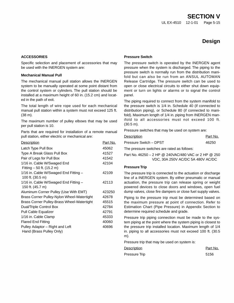
SECTION VUL EX-4510 12-1-01 Page 5-15
Design
ACCESSORIES
Specific selection and placement of accessories that maybe used with the INERGEN system are:
Mechanical Manual Pull
The mechanical manual pull station allows the INERGENsystem to be manually operated at some point distant fromthe control system or cylinders. The pull station should beinstalled at a maximum height of 60 in. (15.2 cm) and locat-ed in the path of exit.
The total length of wire rope used for each mechanicalmanual pull station within a system must not exceed 125 ft.(38 m).
The maximum number of pulley elbows that may be usedper pull station is 10.
Parts that are required for installation of a remote manualpull station, either electric or mechanical are:
Description Part No.
Latch Type Pull Box 45062Type A Break Glass Pull Box 41527Pair of Legs for Pull Box 415421/16 in. Cable W/Swaged End 42104Fitting – 50 ft. (15.2 m)1/16 in. Cable W/Swaged End Fitting – 42109100 ft. (30.5 m)1/16 in. Cable W/Swaged End Fitting – 42113150 ft. (45.7 m)Aluminum Corner Pulley (Use With EMT) 423250Brass Corner Pulley-Nylon Wheel-Watertight 42678Brass Corner Pulley-Brass Wheel-Watertight 45515Dual/Triple Control Box 42784Pull Cable Equalizer 427911/16 in. Cable Clamp 45333Flared End Fitting 40060Pulley Adaptor – Right and Left 40696Hand (Brass Pulley Only)
Pressure Switch
The pressure switch is operated by the INERGEN agentpressure when the system is discharged. The piping to thepressure switch is normally run from the distribution mani-fold but can also be run from an ANSUL AUTOMANRelease Cartridge. The pressure switch can be used toopen or close electrical circuits to either shut down equip-ment or turn on lights or alarms or to signal the controlpanel.
The piping required to connect from the system manifold tothe pressure switch is 1/4 in. Schedule 40 (if connected todistribution piping), or Schedule 80 (if connected to mani-fold). Maximum length of 1/4 in. piping from INERGEN man-ifold to all accessories must not exceed 100 ft.(30.5 m).
Pressure switches that may be used on system are:
Description Part No.
Pressure Switch – DPST 46250
The pressure switches are rated as follows:
Part No. 46250 – 2 HP @ 240VAC/480 VAC or 2 HP @ 250VDC, 30A 250V AC/DC 5A 480V AC/DC
Pressure Trip
The pressure trip is connected to the actuation or dischargeline of a INERGEN system. By either pneumatic or manualactuation, the pressure trip can release spring or weightpowered devices to close doors and windows, open fueldump valves, close fire dampers or close fuel supply valves.
Piping to the pressure trip must be determined based onthe maximum pressure at point of connection. Refer toEstimation Chart (Pipe Pressure) in Appendix Section todetermine required schedule and grade.
Pressure trip piping connection must be made to the sys-tem piping at the point where the system piping is closest tothe pressure trip installed location. Maximum length of 1/4in. piping to all accessories must not exceed 100 ft. (30.5m).
Pressure trip that may be used on system is:
Description Part No.
Pressure Trip 5156
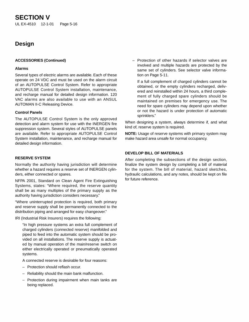
ACCESSORIES (Continued)
Alarms
Several types of electric alarms are available. Each of theseoperate on 24 VDC and must be used on the alarm circuitof an AUTOPULSE Control System. Refer to appropriateAUTOPULSE Control System installation, maintenance,and recharge manual for detailed design information. 120VAC alarms are also available to use with an ANSULAUTOMAN II-C Releasing Device.
Control Panels
The AUTOPULSE Control System is the only approveddetection and alarm system for use with the INERGEN firesuppression system. Several styles of AUTOPULSE panelsare available. Refer to appropriate AUTOPULSE ControlSystem installation, maintenance, and recharge manual fordetailed design information.
RESERVE SYSTEM
Normally the authority having jurisdiction will determinewhether a hazard requires a reserve set of INERGEN cylin-ders, either connected or spares.
NFPA 2001, Standard on Clean Agent Fire ExtinguishingSystems, states: “Where required, the reserve quantityshall be as many multiples of the primary supply as theauthority having jurisdiction considers necessary.”
“Where uninterrupted protection is required, both primaryand reserve supply shall be permanently connected to thedistribution piping and arranged for easy changeover.”
IRI (Industrial Risk Insurers) requires the following:
“In high pressure systems an extra full complement ofcharged cylinders (connected reserve) manifolded andpiped to feed into the automatic system should be pro-vided on all installations. The reserve supply is actuat-ed by manual operation of the main/reserve switch oneither electrically operated or pneumatically operatedsystems.
A connected reserve is desirable for four reasons:
– Protection should reflash occur.
– Reliability should the main bank malfunction.
– Protection during impairment when main tanks arebeing replaced.
– Protection of other hazards if selector valves areinvolved and multiple hazards are protected by thesame set of cylinders. See selector valve informa-tion on Page 5-11.
If a full complement of charged cylinders cannot beobtained, or the empty cylinders recharged, deliv-ered and reinstalled within 24 hours, a third comple-ment of fully charged spare cylinders should bemaintained on premises for emergency use. Theneed for spare cylinders may depend upon whetheror not the hazard is under protection of automaticsprinklers.”
When designing a system, always determine if, and whatkind of, reserve system is required.
NOTE: Usage of reserve systems with primary system maymake hazard area unsafe for normal occupancy.
DEVELOP BILL OF MATERIALS
After completing the subsections of the design section,finalize the system design by completing a bill of materialfor the system. The bill of material, hazard sketches,hydraulic calculations, and any notes, should be kept on filefor future reference.
SECTION VUL EX-4510 12-1-01 Page 5-16
Design

DAT
E:
____
____
____
____
____
____
____
____
____
____
____
____
____
____
____
____
____
____
____
__
QU
OT
E/J
OB
NU
MB
ER
:__
____
____
____
____
____
____
____
____
____
____
____
____
____
____
____
__
CU
STO
ME
R:
____
____
____
____
____
____
____
____
____
____
____
____
____
____
____
____
____
____
VO
LU
ME
CA
LC
UL
AT
ION
S:
AR
EA
1A
RE
A 2
AR
EA
3A
RE
A 4
AR
EA
5A
rea
Nam
e:Le
ngth
(ft.
):W
idth
(ft.
):H
eigh
t (ft.
):
Are
a (s
q.ft.
):V
olum
e (c
u.ft.
):
Volu
me
Red
uct
ion
s:S
truc
tura
l Red
uctio
ns (
cu.f
t.):
Tota
l Red
uced
Vol
ume:
(Vol
ume
– S
truc
tura
l Red
uctio
ns)
RO
OM
MIN
IMU
MA
MB
IEN
TT
EM
P.:
DE
SIG
NC
ON
CE
NT
RA
TIO
N:
FL
OO
DIN
GFA
CTO
R:
(Fro
m T
able
)
INIT
IAL
INE
RG
EN
QU
AN
TIT
YC
AL
C.:
INE
RG
EN
Qua
ntity
(cu
.ft.)
:(T
otal
Red
uced
Vol
ume
x F
lood
ing
Fact
or)
or (
Form
ula
from
Des
ign
Man
ual)
ALT
ITU
DE
CO
RR
EC
TIO
N:
Hei
ght A
bove
or
Bel
ow S
ea L
evel
:Fa
ctor
:(F
rom
Des
ign
Man
ual T
able
)
AC
TU
AL
INE
RG
EN
QU
AN
TIT
Y(c
u.f
t.):
(Ini
tial I
NE
RG
EN
Qua
ntity
x A
ltitu
de C
orre
ctio
n Fa
ctor
)
TOTA
LIN
ER
GE
NQ
TY.
(cu
.ft.
):(S
um o
f all
Act
ual I
NE
RG
EN
qty’
s)
SE
CT
ION
VU
LE
X-4
510
1
2-1-
01
Pag
e 5-
17
INE
RG
EN
®S
YS
TE
MD
ES
IGN
CA
LC
UL
AT
ION
WO
RK
SH
EE
T

TOTA
LIN
ER
GE
NQ
TY.
(CU
.FT.
):(F
rom
Pag
e 1)
CY
LIN
DE
RR
EQ
UIR
EM
EN
TS
:TO
TAL
CY
LIN
DE
RC
APA
CIT
Y:
(Tot
al IN
ER
GE
Nqt
y.÷
Cyl
inde
r C
apac
ity r
ound
ed to
nex
t hig
hest
who
le n
umbe
r)(C
yl.q
ty.x
Cyl
.cap
.)57
2 cu
.ft.
Cyl
inde
rs:
CY
LIN
DE
RS
IZE
SE
LE
CT
ED
:(C
ylin
der
qty.
x C
ylin
der
capa
city
)IN
ER
GE
NA
GE
NT
SU
PP
LIE
D:
AC
TU
AL
INE
RG
EN
AG
EN
TP
ER
AR
EA
:[(
Act
ual I
NE
RG
EN
Qty
.÷To
tal I
NE
RG
EN
Qty
.) x
INE
RG
EN
Age
nt S
uppl
ied]
AC
TU
AL
INE
RG
EN
FL
OO
DIN
G F
AC
TOR
:[(
Act
ual I
NE
RG
EN
Age
nt p
er A
rea
÷A
lt.C
orre
ctio
n Fa
ctor
)÷
Tota
l Red
uced
Vol
ume]
CO
NC
EN
TR
AT
ION
RA
NG
E C
HE
CK
:(D
esig
n C
on
c.M
ust
be
Bet
wee
n 3
4.2%
– 5
2% F
or
Occ
up
ied
Sp
aces
)
Roo
m M
ax.A
mbi
ent T
emp.
:D
esig
n C
once
ntra
tion
at M
ax.T
emp.
:(L
ocat
e A
ctua
l IN
ER
GE
NC
onc.
at M
ax.T
emp.
on T
able
, or
Use
Cal
c.in
Des
ign
Man
ual)
DIS
CH
AR
GE
TIM
E:
Nor
mal
Am
bien
t Tem
pera
ture
:D
esig
n C
once
ntra
tion
at A
mbi
ent T
emp.
:(L
ocat
e A
ctua
l IN
ER
GE
NC
onc.
at A
mbi
ent T
emp.
on T
able
, or
Use
Cal
c.in
Des
ign
Man
ual)
90%
of A
gent
Dis
char
ge T
ime
(Sec
.):
(Tim
e Fr
om T
able
in D
esig
n M
anua
l)90
% o
f Age
nt D
isch
arge
Tim
e (M
in.)
:(D
isch
arge
Tim
e (S
ec.)
÷60
)
ES
TIM
AT
ED
FL
OW
RA
TE
SE
stim
ated
Sys
tem
Flo
w R
ate:
[(IN
ER
GE
NA
gent
Sup
plie
d x
.9)
÷90
% D
isch
arge
Tim
e (M
in.)
]
Est
imat
ed P
ress
ure
Red
uce
r P
ipe
Siz
e:(R
efer
to P
ipe
Siz
ing
Cha
rt)
Noz
zle
Qua
ntity
:[L
engt
h ÷
32 (
Rou
nded
to N
ext H
ighe
st W
hole
Num
ber)
x W
idth
÷32
(R
ound
ed to
Nex
t Hig
hest
Who
le N
umbe
r)]
Est
imat
ed N
ozzl
e F
low
Rat
e:[(
(Act
ual I
NE
RG
EN
Age
nt P
er A
rea
x .9
) ÷
90%
Dis
char
ge T
ime
(Min
.))
÷N
ozzl
e Q
uant
ity]
Est
imat
ed N
ozz
le P
ipe
Siz
e:P
ipe
Leng
th F
acto
r (S
= S
hort
, L =
Lon
g):
Pip
e S
ize:
(Ref
er to
Pip
e S
izin
g C
hart
)
ANSUL and INERGEN are trademarks of Ansul Incorporated or its affiliates.
ANSUL INCORPORATED, ONE STANTON STREET, MARINETTE, WI 54143-2542 715-735-7411 Form No. F-2001293 © 2001 Ansul Incorporated Litho in U.S.A.
INE
RG
EN
®S
YS
TE
MD
ES
IGN
CA
LC
UL
AT
ION
WO
RK
SH
EE
T(C
on
tin
ued
)

FL
OO
DIN
GFA
CTO
RS
FO
RIG
541
(cu
bic
feet
/cu
bic
foo
t)
Spe
cific
Te
mp.
Vol
ume
(°F
)C
u.F
t./lb
.33
%34
%34
.2%
35%
36%
37%
38%
39%
40%
41%
42%
43%
44%
45%
46%
___
____
____
____
____
____
____
____
____
____
____
____
____
____
____
____
____
____
–40
9.00
10.
505
0.52
40.
528
0.54
40.
563
0.58
30.
603
0.62
40.
645
0.66
60.
687
0.70
90.
732
0.75
50.
778
–30
9.21
50.
494
0.51
20.
516
0.53
10.
550
0.57
00.
589
0.60
90.
630
0.65
00.
672
0.69
30.
715
0.73
70.
760
–20
9.42
90.
482
0.50
10.
504
0.51
90.
538
0.55
70.
576
0.59
60.
615
0.63
60.
656
0.67
70.
699
0.72
00.
742
–10
9.64
40.
472
0.48
90.
493
0.50
70.
526
0.54
40.
563
0.58
20.
602
0.62
20.
642
0.66
20.
683
0.70
40.
726
09.
858
0.46
10.
479
0.48
20.
496
0.51
40.
532
0.55
10.
570
0.58
90.
608
0.62
80.
648
0.66
80.
689
0.71
0
1010
.072
0.45
20.
469
0.47
20.
486
0.50
30.
521
0.53
90.
558
0.57
60.
595
0.61
40.
634
0.65
40.
674
0.69
5
2010
.287
0.44
20.
459
0.46
20.
476
0.49
30.
510
0.52
80.
546
0.56
40.
583
0.60
20.
621
0.64
00.
660
0.68
0
3010
.501
0.43
30.
450
0.45
30.
466
0.48
30.
500
0.51
70.
535
0.55
30.
571
0.58
90.
608
0.62
70.
647
0.66
7
4010
.715
0.42
50.
441
0.44
40.
457
0.47
30.
490
0.50
70.
524
0.54
20.
559
0.57
80.
596
0.61
50.
634
0.65
3
5010
.929
0.41
60.
432
0.43
50.
448
0.46
40.
480
0.49
70.
514
0.53
10.
548
0.56
60.
584
0.60
30.
621
0.64
0
6011
.144
0.40
80.
424
0.42
70.
439
0.45
50.
471
0.48
70.
504
0.52
10.
538
0.55
50.
573
0.59
10.
609
0.62
8
7011
.358
0.40
10.
416
0.41
90.
431
0.44
60.
462
0.47
80.
494
0.51
10.
528
0.54
50.
562
0.58
00.
598
0.61
6
8011
.572
0.39
30.
408
0.41
10.
423
0.43
80.
454
0.46
90.
485
0.50
10.
518
0.53
50.
552
0.56
90.
587
0.60
5
9011
.787
0.38
60.
400
0.40
30.
415
0.43
00.
445
0.46
10.
476
0.49
20.
509
0.52
50.
542
0.55
90.
576
0.59
4
100
12.0
010.
379
0.39
30.
396
0.40
80.
422
0.43
70.
453
0.46
80.
484
0.49
90.
516
0.53
20.
549
0.56
60.
583
110
12.2
150.
372
0.38
60.
389
0.40
10.
415
0.43
00.
445
0.46
00.
475
0.49
10.
507
0.52
30.
539
0.55
60.
573
120
12.4
300.
366
0.38
00.
383
0.39
40.
408
0.42
20.
437
0.45
20.
467
0.48
20.
498
0.51
40.
530
0.54
60.
563
130
12.6
440.
360
0.37
30.
376
0.38
70.
401
0.41
50.
429
0.44
40.
459
0.47
40.
489
0.50
50.
521
0.53
70.
554
140
12.8
580.
354
0.36
70.
370
0.38
10.
394
0.40
80.
422
0.43
70.
451
0.46
60.
481
0.49
70.
512
0.52
80.
544
150
13.0
720.
348
0.36
10.
364
0.37
40.
388
0.40
20.
415
0.43
00.
444
0.45
90.
473
0.48
90.
504
0.52
00.
841
160
13.2
870.
342
0.35
50.
358
0.36
80.
382
0.39
50.
409
0.42
30.
437
0.45
10.
466
0.48
10.
496
0.51
10.
527
170
13.5
010.
337
0.35
00.
352
0.36
20.
376
0.38
90.
402
0.41
60.
430
0.44
40.
458
0.47
30.
488
0.50
30.
518
180
13.7
150.
332
0.34
40.
347
0.35
70.
370
0.38
30.
396
0.40
90.
423
0.43
70.
451
0.46
60.
480
0.49
50.
510
190
13.9
300.
327
0.33
90.
341
0.35
10.
364
0.37
70.
390
0.40
30.
417
0.43
00.
444
0.45
80.
473
0.48
80.
503
200
14.1
440.
322
0.33
40.
336
0.34
60.
358
0.37
10.
384
0.39
70.
410
0.42
40.
438
0.45
10.
466
0.48
00.
495
(Cha
rt c
ontin
ued
on b
ack
side
)
Flooding Factor Chart
SECTION VUL EX-4510 12-1-01 Page 5-18

Flooding Factor Chart
FL
OO
DIN
GFA
CTO
RS
FO
RIG
541
(cu
bic
feet
/cu
bic
foo
t)
Spe
cific
Te
mp.
Vol
ume
(°F
)C
u.F
t./lb
.47
%48
%49
%50
%51
%52
%53
%54
%55
%56
%57
%58
%59
%60
%61
%62
%__
___
____
____
____
____
____
____
____
____
____
____
____
____
____
____
____
____
____
__
–40
9.00
10.
801
0.82
50.
850
0.87
50.
900
0.92
60.
953
0.98
01.
008
1.03
61.
065
1.09
51.
125
1.15
61.
188
1.22
1
–30
9.21
50.
783
0.80
60.
830
0.85
40.
879
0.90
50.
931
0.95
70.
984
1.01
21.
040
1.06
91.
099
1.13
01.
161
1.19
3
–20
9.42
90.
765
0.78
80.
811
0.83
50.
859
0.88
40.
910
0.93
60.
962
0.98
91.
017
1.04
51.
074
1.10
41.
134
1.16
6
–10
9.64
40.
748
0.77
00.
793
0.81
60.
840
0.86
50.
889
0.91
50.
941
0.96
70.
994
1.02
21.
050
1.07
91.
109
1.14
0
09.
858
0.73
20.
754
0.77
60.
799
0.82
20.
846
0.87
00.
895
0.92
00.
946
0.97
31.
000
1.02
71.
056
1.08
51.
115
1010
.072
0.71
60.
738
0.75
90.
782
0.80
50.
828
0.85
20.
876
0.90
10.
926
0.95
20.
978
1.00
61.
033
1.06
21.
091
2010
.287
0.70
10.
722
0.74
40.
765
0.78
80.
811
0.83
40.
858
0.88
20.
907
0.93
20.
958
0.98
51.
012
1.04
01.
069
3010
.501
0.68
70.
707
0.72
80.
750
0.77
20.
794
0.81
70.
840
0.86
40.
888
0.91
30.
938
0.96
50.
991
1.01
91.
047
4010
.715
0.67
30.
693
0.71
40.
735
0.75
60.
778
0.80
00.
823
0.84
70.
870
0.89
50.
920
0.94
50.
971
0.99
81.
026
5010
.929
0.66
00.
680
0.70
00.
720
0.74
10.
763
0.78
50.
807
0.83
00.
853
0.87
70.
902
0.92
70.
952
0.97
91.
006
6011
.144
0.64
70.
667
0.68
60.
707
0.72
70.
748
0.77
00.
792
0.81
40.
837
0.86
00.
884
0.90
90.
934
0.96
00.
986
7011
.358
0.63
50.
654
0.67
30.
693
0.71
30.
734
0.75
50.
777
0.79
90.
821
0.84
40.
868
0.89
20.
916
0.94
20.
968
8011
.572
0.62
30.
642
0.66
10.
680
0.70
00.
721
0.74
10.
762
0.78
40.
806
0.82
90.
852
0.87
50.
900
0.92
40.
950
9011
.787
0.61
20.
630
0.64
90.
668
0.68
80.
707
0.72
80.
748
0.77
00.
791
0.81
30.
836
0.85
90.
883
0.90
80.
933
100
12.0
010.
601
0.61
90.
637
0.65
60.
675
0.69
50.
715
0.73
50.
756
0.77
70.
799
0.82
10.
844
0.86
70.
891
0.91
6
110
12.2
150.
590
0.60
80.
626
0.64
50.
663
0.68
30.
702
0.72
20.
743
0.76
40.
785
0.80
70.
829
0.85
20.
876
0.90
0
120
12.4
300.
580
0.59
80.
615
0.63
30.
652
0.67
10.
690
0.71
00.
730
0.75
00.
771
0.79
30.
815
0.83
70.
861
0.88
4
130
12.6
440.
570
0.58
80.
605
0.62
30.
641
0.65
90.
678
0.69
80.
717
0.73
80.
758
0.77
90.
801
0.82
30.
846
0.86
9
140
12.8
580.
561
0.57
80.
595
0.61
20.
630
0.64
80.
667
0.68
60.
705
0.72
50.
746
0.76
60.
788
0.81
00.
832
0.85
5
150
13.0
720.
535
0.55
20.
568
0.58
50.
602
0.62
00.
638
0.65
60.
675
0.69
40.
713
0.73
30.
754
0.77
50.
796
0.81
8
160
13.2
870.
543
0.55
90.
576
0.59
30.
610
0.62
80.
646
0.66
40.
683
0.70
20.
722
0.74
20.
762
0.78
30.
805
0.82
7
170
13.5
010.
534
0.55
00.
567
0.58
30.
600
0.61
80.
635
0.65
30.
672
0.69
10.
710
0.73
00.
750
0.77
10.
792
0.81
4
180
13.7
150.
526
0.54
20.
558
0.57
40.
591
0.60
80.
625
0.64
30.
661
0.68
00.
699
0.71
90.
739
0.75
90.
780
0.80
1
190
13.9
300.
518
0.53
30.
549
0.56
50.
582
0.59
90.
616
0.63
30.
651
0.67
00.
688
0.70
70.
727
0.74
70.
768
0.78
9
200
14.1
440.
510
0.52
50.
541
0.55
70.
573
0.59
00.
606
0.62
40.
641
0.65
90.
678
0.69
70.
716
0.73
60.
756
0.77
7
SECTION VUL EX-4510 12-1-01 Page 5-19

INERGEN AGENT ATMOSPHERIC CORRECTION FACTORS (NFPA 2001)
AtmosphericEquivalent Altitude Enclosure Pressure Correction Factor
–3,000 ft. ( 914 m) 16.25 psia (84.0 cm Hg) 1.11–2,000 ft. ( 609 m) 15.71 psia (81.2 cm Hg) 1.07–1,000 ft. ( 305 m) 15.23 psia (78.7 cm Hg) 1.04
0 ft. ( 000 m) 14.71 psia (76.0 cm Hg) 1.001,000 ft. ( 305 m) 14.18 psia (73.3 cm Hg) 0.96
2,000 ft. ( 609 m) 13.64 psia (70.5 cm Hg) 0.93*3,000 ft. ( 914 m) 13.12 psia (67.8 cm Hg) 0.894,000 ft. (1220 m) 12.58 psia (65.0 cm Hg) 0.865,000 ft. (1524 m) 12.04 psia (62.2 cm Hg) 0.826,000 ft. (1829 m) 11.53 psia (59.6 cm Hg) 0.78
7,000 ft. (2133 m) 11.03 psia (57.0 cm Hg) 0.758,000 ft. (2438 m) 10.64 psia (55.0 cm Hg) 0.729,000 ft. (2743 m) 10.22 psia (52.8 cm Hg) 0.69
10,000 ft. (3048 m) 9.77 psia (50.5 cm Hg) 0.66
*NOTE: On systems between +3000 ft. (914 m) and –3000 ft. (914 m), using the Atmospheric Correction Factor is optional.
Atmospheric Corrections Factors Chart
SECTION VUL EX-4510 12-1-01 Page 5-20

INERGEN SYSTEM DISCHARGE TIME CHART
% Time % TimeConcentration (Seconds) Concentration (Seconds)
NOTE #1: Utilization of these discharge times is necessary to achieve 95% of the minimum design concentration withinone minute (34.2%). Discharge time must not exceed 138 seconds.
NOTE #2 : Discharge times less than or equal to those shown on this chart are acceptable.
NOTE #3 : For initial design concentrations other than 34.2%, the 90% discharge time to be inputted into the flow programis 40 seconds.
34.2 40
34.5 43
35.0 48
35.5 55
36.0 61
36.5 64
37.0 67
37.5 70
38.0 74
38.5 77
39.0 80
39.5 83
40.0 87
40.5 90
41.0 94
41.5 97
42.0 100
42.5 104
43.0 108
43.5 111
44.0 114
44.5 118
45.0 121
45.5 124
46.0 127
46.5 130
47.0 133
47.5 136
48.0 138
48.5 138
49.0 138
49.5 138
50.0 138
50.5 138
51.0 138
51.5 138
52.0 138
52.5 138
53.0 138
53.5 138
54.0 138
54.5 138
55.0 138
55.5 138
56.0 138
56.5 138
57.0 138
57.5 138
58.0 138
58.5 138
59.0 138
59.5 138
60.0 138
60.5 138
61.0 138
61.5 138
62.0 138
SECTION VUL EX-4510 7-15-02 Page 5-21
REV. 1
Discharge Time Chart (For Class A Fires)

MANIFOLD PIPE SIZE
Pipe Schedule 80 Schedule 160Size Maximum Flow Rate Maximum Flow Ratein. cu. ft./min. cu. ft./min.1/2 438 3073/4 891 5701 1607 11081 1/4 3118 25001 1/2 4484 34612 7988 58432 1/2 11967 98063 19367 157084 36498 28724
DOWNSTREAM PIPE SIZE
Short Run Long RunPipe (Approx. 20 Ft.) (Approx. 100 Ft.)Size Maximum Flow Rate Maximum Flow Ratein. cu. ft./min. cu. ft./min.1/4 185 403/8 348 601/2 591 1003/4 1136 2001 1985 3401 1/4 3712 6301 1/2 5260 8902 9217 15502 1/2 13712 23003 22269 37204 40920 68305 68123 113606 103486 172608 194922 32500
Pipe Size Estimation Chart
SECTION VUL EX-4510 12-1-01 Page 5-22
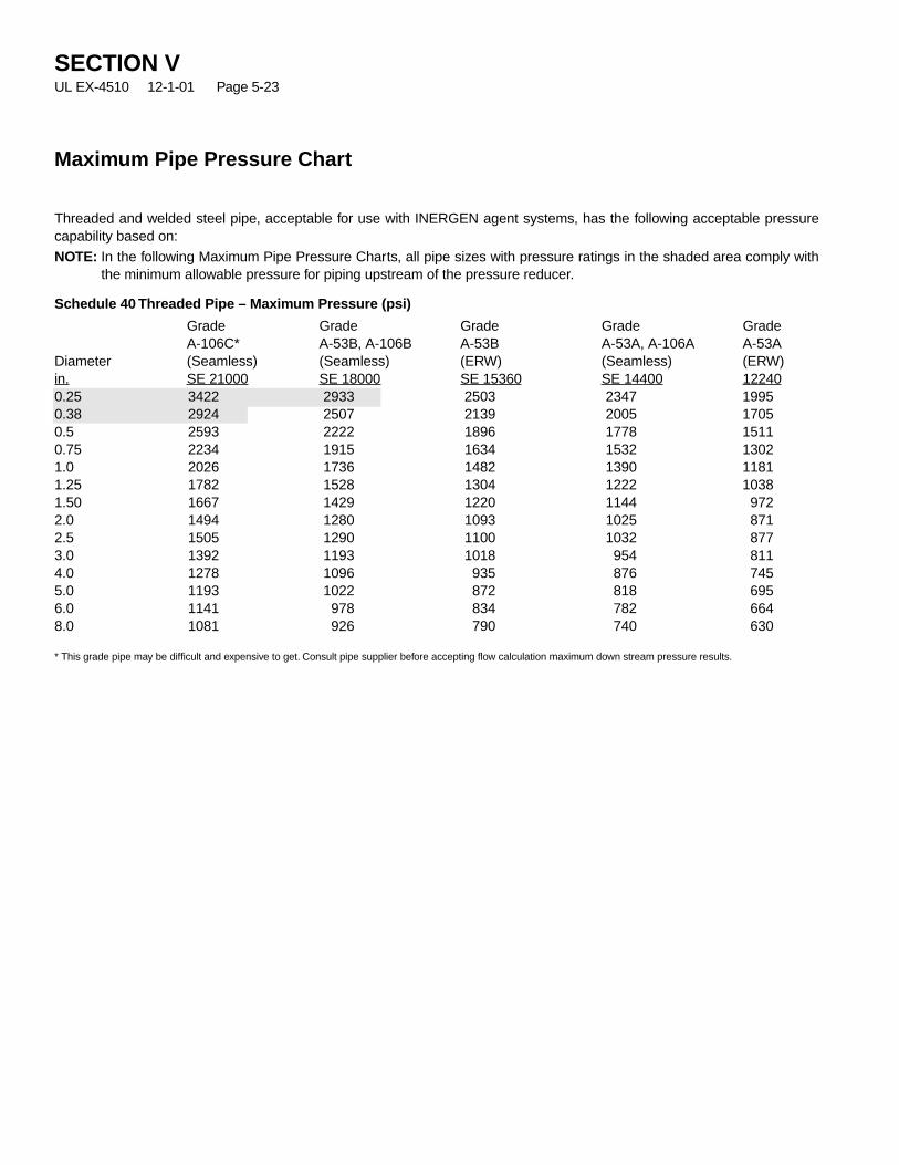
Maximum Pipe Pressure Chart
Threaded and welded steel pipe, acceptable for use with INERGEN agent systems, has the following acceptable pressurecapability based on:
NOTE: In the following Maximum Pipe Pressure Charts, all pipe sizes with pressure ratings in the shaded area comply withthe minimum allowable pressure for piping upstream of the pressure reducer.
Schedule 40 Threaded Pipe – Maximum Pressure (psi)
Grade Grade Grade Grade GradeA-106C* A-53B, A-106B A-53B A-53A, A-106A A-53A
Diameter (Seamless) (Seamless) (ERW) (Seamless) (ERW)in. SE 21000 SE 18000 SE 15360 SE 14400 122400.25 3422 2933 2503 2347 19950.38 2924 2507 2139 2005 17050.5 2593 2222 1896 1778 15110.75 2234 1915 1634 1532 13021.0 2026 1736 1482 1390 11811.25 1782 1528 1304 1222 10381.50 1667 1429 1220 1144 9722.0 1494 1280 1093 1025 8712.5 1505 1290 1100 1032 8773.0 1392 1193 1018 954 8114.0 1278 1096 935 876 7455.0 1193 1022 872 818 6956.0 1141 978 834 782 6648.0 1081 926 790 740 630
* This grade pipe may be difficult and expensive to get. Consult pipe supplier before accepting flow calculation maximum down stream pressure results.
SECTION VUL EX-4510 12-1-01 Page 5-23

Maximum Pipe Pressure Chart
PIPE PRESSURE (Continued)
Schedule 80 Threaded Pipe – Maximum Pressure (psi)Grade Grade Grade Grade GradeA-106C* A-53B, A-106B A-53B A-53A, A-106A A-53A
Diameter (Seamless) (Seamless) (ERW) (Seamless) (ERW)in. SE 21000 SE 18000 SE 15360 SE 14400 122400.25 5833 5000 4267 4000 34000.38 5102 4373 3732 3499 29740.5 4493 3851 3286 3080 26180.75 3874 3320 2833 2657 22581.0 3495 2996 2556 2397 20371.25 3073 2634 2248 2107 17921.5 2883 2472 2110 1978 16812.0 2625 2250 1920 1800 15302.5 2571 2204 1882 1764 14993.0 2400 2057 1756 1645 13994.0 2212 1896 1618 1517 12895.0 2076 1780 1518 1423 12106.0 2105 1804 1540 1442 12268.0 1948 1669 1424 1336 1135
For welded pipe or roll grooved pipe (fitting restricts pressure capability for roll grooved pipe):
Schedule 40 Welded – Maximum Pressure (psi)Grade Grade Grade Grade GradeA-106C* A-53B, A-106B A-53B A-53A, A-106A A-53A
Diameter (Seamless) (Seamless) (ERW) (Seamless) (ERW)in. SE 21000 SE 18000 SE 15360 SE 14400 122400.25 6844 5867 5006 4693 39890.38 5662 4853 4142 3883 33000.5 5450 4672 3986 3737 31760.75 4520 3875 3306 3100 26341.0 4248 3641 3107 2912 24751.25 3542 3036 2591 2429 20641.50 3205 2747 2344 2197 18682.0 2723 2334 1992 1867 15882.5 2965 2542 2168 2033 17283.0 2592 2221 1896 1777 15114.0 2212 1896 1618 1516 12895.0 1948 1669 1424 1336 11356.0 1775 1522 1298 1217 10348.0 1568 1344 1147 1075 914
Schedule 80 Welded – Maximum Pressure (psi)Grade Grade Grade Grade GradeA-106C* A-53B, A-106B A-53B A-53A, A-106A A-53A
Diameter (Seamless) (Seamless) (ERW) (Seamless) (ERW)in. SE 21000 SE 18000 SE 15360 SE 14400 122400.25 9256 7933 6770 6347 53950.38 7840 6720 5734 5376 45700.5 7350 6300 5376 5040 42840.75 6160 5280 4506 4224 3590
* This grade pipe may be difficult and expensive to get. Consult pipe supplier before accepting flow calculation maximum down stream pressure results.
SECTION VUL EX-4510 12-1-01 Page 5-24

PIPE PRESSURE (Continued)
Schedule 80 Welded – Maximum Pressure (psi) (Continued)Grade Grade Grade Grade GradeA-106C* A-53B, A-106B A-53B A-53A, A-106A A-53A
Diameter (Seamless) (Seamless) (ERW) (Seamless) (ERW)in. SE 21000 SE 18000 SE 15360 SE 14400 122401.0 5717 4900 4182 3920 33321.25 4833 4142 3535 3314 28161.5 4421 3789 3234 3032 25762.0 3855 3304 2820 2644 22482.5 4032 3456 2949 2765 23503.0 3600 3086 2633 2469 20984.0 3145 2696 2301 2157 18345.0 2831 2427 2071 1941 16506.0 2739 2347 2003 1878 15968.0 2435 2087 1781 1670 1420
Schedule 160 Threaded Pipe – Maximum Pressure (psi)Grade Grade Grade Grade GradeA-106C* A-53B, A-106B A-53B A-53A, A-106A A-53A
Diameter (Seamless) (Seamless) (ERW) (Seamless) (ERW)in. SE 21000 SE 18000 SE 15360 SE 14400 SE 122400.5 6500 5571 4754 4457 37890.75 6440 5520 4710 4416 37541.0 5749 4928 4205 3942 33511.25 4554 3904 3331 3123 26541.5 4664 3998 4312 3198 27192.0 4828 4138 3531 3310 28142.5 4017 3443 2938 2755 23423.0 4044 3466 2958 2773 23574.0 4023 3448 2942 2758 23455.0 3964 3397 2899 2718 23106.0 3918 3358 2866 2687 22848.0 3925 3364 2871 2691 2288
Schedule 160 Welded Pipe – Maximum Pressure (psi)Grade Grade Grade Grade GradeA-106C* A-53B, A-106B A-53B A-53A, A-106A A-53A
Diameter (Seamless) (Seamless) (ERW) (Seamless) (ERW)in. SE 21000 SE 18000 SE 15360 SE 14400 SE 122400.5 9350 8014 6839 6411 54500.75 8720 7474 6378 5979 50831.0 7985 6844 5840 5475 46541.25 6325 5422 4627 4337 36871.5 6212 5324 4543 4259 36202.0 6066 5199 4437 4159 35352.5 5478 4696 4007 3757 31933.0 5244 4495 3836 3596 30574.0 4956 4248 3625 3398 28895.0 4719 4045 3451 3236 27506.0 4552 3902 3329 3121 26538.0 4412 3782 3227 3025 2571
* This grade pipe may be difficult and expensive to get. Consult pipe supplier before accepting flow calculation maximum down stream pressure results.
Maximum Pipe Pressure Chart
SECTION VUL EX-4510 12-1-01 Page 5-25
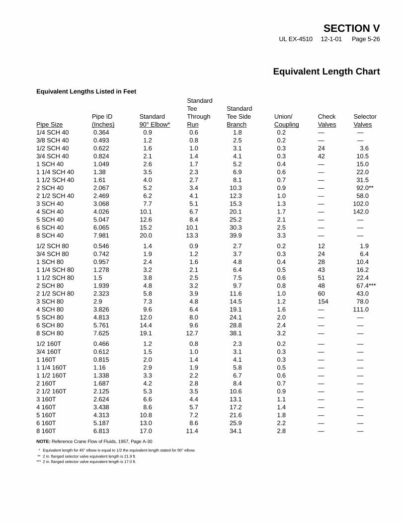
Equivalent Length Chart
Equivalent Lengths Listed in FeetStandardTee Standard
Pipe ID Standard Through Tee Side Union/ Check SelectorPipe Size (Inches) 90° Elbow* Run Branch Coupling Valves Valves1/4 SCH 40 0.364 0.9 0.6 1.8 0.2 — —3/8 SCH 40 0.493 1.2 0.8 2.5 0.2 — —1/2 SCH 40 0.622 1.6 1.0 3.1 0.3 24 3.63/4 SCH 40 0.824 2.1 1.4 4.1 0.3 42 10.51 SCH 40 1.049 2.6 1.7 5.2 0.4 — 15.01 1/4 SCH 40 1.38 3.5 2.3 6.9 0.6 — 22.01 1/2 SCH 40 1.61 4.0 2.7 8.1 0.7 — 31.52 SCH 40 2.067 5.2 3.4 10.3 0.9 — 92.0**2 1/2 SCH 40 2.469 6.2 4.1 12.3 1.0 — 58.03 SCH 40 3.068 7.7 5.1 15.3 1.3 — 102.04 SCH 40 4.026 10.1 6.7 20.1 1.7 — 142.05 SCH 40 5.047 12.6 8.4 25.2 2.1 — —6 SCH 40 6.065 15.2 10.1 30.3 2.5 — —8 SCH 40 7.981 20.0 13.3 39.9 3.3 — —
1/2 SCH 80 0.546 1.4 0.9 2.7 0.2 12 1.93/4 SCH 80 0.742 1.9 1.2 3.7 0.3 24 6.41 SCH 80 0.957 2.4 1.6 4.8 0.4 28 10.41 1/4 SCH 80 1.278 3.2 2.1 6.4 0.5 43 16.21 1/2 SCH 80 1.5 3.8 2.5 7.5 0.6 51 22.42 SCH 80 1.939 4.8 3.2 9.7 0.8 48 67.4***2 1/2 SCH 80 2.323 5.8 3.9 11.6 1.0 60 43.03 SCH 80 2.9 7.3 4.8 14.5 1.2 154 78.04 SCH 80 3.826 9.6 6.4 19.1 1.6 — 111.05 SCH 80 4.813 12.0 8.0 24.1 2.0 — —6 SCH 80 5.761 14.4 9.6 28.8 2.4 — —8 SCH 80 7.625 19.1 12.7 38.1 3.2 — —
1/2 160T 0.466 1.2 0.8 2.3 0.2 — —3/4 160T 0.612 1.5 1.0 3.1 0.3 — —1 160T 0.815 2.0 1.4 4.1 0.3 — —1 1/4 160T 1.16 2.9 1.9 5.8 0.5 — —1 1/2 160T 1.338 3.3 2.2 6.7 0.6 — —2 160T 1.687 4.2 2.8 8.4 0.7 — —2 1/2 160T 2.125 5.3 3.5 10.6 0.9 — —3 160T 2.624 6.6 4.4 13.1 1.1 — —4 160T 3.438 8.6 5.7 17.2 1.4 — —5 160T 4.313 10.8 7.2 21.6 1.8 — —6 160T 5.187 13.0 8.6 25.9 2.2 — —8 160T 6.813 17.0 11.4 34.1 2.8 — —
NOTE: Reference Crane Flow of Fluids, 1957, Page A-30
* Equivalent length for 45° elbow is equal to 1/2 the equivalent length stated for 90° elbow.
** 2 in. flanged selector valve equivalent length is 21.9 ft.*** 2 in. flanged selector valve equivalent length is 17.0 ft.
SECTION VUL EX-4510 12-1-01 Page 5-26
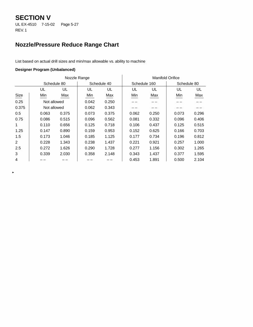
SECTION VUL EX-4510 7-15-02 Page 5-27
REV. 1
List based on actual drill sizes and min/max allowable vs. ability to machine
Designer Program (Unbalanced)
Nozzle Range Manifold Orifice
Schedule 80 Schedule 40 Schedule 160 Schedule 80
UL UL UL UL UL UL UL UL
Size Min Max Min Max Min Max Min Max___ ___ ____ ____ ___ ___ ____ ___ ____
0.25 Not allowed 0.042 0.250 – – – – – – – –
0.375 Not allowed 0.062 0.343 – – – – – – – –
0.5 0.063 0.375 0.073 0.375 0.062 0.250 0.073 0.296
0.75 0.086 0.515 0.096 0.562 0.081 0.332 0.096 0.406
1 0.110 0.656 0.125 0.718 0.106 0.437 0.125 0.515
1.25 0.147 0.890 0.159 0.953 0.152 0.625 0.166 0.703
1.5 0.173 1.046 0.185 1.125 0.177 0.734 0.196 0.812
2 0.228 1.343 0.238 1.437 0.221 0.921 0.257 1.000
2.5 0.272 1.626 0.290 1.728 0.277 1.156 0.302 1.265
3 0.339 2.030 0.358 2.148 0.343 1.437 0.377 1.595
4 – – – – – – – – 0.453 1.891 0.500 2.104
Nozzle/Pressure Reduce Range Chart

SECTION VIUL EX-4510 12-1-01 Page 6-1
All installations are to be performed in accordance with theparameters of this manual and all appropriate codes andstandards from the local, state, and federal authority havingjurisdiction.
Before the INERGEN system is installed, the qualifiedinstaller should develop installation drawings in order tolocate the equipment, to determine an actuation and distrib-ution piping routing, and to develop a bill of material.
For successful system performance, the INERGEN systemcomponents must be located within their approved temper-ature ranges. The ambient temperature range is 32 °F to130 °F (0 °C to 54 °C). All AUTOPULSE Control Systemsare designed for indoor applications and for temperatureranges between 32 °F to 120 °F (0 °C to 49 °C).
MOUNTING COMPONENTS
Cylinder/Bracket Assembly
INERGEN cylinders may be located inside or outside theprotected space, although it is preferable to locate themoutside of the space. They must not be located where theywill be exposed to a fire or explosion in the hazard. Whenthey are installed within the space they protect, a remotemanual control must be installed to release the systemsafely from outside the hazard area.
The cylinders should be installed so that they can be easilyremoved after use for recharging. Cylinders must beinstalled indoors. Do not install the cylinders where they areexposed to direct sun rays. Cylinders may be installed hori-zontal if properly bracketed.
See Figures 1 through 4 for detailed mounting height infor-mation for all cylinder bracketing.
FIGURE 1001868
Installation
ANSUL®
®
Bracketing Without Uprights – Single Cylinder
Clamp Installation – INERGEN Cylinder Assembly
Cylinder Size Dimension A Dimension B Dimension C Dimension Dcu. ft. (cu. m) in. (cm) in. (cm) in. (cm) in. (cm)
570 (16.1) 14 (36) 38 (97) 12 (31) 15 1/8 (38)
B
A
C
MOUNTING HOLES – 2HAVING 11/16 IN. DIAMETER
2 IN. X 1 IN. X 3/16 IN.STEEL CHANNELS
1/2 IN. X 1 1/4 IN. BOLTS ANDNUTS (BOLT HEADS WELDEDTO CHANNELS)
2 IN. X 3/16 IN.STEEL STRAPS
D
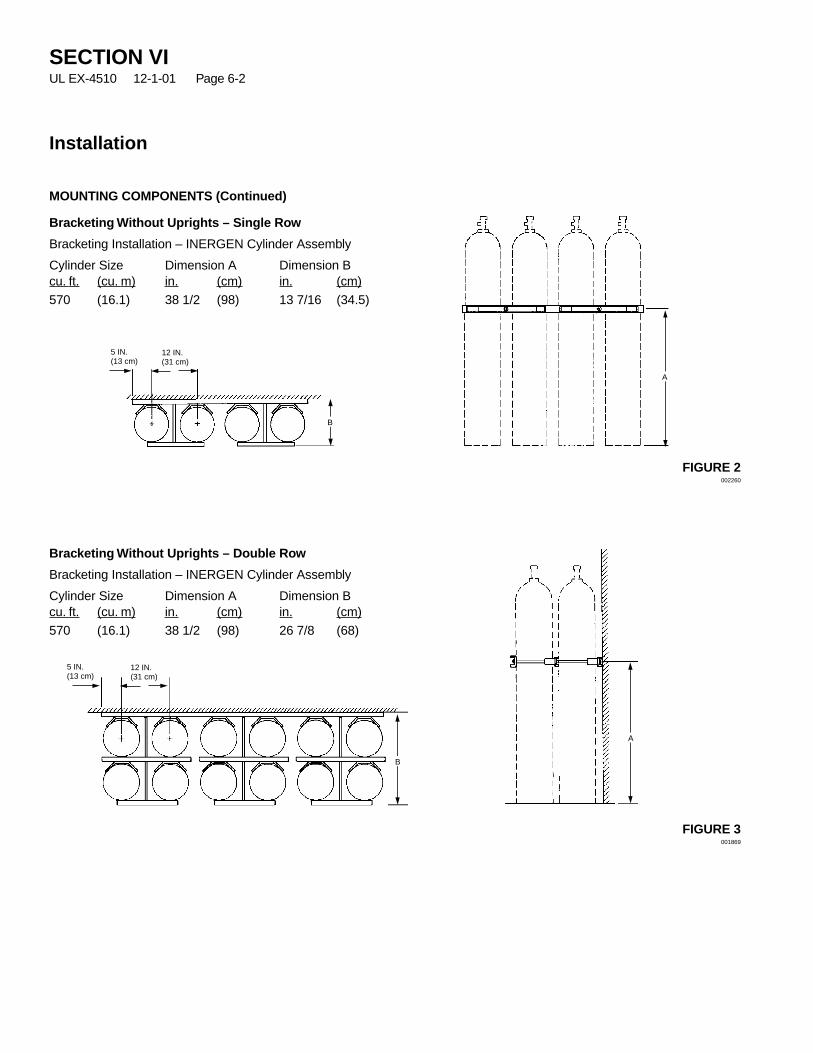
SECTION VIUL EX-4510 12-1-01 Page 6-2
Installation
MOUNTING COMPONENTS (Continued)
Bracketing Without Uprights – Single Row
Bracketing Installation – INERGEN Cylinder Assembly
Cylinder Size Dimension A Dimension Bcu. ft. (cu. m) in. (cm) in. (cm)
570 (16.1) 38 1/2 (98) 13 7/16 (34.5)
Bracketing Without Uprights – Double Row
Bracketing Installation – INERGEN Cylinder Assembly
Cylinder Size Dimension A Dimension Bcu. ft. (cu. m) in. (cm) in. (cm)
570 (16.1) 38 1/2 (98) 26 7/8 (68)
FIGURE 2002260
FIGURE 3001869
A
5 IN.(13 cm)
12 IN.(31 cm)
B
A
5 IN.(13 cm)
12 IN.(31 cm)
B
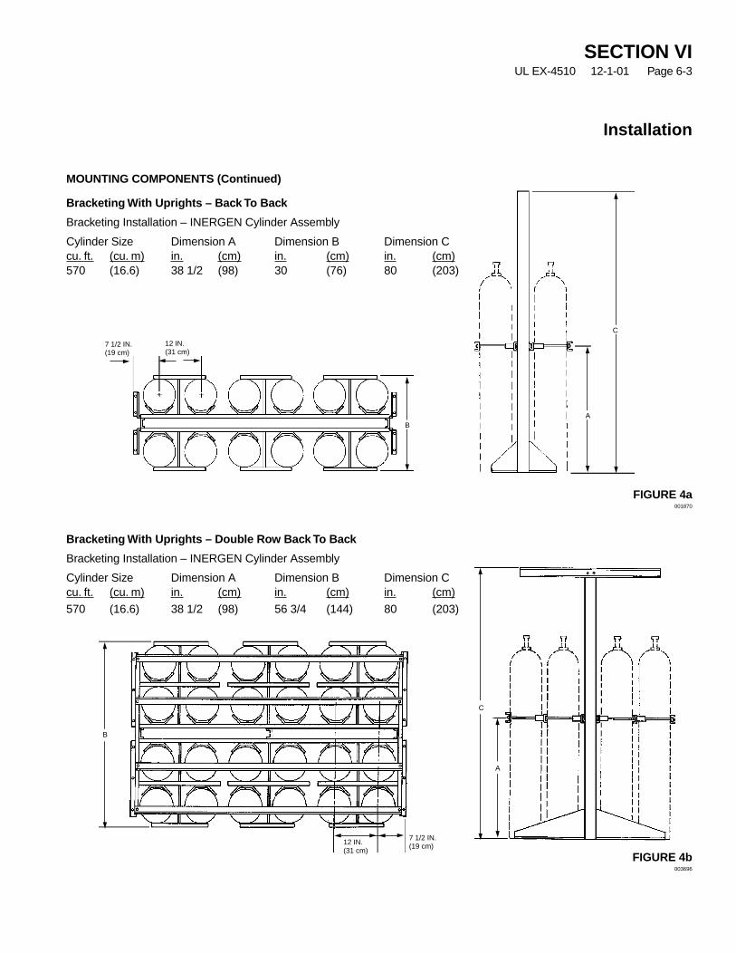
SECTION VIUL EX-4510 12-1-01 Page 6-3
Installation
MOUNTING COMPONENTS (Continued)
Bracketing With Uprights – Back To Back
Bracketing Installation – INERGEN Cylinder Assembly
Cylinder Size Dimension A Dimension B Dimension Ccu. ft. (cu. m) in. (cm) in. (cm) in. (cm)570 (16.6) 38 1/2 (98) 30 (76) 80 (203)
Bracketing With Uprights – Double Row Back To Back
Bracketing Installation – INERGEN Cylinder Assembly
Cylinder Size Dimension A Dimension B Dimension Ccu. ft. (cu. m) in. (cm) in. (cm) in. (cm)
570 (16.6) 38 1/2 (98) 56 3/4 (144) 80 (203)
FIGURE 4b003696
FIGURE 4a001870
A
C
7 1/2 IN.(19 cm)
12 IN.(31 cm)
B
7 1/2 IN.(19 cm)12 IN.
(31 cm)
B
C
A

MOUNTING COMPONENTS (Continued)
1. Mount each INERGEN cylinder by completing the fol-lowing:
a. Assemble bracket components. See Parts List,located in the Appendix Section, for details of cylin-der bracketing and component assembly.
b. If a reserve system is being installed, mount thereserve cylinder(s) directly next to the main systemcylinder(s).
c. Securely mount bracketing to rigid wall or support.
d. Fasten cylinder(s) securely in bracketing.
Releasing Devices
Different types of Releasing/Detection systems are avail-able with the INERGEN system:
– ANSUL AUTOMAN II-C release using thermal detec-tors with pneumatic actuation.
– AUTOPULSE Control System using electric detectionwith electric actuation.
– AUTOPULSE Control System with electric detectionutilizing an ANSUL AUTOMAN II-C release for pneu-matic actuation.
For detailed information on detection systems, refer to thefollowing:
Ansul Detection and Control Application Manual
NFPA 72–National Fire Alarm Code
NFPA 70–National Electrical Code
INSTALLING ACTUATION PIPING
Before installing any actuation piping, the piping designmust be determined. This will confirm that the lengths ofactuation piping does not exceed the maximum allowable.
General Piping Requirements
1. Use only 1/4 in. Schedule 40 black iron, hot-dippedgalvanized, chrome-plated, or stainless steelpipe/braided hose and fittings conforming to ASTMA120, A53, or A106.
2. The maximum length of all 1/4 in. Schedule 40 pipe is100 ft. (30.5 m).
3. Before assembling the pipe and fittings, make certainall ends are carefully reamed and blown clear of chipsand scale. Inside of pipe and fittings must be free of oiland dirt.
4. The piping and fitting connections must be sealed withpipe tape. When applying pipe tape, start at the sec-ond male thread and wrap the tape (two turns maxi-mum) clockwise around the threads, away from thepipe opening.
NOTICE
Do not allow tape to overlap the pipeopening, as this could cause possibleblockage of the gas pressure. Threadsealant or compound must not be used.
5. Cast iron pipe and fittings are not acceptable.
6. Actuation piping must be rigidly supported by UL listedhangers as described on Page 6-6.
SECTION VIUL EX-4510 12-1-01 Page 6-4
Installation
CAUTION
Do not remove the safety shipping caps at thistime. They are provided to prevent accidental actu-ation and discharge during shipping and handling.If valve assembly is accidentally operated, velocityof unrestricted escaping gas is forceful enough tocause injury, especially about the face and head.
CAUTION
Proper fasteners must be used when mountingcylinder bracketing to wall or support. Failure toproperly mount could cause cylinder movementupon discharge.
!
!

SECTION VIUL EX-4510 12-1-01 Page 6-5
Installation
INSTALLING ACTUATION PIPING (Continued)
Actuation Piping Installation
1. Install 1/4 in. Schedule 40 pipe from gas outlet port onthe ANSUL AUTOMAN II-C release to cylinder loca-tion. Use one of the 1/2 in. (1.3 cm) knockouts provid-ed in the top, bottom, or side of the enclosure to exitthe piping.
2. If pneumatic operated accessories are required to beoperated from the actuation pressure, branch off the1/4 in. actuation piping and run to each accessory.
3. Install 1/4 in. tee in the actuation piping approximately24 in. (61 cm) before first INERGEN cylinder andinstall vent plug, Part No. 42175. See Figure 5.
4. Install actuation hose, Part Nos. 31809, 32335, or32336 (depending on length required) between actua-tion piping and either pneumatic actuator or INERGENvalve. A 1/4 in. male connector, Part No. 32338, isrequired on each end of the actuation hose. SeeFigure 5.
5. A 1/4 in. check valve, Part No. 825627, must beinstalled between the 1/4 in. vent plug and theINERGEN cylinder as shown in Figure 5.
FIGURE 5004434
APPROX.24 IN.(61 cm)
CHECKVALVEPART NO.825627
MALEELBOWPARTNO.832334
VALVEACTUATIONADAPTOR,PART NO.873236
1/4 IN.VENT PLUG,PART NO.842175
PRESSURE TRIP,PART NO. 805156
PRESSURESWITCH (SEECOMPONENTSECTION)
CV-98
STRAIGHTADAPTOR –PART NO.832338 (ORELBOWPART NO.831810)
STAINLESS BRAIDED HOSEPART NO. 831809 – 16 IN. (40.6 cm)PART NO. 832335 – 20 IN. (50.8 cm)PART NO. 832336 – 24 IN. (60.9 cm)
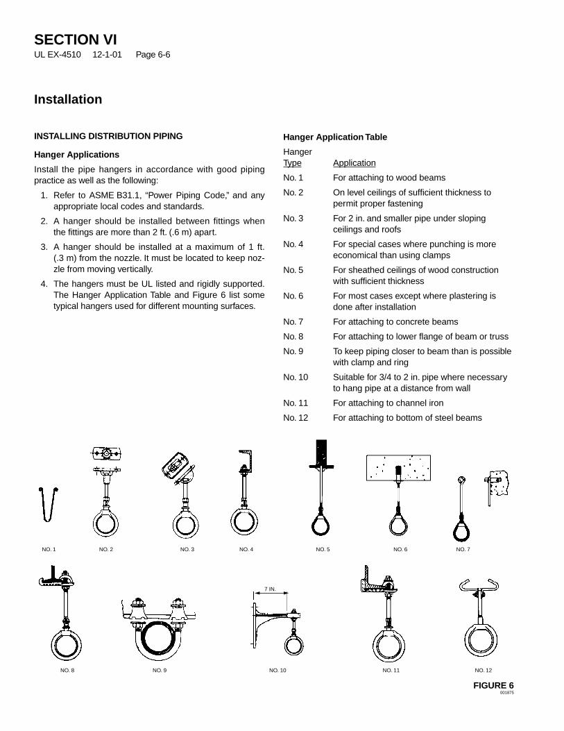
INSTALLING DISTRIBUTION PIPING
Hanger Applications
Install the pipe hangers in accordance with good pipingpractice as well as the following:
1. Refer to ASME B31.1, “Power Piping Code,” and anyappropriate local codes and standards.
2. A hanger should be installed between fittings whenthe fittings are more than 2 ft. (.6 m) apart.
3. A hanger should be installed at a maximum of 1 ft.(.3 m) from the nozzle. It must be located to keep noz-zle from moving vertically.
4. The hangers must be UL listed and rigidly supported.The Hanger Application Table and Figure 6 list sometypical hangers used for different mounting surfaces.
Hanger Application Table
HangerType Application
No. 1 For attaching to wood beams
No. 2 On level ceilings of sufficient thickness topermit proper fastening
No. 3 For 2 in. and smaller pipe under slopingceilings and roofs
No. 4 For special cases where punching is moreeconomical than using clamps
No. 5 For sheathed ceilings of wood constructionwith sufficient thickness
No. 6 For most cases except where plastering isdone after installation
No. 7 For attaching to concrete beams
No. 8 For attaching to lower flange of beam or truss
No. 9 To keep piping closer to beam than is possiblewith clamp and ring
No. 10 Suitable for 3/4 to 2 in. pipe where necessaryto hang pipe at a distance from wall
No. 11 For attaching to channel iron
No. 12 For attaching to bottom of steel beams
FIGURE 6001875
SECTION VIUL EX-4510 12-1-01 Page 6-6
Installation
NO. 1 NO. 2 NO. 3 NO. 4 NO. 5 NO. 6 NO. 7
NO. 8 NO. 9 NO. 10 NO. 11 NO. 12
7 IN.

SECTION VIUL EX-4510 7-15-02 Page 6-7
REV. 1
Installation
INSTALLING DISTRIBUTION PIPING (Continued)
General Piping Requirements
NOTE: Actual grades and sizes will depend on maxi-mum downstream pressure from the flow calcu-lation.
1. All threaded pipe beyond the pressure reducer, orselector valve, if applicable, to be black iron or galva-nized of the following pipe size and grade combina-tions.
ASTM A-106, Sch. 40-through 8 in.Seamless, Grade C
ASTM A-106/A-53 Sch. 40-through 5 in.Seamless, Grade B
ASTM A-106/A-53 Sch. 40-through 2.5 in.Seamless, Grade A
ASTM A-53 ERW, Grade B Sch. 40-through 3 in.
ASTM A-53 ERW, Grade A Sch. 40-through 1.25 in.
2. All threaded pipe used to construct the manifold,including pipe before the pressure reducer, to be blackiron or galvanized of the following pipe size and gradecombinations.
ASTM A-106 Sch. 80-through 1.25 in.Seamless, Grade C
ASTM A-106/A-53 Sch. 80-through 1 in.Seamless, Grade B
ASTM A-106/A-53 Sch. 80-through .5 in.Seamless, Grade A
ASTM A-53 ERW, Grade B Sch. 80-through .5 in.
ASTM A-53 ERW, Grade A Sch. 80-through .38 in.
ASTM A-106 Sch. 160-through 8 in.Seamless, Grade C
ASTM A-106/A-53 Sch. 160-through 8 in.Seamless, Grade B
ASTM A-106/A-53 Sch. 160-through 2 in.Seamless, Grade A
ASTM A-53 ERW, Grade B Sch. 160-through 4 in.
ASTM A-53 ERW, Grade A Sch. 160-through 1 in.
3. All fittings beyond the pressure reducer to be 300 lb.(or higher depending on maximum downstream pres-sure) ANSI B-16.3 black malleable iron or galvanizedthreaded fittings through 3 in. size. Forged steel fittingsto be used for larger sizes. All flanged joints to beClass 600 lb. (Class 300 malleable iron unions orstreet elbows shall not be used.)
4. All fittings used to construct the manifold, including fit-tings before the pressure reducer, to be black iron orgalvanized 2000 or 3000 lb. class ANSI B-16.11.
5. A120 pipe SHALL NOT BE USED.
6. Cylinder and piping to be securely bracketed – espe-cially at the fittings and nozzles.
7. Ream, clean, and blow out all pipe before installing.
8. All dead end pipe lines to be provided with a cappednipple, 2 in. long. See Figure 7.
FIGURE 7001876
9. All pipe lengths are measured center to center of fit-tings.
10. All distribution pipe and fittings must be assembledusing either pipe tape or pipe dope. Do not add to thefirst two threads nearest the end of the pipe.
11. Install pressure reducer/union in the piping with theorifice identification tab on the pressure inlet side ofthe system. The 1 1/4 in., 1 1/2 in., and 2 in. pressurereducer/union must be installed per the direction of theflow arrow stamped on the body.
12. Critical length from pressure reducer to first tee mustbe a minimum of 10 nominal pipe diameter.
13. Refer to “Pipe Pressure Rating Chart,” Pages 5-23 –5-25, in Design section for selection of the correctpressure rated pipe.
14. Size reductions can be accomplished with the use ofreducing bushings, reducing couplings, reducing tees,or reducing elbows.
15. Bushing up (increasing pipe size) in the downstreampiping is acceptable immediately after the pressurereducer only. Increase in size can be no greater thantwo nominal pipe sizes. Only the use of a close nippleand reducing coupling or a swaged nipple can be used.
16. Pressure reducer must be the same size as thesystem manifold outlet pipe size.
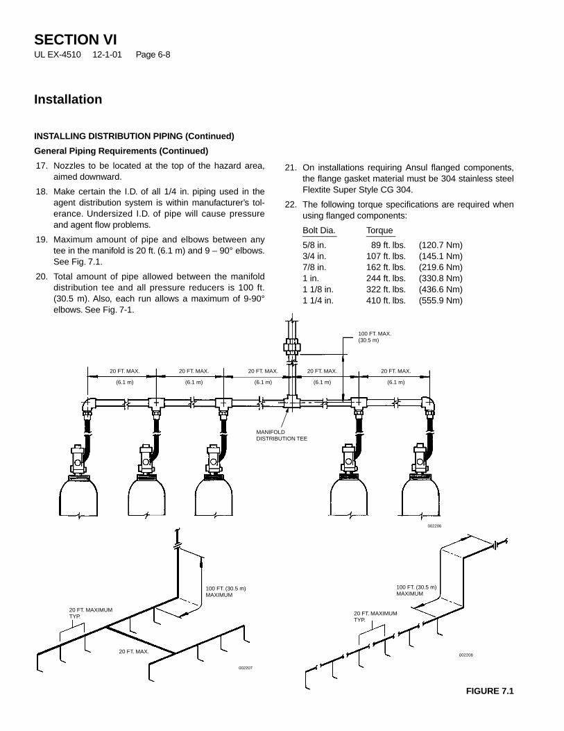
21. On installations requiring Ansul flanged components,the flange gasket material must be 304 stainless steelFlextite Super Style CG 304.
22. The following torque specifications are required whenusing flanged components:
Bolt Dia. Torque_______ ______
5/8 in. 89 ft. lbs. (120.7 Nm)3/4 in. 107 ft. lbs. (145.1 Nm)7/8 in. 162 ft. lbs. (219.6 Nm)1 in. 244 ft. lbs. (330.8 Nm)1 1/8 in. 322 ft. lbs. (436.6 Nm)1 1/4 in. 410 ft. lbs. (555.9 Nm)
FIGURE 7.1
INSTALLING DISTRIBUTION PIPING (Continued)
General Piping Requirements (Continued)
17. Nozzles to be located at the top of the hazard area,aimed downward.
18. Make certain the I.D. of all 1/4 in. piping used in theagent distribution system is within manufacturer’s tol-erance. Undersized I.D. of pipe will cause pressureand agent flow problems.
19. Maximum amount of pipe and elbows between anytee in the manifold is 20 ft. (6.1 m) and 9 – 90° elbows.See Fig. 7.1.
20. Total amount of pipe allowed between the manifolddistribution tee and all pressure reducers is 100 ft.(30.5 m). Also, each run allows a maximum of 9-90°elbows. See Fig. 7-1.
SECTION VIUL EX-4510 12-1-01 Page 6-8
Installation
20 FT. MAX.
(6.1 m)
20 FT. MAX.
(6.1 m)
20 FT. MAX.
(6.1 m)
MANIFOLDDISTRIBUTION TEE
20 FT. MAX.
(6.1 m)
20 FT. MAX.
(6.1 m)
100 FT. MAX.(30.5 m)
002206
002207
20 FT. MAX.
20 FT. MAXIMUMTYP.
100 FT. (30.5 m)MAXIMUM
20 FT. MAXIMUMTYP.
100 FT. (30.5 m)MAXIMUM
002208

SECTION VIUL EX-4510 12-1-01 Page 6-9
Installation
INSTALLING DISTRIBUTION PIPING (Continued)
Distribution Manifold And Piping
1. Starting with the cylinder manifold, securely mount themanifold at the appropriate height as shown in Figure8. Make certain that if accessories piping is to be donelater that the end of the manifold contains a teeinstead of an elbow. The outlet of the tee will later bereduced down to 1/4 in. for piping to the accessories.
1 Cylinder 2 Cylinders 3 Cylinders
Manifold Height and Spacings
Cylinder Size Dimension A Dimension B Dimension C Dimension D Dimension Ecu. ft. (cu. m) in. (cm) in. (cm) in. (cm) in. (cm) in. (cm)
570 (16.1) 79 (201) 79 1/2 (202) 12 (31) 12 (31) 12 (31)
A
A
B
C D C
E EE
SUPPLY PIPESUPPLY PIPE
1/2 IN. ELBOW“Y” FITTING
INERGENVALVE
FLEXIBLEDISCHARGEBEND,PART NO.427082
FLEXIBLEDISCHARGEBEND,PART NO.427082
SUPPLY PIPE HEADER
FIGURE 8002209

INSTALLING DISTRIBUTION PIPING (Continued)
Distribution and Manifold Piping (Continued)
2. The maximum number of cylinders that can be backpressure actuated from a pilot or set of pilot cylindersis 40. When more than 40 cylinders are required, up to12 additional sets of pilot cylinders (each operating 40cylinders) can be pneumatically actuated from a pilotmanifold. See Figure 8.1.
The installation guidelines that must be followed are:
• 1/4 in. Schedule 80 pipe ASTM A-53 ERW or seam-less grade A or B, or Grades A106 A, B or C and2000/3000 lb. class fittings (ANSI B-16.11) must beused on actuation manifold.
• Maximum length of actuation manifold is 55 ft.(16.8 m).
• Maximum of 12 pilots valves can be actuated fromactuation manifold.
• Actuation manifold must start from pilot manifold asfar from the distribution pressure reducer as possible.
• The actuated pilot valve must be located in thedistribution manifold as far from the distributionpressure reducer as possible.
• When piping the actuation manifold to the pilotvalve(s), use Straight Adaptor, Part No. 832338 (orelbow Part No. 831810), Stainless Braided Hose,Part No. 831809, 832335, or 832336, Male Elbow,Part No. 832334, and Valve Actuation Adaptor, PartNo. 873236.
• Refer to Step No. 25, “Additional Secondary PilotCylinder Requirements” in Design Section, for addi-tional design information.
FIGURE 8.1002210
INSTALLING DISTRIBUTION PIPING (Continued)
SECTION VIUL EX-4510 12-1-01 Page 6-10
Installation
START ACTUATION MANIFOLDAS FAR FROM PRESSUREREDUCER AS POSSIBLE
ACTUATIONMANIFOLD
12 2 1 1 40
VALVE ACTUATION ADAPTOR– PART NO. 873236
STRAIGHT ADAPTOR – PART NO. 832338(OR ELBOW PART NO. 831810)
STAINLESS BRAIDED HOSEPART NO. 831809 – 16 IN. (40.6 cm)PART NO. 832335 – 20 IN. (50.8 cm)PART NO. 832336 – 24 IN. (60.9 cm)
LOCATE PILOT VALVE INDISTRIBUTION MANIFOLD ON ENDOPPOSITE OF PRESSURE REDUCER
DISTRIBUTION MANIFOLD
PRESSUREREDUCER
NOTE: SEE STEP NO. 2FOR ADDITIONALINFORMATION
MAXIMUM OF 55 FT. (16.8 m) 1/4 IN. PIPING
MALE ELBOW– PART NO. 832334
CHECK VALVE

SECTION VIUL EX-4510 12-1-01 Page 6-11
Installation
Distribution Manifold And Piping (Continued)
3. Continue piping remainder of the distribution piping,following piping sketch and computer design complet-ed in System Design Section. When installing a selec-tor valve in the piping system, make certain of the fol-lowing:
• Selector valve is installed with either a manual actu-ator or a brass cap on the upper actuator threads.See Component Sheet, Page 1-8 for Part Nos. oflever actuators.
• Make certain valve is installed in the correct flowdirection.
NOTICE
All piping shall be laid out to reduce fric-tion losses to a reasonable minimum andcare shall be taken to avoid possiblerestrictions due to foreign matter or faultyfabrication.
4. Install discharge nozzles as specified on the computerdesign piping output sheet.
5. Install male end of flexible discharge bend, Part No.427082, into each manifold inlet. Wrench tighten.
6. With cylinders securely mounted in bracket, attachfemale end of flexible discharge bend unto cylindervalve outlet. Wrench tighten.
7. If accessory piping is required, see Installing Acces-sories, for detailed piping information.
MAIN/RESERVE SYSTEM
When piping a connected reserve system, the reservecylinders must be segregated from the pressure of the mainsystem. This is accomplished by adding check valves in thedistribution manifold. It is also necessary to install a headervent plug on each side of the manifold. This is requiredbecause of the addition of the check valves in the manifold.See Figure 9.
FIGURE 9002211
HEADER VENTPLUG
HEADER VENTPLUG
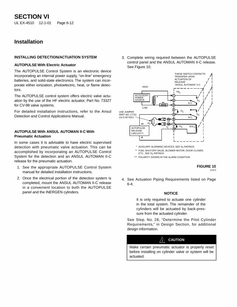
INSTALLING DETECTION/ACTUATION SYSTEM
AUTOPULSE With Electric Actuator
The AUTOPULSE Control System is an electronic deviceincorporating an internal power supply, “on-line” emergencybatteries, and solid-state electronics. The system can incor-porate either ionization, photoelectric, heat, or flame detec-tors.
The AUTOPULSE control system offers electric valve actu-ation by the use of the HF electric actuator, Part No. 73327for CV-98 valve systems.
For detailed installation instructions, refer to the AnsulDetection and Control Applications Manual.
AUTOPULSE With ANSUL AUTOMAN II-C WithPneumatic Actuation
In some cases it is advisable to have electric superviseddetection with pneumatic valve actuation. This can beaccomplished by incorporating an AUTOPULSE ControlSystem for the detection and an ANSUL AUTOMAN II-Crelease for the pneumatic actuation.
1. See the appropriate AUTOPULSE Control Systemmanual for detailed installation instructions.
2. Once the electrical portion of the detection system iscompleted, mount the ANSUL AUTOMAN II-C releasein a convenient location to both the AUTOPULSEpanel and the INERGEN cylinders.
3. Complete wiring required between the AUTOPULSEcontrol panel and the ANSUL AUTOMAN II-C release.See Figure 10.
FIGURE 10001879
4. See Actuation Piping Requirements listed on Page6-4.
NOTICE
It is only required to actuate one cylinderin the total system. The remainder of thecylinders will be actuated by back-pres-sure from the actuated cylinder.
See Step. No. 28, “Determine the Pilot CylinderRequirements,” in Design Section, for additionaldesign information.
SECTION VIUL EX-4510 12-1-01 Page 6-12
Installation
CAUTION!
Make certain pneumatic actuator is properly resetbefore installing on cylinder valve or system will beactuated.
ACCESSORYPOWERSOURCE
AUTOPULSERELEASECIRCUIT***
LOW
HIGH
Rx
N.C.
N.C.S1
D1
J1
TB1
SOL1
S2
D2
USE JUMPERPART NO. 17761(12.5-30 VDC)
THESE SWITCH CONTACTSTRANSFER UPONACTUATION OFRELEASE“ANSUL AUTOMAN” II-C
* AUXILIARY ALARMING DEVICES, SEE S1 RATINGS
** FUEL SHUT-OFF VALVE, BLOWER MOTOR, DOOR CLOSER,ETC., SEE S1 RATINGS
*** POLARITY SHOWN IN THE ALARM CONDITION
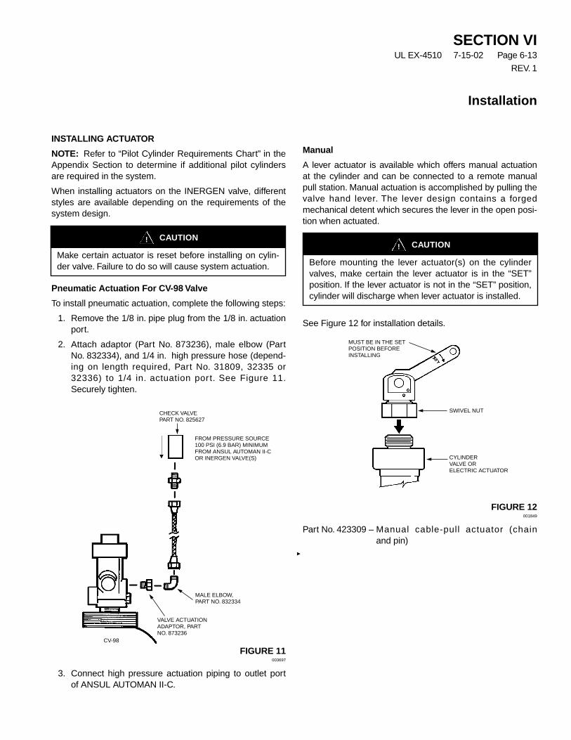
SECTION VIUL EX-4510 7-15-02 Page 6-13
REV. 1
Installation
INSTALLING ACTUATOR
NOTE: Refer to “Pilot Cylinder Requirements Chart” in theAppendix Section to determine if additional pilot cylindersare required in the system.
When installing actuators on the INERGEN valve, differentstyles are available depending on the requirements of thesystem design.
Pneumatic Actuation For CV-98 Valve
To install pneumatic actuation, complete the following steps:
1. Remove the 1/8 in. pipe plug from the 1/8 in. actuationport.
2. Attach adaptor (Part No. 873236), male elbow (PartNo. 832334), and 1/4 in. high pressure hose (depend-ing on length required, Part No. 31809, 32335 or32336) to 1/4 in. actuation port. See Figure 11.Securely tighten.
FIGURE 11003697
3. Connect high pressure actuation piping to outlet portof ANSUL AUTOMAN II-C.
Manual
A lever actuator is available which offers manual actuationat the cylinder and can be connected to a remote manualpull station. Manual actuation is accomplished by pulling thevalve hand lever. The lever design contains a forgedmechanical detent which secures the lever in the open posi-tion when actuated.
See Figure 12 for installation details.
FIGURE 12001849
Part No. 423309 – Manual cable-pull actuator (chain and pin)
CAUTION!
Make certain actuator is reset before installing on cylin-der valve. Failure to do so will cause system actuation.
FROM PRESSURE SOURCE100 PSI (6.9 BAR) MINIMUMFROM ANSUL AUTOMAN II-COR INERGEN VALVE(S)
CHECK VALVEPART NO. 825627
CV-98
MALE ELBOW,PART NO. 832334
VALVE ACTUATIONADAPTOR, PARTNO. 873236
CAUTION!
Before mounting the lever actuator(s) on the cylindervalves, make certain the lever actuator is in the “SET”position. If the lever actuator is not in the “SET” position,cylinder will discharge when lever actuator is installed.
MUST BE IN THE SETPOSITION BEFOREINSTALLING
SWIVEL NUT
CYLINDERVALVE ORELECTRIC ACTUATOR
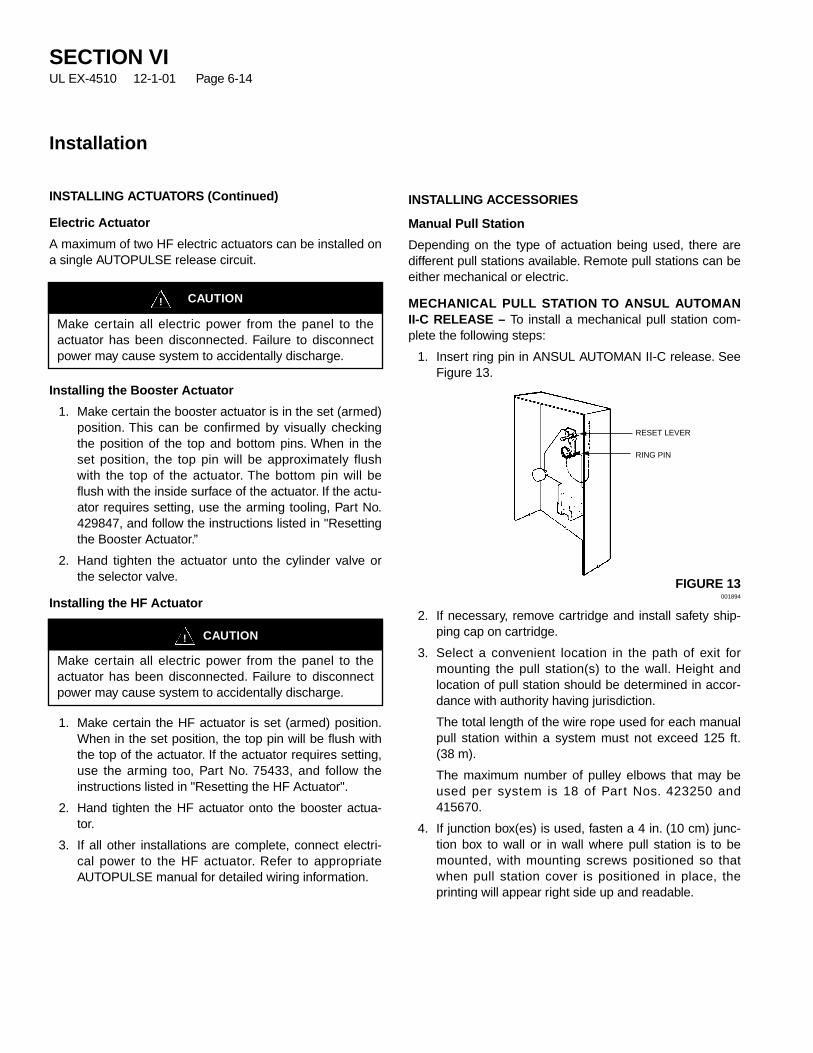
INSTALLING ACTUATORS (Continued)
Electric Actuator
A maximum of two HF electric actuators can be installed ona single AUTOPULSE release circuit.
Installing the Booster Actuator
1. Make certain the booster actuator is in the set (armed)position. This can be confirmed by visually checkingthe position of the top and bottom pins. When in theset position, the top pin will be approximately flushwith the top of the actuator. The bottom pin will beflush with the inside surface of the actuator. If the actu-ator requires setting, use the arming tooling, Part No.429847, and follow the instructions listed in "Resettingthe Booster Actuator.”
2. Hand tighten the actuator unto the cylinder valve orthe selector valve.
Installing the HF Actuator
1. Make certain the HF actuator is set (armed) position.When in the set position, the top pin will be flush withthe top of the actuator. If the actuator requires setting,use the arming too, Part No. 75433, and follow theinstructions listed in "Resetting the HF Actuator".
2. Hand tighten the HF actuator onto the booster actua-tor.
3. If all other installations are complete, connect electri-cal power to the HF actuator. Refer to appropriateAUTOPULSE manual for detailed wiring information.
INSTALLING ACCESSORIES
Manual Pull Station
Depending on the type of actuation being used, there aredifferent pull stations available. Remote pull stations can beeither mechanical or electric.
MECHANICAL PULL STATION TO ANSUL AUTOMANII-C RELEASE – To install a mechanical pull station com-plete the following steps:
1. Insert ring pin in ANSUL AUTOMAN II-C release. SeeFigure 13.
FIGURE 13001894
2. If necessary, remove cartridge and install safety ship-ping cap on cartridge.
3. Select a convenient location in the path of exit formounting the pull station(s) to the wall. Height andlocation of pull station should be determined in accor-dance with authority having jurisdiction.
The total length of the wire rope used for each manualpull station within a system must not exceed 125 ft.(38 m).
The maximum number of pulley elbows that may beused per system is 18 of Part Nos. 423250 and415670.
4. If junction box(es) is used, fasten a 4 in. (10 cm) junc-tion box to wall or in wall where pull station is to bemounted, with mounting screws positioned so thatwhen pull station cover is positioned in place, theprinting will appear right side up and readable.
SECTION VIUL EX-4510 12-1-01 Page 6-14
Installation
CAUTION!
Make certain all electric power from the panel to theactuator has been disconnected. Failure to disconnectpower may cause system to accidentally discharge.
CAUTION!
Make certain all electric power from the panel to theactuator has been disconnected. Failure to disconnectpower may cause system to accidentally discharge.
RESET LEVER
RING PIN

SECTION VIUL EX-4510 12-1-01 Page 6-15
Installation
INSTALLING ACCESSORIES (Continued)
Manual Pull Station (Continued)
ALTERNATE METHOD OF CONNECTION:
a. Thread 3/4 x 1/2 in. reducing coupling to bushing onback of each cover assembly.
b. Mount pull station cover(s) directly to wall at select-ed location so that printing is right side up and read-able.
5. Install and secure 1/2 in. conduit, pulley tee (ifrequired), and pulley elbows from each pull station torelease assembly as necessary. See Figure 14.
FIGURE 14002262
If a pulley tee is used, it must be installed between therelease assembly and first pulley elbow. The ambienttemperature range of the pulley tee is between 32 °Fto 130 °F (0 °C to 54 °C).
6. Feed wire rope from each pull station through conduitand each pulley elbow to cable lever located at releaseassembly.
NOTICE
Make certain that wire rope rides on topand in center of pulley sheave. If the wirerope has been spliced to accommodate alonger run, do not allow the spliced endsto be within 12 in. (30 cm) of any pulleyelbow or conduit adaptor.
7. Fasten pull station assembly to each junction box (ifjunction box is used).
8. Thread wire rope through rear guide hole in manualtrip lever on release. See Figure 14.
9. Pull all slack out of wire rope and thread end throughsleeve, Part No. 4596.
10. Loop the wire rope back up around and through top ofsleeve.
11. Position sleeve approximately 1/2 in. (1.3 cm) andcrimp to secure wire rope. (Use the NationalTelephone Supply Company Nicopress Sleeve toolStock No. 51-C-887 or equal to properly crimp stopsleeve.) See Figure 14.
MECHANICAL PULL STATION TO LEVER RELEASE –To install a mechanical pull station complete the followingsteps:
1. Select a convenient location in the path of exit formounting the pull station(s) to the wall. Height andlocation of pull station should be determined in accor-dance with authority having jurisdiction.
The total length of the wire rope used for each manualpull station within a system must not exceed 125 ft. (38m).
The maximum number of pulley elbows that may beused per system is 10.
2. Install and secure 1/2 in. conduit, dual/triple junctionbox, and pulley elbows from each pull station torelease assembly as necessary.
3. Feed wire rope from pull station through conduit andeach pulley elbow to cable lever located at releaseassembly.
NOTICE
Make certain that wire rope rides on topand in center of pulley sheave. If the wirerope has been spliced to accommodate alonger run, do not allow the spliced endsto be within 12 in. (30 cm) of any pulleyelbow or conduit adaptor.
4. Fasten pull station assembly to each junction box (ifjunction box is used).
5. Wire or pin the actuator lever in the ‘‘SET’’ position toprevent accidental discharge when installing the cable.See Figure 15.
CAUTION!
Wire or pin the actuator lever in the ‘‘SET’’ positionbefore connecting the cable to the lever. Failure tocomply could result in accidental agent discharge.
SEEDETAIL “A”
DETAIL “A”
1/2 IN.
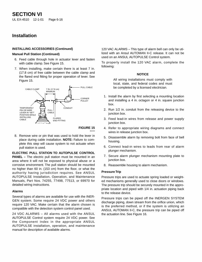
INSTALLING ACCESSORIES (Continued)
Manual Pull Station (Continued)
6. Feed cable through hole in actuator lever and fastenwith cable clamp. See Figure 15.
7. When installing, make certain there is at least 7 in.(17.8 cm) of free cable between the cable clamp andthe flared end fitting for proper operation of lever. SeeFigure 15.
FIGURE 15002220
8. Remove wire or pin that was used to hold the lever inplace during cable installation. NOTE: Failure to com-plete this step will cause system to not actuate whenpull station is used.
ELECTRIC PULL STATION TO AUTOPULSE CONTROLPANEL – The electric pull station must be mounted in anarea where it will not be exposed to physical abuse or acorrosive environment. The pull station should be mountedno higher than 60 in. (153 cm) from the floor, or what theauthority having jur isdiction requires. See ANSULAUTOPULSE Installation, Operation, and MaintenanceManuals, Part Nos. 74255, 77498, 77513, or 69970 fordetailed wiring instructions.
Alarms
Several types of alarms are available for use with the INER-GEN system. Some require 24 VDC power and othersrequire 120 VAC. Make certain that the alarm chosen iscompatible with the detection system control panel used.
24 VDC ALARMS – All alarms used with the ANSULAUTOPULSE Control system require 24 VDC power. Seethe Component Index in the appropriate ANSULAUTOPULSE installation, operation, and maintenancemanual for description of available alarms.
120 VAC ALARMS – This type of alarm bell can only be uti-lized with an Ansul AUTOMAN II-C release. It can not beused on an ANSUL AUTOPULSE Control system.
To properly install the 120 VAC alarm, complete thefollowing:
NOTICE
All wiring installations must comply withlocal, state, and federal codes and mustbe completed by a licensed electrician.
1. Install the alarm by first selecting a mounting locationand installing a 4 in. octagon or 4 in. square junctionbox.
2. Run 1/2 in. conduit from the releasing device to thejunction box.
3. Feed lead-in wires from release and power supplyjunction box.
4. Refer to appropriate wiring diagrams and connectwires in release junction box.
5. Disassemble alarm by removing bolt from face of bellhousing.
6. Connect lead-in wires to leads from rear of alarmplunger mechanism.
7. Secure alarm plunger mechanism mounting plate tojunction box.
8. Reassemble housing to alarm mechanism.
Pressure Trip
Pressure trips are used to actuate spring loaded or weight-ed mechanisms generally used to close doors or windows.The pressure trip should be securely mounted in the appro-priate location and piped with 1/4 in. actuation piping backto the release device.
Pressure trips can be piped off the INERGEN SYSTEMdischarge piping, down stream from the orifice union, whichis the preferred method, or if the system is utilizing anANSUL AUTOMAN II-C, the pressure trip can be piped offthe actuation line. See Figure 16.
SECTION VIUL EX-4510 12-1-01 Page 6-16
Installation
CABLE CLAMPPULL CABLE
PULLCABLE
CONDUIT
7 IN. (17.8 cm)MINIMUM
FLAREDEND FITTING
TEMPORARILYPIN OR WIRELEVER IN “SET”POSITION WHILEINSTALLINGCABLE
CORNERPULLEY
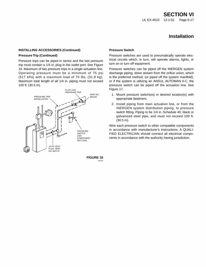
SECTION VIUL EX-4510 12-1-01 Page 6-17
Installation
INSTALLING ACCESSORIES (Continued)
Pressure Trip (Continued)
Pressure trips can be piped in series and the last pressuretrip must contain a 1/4 in. plug in the outlet port. See Figure16. Maximum of two pressure trips in a single actuation line.Operating pressure must be a minimum of 75 psi(517 kPa) with a maximum load of 70 lbs. (31.8 kg).Maximum total length of all 1/4 in. piping must not exceed100 ft. (30.5 m).
FIGURE 16001903
Pressure Switch
Pressure switches are used to pneumatically operate elec-trical circuits which, in turn, will operate alarms, lights, orturn on or turn off equipment.
Pressure switches can be piped off the INERGEN systemdischarge piping, down stream from the orifice union, whichis the preferred method, (or piped off the system manifold),or if the system is utilizing an ANSUL AUTOMAN II-C, thepressure switch can be piped off the actuation line. SeeFigure 17.
1. Mount pressure switch(es) in desired location(s) withappropriate fasteners.
2. Install piping from main actuation line, or from theINERGEN system distribution piping, to pressureswitch fitting. Piping to be 1/4 in. Schedule 40, black orgalvanized steel pipe, and must not exceed 100 ft.(30.5 m).
Wire each pressure switch to other compatible componentsin accordance with manufacturer’s instructions. A QUALI-FIED ELECTRICIAN should connect all electrical compo-nents in accordance with the authority having jurisdiction.
PRESSURE TRIPINSTALLATION
PRESSURESWITCH(SEECOMPONENTSECTION)
1/4 IN. VENTPLUG, PARTNO. 842175
PLUG LASTPRESSURE TRIP
PART NO.805156
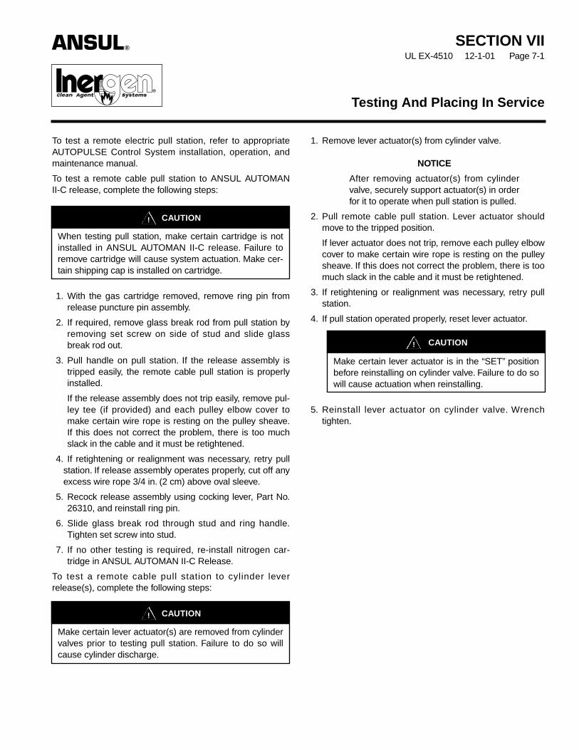
To test a remote electric pull station, refer to appropriateAUTOPULSE Control System installation, operation, andmaintenance manual.
To test a remote cable pull station to ANSUL AUTOMANII-C release, complete the following steps:
1. With the gas cartridge removed, remove ring pin fromrelease puncture pin assembly.
2. If required, remove glass break rod from pull station byremoving set screw on side of stud and slide glassbreak rod out.
3. Pull handle on pull station. If the release assembly istripped easily, the remote cable pull station is properlyinstalled.
If the release assembly does not trip easily, remove pul-ley tee (if provided) and each pulley elbow cover tomake certain wire rope is resting on the pulley sheave.If this does not correct the problem, there is too muchslack in the cable and it must be retightened.
4. If retightening or realignment was necessary, retry pullstation. If release assembly operates properly, cut off anyexcess wire rope 3/4 in. (2 cm) above oval sleeve.
5. Recock release assembly using cocking lever, Part No.26310, and reinstall ring pin.
6. Slide glass break rod through stud and ring handle.Tighten set screw into stud.
7. If no other testing is required, re-install nitrogen car-tridge in ANSUL AUTOMAN II-C Release.
To test a remote cable pull station to cylinder leverrelease(s), complete the following steps:
1. Remove lever actuator(s) from cylinder valve.
NOTICE
After removing actuator(s) from cylindervalve, securely support actuator(s) in orderfor it to operate when pull station is pulled.
2. Pull remote cable pull station. Lever actuator shouldmove to the tripped position.
If lever actuator does not trip, remove each pulley elbowcover to make certain wire rope is resting on the pulleysheave. If this does not correct the problem, there is toomuch slack in the cable and it must be retightened.
3. If retightening or realignment was necessary, retry pullstation.
4. If pull station operated properly, reset lever actuator.
5. Reinstall lever actuator on cylinder valve. Wrenchtighten.
Testing And Placing In Service
SECTION VIIUL EX-4510 12-1-01 Page 7-1
ANSUL®
®
CAUTION!
When testing pull station, make certain cartridge is notinstalled in ANSUL AUTOMAN II-C release. Failure toremove cartridge will cause system actuation. Make cer-tain shipping cap is installed on cartridge.
CAUTION!
Make certain lever actuator(s) are removed from cylindervalves prior to testing pull station. Failure to do so willcause cylinder discharge.
CAUTION!
Make certain lever actuator is in the “SET” positionbefore reinstalling on cylinder valve. Failure to do sowill cause actuation when reinstalling.
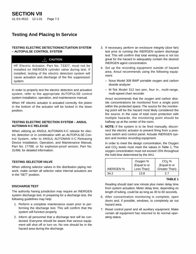
TESTING ELECTRIC DETECTION/ACTUATION SYSTEM– AUTOPULSE CONTROL SYSTEM
In order to properly test the electric detection and actuationsystem, refer to the appropriate AUTOPULSE controlsystem installation, operation, and maintenance manual.
When HF electric actuator is actuated correctly, the pistonin the bottom of the actuator will be locked in the downposition.
TESTING ELECTRIC DETECTION SYSTEM – ANSULAUTOMAN II-C RELEASE
When utilizing an ANSUL AUTOMAN II-C release for elec-tric detection or in combination with an AUTOPULSE Con-trol System, refer to ANSUL AUTOMAN II-C ReleasingDevice Installation, Operation, and Maintenance Manual,Part No. 17788, or for explosion-proof version, Part No.31496, for detailed information.
TESTING SELECTOR VALVE
When utilizing selector valves in the distribution piping net-work, make certain all selector valve internal actuators arein the “SET” position.
DISCHARGE TEST
The authority having jurisdiction may require an INERGENsystem discharge test. In preparing for a discharge test, thefollowing guidelines may help:
1. Perform a complete maintenance exam prior to per-forming the discharge test. This will confirm that thesystem will function properly.
2. Inform all personnel that a discharge test will be con-ducted. Everyone should be aware that various equip-ment will shut off or turn on. No one should be in thehazard area during the discharge.
3. If necessary, perform an enclosure integrity (door fan)test prior to running the INERGEN system dischargetest. This will confirm that total venting area is not toogreat for the hazard to adequately contain the desiredINERGEN agent concentration.
4. Set up the recording equipment outside of hazardarea. Ansul recommends using the following equip-ment:
– Nova Model 308 BWP portable oxygen and carbondioxide analyzer
– M-Tek Model 312 two pen, four in., multi-range,multi-speed chart recorder
Ansul recommends that the oxygen and carbon diox-ide concentrations be monitored from a single pointwithin the protected space. The source for the monitor-ing point will be the hazard most likely considered thefire source. In the case of total room protection withmultiple hazards, the monitoring point should behalfway up at the center of the room.
5. NOTE: If the system is to be fired manually, discon-nect the electric actuator to prevent firing from a pres-sure switch and control panel. Actuate INERGEN sys-tem and monitor recording equipment.
In order to meet the design concentration, the Oxygenand CO2 levels must meet the values in Table 1. Theoxygen concentration must not exceed 15% throughoutthe hold time determined by the AHJ.
TABLE 1
Reading should start one minute plus meter delay timefrom system actuation. Meter delay time, depending onlength of tubing, could be as long as 30 to 60 seconds.
6. After concentration monitoring is complete, opendoors and, if possible, windows, to completely air outhazard area.
7. Reset control panel and all auxiliary equipment. Makecertain all equipment has returned to its normal oper-ating status.
SECTION VIIUL EX-4510 12-1-01 Page 7-2
Testing And Placing In Service
CAUTION!
HF Electric Actuator, Part No. 73327, must not beinstalled on INERGEN cylinder valve during test. Ifinstalled, testing of the electric detection system willcause actuation and discharge of the fire suppressionsystem.
Oxygen % CO2 %(Equal to or (Equal to or
INERGEN % Less Than) Greater Than)
34.2 13.8 2.7

SECTION VIIUL EX-4510 7-15-02 Page 7-3
REV. 1
Testing And Placing In Service
DISCHARGE TEST (Continued)
8. Remove all empty INERGEN agent cylinders andinstall full ones. Attach all actuators.
9. Remove all empty INERGEN agent cylinders from thearea. Deliver the empty cylinders to an authorizedINERGEN Agent Fill Location.
10. Record discharge test information with the authorityhaving jurisdiction and inform all concerned personnelthat the system is now back in normal working order.
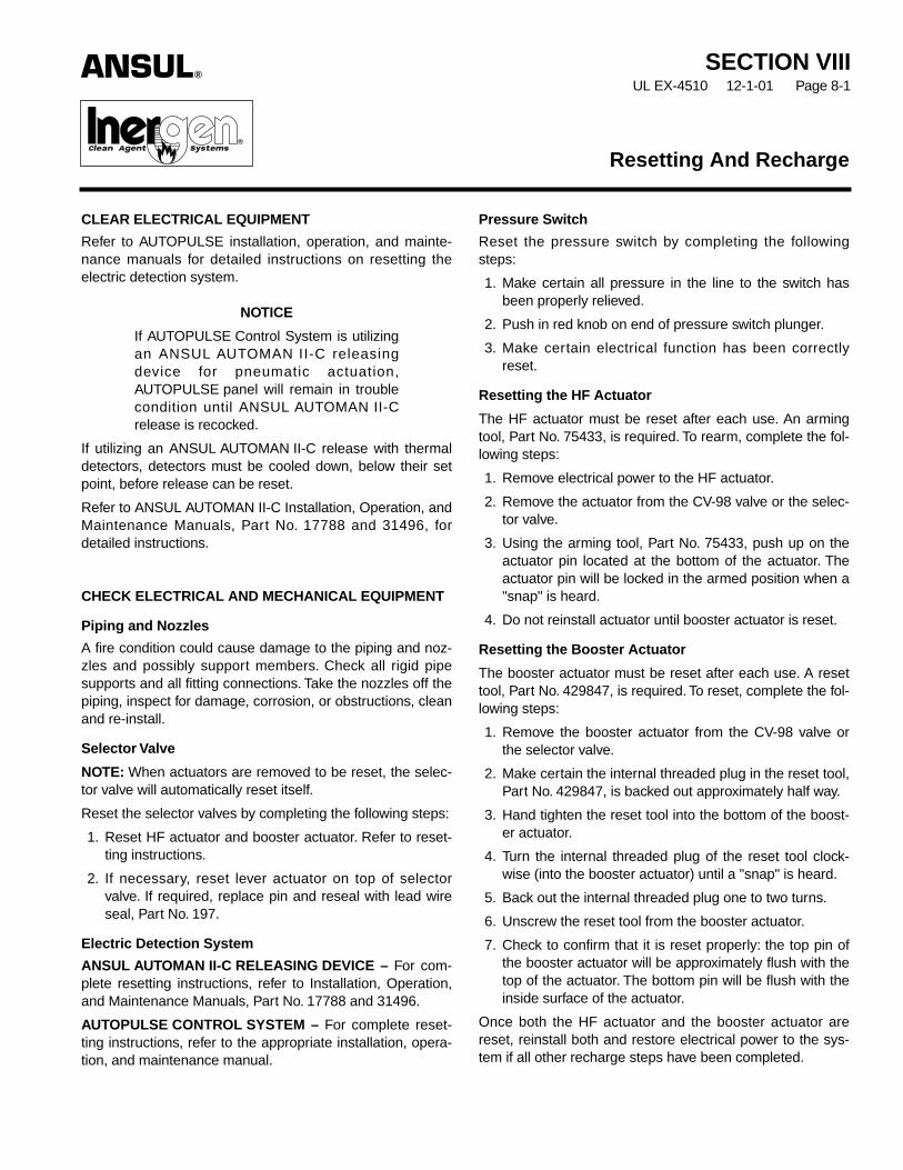
SECTION VIIIUL EX-4510 12-1-01 Page 8-1
CLEAR ELECTRICAL EQUIPMENT
Refer to AUTOPULSE installation, operation, and mainte-nance manuals for detailed instructions on resetting theelectric detection system.
NOTICE
If AUTOPULSE Control System is utilizingan ANSUL AUTOMAN II-C releasingdevice for pneumatic actuation,AUTOPULSE panel will remain in troublecondition until ANSUL AUTOMAN II-Crelease is recocked.
If utilizing an ANSUL AUTOMAN II-C release with thermaldetectors, detectors must be cooled down, below their setpoint, before release can be reset.
Refer to ANSUL AUTOMAN II-C Installation, Operation, andMaintenance Manuals, Part No. 17788 and 31496, fordetailed instructions.
CHECK ELECTRICAL AND MECHANICAL EQUIPMENT
Piping and Nozzles
A fire condition could cause damage to the piping and noz-zles and possibly support members. Check all rigid pipesupports and all fitting connections. Take the nozzles off thepiping, inspect for damage, corrosion, or obstructions, cleanand re-install.
Selector Valve
NOTE: When actuators are removed to be reset, the selec-tor valve will automatically reset itself.
Reset the selector valves by completing the following steps:
1. Reset HF actuator and booster actuator. Refer to reset-ting instructions.
2. If necessary, reset lever actuator on top of selectorvalve. If required, replace pin and reseal with lead wireseal, Part No. 197.
Electric Detection System
ANSUL AUTOMAN II-C RELEASING DEVICE – For com-plete resetting instructions, refer to Installation, Operation,and Maintenance Manuals, Part No. 17788 and 31496.
AUTOPULSE CONTROL SYSTEM – For complete reset-ting instructions, refer to the appropriate installation, opera-tion, and maintenance manual.
Pressure Switch
Reset the pressure switch by completing the followingsteps:
1. Make certain all pressure in the line to the switch hasbeen properly relieved.
2. Push in red knob on end of pressure switch plunger.
3. Make certain electrical function has been correctlyreset.
Resetting the HF Actuator
The HF actuator must be reset after each use. An armingtool, Part No. 75433, is required. To rearm, complete the fol-lowing steps:
1. Remove electrical power to the HF actuator.
2. Remove the actuator from the CV-98 valve or the selec-tor valve.
3. Using the arming tool, Part No. 75433, push up on theactuator pin located at the bottom of the actuator. Theactuator pin will be locked in the armed position when a"snap" is heard.
4. Do not reinstall actuator until booster actuator is reset.
Resetting the Booster Actuator
The booster actuator must be reset after each use. A resettool, Part No. 429847, is required. To reset, complete the fol-lowing steps:
1. Remove the booster actuator from the CV-98 valve orthe selector valve.
2. Make certain the internal threaded plug in the reset tool,Part No. 429847, is backed out approximately half way.
3. Hand tighten the reset tool into the bottom of the boost-er actuator.
4. Turn the internal threaded plug of the reset tool clock-wise (into the booster actuator) until a "snap" is heard.
5. Back out the internal threaded plug one to two turns.
6. Unscrew the reset tool from the booster actuator.
7. Check to confirm that it is reset properly: the top pin ofthe booster actuator will be approximately flush with thetop of the actuator. The bottom pin will be flush with theinside surface of the actuator.
Once both the HF actuator and the booster actuator arereset, reinstall both and restore electrical power to the sys-tem if all other recharge steps have been completed.
ANSUL®
®
Resetting And Recharge

PLACE SYSTEM BACK IN SERVICE – CV-98 VALVE
Recharge procedures for cylinder assemblies utilizing theCV-98 valve with an HF electric actuator requires normalcylinder recharging.
RECHARGE CYLINDER
The following steps must be followed when removing dis-charged cylinders from the system:
1. Disconnect the flex bend from the cylinder(s) outlet.
2. Remove all actuators from the cylinder valves.
3. If necessary, remove 1/4 in. actuation hose, elbow, andadaptor from pneumatic actuation port.
4. If necessary, install plug, Part No. 42411, into pneu-matic actuation port and wrench tighten.
5. With cylinder secured in bracket, relieve any remainingpressure in the cylinder by completing the following:
a. Make certain discharge cap IS NOT on valve outlet.See Figure 1.
FIGURE 1001515
b. Attach bleed down device, Part No. 426028, to valvefill inlet. See Figure 2.
FIGURE 2001853
c. Bleed residue pressure from cylinder. Make certaincylinder is completely empty before removing bleeddown device.
d. With cylinder completely empty, remove bleed downdevice and install safety shipping cap.
e. Complete Steps a. through d. on all dischargedcylinders, both pilot and slave.
6. Determine if discharged cylinder requires hydro-testingprior to being recharged. Note last hydro date on cylin-der collar. If cylinder does not have a star stamp, itrequires hydro 5 years from last hydro date. If cylinderhas a star stamp, it requires a hydro-test 10 years fromlast date.
NOTICE
Empty cylinders must be sent to anauthorized Ansul recharge facility forfilling. Contact Ansul Technical ServicesDepartment for any information neededconcerning authorized fillers.
SECTION VIIIUL EX-4510 7-15-02 Page 8-2
REV. 1
Resetting And Recharge
CAUTION!
Attach bleed down device, Part No. 426028, to fillinlet of discharged cylinders only. Never attach thisdevice to fully charged cylinders as this will causehigh pressure to discharge out of the fill inlet. Also,install device hand tight only. Do not wrench tighten.NOTE: Bleed-down device, Part No. 416656, CAN-NOT be used on CV-98 valve.
DISCHARGE OUTLETCAP MUST NOT BEINSTALLED WHILEBLEEDING DOWNCYLINDER
PIN IN BLEED DOWN DEVICEWILL DEPRESS CHECKVALVE IN FILL INLET

SECTION VIIIUL EX-4510 12-1-01 Page 8-3
Resetting And Recharge
After the cylinder(s) has been secured back in the bracketand discharge hose(s) have been reconnected (if neces-sary, reconnect 1/4 in. actuator hose to ball check port) andwrench tightened, attach the actuator(s) by completing thefollowing:
1. Make certain HF and booster actuators have beenreset.
2. Attach both booster and HF actuators to top thread ofCV-98 valve. Securely tighten.
MANUAL VALVE ACTUATOR
Before installing manual actuator back onto cylinder valve,make certain manual actuator is in the “SET” position. Onmanual actuator with ring pins, make certain ring pin is inposition and secured with a visual inspection seal.
If the CV-98 manual actuator was used, apply a smallamount of lubricant, such as WD-40, to the pin between thehandle and the body.
RESETTING SELECTOR VALVE
Reset HF actuator and booster actuator by following thereset instructions in this section.
NOTE: When actuators are removed to be reset, the selec-tor valve will automatically reset itself.
MANUAL PULL STATION
Reset remote manual pull station by completing the follow-ing steps:
1. If necessary, remove set screw that is retaining thebreak glass rod.
2. If necessary, carefully remove any remaining brokenglass from station.
3. Press and position handle in proper location againstcover and slide the replacement glass break rod, PartNo. 4834, through stud and handle.
4. Tighten set screw into stud.
REPLACE ANSUL AUTOMAN II-C CARTRIDGE
Install new LT-30-R nitrogen cartridge by completing the fol-lowing steps:
1. Remove shipping cap and weigh replacement cartridge.Replace if weight is 1/2 ounce (14.2 g), or more, belowweight stamped on cartridge.
2. Make certain release mechanism is cocked and lock pinis installed. Then, install replacement cartridge intorelease assembly and hand tighten.
3. Remove lock pin.
4. Secure cover on ANSUL AUTOMAN II-C release andseal with visual inspection seal.
5. Record recharge date on tag attached to unit and/or ina permanent file.
NOTIFY OWNER
1. Notify owner and/or authority having jurisdiction that thesystem has been recharged and placed back in service.
CAUTION!
Make certain all electric power from the panel to theactuator has been disconnected. Failure to disconnectpower may cause system to accidentally discharge.
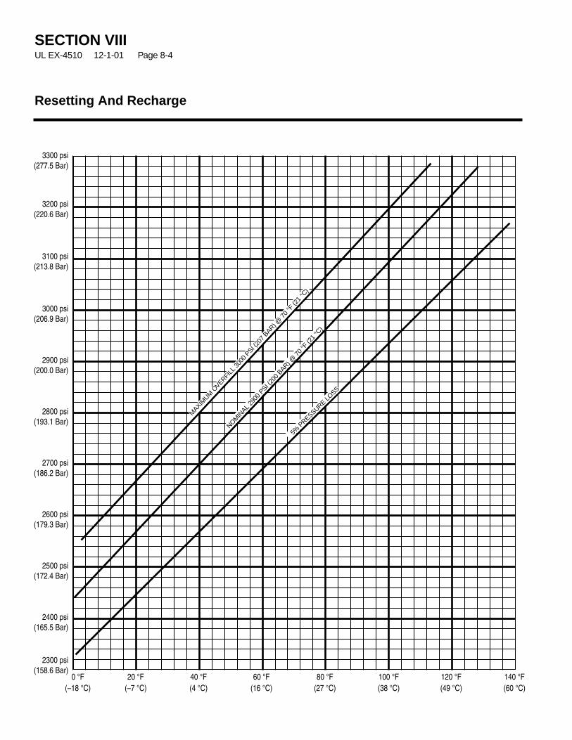
SECTION VIIIUL EX-4510 12-1-01 Page 8-4
Resetting And Recharge
3300 psi(277.5 Bar)
3200 psi(220.6 Bar)
3100 psi(213.8 Bar)
3000 psi(206.9 Bar)
2900 psi(200.0 Bar)
2800 psi(193.1 Bar)
2700 psi(186.2 Bar)
2600 psi(179.3 Bar)
2500 psi(172.4 Bar)
2400 psi(165.5 Bar)
2300 psi(158.6 Bar)
0 °F 20 °F 40 °F 60 °F 80 °F 100 °F 120 °F 140 °F(–18 °C) (–7 °C) (4 °C) (16 °C) (27 °C) (38 °C) (49 °C) (60 °C)
MAXIM
UMOVERFI
LL 3
000
PSI (20
7 BAR) @
70
°F (2
1 °C
)
NOMIN
AL29
00 P
SI (20
0 BAR) @
70
°F (2
1 °C
)
5% P
RESSURELO
SS
SECTION IXUL EX-4510 12-1-01 Page 9-1
Inspection is a “quick check” that a system is operable. It isintended to give reasonable assurance that the system isfully charged and will operate. This is done by seeing thatthe system has not been tampered with and there is noobvious physical damage, or condition, to prevent opera-tion. The value of an inspection lies in the frequency, andthoroughness, with which it is conducted. Systems shouldbe inspected at regular monthly intervals, or at more fre-quent intervals when circumstances require.
The following visual checks should be performed during anINERGEN system inspection:
– Visually inspect the hazard area to verify that it has notchanged. Look for different fuels, new equipment,blocked open doors or dampers.
– Check detectors to make certain they are in place, notdamaged or coated with dirt, grease, paint, or any conta-minating substance.
– Check all manual pull stations to assure they have notbeen tampered with and are not blocked from use.
– Check all alarm devices for damage, dirt, corrosion, etc.
– Check that the piping is secure and nozzles are in place.Make certain the nozzles are not covered with dirt,grease, or paint and that there is nothing structural block-ing the discharge.
– Visually inspect all components for signs of damage,such as disconnected or loose parts, corrosion, twisted ordented components, etc.
– Check each INERGEN cylinder indicator (gauge) todetermine that the cylinder pressure is in the operablerange.
– Verify that all pressure switches are in place and are inthe correct, nonoperated, position.
– Visually verify that control panel and/or releasing deviceis functioning properly.
– Perform any other checks that may be required by theauthority having jurisdiction.
– Verify that the pressure reducer/union contains an orificeplate by visually noting the presence of the orifice indica-tor tab on the side of the union.
– If applicable, push green poppet valve near solenoid onselector valve to relieve any pressure.
– Visually check solenoid or electric actuator wiring onselector valve to make certain it has not been disconnect-ed.
– Make certain lever actuator on selector valve is in “SET”position.
– Record that the system has been inspected and informthe proper personnel.
Inspection
ANSUL®
®�
ANNUAL MAINTENANCE EXAMINATION
General
Systems shall be maintained at regular intervals, not morethan one year apart, or when specifically indicated by aninspection. (Exception: Cylinder pressure must bechecked every six months per NFPA 2001.) Maintenanceis a “thorough check” of the system. It is intended to givemaximum assurance that a system will operate effectivelyand safely. It includes a thorough examination and any nec-essary repair, recharge, or replacement. It will reveal if thereis a need for hydrostatic testing of the cylinder. The proce-dures listed in this section are the minimum that is neces-sary to maintain a system. If circumstances warrant them, amore thorough procedure should be followed to assure sys-tem performance. Make certain that all people affected bythe maintenance are informed before you start. This mayinclude the owner, security personnel, the local FireDepartment, and possibly local workers that may be affect-ed by equipment shutdown or start up.
NOTICE
If the system includes an ANSULAUTOMAN II-C releasing device, beforeproceeding with annual maintenanceexamination, insert lock pin in ANSULAUTOMAN II-C release and remove nitro-gen cartridge. Install safety shipping capon cartridge.
1. Survey the hazard to make certain it has not changedfrom what the system was designed to protect. Whilesurveying the hazard, look for different fuels, loss ofhazard integrity, new hazards, etc.
2. Check all nozzles to make certain they are in place, thatthe orifice plates are in place and with the proper orifice.Check the condition of the nozzle for corrosion or dam-age and make certain it is not obstructed internally orexternally.
3. Check the condition of the piping to make certain that itis properly secured in the hangers and that all fittingsare connected tightly.
4. Check all warning nameplates throughout the area.Make certain they are in place, mounted securely, read-able, and are not damaged.
5. Check all cylinder bracketing. Make certain all cylindersare secured in the brackets. Check for corrosion, dam-age, or missing components.
6. Check the condition of all cylinders. Look for signs ofdamage or corrosion, and check the cylinders lasthydrotest date. (NFPA 2001 states “Cylinders continu-ously in service without discharging shall be given acomplete external visual inspection every five years ormore frequently if required. The visual inspection shallbe in accordance with Compressed Gas AssociationPamphlet C-6, Section 3; except that the cylinders neednot be emptied or stamped while under pressure.”)
Using the Pressure Test Gauge Assembly (Part No.427953 for CV-98 valves), check each cylinder to deter-mine if pressure is within the acceptable range. SeePressure Correction Chart in the Appendix Section.
To use the pressure test gauge assembly, first makecertain cylinder is properly bracketed. Before attachingassembly, make certain stem is completely backed outby turning hand wheel counterclockwise until it stops.Attach the assembly to the fi l l inlet por t of theINERGEN cylinder valve. Wrench tighten. To read thecylinder pressure, turn handwheel completely clockwiseuntil it stops, then back it off 1/4 turn. This will open thefill port. After pressure has been read, close fill port byturning handwheel completely counterclockwise. Slowlyloosen the adaptor nut to remove the pressure testgauge assembly from the fill port. While removing this,you may hear a small hiss of pressure remaining in theassembly. This is normal and will not last long. You willalso notice the gauge pressure will drop to zero.
Record the cylinder pressure for reference on the nextpressure test.
Visually note the location of the indicator needle on thecylinder valve to determine if it is in close proximity tothe actual reading of the test gauge.
7. Check condition of all cylinder discharge hoses. Lookfor signs of structural problems like abrasions or weath-er checking. Make certain all hoses are connected prop-erly. All hoses must be tested every 5 years. Refer toNFPA 2001 for detailed testing requirements.
SECTION XUL EX-4510 12-1-01 Page 10-1
Maintenance
ANSUL®
®

ANNUAL MAINTENANCE EXAMINATION (Continued)
General (Continued)
8. Check condition of all actuators by completing the fol-lowing:
a. Remove all actuators from the cylinders and leavethem off until the final step in the MaintenanceSection.
b. For manual actuators, check the condition of eachactuator to make certain they operate freely. Whenfinished, reset them and seal with inspection sealsas required. Do not install on cylinder valves.
c. For electric actuators, check to make certain allwires are properly connected. Do not install on cylin-der valves.
9. Check the condition of the orifice union and make cer-tain correct size orifice plate is in place. Orifice size canbe read on exposed tab.
10. Check all pressure switches for signs of damage or cor-rosion. Make certain piping to switch is properlyattached.
11. Check all switches on the system to assure they willoperate properly. These may include maintenanceswitches, abort switches, main/reserve switches, etc.When completed, make certain they are all set in thecorrect position.
NOTICE
Before proceeding with Step No. 12, makecertain all electrical actuators have beenremoved from all cylinder valves and thatthe cartridge has been removed from theANSUL AUTOMAN II-C releasingdevice(s) if part of the system.
12. Check condition of control panel for tampering, corro-sion, or damage. Test panel at this point by referring tothe appropriate AUTOPULSE Control System Manual.
13. Check all detectors. Make certain they are in place,clean, and not damaged. If required, check the sensitiv-ity of each per the instructions of the detector manufac-turer. See appropriate AUTOPULSE Control SystemManual for detailed operating instructions of the panel.
14. Check all pull stations. Make certain they are in place,that they are not blocked or damaged. Operate eachpull station to make certain that they operate the controlpanel. Reset each pull station and seal with visualinspection seal.
15. While checking the detectors and electric pull stations,inspect each alarm device. Check the alarms conditionand verify that it operates properly when energized.Reset the alarm circuit after each test.
16. If the system includes an ANSUL AUTOMAN II-Creleasing device, test it per the instructions titledThermal Detection/Electric ANSUL AUTOMAN II-CRelease listed in this section. If system contains a cablepull station, check it for correct operation at this time.Reset and reseal after operating.
17. Reset the entire system. This includes the controlpanel, all actuators, detectors, alarms, actuator car-tridge, release cartridge, and pressure switches. Afterall components have been reset, install actuators backon to the cylinder valves.
18. Record that the maintenance has been performed asrequired by the Authority Having Jurisdiction. Notify allpersonnel that the maintenance has been completedand the system is back to normal.
SECTION XUL EX-4510 12-1-01 Page 10-2
Maintenance
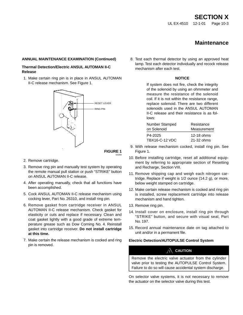
SECTION XUL EX-4510 12-1-01 Page 10-3
Maintenance
ANNUAL MAINTENANCE EXAMINATION (Continued)
Thermal Detection/Electric ANSUL AUTOMAN II-CRelease
1. Make certain ring pin is in place in ANSUL AUTOMANII-C release mechanism. See Figure 1.
FIGURE 1001894
2. Remove cartridge.
3. Remove ring pin and manually test system by operatingthe remote manual pull station or push “STRIKE” buttonon ANSUL AUTOMAN II-C release.
4. After operating manually, check that all functions havebeen accomplished.
5. Cock ANSUL AUTOMAN II-C release mechanism usingcocking lever, Part No. 26310, and install ring pin.
6. Remove gasket from cartridge receiver in ANSULAUTOMAN II-C release mechanism. Check gasket forelasticity or cuts and replace if necessary. Clean andcoat gasket lightly with a good grade of extreme tem-perature grease such as Dow Corning No. 4. Reinstallgasket into cartridge receiver. Do not install cartridgeat this time.
7. Make certain the release mechanism is cocked and ringpin is removed.
8. Test each thermal detector by using an approved heatlamp. Test each detector individually and recock releasemechanism after each test.
NOTICE
If system does not fire, check the integrityof the solenoid by using an ohmmeter andmeasure the resistance of the solenoidcoil. If it is not within the resistance range,replace solenoid. There are two differentsolenoids used in the ANSUL AUTOMANII-C release and their resistance is as fol-lows:
Number Stamped Resistanceon Solenoid Measurement
P4-2025 12-18 ohmsTBX16-C-12 VDC 21-32 ohms
9. With release mechanism cocked, install ring pin. SeeFigure 1.
10. Before installing cartridge, reset all additional equip-ment by referring to appropriate section of Resettingand Recharge, Section VIII.
11. Remove shipping cap and weigh each nitrogen car-tridge. Replace if weight is 1/2 ounce (14.2 g), or more,below weight stamped on cartridge.
12. Make certain release mechanism is cocked and ring pinis installed, screw replacement cartridge into releasemechanism and hand tighten.
13. Remove ring pin.
14. Install cover on enclosure, install ring pin through“STRIKE” button, and secure with visual seal, PartNo. 197.
15. Record annual maintenance date on tag attached tounit and/or in a permanent file.
Electric Detection/AUTOPULSE Control System
On selector valve systems, it is not necessary to removethe actuator on the selector valve during this test.
RESET LEVER
RING PIN
CAUTION!
Remove the electric valve actuator from the cylindervalve prior to testing the AUTOPULSE Control System.Failure to do so will cause accidental system discharge.

Electric Detection/AUTOPULSE Control System(Continued)
Perform system annual maintenance by following theinstructions listed in the appropriate AUTOPULSE ControlSystem Installation, Operation, and Maintenance Manual.
To test the operation of the valve actuator, apply power tothe circuit the actuator is installed on. When power isapplied, a “click” will be heard. This will confirm the actuatoris functioning.
Also, check the actuator on the selector valve. The “click”should also be heard, confirming the actuator is operating.
When all tests have been completed, make certain all con-trol panels are returned to the normal condition and thevalve actuator(s) have been correctly reinstalled back onthe cylinder valve.
SECTION XUL EX-4510 12-1-01 Page 10-4
Maintenance

Electronic data processing involves storage, recall and useof information via electronic equipment. Electronic data pro-cessing equipment is found in almost every industry today.The equipment is very sensitive and operates within minutetolerances. Additionally, many computer installations aredesigned with a subfloor area containing data and powercable bundles.
Because of the high dollar valve of the equipment, the datamanaged by that equipment and the productivity providedby electronic data processing, rapid detection and efficientfire protection are imperative. Time lost to cleanup and ven-tilation of a computer room means lost time throughout thecompany, so these areas require a clean, no residue gasagent that disperses easily.
The computer room and subfloor space can be protectedwith an INERGEN suppression system, even when thecomputer room is normally occupied.
Fires can occur within the computer electrical insulation andin the cable bundles in the subfloor. Paper debris that hasbeen allowed to accumulate in the subfloor is also a sourcefor ignition.
Computer room/subfloor protection can be accomplished byinstallation of a total f lood INERGEN system. TheINERGEN system is designed in accordance with the Ansuldesign, installation manual and NFPA Standard 2001,“Standard for Clean Agent Fire Extinguishing Systems,”which states, “the design concentration must be achievedwithin 1 minute. It is important that an effective agent con-centration not only be achieved, but shall be maintained fora sufficient period of time to allow effective emergencyaction by trained personnel.”
The INERGEN system consists of a cylinder bank, a pipingarrangement and discharge nozzles located in the roomand subfloor space.
Occasionally, drainage is installed in the subfloor area.Provisions must be made for making the drain piping aclosed system unless water is present to assist in assuringthe necessary concentration.
When the computer room is normally occupied, personnelsafety is of first concern. Alarms or warning devices mustbe located in the room to provide sufficient annunciation ofINERGEN agent discharge. The room and subfloor must betight to prevent loss of INERGEN agent.
All air handling equipment must be shut down anddampered prior to system discharge.
Smoke detectors, operated by an electronic control panel,are usually employed with an INERGEN system to providedetection and thus suppression of a fire before it has achance to do serious damage.
Thermal detectors are used as a backup automatic system.
The authority having jurisdiction may have additionalrequirements.
HAZARD
A computer room having dimensions of 20 ft. x 13 ft. x 10 ft.
A subfloor having dimensions of 20 ft. x 13 ft. x 1 ft.
No unclosable openings.
Ventilation to be shut down at system actuation.
No. 1 – Sketch of Hazard. Do an accurate sketch of thehazard area and record all dimensions and solid objects.
No. 2 – Preliminary Drawing – Complete a draft sketch ofthe piping layout to determine pipe lengths and number offittings. Locate and number all node points, manifold desig-nators, and nozzles.
No. 3 – Pipe Input Section – Complete the Pipe InputSection (tab) of the INERGEN Designer Program. Oncecompleted, print out the pipe input results.
No. 4 – INERGEN Flow Calculation – Perform theINERGEN Flow Calculation and print out the Flow Reportand the Nozzle Performance Report from the INERGENDesigner Program.
No. 5 – Review Design Concentration and Discharge Time– Return to the Design Section (tab) of the INERGENDesigner Program and review the design concentration anddischarge time for each hazard area to verify system perfor-mance. Also, at this point, verify that the piping used in thedown stream piping is acceptable for the pressures identi-fied as maximum down stream pressure on theINERGEN Designer Flow Report.
SECTION XIUL EX-4510 7-15-02 Page 11-1
REV. 1
ANSUL®
® Example – Computer Room and Subfloor

SECTION XIUL EX-4510 12-1-01 Page 11-2
Typical Applications
002203
13 FT.
10 FT.
20 FT.
2 FT.
2 FT.
2.5 FT.
1 FT.
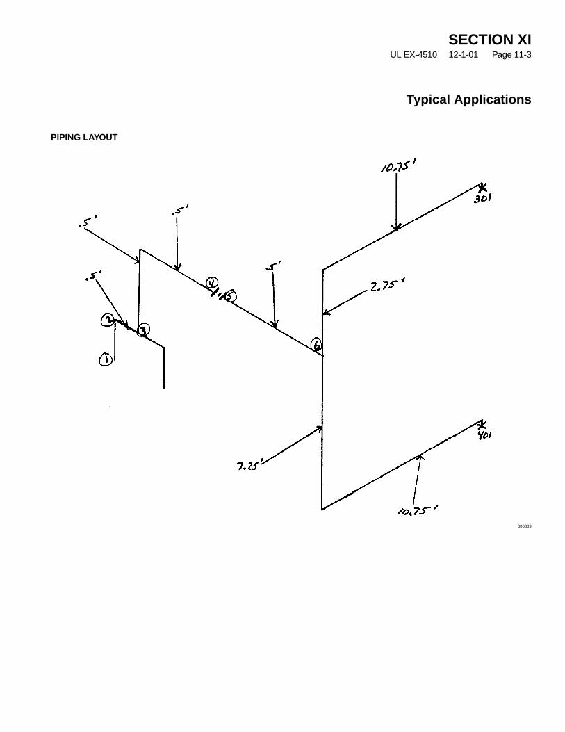
SECTION XIUL EX-4510 12-1-01 Page 11-3
Typical Applications
PIPING LAYOUT
006089
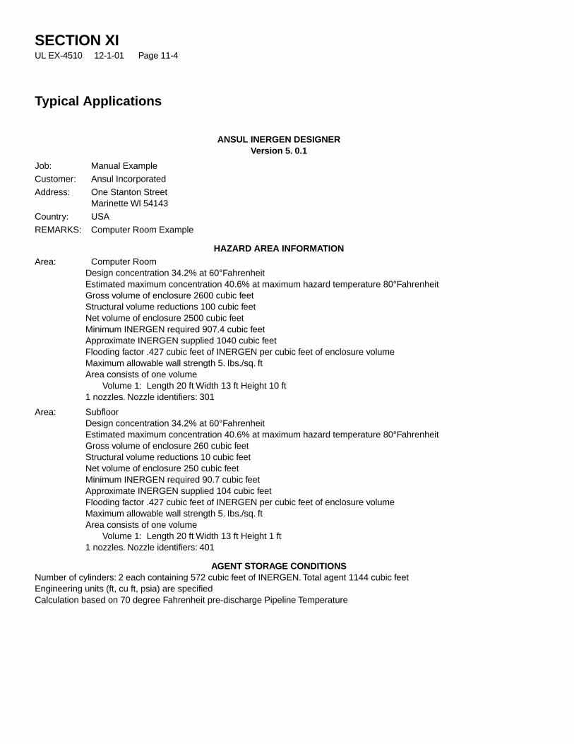
SECTION XIUL EX-4510 12-1-01 Page 11-4
Typical Applications
ANSUL INERGEN DESIGNERVersion 5. 0.1
Job: Manual Example
Customer: Ansul Incorporated
Address: One Stanton StreetMarinette Wl 54143
Country: USA
REMARKS: Computer Room Example
HAZARD AREA INFORMATIONArea: Computer Room
Design concentration 34.2% at 60°FahrenheitEstimated maximum concentration 40.6% at maximum hazard temperature 80°FahrenheitGross volume of enclosure 2600 cubic feetStructural volume reductions 100 cubic feetNet volume of enclosure 2500 cubic feetMinimum INERGEN required 907.4 cubic feetApproximate INERGEN supplied 1040 cubic feetFlooding factor .427 cubic feet of INERGEN per cubic feet of enclosure volumeMaximum allowable wall strength 5. Ibs./sq. ftArea consists of one volume
Volume 1: Length 20 ft Width 13 ft Height 10 ft1 nozzles. Nozzle identifiers: 301
Area: SubfloorDesign concentration 34.2% at 60°FahrenheitEstimated maximum concentration 40.6% at maximum hazard temperature 80°FahrenheitGross volume of enclosure 260 cubic feetStructural volume reductions 10 cubic feetNet volume of enclosure 250 cubic feetMinimum INERGEN required 90.7 cubic feetApproximate INERGEN supplied 104 cubic feetFlooding factor .427 cubic feet of INERGEN per cubic feet of enclosure volumeMaximum allowable wall strength 5. Ibs./sq. ftArea consists of one volume
Volume 1: Length 20 ft Width 13 ft Height 1 ft1 nozzles. Nozzle identifiers: 401
AGENT STORAGE CONDITIONSNumber of cylinders: 2 each containing 572 cubic feet of INERGEN. Total agent 1144 cubic feetEngineering units (ft, cu ft, psia) are specifiedCalculation based on 70 degree Fahrenheit pre-discharge Pipeline Temperature

SECTION XIUL EX-4510 12-1-01 Page 11-5
Typical Applications
ANSUL INERGEN DESIGNERUL listed EX4510. ULC listed CEx1151
Version 5.0.1
Job Number: Manual Example
PIPE DATA INPUT
Sec Sec Nominal Length Elev 90’s Side Thru Union/ Qty EqlStart End Pipe Size (ft) (ft) Tee Tee Cpig cu ft (ft)____ ____ ________ ______ ____ ____ ____ ____ ______ ____ ___
1 2 1/2 - 40 T 0.01 0.00 0 0 0 0 38.002 3 0-DFLT 0.50 0.00 1 0 0 0 0.003 4 0-DFLT 1.00 0.50 1 1 0 0 2cyl 0.004 5 0 - DFLT 0.00 0.00 0 0 0 0 Orifice5 6 0-DFLT 5.00 0.00 0 0 0 0 0.006 301 0 - DFLT 13.50 2.80 2 1 0 0 1040.00 0.006 401 0 - DFLT 18.00 -7.30 2 1 0 0 104.00 0.00
(End of Data Input File Printout)
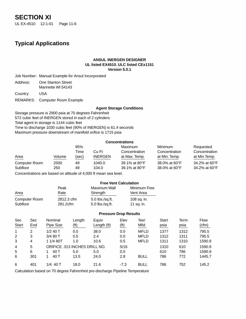
SECTION XIUL EX-4510 12-1-01 Page 11-6
Typical Applications
ANSUL INERGEN DESIGNERUL listed EX4510. ULC listed CEx1151
Version 5.0.1
Job Number: Manual Example for Ansul Incorporated
Address: One Stanton StreetMarinette Wl 54143
Country: USA
REMARKS: Computer Room Example
Agent Storage ConditionsStorage pressure is 2900 psia at 70 degrees Fahrenheit572 cubic feet of INERGEN stored in each of 2 cylindersTotal agent in storage is 1144 cubic feetTime to discharge 1030 cubic feet (90% of INERGEN) is 61.4 secondsMaximum pressure downstream of manifold orifice is 1715 psia
Concentrations95% Maximum Minimum RequestedTime Cu Ft Concentration Concentration Concentration
Area Volume (sec) INERGEN at Max. Temp. at Min. Temp. at Min Temp.____ ______ ____ ________ ___________ __________ __________
Computer Room 2500 49 1040.0 39.1% at 80°F 38.0% at 60°F 34.2% at 60°FSubfloor 250 49 104.0 39.1% at 80°F 38.0% at 60°F 34.2% at 60°F
Concentrations are based on altitude of 4,000 ft mean sea level.
Free Vent CalculationPeak Maximum Wall Minimum Free
Area Rate Strength Vent Area____ ____ ____________ ____________
Computer Room 2812.3 cfm 5.0 Ibs./sq.ft. 108 sq. in.Subfloor 281.2cfm 5.0 lbs./sq.ft. 11 sq. in.
Pressure Drop Results
Sec Sec Nominal Length Equiv Elev Tee/ Start Term FlowStart End Pipe Size (ft) Length (ft) (ft) Mfid psia psia (cfm)____ ___ ________ ______ ________ ___ ____ ____ ____ _____
1 2 1/2 40 T 0.0 38.0 0.0 MFLD 1377 1312 795.52 3 3/4 80 T 0.5 2.4 0.0 MFLD 1312 1311 795.53 4 1 1/4 80T 1.0 10.6 0.5 MFLD 1311 1310 1590.9
4 5 ORIFICE .313 INCHES DRILL NO. 5/16 1310 610 1590.95 6 1 40 T 5.0 5.0 0.0 610 786 1590.96 301 1 40 T 13.5 24.0 2.8 BULL 786 772 1445.7
6 401 1/4 40 T 18.0 21.6 -7.3 BULL 786 752 145.2
Calculation based on 70 degree Fahrenheit pre-discharge Pipeline Temperature
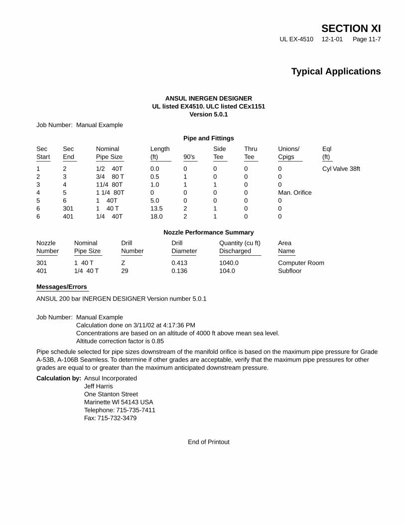
SECTION XIUL EX-4510 12-1-01 Page 11-7
Typical Applications
ANSUL INERGEN DESIGNERUL listed EX4510. ULC listed CEx1151
Version 5.0.1
Job Number: Manual Example
Pipe and Fittings
Sec Sec Nominal Length Side Thru Unions/ EqlStart End Pipe Size (ft) 90’s Tee Tee Cpigs (ft)____ ____ ________ ______ ____ ____ ____ _______ ___
1 2 1/2 40T 0.0 0 0 0 0 Cyl Valve 38ft2 3 3/4 80 T 0.5 1 0 0 03 4 11/4 80T 1.0 1 1 0 04 5 1 1/4 80T 0 0 0 0 Man. Orifice5 6 1 40T 5.0 0 0 0 06 301 1 40 T 13.5 2 1 0 06 401 1/4 40T 18.0 2 1 0 0
Nozzle Performance Summary
Nozzle Nominal Drill Drill Quantity (cu ft) AreaNumber Pipe Size Number Diameter Discharged Name______ ________ ______ _______ ____________ _____
301 1 40 T Z 0.413 1040.0 Computer Room401 1/4 40 T 29 0.136 104.0 Subfloor
Messages/Errors_______________
ANSUL 200 bar INERGEN DESIGNER Version number 5.0.1
Job Number: Manual ExampleCalculation done on 3/11/02 at 4:17:36 PMConcentrations are based on an altitude of 4000 ft above mean sea level.Altitude correction factor is 0.85
Pipe schedule selected for pipe sizes downstream of the manifold orifice is based on the maximum pipe pressure for GradeA-53B, A-106B Seamless. To determine if other grades are acceptable, verify that the maximum pipe pressures for othergrades are equal to or greater than the maximum anticipated downstream pressure.
Calculation by: Ansul IncorporatedJeff HarrisOne Stanton StreetMarinette Wl 54143 USATelephone: 715-735-7411Fax: 715-732-3479
End of Printout

ANSUL INCORPORATEDONE STANTON STREETMARINETTE, WI 54143-2542
Par
t N
o. 4
3014
9-01
©20
02 A
nsul
Inc
orpo
rate
dLi
tho
in U
.S.A
.