annual report 2014 - sccer hae · receive financial support until 2016 with a perspective of a...
TRANSCRIPT

Annual Report 2014

Imprint
SCCER HaE-Storage – Annual Activity Report 2014
Published by
Swiss Competence Center for Energy Research – Heat and Electricity Storage
Concept by
Thomas J. Schmidt, Urs Elber
Technical Review
Thomas J. Schmidt, Jörg Roth
Editorial work, design and layout by
Peter Lutz, lutzdocu.ch, Uster
Ursula Ludgate
Printed by
Paul Scherrer Institut, Villigen
Available from
Swiss Competence Center for Energy Research Heat and Electricity Storage (SCCER HaE-Storage) c/o Paul Scherrer Institute 5232 Villigen PSI, Switzerland
Phone: +41 56 310 5396 E-Mail: [email protected] Internet: www.sccer-hae.ch
Copying is welcomed, provided the source is acknowledged and an archive copy is sent to SCCER HaE-Storage.
© SCCER HaE-Storage, 2015

1
Table of Contents
Editorial
3 SCCER Networked Research – a Base for Success
Batteries – Advanced Batteries and Battery Materials
5 First-Principles Crystal Structure and Property Prediction of Com-pounds for Electrode Applications
7 Bulk Analysis of Sn-Electrodes in Sodium Ion Batteries9 Tin/Carbon Composite Anode Material for Lithium Ion Batteries and
Polyanionic Cathode Material for Sodium Ion Batteries
Heat – Thermal Energy Storage
13 High-Temperature Sensible TES Based on a Packed Bed of Pebbles17 Low-Temperature Latent TES with Encapsulated PCM21 Thermo-Mechanical Characterization of Cellular Ceramics in High-
Temperature Environments24 High-Temperature Combined Sensible/Latent-Heat Thermal Storage25 Phase Change Material Systems for High Temperature Heat Storage27 Aqueous Sodium Hydroxide Seasonal Thermal Energy Storage:
Reaction Zone Design and Optimization
Hydrogen – Production and Storage
31 Sustainable Electrocatalysts for Hydrogen Production Using Renew-able Energy
33 Demonstration of a Redox Flow Battery to Generate Hydrogen from Surplus Renewable Energy
35 Solvation Studies of Formic Acid in Water and in Organic Solvents for Mechanistic Investigations of Formic Acid Formation and Decomposi-tion
38 Hydrogen Storage in Hydrides
Synthetic Fuels – Development of Advanced Catalysists
41 New Catalysts for the Transformation of CO2 into Fuels42 Molecular Control and Understanding of Surface Chemistry44 Electrochemical CO2 Reduction46 Towards a Mechanistic Understanding of the Electro-Reduction of CO2
Integration – Interactions of Storage Systems
49 A Uniform Techno-Economic and Environmental Assessment for Electrical and Thermal Storage in Switzerland: Development and Case Studies
52 Storages for Flexibility of Power and Heat54 Applied Power-to-Gas Systems55 Performance, Lifetime, Safety and Reliability of Battery Systems

2
Appendix
59 Conferences61 Presentations63 Publications
Table of Contents

3 Editorial
SCCER Networked Research – a Base for Success
The Swiss Competence Center for Energy Research (SCCER) «Heat and Electricity Storage» (HaE) is one of eight centers, which have been established in the research fields of mobility (SCCER Mobility), efficiency (SCCER FEEB+D, SCCER EIP), power supply (SCCER SoE), grids (SCCER FURIES), biomass (SCCER Biosweet), energy storage (SCCER HaE) , as well as economy and environment (SCCER CREST) in light of the Swiss Government’s Energy Strategy 2050.
The declared aim of this energy strategy is the transition from nuclear power to a power supply system based on renewable sources to meet the CO2 emission targets. An important factor is to expand and strengthen the knowledge in the energy field through the increase of personnel resources, e.g., scientists, en-gineers, technicians alongside with technology development. The centers are organized as virtual consortia of industrial and aca-
demic institutions (cantonal universities, universities of applied sciences and federal universities and research centers) distributed all across Switzerland with the intension to maximize the outcome by combining the strongest competencies in each area of expertise.
To maintain a long-lasting effect on the Swiss power supply system, the competence centers will receive financial support until 2016 with a perspective of a second period until 2020.
Energy storage is a key element in this venture since energy, sourced from renewables like wind and solar energy, is only available on an intermittent, stochastic basis. Storing excess energy in times of low energy demand and releasing it in times of high energy demand is not only useful from an energetic perspective, it also may create an economic value within the energy market.
With an increasing contribution of the aforementioned renewable energy sources to the electricity mix, the significance of energy storage increases. This is clearly demonstrated by countries hav-ing installed a lot of wind and photovoltaic power, e.g., Germany and Denmark. Large intermittent discrepancies between electricity production and demand are being observed with the consequence of strongly fluctuating electricity prizes, causing also challenges to the stability of the power supply system.
In order to stabilize the grid, an increase in short term electricity storage capacity (hrs) with high response time is needed within the next years. In the long run, seasonal storage becomes important to ensure constant electricity supply without conventional fossil based power generation.
Heat, aside from electricity, is one of the most required type of energy today. About 50 % of the primary energy carriers are transformed to heat by modern industrialized societies – required for space heating, hot water and process heat. Thus, it becomes obvious that a sensible use of energy must not neglect the questions related to heat.
The research and development within the SCCER Heat and Electricity Storage concentrates on five different fields with the involvement of more than 20 research groups from eleven public institutions as well as from the private sector.
With this «Annual Report 2014», we would like to invite you to learn more about the different areas of research and development carried out in the SCCER Heat & Electricity Storage within its first year of operation.
Prof. Dr. Thomas J. Schmidt Head SCCER Heat and Electricity Storage
List of abbreviations
SCCER Swiss Competence Center for Energy Research

BatteriesAdvanced Batteries and Battery Materials
Illu
stra
tion
: to
loko
nov
/ iS
tock

5 Batteries
Illu
stra
tion
: to
loko
nov
/ iS
tock
First-Principles Crystal Structure and Property Prediction of Compounds for Electrode Applications
Authors
Riccarda Caputo¹ Maksym V. Kovalenko¹
¹ ETHZ
Scope of project
Designing new materials with specific properties implies a detailed understanding of their structure and electronic properties at atomic level. Quite often structure and exact composition of compounds are extremely difficult to determine precisely from the experiments. The prediction of the possible crystal structures at different compositions represents indeed the very basic knowledge for any fur-ther electronic structure property investigation.
Status of project and main scientific results of workgroups
• elemental antimony with the trigonal symmetry space group, Sb(r),
• binary phases containing iron, FeSn2, FeF3, FeS2.
A-Sn and A-Sb are the typi-cal examples of the electrical potential as a function of the composition across the binary phase diagrams. The A-FeXn
systems are examples of in-tercalation followed by terna-
List of abbreviations
F Fluorine
Fe Iron
Li Lithium
Na Sodium
S Sulfur
Sb Antimony
Sn Tin
TM Transition Metals
either unknown or not-yet determined experimentally, localized on the energy-com-position curve of the A(Li, Na)-host phase space, are checked for the lattice stability via pho-non calculations.
The host systems investigated, as potential electrode materi-als, are: • elemental tin, • tetragonal phase Sn(t),
Figure 1:
The calculated XRD pat-terns of NaxSn, modelled via discharge of Na in Sn(t).
Figure 2:
The calculated potential of lithiation (left) and so-diation (right) of Sb(r) as a function of composition (x).
By employing a first-principle methodology, which couples cluster expansion, random searching and simulated an-nealing algorithms with total energy calculations at Den-sity Functional Theory level [1, 2], Li- and Na-containing compounds relevant for bat-tery applications were studied. The electrochemical discharge/charge processes of ions (Li, Na) at the electrodes is stud-ied as a variable composition problem of the type atom (Li, Na)-host, during which the lat-tice of the host compounds un-dergoes to structural changes at different degrees. In fact, the energy-composition and the energy-volume curves, derived from total energy cal-culations and geometry op-timization of the modelled compounds, are important for understanding how much the discharge/charge reactions can be reversible.
The predicted local minima and global minima structures,

6 Batteries
First-Principles Crystal Structure and Property Prediction of Compounds for Electrode Applications
ry phase formation and then phase decomposition.
Sn(t) and Sb(r) were inves-tigated as anode for A-ion batteries (A stands for alkali metal element, in the follow-ing Li and Na). The theoreti-cal specific charges are 847.7 mAhg-1 and 660.4 mAhg-1, re-spectively, upon full discharge leading to the formation of Na15Sn4 and Li3Sb (Na3Sb). The first-principles crystal struc-ture prediction can serve as a complementary and important tool for predicting possible structures and understanding the structure-composition re-lationships, as reported in the running joint work with PSI lab on the Na-Sn system.
In fact, and this is of general validity, the discharge/charge processes in the electrochemi-cal cell can visit not only the thermodynamic states of the phase space of the Na-Sn sys-tem but also pass through local minima and accordingly show the formation of unknown phases. The calculated ener-gy-composition relationship of NaxSn, for x in (0, 3.75), sug-gested that the first steps of sodiation are endothermic, for x ≤ 0.063, followed by a pla-teau-like region, for 1 < x < 2, and then by a step down to the final state for x = 3.75, leading to the formation of Na15Sn4. In terms of the calculated poten-tial, the discharge reaction oc-curs at 0.25 volts for 1 < x < 2 and 0.143 volts for x = 3.75 [3].
The Li-Sb and Na-Sb phase diagrams report the formation of two compounds each: • Li2Sb and Li3Sb; • NaSb and Na3Sb.
The structural differences of AxSb, for x < 3 between Li- and Na-antimonides is reflected into the discharge/charge re-actions. In fact, while in the Na-Sb system there exists a global minimum energy state at x = 1, in Li-Sb the lithia-tion using Sb as cathode read-ily leads to the formation of Li3Sb passing through the lo-cal minima state at x = 2. The calculated average poten-tial of the discharge reaction xLi + Sb → LixSb for 1 < x < 3 is in the range (0.82, 0.93) volts down to 1.01 volts at x = 3.
The calculated discharge po-tentials leading to the forma-tion of the hexagonal structures Li2Sb and Li3Sb are very close: 1.00 V and 1.01 V, respec-tively [4-5]. Differently, the calculated average potential of sodiation of antimony falls in the range (0.44, 0.52) volts for 1 < x < 3 and is 0.62 volts for the formation of Na3Sb(h) [6]. Interestingly, the energy-volume curves of the two sys-tems, Li-Sb and Na-Sb, as a function of the composition, show that while in Li-Sb the cell volume doubles at the final point, x = 3, in Na-Sb the cell volume of Na3Sb(h) is almost four times that of elemental Sb(r) and a larger hysteresis is found along the structure-composition curve [6].
Among the iron-based cath-ode materials, FeF3, the tri-gonal phase, was investigated for the lithiation process. Two phases have been found for LixFeF3, x = 0.5 and x = 1. The calculated potentials are 0.89 volts and 2.91 volts, respec-tively, to discharge 0.5 and 1 mole of lithium in FeF3(t) [7]. The other two iron-based com-pounds, FeSn2 and FeS2, are
still under study in order to investigate the phase space of the ternary systems A-FeX2, and then extend the study to other convenient transition metals (TM) forming (di)-stan-nides, sulphides, and fluorides of type A-TMX2.
References
[1] R. Caputo, RSC Advances, 3, 10230–10241 (2013).
[2] G. Zeng et al., Chem. Mater., 25, 3399–3407 (2013).
[3] L.O. Vogt et al., PSI Annual Report 2014.
[4] R. Caputo, talks at 3rd TYC Energy Materials Workshop, Sept. 2014, London and MSE 2014, Darmstadt.
[5] R. Caputo, in prepara-tion.
[6] R. Caputo, submitted.
[7] R. Caputo, in prepara-tion.

7 Batteries
Bulk Analysis of Sn-Electrodes in Sodium Ion Batteries
Authors
Leonie O. Vogt¹ Petr Novák¹ Claire Villevieille¹
¹ PSI
Scope of project
The high demand for advanced energy storage systems has resulted in increased research into novel battery systems. Na-ion batteries are a promising candidate for large-scale energy storage due to the abundance and low cost of Na. As Na is also an alkali metal, the electrochemistry and basic principles of Na-ion batteries are analogous to the well-known Li-ion batteries.
List of abbreviations
Cl Chlorine
FEC Fluoroethylene Carbonate
ICSD Inorganic Crystal-lographic Structure Database
Li Lithium
Na Sodium
O Oxygen
OCV Open Circuit Volt-age
P Phosphorus
PC Propylene Carbon-ate
Sb Antimony
Sn Tin
SEI Solid Electrolyte Interphase
XRD X-ray Powder Dif-fraction
Status of project and main scientific results of workgroups
Experimental
XRD measurements were performed with a PANalyti-cal Empyrean diffractometer using Cu Kα radiation. A self-standing electrode was used in the setup composed of 70 wt% Sn, 20 wt% PVDF binder and 10 wt% Super-P carbon. The electrode was cast from an ac-etone suspension onto Teflon film and then dried in air. It was cycled against sodium metal at a C/30 rate in the electrolyte NaClO4 in PC + 5% FEC; 250 μL of electrolyte were used to soak the glass fibre separator in the cell.
Results
The phase diagram of Na-Sn reports nine possible binary phases, of which one, NaSn, can be found in two differ-ent polymorphs. The in situ XRD patterns of the sodiation process are shown in Figure 1 (left). The crystalline phase of the tetragonal Sn is clearly visible at open circuit volt-age (OCV). As the sodiation proceeded, new phases were formed. In the Sn-rich region, for x < 1, none of the phas-es reported in the Inorganic Crystallographic Structure Database (ICSD), NaSn5 and NaSn2, matched the scanned diffraction patterns (Figure 1, middle), thus an unknown phase is seen. As regimes are shifted from the tin rich to the
sodium rich phases (> 1 Na per Sn atom) the unknown phase disappears and is re-placed by NaSn phase reached after Na1.125–Na1.25. This extra 0.25 sodium can be at-tributed to the solid electro-lyte interphase (SEI) forma-tion identified around 0.55 V. The NaSn phase rapidly shows amorphization as the sodiation proceeds (i.e., Na1 → Na2.5) and new peaks appear. As with the first intermediate phase formed these new peaks be-long to an unknown phase. They could not be matched to the thermodynamically stable phase Na9Sn4 (Figure 1, right).
As sodiation progresses an interesting feature becomes visible during the second and third sodiation steps. Care-ful examination of the peak at 19.07° reveals an increasing intensity around x = 2, a maxi-mum around x = 2.5, and then a decreasing intensity and shift to lower angles at x = 3, where the final phase Na15Sn4 is formed. In literature an ad-ditional phase Na29.58Sn8 which crystallizes in an orthorhombic system has been mentioned, however we didn’t identify this phase in our experiments.
Conclusion and out-look
The Na-Sn system has been studied via in situ XRD mea-surements during the cycling
It was recently reported that commercially available ele-ments such as P, Sb and Sn react electrochemically with three or more Na ions per for-mula unit through conversion reactions [1-3]. For anode ma-terials specific charge of above 500 mAh/g for over 100 cycles has been demonstrated [4].
Sn, in particular, is a promising anode material with a specific charge of above 800 mAh/g upon full sodiation, resulting in the formation of Na15Sn4. Understanding the reaction mechanism of sodiation/de-sodiation processes is crucial for further development of Sn and related composites as high energy density anode materi-als in Na-ion batteries. In the present work the bulk reaction mechanism of the sodiation of a Sn anode was investigated by using in situ X-ray Powder Diffraction (XRD) and first-principles crystal structure prediction methodologies.

8 Batteries
Bulk Analysis of Sn-Electrodes in Sodium Ion Batteries
of high energy density Sn electrodes in sodium ion bat-teries. The material undergoes a range of phase transitions. Three known phases as well as two unknown phases have been observed. The determi-nation of the reaction mecha-nism of Sn with Na is a crucial step to be able to understand and further develop this prom-ising anode material and its derivatives.
References
[1] Y. Kim et al., Adv. Mat., 25 (22), 3045–3049 (2013).
[2] J.F. Qian et al., Chem. Comm., 48 (56), 7070–7072 (2012).
[3] Y. Xu et al., Adv. En. Mat., 3 (1), 128–133 (2013).
[4] A. Darwiche et al., J. Am. Chem. Soc., 134 (51), 20805–20811 (2012).
[5] R. Caputo et al., RSC Adv., 3 (26), 10230–10233 (2013).
Figure 1:
Left – In situ XRD of the first sodiation of Sn elec-trodes.
Middle – In situ XRD cor-responding to NaSn2 with three references from the ICSD.
Right – In situ XRD cor-responding to Na9Sn4 with two references from the ICSD.

9 Batteries
Tin/Carbon Composite Anode Material for Lithium Ion Batteries and Polyanionic Cathode Material for Sodium Ion Batteries
Authors
Katharina M. Fromm¹ Nam Hee Kwon¹ Sivarajakumar Maharajan¹
¹ University of Fribourg
Scope of project
This is a collaborative project between the group of Prof. H.-G. Park from ETHZ and Prof. K.M. Fromm from the University of Fribourg, dedicated to study the Li-air batteries.
List of abbreviations
Co Cobalt
Fe Iron
Li Lithium
Mn Manganese
Na Sodium
O Oxygen
P Phosphorus
Sb Antimony
Si Silicon
Sn Tin
TEM Transmission Elec-tron Microscopy
Ti Titanium
XRD X-ray Powder Dif-fraction
Status of project and main scientific results of workgroups
During the first year of this SCCER, members of this work group were busy in project ac-quisition for 3rd party funding, which was successful for an NRP-70 project of the SNSF, which started on October 1st 2014. A PhD student has been hired at University of Fribourg as of December 1st 2015 for the synthesis of new electro-lytes. Given the late start of this PhD student, no results have so far been obtained for this part of the project. How-ever, S. Maharajan started to work on February 1st 2014 and contributed to the research in-teractions within WP 1.
Sn/C composite anode material for Li-ion bat-teries
The current commercial anode material, graphite, has a low energy density (375 mAh/g-1) and safety problems due to lithium deposition [1]. Al-loy anodes (LixSn or LixSi) are found to be interesting in terms of high energy-density, enhanced safety and long cy-cle life. The theoretical specific capacities of alloy anodes are 2–10 times higher than that of graphite and 4–20 times high-er than that of lithium titanium oxide (Li4Ti5O12). The alloy an-odes are safer than graphite anodes due to the high reactiv-ity of graphite which has much lower standard reduction po-tential. However, the moderate operation voltage (0.3 – 0.4 V vs. Li+/Li) is much lower than
that of lithium titanate anodes (1.5V vs. Li/Li+) [2]. In es-sence, these alloy based an-odes are eligible candidates in terms of high energy density and safety. However, the main hurdle faced in commercializ-ing these alloy anodes is the huge volume variation (up to
300 %) during lithium insertion and extraction, which leads to the rupture of the active al-loy particles and poor cycling, caused by the poor electrical contact [3].
In order to overcome the poor contact in the electrode due to the pulverization following volume expansion, we apply a yolk-shell structure using a carbon shell and Sn nanoparti-cles as yolks. The carbon shell will prevent the aggregation of Sn and has good electronic conductivity. In addition, cre-ating a void inside the carbon shell will accommodate the volume change of Sn nanopar-ticles upon Li-insertion. A reverse micelle approach is known to yield yolk-shell type metal nanoparticles inside SiO2 shells [4] as shown in Figure 1. In analogy, we obtained Sn
nanoparticles in a SiO2 shell (Sn@SiO2 yolk-shell, Figure 2, left). Afterwards, the yolk-shell particles were covered with an organic coating, lead-ing to carbonization via a heat treatment to obtain the car-bon-coated Sn@SiO2 particles (Figure 2, right). The etching
of the SiO2 layer and a ther-mal treatment will provide the formation of Sn-encapsulated hollow carbon with void in near future.
Polyanionic cathode material for Na-ion batteries
The source of lithium may be limited to apply in the au-tomotive market. Thus, us-ing sodium instead of lithium for rechargeable batteries is considered as an alternative high-energy battery. Polyanion (PO4
3-, P2O74-) based cathode
materials (NaMPO4, M = Mn, Fe, Co) for sodium ion bat-teries are good candidates on grounds of cycle stability, ther-mal stability, safety, environ-mental friendliness and cost [5]. NaMnPO4 exists in both ol-ivine and maricite phases with
Figure 1:
A schematic view of the formation of Sn/C compos-ite with void.

10 Batteries
the former being preferable in terms of Na ion conductivity and the low temperature for-mation while the latter is ther-modynamically stable at high-er temperatures [6]. Also the maricite phase has a blocked structural arrangement, which hinders the pathway of Na+ ions. Consequently, the mar-icite phase is electrochemi-cally inactive. Therefore, an effective synthesis method is needed now to synthesize oliv-ine NaMnPO4 at the nanometer scale.
The polyol synthesis was used, a precipitation method to syn-thesize NaMnPO4 nanoparticles in a high-T° boiling organic medium [7]. However, after the synthesis, the maricite phase was obtained, which is not the desirable phase for Na
ion insertion/extraction. Fig-ure 3 shows the XRD pattern and TEM image obtained af-ter the polyol synthesis. When heated, the synthesized ma-terial retained the phase until 600 °C, but new peaks appear above 900 °C. The nature of this material is being investi-gated.
In order to obtain the desired olivine phase of NaMnPO4, ol-ivine-LiMnPO4 was synthesized via the polyol method [7]. Then, lithium will be removed by electrochemical techniques. As a next step, it is planned to make electrochemical sodia-tion of MnPO4 to obtain olivine NaMnPO4.
References
[1] M. Winter et al., Advanced Materials, 10, 725–763 (1998).
[2] W.-J. Zhang, J. of Power Sources, 196, 13–24 (2011).
[3] M. Winter et al., Electrochimica Acta, 45, 31–50 (1999).
[4] M. Priebe et al., Part. Part. Syst. Char., 31, 645–651 (2014).
[5] Z. Gong and Y. Yang, Energy Environ. Sci., 4, 3223–3242. (2011)
[6] J. Moring et al., J. Solid State Chem., 61, 379–383 (1986).
[7] D. Wang, et al., J. of Power Sources, 189, 624–628 (2009).
Figure 2:
TEM images of Sn@SiO2 (left) and carbon coated on SiO2 shell (right).
Figure 3:
XRD pattern (left) and TEM image (right) of maricite NaMnPO4.
Tin/Carbon Composite Anode Material for Lithium Ion Batteries and Polyanionic Cathode Material for Sodium Ion Batteries

11

HeatThermal Energy Storage
Illu
stra
tion
: Atr
opat
/ iS
tock

13 Heat
Illu
stra
tion
: Atr
opat
/ iS
tock
High-Temperature Sensible TES Based on a Packed Bed of Pebbles
Authors
Simone Zavattoni¹ Antonio Gaetano¹ Jonathan Roncolato¹ Marco Fossati¹ Maurizio Barbato¹ Alberto Ortona¹
¹ SUPSI
Scope of project
The integration of high-temperature thermal energy storage (TES) systems into concentrating solar power (CSP) plants, besides being a valuable solution to economically compete against solar pho-tovoltaics (PV), allows to make solar energy dispatchable, increasing substantially its value to the grid. According to the TES systems in operation, sensible heat is by far the most exploited solution for storing thermal energy. Packed beds of gravel, as low-cost filler material, are a valuable and reliable option to sensibly reduce the cost of the storage system. Furthermore, this solution may found a large applicability in the case the CSP plant uses air as heat transfer fluid (HTF). Being a single-tank solution, the buoyancy-driven effects of the HTF are exploited to establish and maintain a thermocline zone which separates the hot region on top and the cold region at the bottom of the tank. The thinner the thermocline, the higher the thermodynamic quality of the stored energy, i.e. higher exergy content. However, the extent of thermal stratification may vary sharply during cycles especially during start-up when the TES is charged for the first time.
Status of project and main scientific results of workgroups
List of abbreviations
CFD Computational Fluid Dynamics
CSP Concentrated Solar Power
DNI Direct Normal Ir-radiance
ETC Effective Thermal Conductivity
FVM Finite Volume Method
HE Heat Exchanger
HTF Heat Transfer Fluid
PV Photovoltaics
TES Thermal Energy Storage
UDF User Defined Func-tion
Computational fluid dynamics (CFD) is a useful tool which al-lows, during the design phase, to analyze the thermo-fluid dynamics behaviour of the TES system focusing on the optimi-zation of its thermal stratifica-tion capability. In the present work, an industrial-scale rock bed TES system has been ana-lyzed by means of accurate 3D CFD simulations with the aim of evaluating the transient evolution of thermal stratifi-cation into the packed bed. A total of 30 consecutive cycles, constituted by 12 hours of charging followed by 12 hours of discharging, were simulated computing, for all of them, a stratification efficiency index based upon the second law of thermodynamics.
Industrial-scale TES system
The single-tank TES system under investigation was de-signed to fulfil the round-the-clock energy requirement of a reference 80 MWe CSP plant which uses air as HTF. The lat-ter is fed through the storage at 650°C; whereas, after the power block heat exchangers
(HEs), the HTF temperature is reduced down to 270 °C. On the basis of the reference oper-ating temperatures, a packed bed of natural rocks, 3–4 cm average particles diameter, was exploited as low-cost filler material. The pebbles are con-tained into a concrete vessel, buried into the ground, with a truncated-cone shape in order to minimize the effect of ther-mal ratcheting on the lateral walls.
During the charge phase, the HTF at high temperature flows downward through the packed bed delivering its thermal en-ergy to the gravel. Conversely, during the discharge phase, the energy stored can be re-covered by reversing the air-flow direction with the HTF coming from the heat exchang-ers of the power block. Hence, 650 °C and 270 °C were as-sumed as reference charging and discharging temperatures respectively. With the given CSP plant dimensions, and considering the case of largest available DNI (in the month of June), calculations showed that a total of 7 TES units, 25.7 m and 21.7 m the upper and the
lower diameter respectively and 9.5 m packed bed height, are required to hold the whole volume of about 30,000 m3 of rocks [1]. The thermal capac-ity of each TES unit, defined as the total energy stored in the packed bed when charged from ambient temperature to isothermal conditions at the inlet air flow temperature of 650 °C, is about 1 GWhth. The air mass flow rate through each TES unit is about 89.6 kg/sec for both the charging and discharging.
With the aim of obtaining a proper velocity distribution of the HTF through the packed bed, as similar as possible to a plug flow, each TES unit was equipped with four pipes on top, and four pipes at the bot-tom respectively, rather than a single pipe located in the centre. Furthermore, two calm chambers were also designed on top and at the bottom of the packed bed.
CFD model
Continuity, Navier-Stokes, en-ergy, turbulent kinetic energy and turbulent dissipation rate

14 Heat
High-Temperature Sensible TES Based on a Packed Bed of Pebbles
transport equations were nu-merically solved with the finite volume method (FVM) ap-proach [2] by means of Flu-ent 14.5 code from ANSYS. The left-hand side of figure 1 shows the CAD model of one of the seven units. The com-putational domain considered for the analysis is a quarter of the whole geometry. It was discretized with a grid of al-most 1,150,000 hexahedral elements. The right-hand side of figure 1 shows the compu-tational domain with the main boundary conditions applied to the numerical model.
Thermal energy losses by means of conduction through the ground and convection/ra-diation from the lid towards the external environment were ac-counted for. The environment temperature was assumed equal to 35 °C and 20 °C dur-ing the charge phase and the discharge phase respectively.
The layers of concrete and in-sulating materials, constitut-ing the containing vessel, were numerically modelled with a single material of equivalent thermo-physical properties. At the beginning of the time-dependent CFD simulation, i.e. at time t = 0 sec, the TES sys-tem unit was considered in its dead state, i.e. thermal equi-librium with its environment.
The dead-state temperature was assumed to be 17 °C.
The rock-bed was treated as a continuum and hence it was modelled exploiting the po-rous media approach [3]. An effective thermal conductivity (ETC), based upon the Kunii & Smith’s model [4][5], was con-sidered to account for all the non-convective heat transfer mechanisms occurring into the packed bed. The ETC was im-plemented into the CFD code by means of a purpose-built user defined function (UDF), i.e. a «C» routine properly written to be linked to the CFD solver. Thermal radiation heat transfer was accounted for by the ETC itself and hence none radiation model was activated for the computation. A qua-dratic void-fraction distribution was also implemented in order to replicate the different parti-cles arrangement, numerically and experimentally observed [6, 7] in the axial direction of the packed bed.
Air was treated as incompress-ible ideal gas with tempera-ture-dependent thermo-phys-ical properties assigned as piecewise linear interpolations of tabulated data. Conversely, the thermal properties of the solid materials (rocks and con-cretes) were experimentally measured and extrapolated
afterwards, to cover a wider temperature range [7]. The extrapolated values were then assigned to the relative mate-rials as piecewise linear pro-files.
Results and discussion
The CFD simulations results are presented in terms of temperature distribution at different time spans. Non-di-mensional quantities were ex-ploited to describe the results obtained; non-dimensional po-sition and temperature of unity indicate the upper surface, and the highest temperature re-spectively, of the packed bed.
Figure 2 shows the result ob-tained in terms of temperature distribution into the packed bed as a function of the axial position. The left-hand side of figure 2 focuses on the tem-perature distribution at the end of some of all the charge phases analyzed; instead, the right-hand side of figure 2 de-picts the end of the relative discharge phases. As clearly visible from the graphs, dur-ing the initial cycles, the TES undergoes a sharp variation of thermal stratification. This is due to the fact that, at the be-ginning of the CFD simulation, the TES system was assumed to be in its dead-state; the ef-fect of having both the charg-
Figure 1:
Schematic CAD model of the TES system (left) and relative boundary condi-tions (right).

15 Heat
ing and discharging tempera-tures different from that of the initialization led to the creation of two separate thermocline zones into the packed bed.
From a graphical standpoint, figure 3 shows the temperature contours of the TES system at the end of several consecu-tive charge phases. An impor-tant consideration that can be drawn, looking at the result obtained, is that about 28–30 cycles are required by the sys-tem before achieving a stable thermal stratification into the packed bed. Considering that a single cycle corresponds to one day, the transient behaviour of the TES system is in the order of one month. Pre-charging the TES system, i.e. charging the storage for a certain time before the beginning of the cyclic operation, might be a valuable solution to reduce the long time required to achieve a stable condition.
Thermocline TES – thermal stratification
For thermocline TES, thermal stratification is among the key parameters to maximize the overall efficiency of the sys-tem: the thinner the thermo-cline, the higher the thermo-dynamic quality of the stored energy, i.e. higher exergy con-tent. Exergy is a measure of the work potential of a given amount of energy or, in other words, the maximum amount of energy that can be extract-ed from the system, at the specified state, as useful work.
Thanks to the advantage of being directly applicable in conjunction with a CFD-based analysis, the stratification ef-ficiency, given by the so-called
entropy generation ratio [8], was exploited to evaluate the transient evolution of thermal stratification into the industri-al-scale TES unit. The qualita-tive information obtainable by using this second-law based approach is the extent to which the real TES system under in-vestigation approaches the ideal case of perfectly stratified TES, i.e. zero-thickness of the
thermocline zone with the two regions into the packed bed, at high and low temperature, adi-abatically separated. Stratifi-cation efficiency close to unity indicates that the real TES is operating with a sharp thermal stratification, i.e. the entropy generation is minimized, and the thermal energy is stored at the highest thermodynam-ics quality.
Figure 2: Non-dimensional tempera-ture as a function of non-dimensional packed bed height at the end of some charge (left) and discharge (right) phases.
Figure 3:
Temperature contours of the TES system at the end of several consecutive charge phases. Tempera-ture values are [°C].
High-Temperature Sensible TES Based on a Packed Bed of Pebbles

16 Heat
Evaluation of stratifi-cation efficiency
With the aim of characterizing the stratification efficiency of the industrial-scale TES sys-tem proposed, a UDF was de-veloped and implemented into Fluent. Once executed, the UDF allows to perform a loop over all the computational cells of the packed bed in order to collect information such as temperature, volume and ab-solute position of each cell.
Based upon an arbitrary num-ber of divisions, the packed bed is virtually divided in the axial direction into a multilayer zone of constant thickness. All the cells information are auto-matically stored into the prop-er layer according to the axial position of each cell. The tem-perature of each layer is then computed by means of a vol-ume-averaging technique. The resulting array, containing the temperature and the volume of each layer, is automatically exported and post-processed.
The gathered values were ex-ploited to compute the total amount of energy and exergy available into the packed bed along with the entropy change of the TES during the process.
Results obtained
The methodology to qualita-tively evaluate the stratifica-tion efficiency was applied to the 30 consecutive cycles analyzed. The result obtained in terms of transient evolution of thermal stratification is re-ported in figure 4. The markers represent the average value of the stratification efficiency of all the phases analyzed. To ob-tain these average values, six instantaneous stratification ef-ficiency indexes were comput-ed for each phase correspond-ing to an interval of about two simulation hours between one instant of time and the follow-ing.
The highest value of stratifica-tion efficiency, of about 0.93 on average, was achieved dur-ing the first charge indicating that the thermal stratification of the TES system is com-parable to the ideal case of perfectly stratified TES. The stratification efficiency sensi-bly decreases down to 0.58, on average, already for the con-secutive discharge phase indi-cating an entropy generation increment given by the cre-ation of the two thermocline zones into the packed bed. A minimum value of stratification
efficiency can be observed, for both the charge and discharge phases, between the 5th–6th cycle.
The difference between the average stratification effi-ciency of the charge and dis-charge phases reduces with consecutive cycles, disappear-ing towards the 19th–20th cycle wherein a maximum is also achieved and the two thermo-cline zones merge with each other into a single one. From this point forward, the strati-fication efficiency slightly de-creases until reaching a stable condition of about 0.65.
Conclusions
The 3D CFD simulation results of the TES system, analyzed under 30 consecutive cycles of charging and discharging, were exploited to observe the effect of the initial cycles on thermal stratification. The lat-ter, qualitatively evaluated with a second-law based fig-ure of merit, showed a strong variation lasting for 20–22 cycles. A stable thermal strati-fication into the packed bed was achieved towards the end of the 30 cycles analyzed. The long transient behaviour is the result of the two ther-mocline zones, observed into the packed bed for the first 19–20 cycles, due to the fact the TES was considered in its dead state at the beginning of the test. Pre-charging the TES system before the first cycle might be a valuable solution to sensibly reduce the long time required to achieve a stable thermal stratification.
References
[1] S.A. Zavattoni et al., «High temperature rock-bed TES system suitable for industrial-scale CSP plant – CFD analysis under charge/discharge cyclic conditions», Energy Procedia, 46, 124–133 (2014).
[2] H.K. Versteeg et al., «An Introduction to Com-putational Fluid Dynamics: The Finite Volume Method Approach.» Harlow, Eng-land: Longman Scientific and Technical, (1995).
[3] D.A. Nield et al., «Convection in Porous Me-dia», Springer, (2006).
[4] S. Yagi et al., «Studies on effective thermal conductivities in packed beds», AIChE Journal, 3 (3), 373–381 (1957).
[5] D. Kunii et al., «Heat transfer character-istics of porous rocks», AIChE Journal, 6 (1), 71–78 (1960).
[6] S. A. Zavattoni et al., «CFD simulations of a peb-ble-bed Thermal Energy Storage system account-ing for porosity variations effects», 17th SolarPACES Conference, September 20–23, Granada, Spain, (2011).
[7] G. Zanganeh et al., «Packed-bed thermal stor-age for concentrated solar power – Pilot-scale dem-onstration and industrial-scale design», Solar Energy, 86, 3084–3098 (2012).
[8] V. Panthalookaran et al., «A new method of char-acterization for stratified thermal energy stores», Solar Energy, 81 (8), 1043–1054 (2007).
Figure 4:
Average transient stratifi-cation efficiency for con-secutive charge/discharge cycles.
High-Temperature Sensible TES Based on a Packed Bed of Pebbles

17 Heat
Low-Temperature Latent TES with Encapsulated PCM
Authors
Simone Zavattoni¹ Maurizio Barbato¹ Marco Fossati¹ Antonio Gaetano¹ Jonathan Roncolato¹John Doyle² Nelson Garcia Polanco² Joaquin Capablo²
¹ SUPSI² Whirlpool R&D
List of abbreviations
CFD Computational Fluid Dynamics
DSC Differential Scan-ning Calorimetry
FVM Finite Volume Method
HTF Heat Transfer Fluid
LTNE Local Thermal Non-Equilibrium
PCM Phase Change Material
TC Thermocouple
TES Thermal Energy Storage
Figure 1:
Schematic of the TES sys-tem (left) and boundary conditions applied to the model (right).
Status of project and main scientific results of workgroups
Latent TES system
The latent TES developed is composed by an insulated cy-lindrical polymeric container exploited to hold the PCM capsules (3–4 mm diameter range) constituting the packed bed (left-hand side of figure 1). The PCM selected is a paraffin, manufactured and provided by Microtek laboratories, with a nominal melting temperature of 32 °C.
During charging the wast-ed energy produced by the household appliances is har-vested and transported by the heat transfer fluid (HTF) to the TES system feeding it from top. Percolating through the packed bed, the HTF delivers its thermal energy to the cap-sules, causing hence the PCM to melt. Conversely, during discharging the flow direction of the HTF is reversed and the energy stored in the capsules can be recovered and reused. Air was exploited as HTF for
several economical and practi-cal reasons. For instance, air is already exploited by vari-ous appliances as waste heat source (i.e. electric ovens, mi-crowave ovens, refrigerators); furthermore, it is particularly suitable for the packed bed based TES system proposed.
CFD model
The TES system was analyzed by means of accurate 3D time-dependent CFD simulations with the twofold aim of evalu-ating its thermo-fluid dynam-ics behaviour and developing
a robust and reliable model to predict its performance under different working conditions.
Thanks to the symmetric char-acteristic of the TES system, only half of the whole model was assumed as computa-tional domain. It was then discretized with a grid of al-most 1,251,000 hexahedral elements. The right-hand side of figure 1 shows the compu-tational domain considered for the CFD analysis along with the main boundary conditions applied.
Scope of project
Over the last two decades, the electricity consumption of the residential sector in the European Union (EU-27) showed a remarkable 40 % increment from about 600 TWh in 1990 up to almost 843 TWh in 2010 which is, so far, the highest amount of the last century [1]. After industry, the residential sector is the second most important consumer accounting for almost 30 % of the total electricity consumption. For this reason, the efficient use of energy by domestic appliances, along with the possibility of recovering and reusing their waste heat, is becoming more and more relevant. Waste heat usually refers to the fraction of energy that is lost, in the form of heat, by industrial processes, machines, electrical and domestic equipments. Within a typical household, the potential energy savings from waste heat recovery can be up to 25 % and, since appliances do not necessar-ily operate sequentially, a proper thermal energy storage becomes essential to enable the recovery and reuse on-demand of the harvested energy [2]. Given the requirements of system integration into a kitchen environment, a latent thermal energy storage (TES) system, based on a packed bed of macro-encapsulated organic phase change material (PCM), was selected as most suitable and promising solution. In the present work, a computational fluid dynamics (CFD) based approach was exploited to evaluate the performance of the TES system under investigation. Furthermore, an experimental campaign was also conducted on a purpose-built full-scale TES prototype in order to obtain useful data for validating the CFD model developed.

18 Heat
Mass, momentum and energy conservation equations were numerically solved in transient regime with the finite volume method (FVM) approach [3] by means of Fluent 14.5 code from ANSYS. Thermal energy losses by means of convection and radiation from the external surfaces towards the environ-ment were accounted for. The polymeric container, along with the layers of insulating mate-rial, was numerically mod-elled with a single material of equivalent thermo-physical properties. The packed bed was treated as a continuum and it was modelled exploit-ing the porous media approach [4]. Local thermal non-equilib-rium (LTNE) was assumed and hence two different energy equations, for the solid and the fluid phases respectively, were solved. The so-called dual cell approach was exploited. In such an approach, a solid zone that is spatially coincident with the porous fluid zone is de-fined, and this solid zone only interacts with the fluid with re-gard to heat transfer.
As far as concerning the PCM, its phase transition was mod-elled as a sensible process, i.e. non-explicit phase change tracking with an increased material specific heat, as the phase change occurs, account-ing for its latent heat of fu-sion. This so-called effective heat capacity was defined as piecewise linear profile as a function of temperature. The specific heat of the PCM in both the solid and the liquid states, along with the latent heat of fusion, were determined ac-cording to the results of the differential scanning calorim-etry (DSC) analysis performed on purpose.
Because of the relatively low operating temperatures, ra-diative heat transfer into the computational domain was considered negligible with re-spect to other heat transfer mechanisms and thus none ra-diation model was activated for the computations.
TES prototype and ref-erence experimental test
Figure 2 shows the experimen-tal prototype that was built and tested. The PCM capsules were randomly packed into a plastic container, 0.7 m high, with a circular cross-section of 0.4 m diameter. At the bot-tom of the tank, a perforated metallic plate was exploited to sustain the packed bed pre-venting hence the risk of cap-sule leakage into the bottom duct. Hot air was provided by means of two electric heater and fan systems, connected in series with each other, po-sitioned at the top of the pro-totype. Two butterfly valves, one in the upper duct and the second in the lower duct, allow to isolate the internal region of the TES prototype simulating the idle phase of the system, i.e. none mass transfer into and out of the TES. A flow dis-tributor, positioned below the upper duct, was exploited to avoid the direct impingement of the incoming HTF on the su-perficial layer of PCM capsules leading also to a proper plug-flow through the packed bed. The internal and the external surfaces of the container re-spectively were equipped with two layers of insulating foam in order to minimize heat losses.
The TES prototype was equipped with several K-type thermocouples (TCs) with the aim of continuously monitoring and recording the temperature evolution into the system. The ambient temperature, the inlet and the outlet HTF tempera-tures were measured along with the temperature of both the internal and external sur-faces of the container to evalu-
Figure 2:
Experimental TES system prototype: overview (left); perforated metallic plate (top-right); internal insu-lating foam layer (bottom-right) [5].
Low-Temperature Latent TES with Encapsulated PCM

19 Heat
ate the heat losses. However, the majority of the TCs were positioned on layers at differ-ent heights into the packed bed: one at the centre of the layers and the others radially distributed at precise locations on a cross-like plastic frame-work.
The HTF mass flow rate was computed knowing both the HTF temperature and veloc-ity. The latter was measured by means of a hot-wire an-emometer probe (AP471 S3 DelthaOhm) with a resolution of 0.01 m/sec and an accuracy of ±0.3 m/sec. The measure-ments were taken from the bottom pipe during charging and from the upper pipe dur-ing discharging at different distances from the pipe wall in the radial direction to obtain an indicative description of the air flow velocity profile. This al-lowed to compute an average HTF velocity for a more accu-rate mass flow rate evaluation. The pressure drop through the packed bed was also mea-sured by means of differential pressure sensors (DelthOhm PP473 S1) with a resolution of 0.01 mbar. The measured data were collected, every 10 sec-onds, with a DO 2003 Del-taOhm data logger.
Among the various tests per-formed, a charge phase was selected as reference experi-mental result to validate the numerical model developed. For this reference test only a reduced fraction of capsules, approximately 16 kg or 20 cm of packed bed height, was con-sidered with the aim of reduc-ing the time required to fully charge the TES system. Fig-ure 3 shows the temperature evolution into the packed bed
during the reference test. The TCs were positioned on three layers as follows: 2 on the up-per surface of the capsules, 9 on the middle plane at 10 cm from the upper layer, and 5 at the bottom layer in contact with the metallic grid (right-hand side of figure 3).
The evolution of the inlet tem-perature, along with that of the mass flow rate, is reported in figure 4. As visible from the graph, the inlet temperature of the HTF was well beyond the design value of 37 °C in order to ensure that the complete phase change of the material takes place during the test.
A strong transient behaviour of both inlet temperature and mass flow rate was observed during the whole charge phase. Because of that and to accurately replicate the real experimental conditions, the time variation of these quan-tities was implemented into the numerical model by means of purpose-built user-defined functions.
Results and discussion
Figure 5 shows the compari-son between the experimen-tal data (red lines) and CFD simulation results (blue lines) of the central TCs on the three levels into the packed bed. The results obtained show that the numerical model reacts more slowly than the experimental prototype, probably indicat-ing an underestimation of the heat transfer coefficient into the packed bed. Conversely, the offset between the curves of the upper central TC might be due to an uncertainty of the exact TC location during the experimental test.
The left-hand side of figure 6 shows the HTF velocity magni-tude contours on the symmetry plane of the TES system. The effect of the flow distributor is well visible; the HTF in the entrance region is spread over the whole container cross-sec-tion. Only a minor fraction of mass flow rate passes through the 25 holes (1 cm diameter) in the central region of the dis-tributor. Since the majority of the HTF flows outward from the latter, the formation of two separate toroidal eddies, above and below the flow dis-tributor, can be observed in the upper fluid region. This effect is more clearly visible looking at the vectors plot reported in the right-hand side of figure 6.
Figure 7 shows the tempera-ture distribution into the TES system at different time steps. As the charge phase proceeds,
Low-Temperature Latent TES with Encapsulated PCM
Figure 3 (upper):
Temperature evolution into the packed bed during the reference experimental test with the schematic of the TCs position.
Figure 4 (middle):
Transient behaviour of inlet temperature and mass flow rate during the experimen-tal test.
Figure 5 (lower):
Transient behaviour of inlet temperature and mass flow rate during the experimen-tal test.

20 Heat
Low-Temperature Latent TES with Encapsulated PCM
the fraction of capsules above the PCM melting temperature increases. After about 1.5 hrs, half of the capsules underwent the phase change. In the sec-ond half of the test, a thermal gradient in the radial direction of the packed bed can be ob-served. This is due to the heat losses towards the external en-
vironment. An additional layer of insulation can be of help in further reducing the amount of thermal energy that is lost through the container walls. At the end of the test, almost all the capsules are above the melting point of the PCM and therefore, the TES system can be considered fully charged.
Conclusions
A latent TES system was ana-lyzed by means of transient 3D CFD simulations with the aim of evaluating its thermo-fluid dynamics behaviour under different working conditions. The numerical model was vali-dated with experimental data gathered from the purpose-built full-scale prototype.
Despite some differences be-tween CFD simulation results and experimental data, given the various assumptions and simplifications introduced, the general temperature evolution of the real prototype is fairly well described by the numeri-cal model developed.
References
[1] P. Bertoldi et al., «Energy efficiency Status Report 2012», JRC – Joint Research Centre, (2012).
[2] P. Bansal et al., «Advances in household appliances – A review.» Appl. Therm. Eng., 31, 3748–3760 (2011).
[3] H.K. Versteeg et al., «An Introduction to Com-putational Fluid Dynamics: The Finite Volume Method Approach.» Harlow, Eng-land: Longman Scientific and Technical, (1995).
[4] D.A. Nield et al., «Con-vection in Porous Media», Springer, (2006).
[5] S. A. Zavattoni et al., «Household appliances wasted heat storage by means of a packed bed TES with encapsulated PCM», 13th International Conference on Sustain-able Energy Technologies (SET), Geneva, August 25–28 (2014).
Figure 6:
Contours of velocity mag-nitude – Symmetry plane (left) and entrance region magnification (right).
Figure 7:
Temperature contours into the TES system during the charge phase at different time spans.

21 Heat
Thermo-Mechanical Characterization of Cellular Ceramics in High-Temperature Environments
Authors
Ehsan Rezaei¹Alberto Ortona²Maurizio Barbato²Sophia Haussener³
¹ SUPSI/EPFL² SUPSI³ EPFL
List of abbreviations
AE Acoustical Emission
ER Electrical Resis-tance
Status of project and main scientific results of workgroups
Scope of project
Cellular ceramics are attractive materials for high temperature applications such as thermal energy storage systems, thermal protection systems, porous burners, reformers, and volumetric solar ra-diation absorbers [1–3]. These material structures are able to withstand oxidative environments at high temperatures and are particularly resistant to thermal shock. This work presents our recent studies on thermal and mechanical behavior of Si-SiC porous ceramics including both numerical and experimental approaches.
Mechanical and ther-mal simulations
Numerical simulations showed the influence of cell morphol-ogy on thermal conductivity and mechanical properties of reticulated ceramic foams. We used tetrakaidecahedron cells to approximate the real foam structures. Effective thermal conductivity, effective elastic modulus and stress concen-tration factor were calculated using a parametric study con-sidering foams with differ-ent porosities, cell inclination angle and ligament tapering. Figure 1 shows the effect of one of these parameters (cell inclination angle) on effective elastic modulus and effective thermal conductivity.
Mechanical testing
Si-SiC open-celled foams were produced by EngiCer, Swit-zerland. A Replica technique followed by Si infiltration was used. In the case of lattice structures the polymeric tem-plate was designed using a parametric MATLAB code and then manufactured using a 3D printer. The final product was a macro-porous reticulated ce-ramic, microscopically made of reaction bonded β-SiC, α-SiC powders, Si, and a low amount of residual carbon.
Flexural tests were conducted on both random and lattice structures in order to better understand their mechanical behavior. Acoustical emission (AE) and electrical resistance (ER) were recorded during the tests to gain more informa-
tion on the fracture of indi-vidual struts in the samples, exemplarily shown in Figure 2 for a random foam of size 15 × 25 × 170 mm. Data were then processed using Weibull statistics. AE and ER moni-toring techniques show to be practical means to detect the crack initiation in these foams. An increased amount of Si in the material resulted in high-er strength, favouring Si-SiC foams, especially if passive oxidation conditions are met and therefore excess silicon oxidation is mitigated at high temperatures.
Thermal conductivity
Effective thermal conductiv-ity of lattices and foams were measured using a custom-made experimental set-up (Figure 3, left). Cubic speci-
Figure 1:
Left: Influence of cell incli-nation angle, θ, on effec-tive elastic modulus, Eeff, for different relative densi-ties, d, in a lattice made of tetrakaidecahedron cells.
Right: Influence of cell in-clination angle, θ, on effec-tive thermal conductivity Ke, for different porosities, ε, in a lattice made of tet-rakaidecahedron cells.

22 Heat
men were placed between two plates held at constant tem-peratures. The thermal con-ductivity was measured after the system reached steady state. The thermal conductiv-ity of a tetrakaidecahedron lat-tice sample (cubic with 4 cells in each edge) after oxidation in 1600 °C is displayed in figure 3 (right).
Conclusion
Si-SiC porous ceramics are special materials with unique properties that find applica-tions in very high tempera-tures (above 1000 °C).
Direct modeling of foams can be a very accurate method to predict the properties of these
Thermo-Mechanical Characterization of Cellular Ceramics in High-Temperature Environments
Figure 2:
ER (upper) and AE (lower) measurements and corre-sponding measured forces.
References
[1] A. Ortona et al., Sol. Energy Mater. Sol. Cells, 132, 123–130 (2015).
[2] S. Gianella et al., Adv. Eng. Mater., 14 (12), 1074–81 (2012).
[3] T. Fend, Optica Applicata, 40 (2), 271–284 (2010).
Figure 3:
Left: Test set-up to mea-sure effective thermal conductivity in lattices and foams.
Right: Thermal conductiv-ity of foam samples after oxidation in 1600 °C in air.
materials in different appli-cations. However due to the complex geometry of foams, a direct modeling is a very expensive and impractical ap-proach. New methods must be developed to allow for coupled thermo-mechanical character-ization.

23 Heat
High-Temperature Combined Sensible/Latent-Heat Thermal Storage
Authors
L. Geissbühler¹M. Kolman¹A. Haselbacher¹A. Steinfeld¹G. Zanganeh²
¹ ETHZ² Airlight Energy SA
List of abbreviations
AA-CAES Advanced Adia-batic Compressed Air Energy Storage
HTF Heat Transfer Fluid
PCM Phase Change Ma-terial
PHES Pumped Hydro Energy Storage
TES Thermal Energy Storage
Status of project and main scientific results of workgroups
Scope of project
Our primary interest in high-temperature thermal energy storage (TES) stems from its use in ad-vanced adiabatic compressed air energy storage (AA-CAES). In AA-CAES, electricity is used during periods of low demand to power an electric motor that drives a compressor. The thermal energy contained in the compressed air is stored, and the cooled air is stored in a sealed reservoir. To gen-erate electricity during periods of high demand, the air is released from the reservoir, absorbs heat from the storage, and is expanded through a turbine that drives a generator. With a well-designed TES, the efficiency of an AA-CAES plant is projected to reach about 75 %.
AA-CAES is of interest for two main reasons. First, it is at present the only alternative to pumped hydro energy storage (PHES) that can be competitive in terms of capacity and efficiency [1]. CAES is unique in that it is the only alternative to PHES that has been proven in practice at utility scale with the power plants in Huntorf, Germany and McIntosh, USA. The second reason why AA-CAES is of interest is cost. AA-CAES plants are estimated to be cheaper to construct and operate than PHES plants [2]. Efficient heat storage is the key enabling technology for AA-CAES and therefore the cen-tral focus of this project.
Sensible-heat TES units are often based on thermal oils or molten salts. Their disadvan-tages make them unattractive for AA-CAES.
Thermal oils are not only flam-mable and toxic, but also un-stable above temperatures of about 400 °C, far below the target compressed air tem-perature of about 550–600 °C. The high freezing points of molten salts mean that a heat-ing system must be used as a safeguard, incurring an energy penalty and complicating the power plant.
A further disadvantage com-mon to thermal oils and mol-ten salts is that their use in an AA-CAES plant requires heat exchangers, thereby reducing the overall efficiency and com-plicating the plant design.
To avoid these disadvantages, we use a packed bed of rocks as the sensible storage medi-um and air as the heat transfer fluid (HTF) [3]. Rocks are an abundant and economical stor-
age material with attractive volumetric heat capacities.
The primary disadvantage of any sensible-heat TES is that the outflow temperature of the HTF decreases dur-ing discharge. This negatively impacts the turbine in an AA-CAES plant because it is not continuously operating at its design point. One possibility of avoiding the temperature decrease is to add a limited amount of phase change mate-rial (PCM) to the sensible-heat storage, resulting in combined sensible/latent-heat storage.
Preliminary experimental re-sults with AlSi12 as the PCM, encapsulated in stainless steel tubes and placed on top of the packed bed of rocks, indicat-ed that the combined storage could indeed stabilize the out-flow temperature of the HTF [4]. More importantly, the pre-liminary experiments showed that as little as a few volume percent of PCM was sufficient to stabilize the outflow tem-perature. This result is signifi-
cant because AlSi12 is about 1200 times more expensive per unit mass than the rocks.
Over the first year of this re-search project, the primary focus has been on additional measurements with an im-proved lab-scale TES, more accurate simulations using a quasi-one-dimensional model, and a detailed comparison of the combined sensible/latent-heat and sensible-heat-only TES.
A comparison of measured and simulated temperatures at var-ious axial locations in the com-bined sensible/latent-heat lab-scale TES is shown in Figure 1 over three charge-discharge cycles. Given the simplicity of the quasi-one-dimensional representation, the agreement is good. In the right subfigure, the empty circles indicate the outflow temperature of the air, which can be seen to be nearly constant during the solidifica-tion of the PCM.
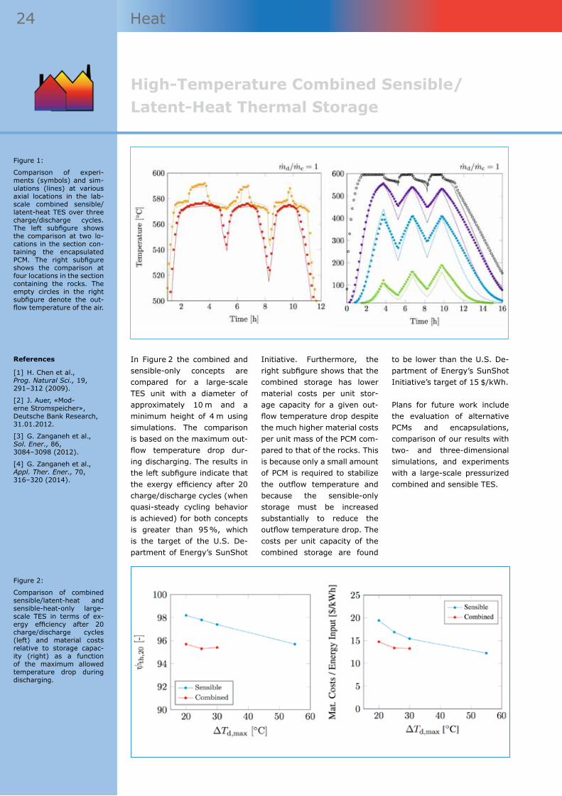
24 Heat
In Figure 2 the combined and sensible-only concepts are compared for a large-scale TES unit with a diameter of approximately 10 m and a minimum height of 4 m using simulations. The comparison is based on the maximum out-flow temperature drop dur-ing discharging. The results in the left subfigure indicate that the exergy efficiency after 20 charge/discharge cycles (when quasi-steady cycling behavior is achieved) for both concepts is greater than 95 %, which is the target of the U.S. De-partment of Energy’s SunShot
Initiative. Furthermore, the right subfigure shows that the combined storage has lower material costs per unit stor-age capacity for a given out-flow temperature drop despite the much higher material costs per unit mass of the PCM com-pared to that of the rocks. This is because only a small amount of PCM is required to stabilize the outflow temperature and because the sensible-only storage must be increased substantially to reduce the outflow temperature drop. The costs per unit capacity of the combined storage are found
to be lower than the U.S. De-partment of Energy’s SunShot Initiative’s target of 15 $/kWh.
Plans for future work include the evaluation of alternative PCMs and encapsulations, comparison of our results with two- and three-dimensional simulations, and experiments with a large-scale pressurized combined and sensible TES.
References
[1] H. Chen et al., Prog. Natural Sci., 19, 291–312 (2009).
[2] J. Auer, «Mod-erne Stromspeicher», Deutsche Bank Research, 31.01.2012.
[3] G. Zanganeh et al., Sol. Ener., 86, 3084–3098 (2012).
[4] G. Zanganeh et al., Appl. Ther. Ener., 70, 316–320 (2014).
Figure 2:
Comparison of combined sensible/latent-heat and sensible-heat-only large-scale TES in terms of ex-ergy efficiency after 20 charge/discharge cycles (left) and material costs relative to storage capac-ity (right) as a function of the maximum allowed temperature drop during discharging.
Figure 1:
Comparison of experi-ments (symbols) and sim-ulations (lines) at various axial locations in the lab-scale combined sensible/latent-heat TES over three charge/discharge cycles. The left subfigure shows the comparison at two lo-cations in the section con-taining the encapsulated PCM. The right subfigure shows the comparison at four locations in the section containing the rocks. The empty circles in the right subfigure denote the out-flow temperature of the air.
High-Temperature Combined Sensible/Latent-Heat Thermal Storage

25 Heat
Phase Change Material Systems for High Temperature Heat Storage
Authors
David Perraudin¹Sophia Haussener¹
¹ EPFL
List of abbreviations
HTF Heat Transfer Fluid
PCM Phase Change Ma-terial
Status of project and main scientific results of workgroups
Scope of project
The development of technologies for energy storage has been intensified in recent years driven by the disparity between energy availability and demand, which is expected to increase further as an increasing amount of energy is provided from renewable and intermittent sources. A large fraction of the end energy is used in heating applications, in Switzerland amounting to about 50 % of which an estimated 14 % is used in high temperature applications (temperatures > 400 °C). In order to cover this need for continuous availability of thermal energy with renewable sources or waste heat, advanced heat storage technologies are required. Latent heat storage by means of phase change materials (PCM) has proven to be an attractive heat storage technology. Key advantages include the high energy storage density, applicability to high temperatures, and the ability to store and release heat at a constant temperature.
Heat storage system
A suitable heat storage system can consist of a porous struc-ture of encapsulated PCMs, as depicted in figure 1. Dur-ing charging a heat transfer fluid (HTF) at high tempera-tures (above the melting tem-perature of the PCM) flows through the porous structure and transfers its thermal en-ergy to the PCM by convective, conductive, and radiative heat transfer. During discharging, the HTF is below the melting temperature of the PCM and heat is transferred back. The HTF is heated up to the melt-ing temperature of the PCM, thus guaranteeing a constant exit temperature of the HTF.
System modelling
A detailed model is developed which will support the choice of the PCM material, interlayer and encapsulation materials, the design of the structure, and the operating conditions for a variety of up and down-stream applications. The latent heat storage material system modelled is composed of a me-tallic PCM and a metal-ceramic PCM encapsulation. Using a metallic PCM with high materi-
al bulk conductivity compared to materials commonly used as PCMs, such as salts, auto-matically alleviates challenges connected to inefficient charg-ing and discharging. The multi-component encapsulation al-lows for robustness via the chemically inert and thermally stable ceramic layer while en-suring mechanical stability and enhanced heat transfer by the metallic layer. This model is approached by • implementing simpler 1D
codes focusing on the melt-ing/solidification, and
• more complex 3D codes fo-cusing on the coupled heat transfer (radiation, conduc-tion, convection) and fluid flow.
Eventually, these codes will be combined into a complete, transient and 3D heat storage model.
1D numerical model focusing on melting/solidification
The 1D numerical model fo-cusing on the melting/solidifi-cation is based on the solution of the Stefan problem [1] for materials with different spe-cific heats, given latent heat
and density. Time dependent boundary conditions of Dirich-let or Von Neumann type can be imposed.
Figure 2 illustrates results ob-tained for the one-dimensional setup where SiC was used as encapsulating material and copper as PCM. Figure 2 (a) illustrates the discharging phase modelled by removing a constant heat rate of 50 kW for 83 minutes, and the resulting inward movement of the solidi-fication front and decrease in temperature. Figure 2 (b) illus-trates the charging, modelled by addition of the same heat rate for the same amount of time. The melting starts from the outside with the melting front moving inwards. We ob-served the simultaneous ap-
Figure 1:
Generic latent heat storage system, (a) charging phase and (b) discharging phase.

26 Heat
pearance of two melting/so-lidification fronts, pointing to the need of a detailed under-standing of the coupled fluid flow and heat transfer for an optimal PCM material usage and heat transfer.
The numerical method used is based on liquid mass fraction and works well for the one di-mensional cases. The gener-alisation of the model into two and three dimensions adds the challenge of determining the orientation of the melting fronts. This is currently be-ing implemented for a 2D un-steady case using the volume of fluid method to simulate the evolution of the free boundar-ies [2]. This algorithm will be included in the aforementioned code applicable to 3D unsteady cases and unstructured mesh-es.
3D model focusing on coupled heat transfer and fluid flow
The 3D model for coupled heat transfer and fluid flow focuses on investigating the effects of coupled conductive, radiative, and convective heat trans-fer in combination with phase change by means of numeri-cal simulations. The numeri-cal code developed is capable of performing parallelized full 3D unsteady simulations on unstructured grids obtained from an in-house [3] and oth-er commercial mesh genera-tors. An efficient Monte Carlo (MC) ray tracing algorithm is implemented to simulate the radiative heat exchange and coupling algorithms are inves-tigated. The ray tracing algo-rithm is based on an algorithm previously used for particle tracing [4]. A fully path length based approach is chosen to obtain optimal results. Reflec-tion and refraction at phase boundaries is accounted for by splitting incoming rays into two rays with corresponding intensities.
Exemplary results are depicted in figure 3 for a simplified ge-ometry consisting of a solid phase in a non-absorbing, stagnant void phase. The dis-
tribution of the normalised absorbed radiation internally emitted from the cell high-lighted is shown. For the solid phase, properties of a ceramic material were used and for the void phase those of air. The coupling of the radiation with the conduction is achieved by iteration.
The developed code will allow to investigate different geom-etries and materials, and to assess which material combi-nations and which kind of heat exchanger setup are high per-forming candidates for several specific applications.
Additionally, the code in com-bination with advanced vol-ume averaging theory [5] will be used to determine effec-tive transport properties for the coupled problem, allow-ing for their subsequent use in continuum models of the heat storage process. Particularly, we focus on the effect of the coupled heat transfer modes, which are commonly assessed separately, but expected to be inaccurate when coupling ef-fects are strong. Leroy et al. [6] recently derived the vol-ume averaged equations for the case of coupled radiative-conductive heat transfer. Un-derstanding the coupling will contribute to the process of evaluating macroporous media as potential structures to be used as heat exchanger in the context of high temperature heat storage.
References
[1] S.C. Gupta, «The Classical Stefan Problem», Elsevier (2003).
[2] C.W. Hirt et al., J. Comput. Phys., 39 (1), 201–255 (1981).
[3] H. Friess et al., Int. J. Numer. Methods Eng., 93 (10), 1040–1056 (2013).
[4] A. Haselbacher et al., J. Comput. Phys., 225 (2), 2198–2213 (2007).
[5] S. Whitaker, «The Method of Volume Averaging», Kluwer Aca-demic Publishers (1999).
[6] V. Leroy et al., Transp. Porous Media, 98 (2), 323–347 (2013).
Phase Change Material Systems for High Temperature Heat Storage
Figure 2:
Discharging and charging of a simplified, 1D latent heat storage system.
Figure 3:
Normalized absorbed ra-diation inter-nally emitted from the cell highlighted.

27 Heat
Aqueous Sodium Hydroxide Seasonal Thermal Energy Storage: Reaction Zone Design and Optimization
Authors
Xavier Daguenet-Frick¹Paul Gantenbein¹Matthias Rommel¹
¹ HSR
List of abbreviations
A/D Absorber/Desorber
E/C Evaporator/Con-denser
Status of project and main scientific results of workgroups
Scope of project
In a previous project at Empa (2002 to 2010) experience was gained in the handling/treatment of sodium lye and in the corrosion behaviour of sodium lye containing components and tanks. The horizontal plate (dish) heat and mass transfer components – applied in this project – did not show the expected effect of heat release in the absorption process step. This and the assumption of some available data as well as the ambitious COMTES (COMpact Thermal Energy Storage) proposal led to the identification of the concept of falling film absorption and desorption as a promising technology to be applied in the storage development.
With the concept of separating the power (the reaction zone – absorption/desorption and evapora-tion/condensation) and the capacity (storage of sorbent and sorbent in individual tanks) a power and capacity scaling can be done separately. The merger of the seasonally shifted process steps absorption (winter) and desorption (summer) in one falling film unit and the process steps evapo-ration (winter) and condensation (summer) in a second falling film unit is reducing the volume of the system and thus leads to a high volumetric energy density. Both, heat and mass transfer, are directly correlating with the area [1]. We also identified this concept because of the application of the technology in thermally driven absorption cooling machines.
Modelling of the heat and mass exchangers
For the tube bundles consti-tuting the reaction zone of the thermal storage system, new heat and mass exchanger models have been set up [2]. They could successfully be used for design purposes and will be validated with experi-mental work. The modelling of the heat and mass exchanger tries to be representative for the reality of the system in regard of the operation set points. In the simulation, the coupled heat, mass and mo-mentum equations are solved in the steady state conditions.
In order to reduce the vol-ume of the facility, the falling film heat-exchanger and heat/mass-exchangers have to fulfil a dual function: absorber/de-sorber (A/D) and evaporator/condenser (E/C). The present model considers only one ver-tical tube column and the scal-ing of the power is done linear-ly (fluid distribution inside and
outside of the tubes in paral-lel). For each tube (or tube row/column), the temperature is calculated inside and outside of the tube, and on the tube
wall with the same indexes as shown in Figure 1.
Besides sizing the two com-bined units (tube bundle ge-
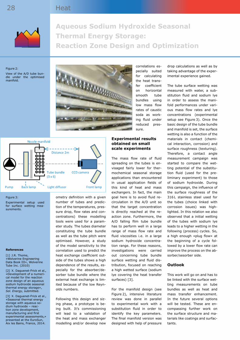
Figure 1:
Detail of a tube col-umn and parameters for 1 ≤ n ≤ N.
28 Heat
ometry definition with a given number of tubes and predic-tion of the temperatures, pres-sure drop, flow rates and con-centrations) these modelling tools were used for a param-eter study. The tubes diameter constituting the tube bundle as well as the tube pitch were optimised. However, a study of the model sensitivity to the correlation used to predict the heat exchange coefficient out-side of the tubes shows a high dependence of the results, es-pecially for the absorber/de-sorber tube bundle where the external heat exchange is lim-ited because of the low Reyn-olds numbers.
Following this design and siz-ing phase, a prototype is be-ing built. It’s commissioning will lead to a validation of the heat and mass exchanger modelling and/or develop new
correlations es-pecially suited for calculating the heat trans-fer coefficient on horizontal smooth tube bundles using low mass flow rates of caustic soda as work-ing fluid under reduced pres-sure.
Experimental results obtained on small scale experiments
The mass flow rate of fluid spreading on the tubes is en-visaged fairly lower for ther-mochemical seasonal storage applications than encountered in usual application fields of this kind of heat and mass exchangers. In fact, the main goal here is to avoid fluid re-circulation in the A/D unit so that the target concentration is directly reached at the re-action zone. Furthermore, the A/D falling film tube bundle has to perform well in a large range of mass flow rate and fluid viscosities i.e. in a large sodium hydroxide concentra-tion range. For these reasons, investigations were carried out concerning tube bundle surface wetting and fluid dis-tribution, focused on reaching a high wetted surface (sodium lye covering the heat transfer surfaces) [3].
For the manifold design (see Figure 2), intensive literature review was done in parallel to experimental work with a substitution fluid in order to identify the key parameters. The final manifold version was designed with help of pressure
drop calculations as well as by taking advantage of the exper-imental experience gained.
The tube surface wetting was measured with water, a sub-stitution fluid and sodium lye in order to assess the mani-fold performances under vari-ous mass flow rates and lye concentrations (experimental setup see Figure 3). Once the basic design of the tube bundle and manifold is set, the surface wetting is also a function of the materials in contact (chemi-cal interaction, corrosion) and surface roughness (texturing). Therefore, a contact angle measurement campaign was started to compare the wet-ting potential of the substitu-tion fluid (used for the pre-liminary experiment) to those of sodium hydroxide. During this campaign, the influence of the surface roughness of the 316 L stainless steel used for the tubes (choice linked with corrosion issues) was high-lighted. In this relation we also observed that a initial wetting of the tubes with sodium lye leads to a higher wetting in the following (process) cycles. So, a high enough «plug flow» at the beginning of a cycle fol-lowed by a lower flow rate can improve the process on the ab-sorber/sesorber side.
Outlook
This work will go on and has to be linked with the surface wet-ting measurements on tube bundles as well as heat and mass transfer enhancement. In the future several options will be tested. These are en-compassing further work on the surface structure and ma-terials like coatings and surfac-tants.
Aqueous Sodium Hydroxide Seasonal Thermal Energy Storage: Reaction Zone Design and Optimization
References
[1] J.R. Thome, «Wolverine Engineering Data Book III», Wolverine Tube Inc. (2010)
[2] X. Daguenet-Frick et al., «Development of a numeri-cal model for the reaction zone design of an aqueous sodium hydroxide seasonal thermal energy storage», Sol. Energy, submitted.
[3] X. Daguenet-Frick et al., «Seasonal thermal energy storage with aqueous so-dium hydroxide – reac-tion zone development, manufacturing and first experimental assessments,» presented at the EuroSun, Aix les Bains, France, 2014.
Figure 3:
Experimental setup used for surface wetting mea-surements.
Figure 2:
View of the A/D tube bun-dle under the optimised manifold.

29

HydrogenProduction and Storage
Illu
stra
tion
: Je
ff K
ubin
a

31 Hydrogen
Illu
stra
tion
: Je
ff K
ubin
a
Sustainable Electrocatalysts for Hydrogen Production Using Renewable Energy
Author
Kevin Sivula¹
¹ EPFL
List of abbreviations
DCB 1,2-Dichloroben-zene
EG Ethylene Glycol
LSV Linear Scanning Voltammetry
NMP N-Methylpyrrol-idone
SP Sodium Palmitate
SCSA Space-Confined Self-Assembled
TMD Transition Metal Dichalcogenide
Status of project and main scientific results of workgroups
Scope of project
One challenge in the production of hydrogen from renewable energy using water electolysis at low current density (i.e. at ca. 10 mA cm–2 for photoelectochemical applications) is the identification of inexpensive and scalable catalyst materials to reduce the overpotential required to drive the water oxidation and reduction reactions. While Platinum is traditionally used for the water reduction half-reaction, it is not scalable to the terawatt range necessary. Abundant transition metal dichalcogenides (TMDs), MoX2 or WX2 (X = S or Se), have been identified as promising replacements for Pt in this application [1, 2]. However, the further development of high performance energy conversion devices using these materials, and their ultimate practical applica-tion, is hindered by the lack of a controllable method to fabricate large-area and continuous thin films with controllable 2D layer orientation and suitable contact to the electrode substrate. While physical or chemical vapor deposition techniques can offer good control over thin-film prepa-ration [3, 4], these methods require high temperatures and vacuum, which are less suitable for the economical production of large-area energy conversion devices. Solution-based processing meth-ods, in contrast, offer a viable route. Indeed, the chemical exfoliation of TMDs (using lithium in-tercalation) can afford stable dispersions of 2D flakes suitable for controllable film formation [5]. However, the concurrent change from the 2H-phase to the 1T-phase during chemical exfoliation is undesirable for many applications [6, 7]. Alternatively solvent-assisted exfoliation [8, 9, 10] can yield 2D flakes, though, due to the defect-free flake surfaces produced, obtaining stable dispersions at high concentration and processing them into uniform thin films without layer restacking remain significant challenges.
This year we have achieved advances in the exfoliation and solution processing of 2D MoS2 that were subsequently leveraged to prepare and elec-tronically probe homogeneous multi-flake thin-film devices [11]. We first found that a polymer formed when using 1,2-dichlorobenzene (DCB) as a solvent is produced from the decomposition of the solvent during the sonication-assisted solvent exfoliation of MoS2. To examine the role of the SP on the exfoliation we added pre-synthesized SP to NMP, how-ever no increase in MoS2 con-centration after sonication was observed. In addition, when 1 % ethanol was added to the DCB to inhibit SP formation [12], a similar concentration to that of the NMP exfoliation was observed. These observations clearly indicate that sonop-olymer formation itself during exfoliation is an essential pro-
cess for high yield of exfoliated MoS2. Indeed, stable disper-sions up to 0.5 mg ml–1 of few-layer MoS2 flakes in the 2H phase were obtained after only 6 h of low-power sonication. After removing the sonopoly-mer using a washing proce-dure, alkyl-trichlorosilane sur-factants were used to prevent the restacking of 2D MoS2 lay-ers and create stable disper-sions with concentrations as high as 85 mg ml–1.
To enable the use of these solvent-dispersed 2D flakes of TMDs the development of deposition methods that can offer precise control over film thickness and morphology is a remaining challenge. Generally in solution-based nanoparticle thin-film formation, precipita-tion and aggregation lead to poor uniformity and inadequate contact with the substrate. While partial control over these
aspects can be achieved us-ing appropriate surfactants or nanoparticle surface ligands, conventional solution based coating techniques (drop coat-ing, spin coating or dip coat-ing) still typically give rise to agglomerated structures after solvent evaporation, especially for 2D materials [13].
As such, much work has fo-cused on applying the 2D tem-plate of a fluid/fluid interface for the assembly of nanomate-rials, followed by transfer to a solid substrate to achieve thin-film formation in a controlled manner. The self-assembly of nanoparticles at a liquid/air interface (the so-called Langmuir-Blodgett technique) is the prototypical example of this approach [14, 15], and employing a liquid/liquid inter-face is a promising extension suitable for large-aspect ratio 2D materials [13]. Typically

32 Hydrogen
in liquid/liquid self-assembly techniques, nanoparticles dis-persed in a hydrophilic phase are driven to a hydrophilic/hydrophobic interface using mechanical agitation or an inducing agent [13, 16, 17]. For example in seminal work by Vanmaekelbergh and co-workers, ethanol was used as an inducer for the self-assem-bly of gold nanoparticles at a water-heptane interface [18]. Recently, Jia et al. presented a similar approach with 2D sulphonated graphene by first dispersing the particles in the inducing solvent (ethanol) and injecting them into the water layer [19]. However, solvent-exfoliated semiconducting TMD flake dispersions show poor stability in most solvents.
Indeed, our attempts to apply traditional liquid/liquid self-as-sembly techniques were unsuc-cessful even with alkyl-trichlo-rosilane functionalized TMDs, as we observed aggregation during the flake migration and film organization processes rather than homogeneous film formation. Therefore, to en-able the self-assembly of 2D TMDs we developed an ap-proach to spatially confine the particles at the interface of two immiscible non-solvents for
the TMD flakes, i.e. ethylene glycol (EG) and hexane. Our space-confined self-assembled (SCSA) thin film deposition method proceeds as follows. First, the WSe2 dispersion is injected into the hexane layer near the EG/hexane interface. As the hexylamine rapidly di-lutes into the hexane layer the flakes become confined by the two non-solvents and quickly align with the 2D interface. In-creasing the loading of flakes leads to in-plane self-compres-sion and generates a compact 2D self-assembly of the TMD. Next, the hexane layer is re-moved from the top leaving the self-assembled thin-film float-ing on the surface of the EG. The EG can then be removed from the bottom (through frit-ted glass) affording the depo-sition of the SCSA WSe2 film on a chosen substrate (e.g. con-ductive F:SnO2 coated glass, metal foils, or flexible Sn:In2O3 coated PET plastic). Finally, the film is dried at 150 °C to re-move any residual EG and im-prove film adhesion.Thin film electrodes, prepared with MoS2 (ca. 20 nm) on F:SnO2 coated glass gave uniform and homo-geneous morphology (see Fig-ure 1a) with high surface area suitable as a catalyst. Indeed initial results suggested that
the electrodes performed well as water reduction catalysts (Figure 1b). Linear scanning voltammetry (LSV) of the elec-trodes revealed an overpoten-tial of ca. 0.4 V for 10 mA cm–2 water reduction current densi-ty. However, subsequent scan-ning of the electrode afforded a significant reduction of the overpotential to only 0.2 V for 10 mA cm–2. While this initial result is promising, a further understanding of the electro-chemical performance of these electrodes is needed to further reduce the overpotential.
Future work includes the study of the surface (catalytic) sites on the surface of the TMD cat-alysts by electrochemical im-pedance spectroscopy and the optimization of the electrode fabrication procedure. Overall, the ability to make MoS2 thin films enabled by our material processing techniques can be a valuable tool to aid the under-standing and improvement of charge transport and transfer in these materials for applica-tion in other electrochemical and optoelectronic devices. Thus extension of our methods to other TMDs and additional devices is also under develop-ment.
Figure 1. Characterization of MoS2 catalyst thin films.
Panel a (left) shows the scanning electron microscope (top down) image. Panel b (right) shows the linear scanning voltammetry of the MoS2 electrode in 1 M H2SO4 electrolyte.
References
[1] T.F. Jaramillo et al., Science, 317 (5834), 100–102 (2007).
[2] J. Kibsgaard et al., Nat. Mater. 11 (11), 963–969 (2012).
[3] K.-K. Liu et al., Nano Lett., 12 (3), 1538–1544 (2012).
[4] A. Tarasov et al., Adv. Funct. Mater., 24 (40), 6389–6400 (2014).
[5] Z. Zhiyuan et al., Angew. Chem. Int. Ed., 50 (47), 11093–11097 (2011).
[6] D. Voiry et al., Nano Lett., 13 (12), 6222–6227 (2013).
[7] D. Voiry et al., Nat. Chem., 7 (1), 45–49 (2015).
[8] G. Cunningham et al., ACS Nano, 6 (4), 3468–3480 (2012).
[9] V. Nicolosi et al., Science, 340 (6139), 1420–1437 (2013).
[10] H. Udayabagya et al., Nat. Commun., 4, 2213–2219 (2013).
[11] X. Yu et al., Chem. Mater., 26 (20), 5892–5899 (2014).
[12] S. Niyogi et al., J. Phys. Chem. B, 107 (34), 8799–8804 (2003).
[13] S. Biswas et al., Nano Lett., 9 (1), 167–172 (2008).
[14] H. Tachibana et al., Synth. Met., 102 (1–3), 1485–1486 (1999).
[15] H. Tachibana et al., Chem. Mater., 12 (3), 854–856 (2000).
[16] F. Kim et al., Adv. Mater., 22 (17), 1954–1958 (2010).
[17] L. Hu et al., Adv. Mater., 23 (17), 1988–1992 (2011).
[18] F. Reincke et al., Angew. Chem. Int. Ed., 43 (4), 458–462 (2004).
[19] B. Jia et al., RSC Adv., 4 (65), 34566–34571 (2014).
Sustainable Electrocatalysts for Hydrogen Production Using Renewable Energy

33 Hydrogen
Figure 1:
Concept of the dual-circuit RFB. Hydrogen is gener-ated by the chemical dis-charge of the negative electrolyte.
Demonstration of a Redox Flow Battery to Generate Hydrogen from Surplus Renewable Energy
Authors
Amstutz Véronique¹Heron Vrubel¹Pekka Peljo¹Kathryn E. Toghill¹Hubert H. Girault¹
¹ EPFL
List of abbreviations
RFB Redox Flow Battery
Status of project and main scientific results of workgroups
Scope of project
The present demonstration project finds its roots in a concept developed in our laboratory, which primarily aims at increasing the energy density of redox flow batteries (RFBs). The system is ex-tensively explained elsewhere ([1], [2]), but, in a few words, the idea is to use the RFB in a con-ventional way except when a surplus of (renewable) energy is available and the battery is already fully charged. In this particular case, a secondary circuit (see Figure 1) made of two catalytic beds enables an external chemical discharge of both electrolytes. On the negative side (right circuit in Figure 1), the catalytic discharge reaction is the reduction of protons by the V(II) species present in the electrolyte, generating hydrogen and regenerating the discharged V(III) species. The catalyst for this reaction is molybdenum carbide, which was chosen for its low price and its clear activity for the reaction of hydrogen evolution in an acidic V(II) solution. On the positive side (left circuit in Figure 1), catalysts such as iridium dioxide (IrO2) or ruthenium dioxide (RuO2) are able to activate the oxidation of water by the Ce(IV) ions, generating oxygen and protons that can cross the membrane and re-equilibrate the proton concentration on the negative electrolyte, and regenerating the discharged Ce(III) species. Both discharged electrolytes return then to the RFB, which can be charged further, storing thus sur-plus energy in the form of hydrogen. This increases the RFB energy density. The efficiency of this system in chemical discharge mode is calculated by comparison of the chemical energy hold by the hydrogen produced and the electrical energy used for charging the V–Ce RFB. Using a bench-scale system, this efficiency was about 50 %.
tions was planned, financed, designed and built.
This demonstration system was installed on the site of the the water treatment facil-ity (STEP), in Martigny. This
project has been conducted in collaboration with Sinergy, the utility company of Martigny, and CREM, a research cen-ter on energy conversion also based in Martigny. The project was also funded by the Federal
Once the proof-of-concept system was established in the laboratory, a larger system aiming at the demonstration of the feasibility of the process of chemical discharge for produc-tion of hydrogen in real condi-

34 Hydrogen
Figure 2 (left):
Secondary circuit for the reaction of hydrogen evo-lution as a chemical dis-charge of the negative electrolyte of the RFB.
Figure 3 (right):
The 10 kW/40 kWh RFB in-stalled on the demonstra-tion site in Martigny.
Demonstration of a Redox Flow Battery to Generate Hydrogen from Surplus Renewable Energy
Office of Energy and the district of Martigny and was planned to last for two years, starting from January 2014. Its specific goals were primarily to define the potential of the dual-circuit RFB for larger scale applica-tions and to establish its feasi-bility, but also to provide some time for a proper design and scaling-up of its catalyst and catalytic beds.
In a first step, a commercially available 10 kW/40 kWh all-vanadium RFB was bought and installed (Figure 2), which was in a second step fully charac-terised in order to understand in details its modes of opera-tion. The design of the cata-lytic bed lead to a horizontal, segmented configuration (hor-izontal tubes of Figure 3) of the reactor in order to facilitate a maximum use of the catalyst, but, more importantly, to fa-vour convection of hydrogen bubbles from the liquid phase to the gas.
The design of the catalyst was also an essential aspect of the scale-up of the dual-circuit RFB. Indeed, the commer-cial Mo2C powder used in the bench-scale system could not be employed as it was lead-ing to a strong resistance to the electrolyte flow through the catalytic bed, but also to trapped H2 bubbles in the cata-lytic bed itself. We developed therefore a catalyst consisting of Mo2C nanoparticles deposit-ed on a ceramic bead support. These catalytic beads and this catalytic bed were success-fully tested for the chemical discharge of the negative elec-trolyte of the RFB. However, some optimization will still be required to have a long-term stable catalytic bed.
In the framework of the dem-onstration project in Martigny, an open-day was organized on 12th November 2014. The same day, an official open-ing ceremony for the site and the project was celebrated
with about 60 participants. A previous less official opening ceremony, taking place on 26th May, gathered about 20 par-ticipants for a thorough visit of the site and a dinner.
In terms of public outreach, the project was featured on Canal 9 news on 26th May. On 12th November the project was included in the news on RTS and Canal 9, and an article about the project appeared in the newspaper 24Heures. The project was also featured on the EPFL Mediacom website, and in a Youtube video pro-duced by Mediacom at EPFL.
References
[1] V. Amstutz et al., «Redox flow battery for hydrogen generation», WO Patent Application N° WO2013131836 A1, 2013.
[2] V. Amstutz et al., «Renewable hydrogen generation from a dual-circuit redox flow battery», Energy Environ. Sci., 7, 2350–2358 (2014).
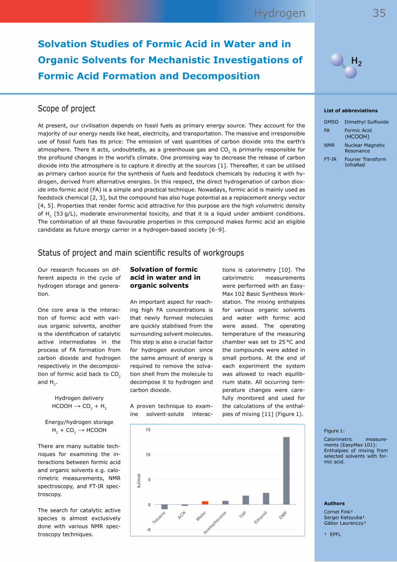
35 Hydrogen
Solvation Studies of Formic Acid in Water and in
Organic Solvents for Mechanistic Investigations of
Formic Acid Formation and Decomposition
Authors
Cornel Fink¹Sergei Katsyuba¹Gábor Laurenczy¹
¹ EPFL
List of abbreviations
DMSO Dimethyl Sulfoxide
FA Formic Acid (HCOOH)
NMR Nuclear Magnetic Resonance
FT-IR Fourier Transform InfraRed
Status of project and main scientific results of workgroups
Scope of project
At present, our civilisation depends on fossil fuels as primary energy source. They account for the majority of our energy needs like heat, electricity, and transportation. The massive and irresponsible use of fossil fuels has its price: The emission of vast quantities of carbon dioxide into the earth’s atmosphere. There it acts, undoubtedly, as a greenhouse gas and CO2 is primarily responsible for the profound changes in the world’s climate. One promising way to decrease the release of carbon dioxide into the atmosphere is to capture it directly at the sources [1]. Thereafter, it can be utilised as primary carbon source for the synthesis of fuels and feedstock chemicals by reducing it with hy-drogen, derived from alternative energies. In this respect, the direct hydrogenation of carbon diox-ide into formic acid (FA) is a simple and practical technique. Nowadays, formic acid is mainly used as feedstock chemical [2, 3], but the compound has also huge potential as a replacement energy vector [4, 5]. Properties that render formic acid attractive for this purpose are the high volumetric density of H2 (53 g/L), moderate environmental toxicity, and that it is a liquid under ambient conditions. The combination of all these favourable properties in this compound makes formic acid an eligible candidate as future energy carrier in a hydrogen-based society [6–9].
Our research focusses on dif-ferent aspects in the cycle of hydrogen storage and genera-tion.
One core area is the interac-tion of formic acid with vari-ous organic solvents, another is the identification of catalytic active intermediates in the process of FA formation from carbon dioxide and hydrogen respectively in the decomposi-tion of formic acid back to CO2 and H2.
Hydrogen delivery HCOOH → CO2 + H2
Energy/hydrogen storage H2 + CO2 → HCOOH
There are many suitable tech-niques for examining the in-teractions between formic acid and organic solvents e.g. calo-rimetric measurements, NMR spectroscopy, and FT-IR spec-troscopy.
The search for catalytic active species is almost exclusively done with various NMR spec-troscopy techniques.
Solvation of formic acid in water and in organic solvents
An important aspect for reach-ing high FA concentrations is that newly formed molecules are quickly stabilised from the surrounding solvent molecules. This step is also a crucial factor for hydrogen evolution since the same amount of energy is required to remove the solva-tion shell from the molecule to decompose it to hydrogen and carbon dioxide.
A proven technique to exam-ine solvent-solute interac-
tions is calorimetry [10]. The calorimetric measurements were performed with an Easy-Max 102 Basic Synthesis Work-station. The mixing enthalpies for various organic solvents and water with formic acid were assed. The operating temperature of the measuring chamber was set to 25 °C and the compounds were added in small portions. At the end of each experiment the system was allowed to reach equilib-rium state. All occurring tem-perature changes were care-fully monitored and used for the calculations of the enthal-pies of mixing [11] (Figure 1).
Figure 1:
Calorimetric measure-ments (EasyMax 101): Enthalpies of mixing from selected solvents with for-mic acid.

36 Hydrogen
References
[1] B. Hu et al., «Thermal, electrochemical, and photochemical conver-sion of CO2 to fuels and value-added products», J. of CO2 Utilization 1 (0), 18–27 (2013).
[2] E. Balaraman et al., «Efficient hydrogenation of organic carbonates, carbamates and formates indicates alternative routes to methanol based on CO2 and CO», Nat. Chem., 3 (8), 609–614 (2011).
[3] G. Centi et al., «Opportunities and prospects in the chemical recycling of carbon dioxide to fuels», Catalysis Today, 148 (3–4), 191–205 (2009).
[4] W. Wang et al., «Recent advances in catalytic hydrogenation of carbon dioxide», Chem. Soc. Rev., 40 (7), 3703–3727 (2011).
[5] A.F. Dalebrook et al., «Hydrogen storage: beyond conventional methods», Chem. Commun., 49 (78), 8735-8751 (2013).
Another established method to observe molecular interactions is NMR spectroscopy. Again, several FA/solvent systems were examined carefully. Ex-emplarily for others, the find-ings of the water/formic acid studies will be discussed in greater detail. 1H, 13C and 17O NMR spectra of numerous mix-tures, ranging from pure water to pure formic acid, were re-corded. A sensitive indicator for the changes in the chemi-cal interactions at different mixing ratios is the chemical shift of the proton linked to the carbon of the FA (HCOOH, Fig-ure 2). An external standard (benzene-d6) [12] was used for locking and referencing the samples. Chemical shifts can be used to calculate how
the solvent molecules are co-ordinated around a formic acid molecule.
To gain more information about the solute-solvent interactions of FA in aqueous solutions, we carried out FT-IR spectro-scopic studies. The interac-tions between formic acid and water were measured at differ-ent concentrations (Figure 3). Varied concentrations cause alterations in the chemical in-teractions. These alterations can be seen as characteristic changes in the FT-IR absorp-tion spectra. Indicative are the frequencies of isolated IR bands, mainly caused by mo-lecular vibrations of the νC=O and νC-H bond (Table 1).
Mechanistic studies on formic acid formation and decomposition
In catalytic reactions interme-diates are of special interest. Difficulties in their observation arise from their short life times and generally low abundance – not seldom close to the de-tection limit of NMR spectros-copy. Therefore, sophisticated techniques are required to re-veal catalytic processes [13]. For example, to investigate the formation of formic acid, a carefully measured amount of solvent and catalyst are added into medium pressure sapphire NMR tubes. Then, the tubes are pressurized with hydrogen and carbon dioxide (up to 100 bar) and exposed to heat. The de-composition of formic acid can be either observed at ambient conditions or at elevated pres-sures (maximal 100 bar), de-pending on the experimental design.
Last year, we published the re-sults [14] of the very promis-ing catalyst [RuCl2(PTA)4]. It produces unprecedented high concentrations of formic acid in DMSO (2.2 M) without any additives necessary. Our re-search is now concerned with the analysis of the catalytic intermediates of these reac-tion. The mechanistic studies
Solvation Studies of Formic Acid in Water and in
Organic Solvents for Mechanistic Investigations of
Formic Acid Formation and Decomposition
Figure 2:
NMR spectroscopy: Shift of the acidic proton from formic acid as function of changing water-formic acid concentrations.
Table 1:
FT-IR: Frequencies of eas-ily assignable and isolated IR bands of stretching vi-brations of C=O and C-H moieties (νC=O and νC-H, respectively) of formic acid.
References
a) R.C. Millikan, K.S. Pitzer, J. Chem. Phys., 27, 1305–1308 (1957).b) L. George, W. Sander, Spectrochim. Acta A, 60, 3225–3232 (2004).

37 Hydrogen
References
[6] F. Joó, «Breakthroughs in Hydro-gen Storage—Formic Acid as a Sustainable Storage Material for Hydrogen», ChemSusChem, 1 (10), 805–808 (2008).
[7] S. Enthaler, «Carbon Dioxide—The Hydrogen-Storage Material of the Future?» ChemSusChem, 1 (10), 801–804 (2008).
[8] R. von Helmolt et al., «Fuel cell vehicles: Status 2007», J. Power Sources, 165 (2), 833–843 (2007).
[9] M. Grasemann et al., «Formic acid as a hydrogen source – recent develop-ments and future trends», Energy Environ. Sci., 5 (8), 8171–8181 (2012).
[10] R. Haase et al., «Enthalpies of mixing for binary liquid mixtures of monocarbonic acids and alcohols», Zeitschrift für Naturforschung, 40 (9), 947 (1985).
[11] H. Fujiwara, «Studies of hydrogen bonding in carboxylic acid-dimethyl sulfoxide systems by nuclear magnetic reso-nance dilution shifts», J. Phys. Chem., 78 (16), 1662–1666 (1974).
[12] S.K. Bharti et al., «Quantitative 1H NMR spectroscopy», TrAC, Trends Anal. Chem., 35 (0), 5–26 (2012).
[13] A. Thevenon et al., «Formic Acid Dehydro-genation Catalysed by Tris(TPPTS) Ruthenium Species: Mechanism of the Initial ‹Fast› Cycle», ChemCatChem, 6 (11), 3146–3152 (2014).
[14] S. Moret et al., «Direct synthesis of formic acid from carbon dioxide by hydrogenation in acidic media», Nat. Commun., 5 (2014).
Figure 4:
1H NMR: The two dominating signals in the hydride region of [RuCl2(PTA)4], an indicator for a catalytically active species (400 MHz 1H spectrum, 5 mm sapphire tube at 91 bar H2 pressure, water suppression, ex-ternal standard (DMSO-d6)).
Figure 3:
FT-IR spectroscopy: The strong changes in the ab-sorption band are indicat-ing the strong interactions between the solvent (wa-ter) and the solute (formic acid).
are carried out with a 400 MHz NMR spectrometer and the measurements are performed in a hydrogen atmosphere in 5 or 10 mm sapphire NMR tubes. To study hydride species, the catalyst gets dissolved in puri-fied, deionized water (640 µL) and pressured with pure hy-drogen. As before, an external standard (benzene-d6) is used. The hydride region revealed
two distinct signals: A doublet at -8.78 ppm and a triplet at -11.91 ppm (Figure 4). Both hydride signals collapse to sin-gle peaks in case of phospho-rus decoupling. We know from structural analysis that the phosphorus is directly bound to the central ion. Hence, the two hydrides are most certainly lo-cated in the first coordination sphere of the complex, which
is a strong support for identi-fying them as catalytically ac-tive species. Further research is necessary to improve our understanding of the mecha-nisms behind these catalytic processes.
Acknowledgement
SCCER, CTI and EPFL are thanked for financial support.
Solvation Studies of Formic Acid in Water and in
Organic Solvents for Mechanistic Investigations of
Formic Acid Formation and Decomposition

38 Hydrogen
Hydrogen Storage in Hydrides
Authors
Andreas Züttel¹ Züleyha Özlem Kocabas Atakli¹ Elsa Callini¹ Shunsuke Kato¹
¹ EPFL and Empa
List of abbreviations
XPS X-ray Photoelec-tron Spectros-copy
Scope of project
The main achievements of our work in 2014 are the description of the reaction mechanism of the hydrogen desorption from alanates and first experiments for the analysis of the reduction of CO2 on metal hydride surfaces.
Status of project and main scientific results of workgroups
Complex hydrides
In 1996 Bogdanovic presented [1, 2] first results of hydro-gen sorption experiments on Ti-catalized NaAlH4. Pressure-concentration isotherms were measured in a temperature range of 150 °C to 244 °C and two distinct and flat plateaus were found. The corresponding reactions are: • 3NaAlH4 ⇌ Na3AlH6 + 2Al +
3H2 and • Na3AlH6 ⇌ 3NaH + Al + 3/2H2 The corresponding enthal-pies for the reactions, de-termined by the Van’t Hoff plot are, ΔH1 = 111 kJ and ΔH2 = 70.5 kJ, respectively.
This finding has initiated a new research field and hydrogen storage in complex hydrides became feasible. The Ti cata-lyst shows a reduction of the activation energy for the two
reactions from 118 kJ/mol H2 to 80 kJ/mol H2 and from 124 kJ/mol H2 to 96 kJ/mol H2, respectively. Some years later first results on hydrogen de-sorption from borohydrides were presented. Borohydrides are similar compounds like alanates, however, no hexa-hydride phase is observed and until now no catalyst was found for the hydrogen sorp-tion reaction in borohydrides.
Borohydrides contain up to 20 mass% of hydrogen and, therefore, store an order of magnitude more hydrogen as compared to metal hydrides. Despite the large number of publications [3] on the func-tion of the catalyst in alanates only recently a new and con-sistent model for the mecha-nism of the Ti catalyst in alkali alanates was described, based on the local structure and ther-modynamic considerations [4].
The mechanism is based on the fact, that in both reaction steps of the hydrogen desorp-tion from NaAlH4 the ions Na+ and H- have to be moved from the complex (Na+[AlH4]
-) to the neighboring NaAlH4 and from the hexahydride (3Na+[AlH6]
3-) to the elemental hydride NaH (Figure 1). The activation en-ergy is determined by the charge separation, i.e. the role of the catalyst is to bridge be-tween Na+…Ti…H- and, there-fore, allow the two ions to be moved simultaneously without
forming NaH. The abundant AlH3 spontaneously decompos-es and releases hydrogen.
The hydrogen desorption mechanism of borohydrides is still not known. Due to the absence of a hexahydride phase, the elemental hydride is directly formed during the hydrogen desorption reaction, e.g. LiBH4 → LiH + BH3. The BH3 molecules in analogy to AlH3 spontaneously decompose (at T > 200 °C) or two BH3 can form the volatile B2H6 [5, 6]. The later reaction should be avoided, because it leads to a loss of boron from the material and diborane is poisonous gas for humans and fuel cells.
Reduction of CO2 on metal hydrides
To store renewable energy in synthetic hydrocarbons, two major challenges have to be overcome: • Extraction of CO2 from the
atmosphere close to the thermodynamic limit of en-ergy need.
• Reduction of CO2 with hy-drogen to specific hydro-carbons in a controlled end energy efficient reaction [7, 8].
The catalytic reduction of CO2 is determined by the local availability of hydrogen atoms and the orientation of CO2 mol-ecules. To control formation of C-C bonds and reaction paths
Figure 1:
Schematic representation of the hydrogen desorption reaction from NaAlH4.

39 Hydrogen
to synthesize specific energy-dense hydrocarbons from CO2, a new approach is CO2 reduc-tion on a modified substrate based on metal-hydrogen sys-tems (including metal clusters and nanoparticle compounds) (Figure 2). The aim is to eluci-date the CO2 reduction process in metal-hydrogen systems and to develop new reaction paths for formation of syn-thetic hydrocarbon as energy carriers.
The Ce-Co system was inves-tigated in view of the change of thermodynamic potential for CO2 reduction. Co is a cata-lytically active metal, for ex-ample, for the Fischer–Tropsch process. The formation of the Co hydride is an endothermic process. However, the forma-tion of the intermetallic com-pounds, for example CeCo3, lead to exothermic hydrogen absorption, forming the inter-stitial hydride CeCo3H4, and to ready hydrogen desorp-tion (endothermic) at ambi-ent pressures (Figure 2). The catalytic CO2 reduction takes place at the surface which ini-tially is covered with surface oxide layers, composed of ce-rium oxides. The redox prop-erty of ceria is a key factor in the catalytic activity of ceria-
based catalysts. Previously, we analysed in situ the oxida-tion state of ceria in reducing and oxidising gas atmospheres by a novel combination of near-ambient pressure X-ray photoelectron spectroscopy (XPS) and high-energy XPS at a synchrotron X-ray source [9]. Ceria is unique in that it reversibly stores and releases oxygen, which might assist CO2 reduction.
The intermetallic compound was synthesised by a metal-lurgical method (arc-melting, annealing, XRD structure analysis). The hydride powder was prepared by repeating a hydrogen absorption/desorp-tion cycle. The hydrogen de-sorption kinetics in various CO2 and CO atmospheres, as well as the catalytic activity, was analysed by using a fixed bed quartz tube reactor. At the surface of the hydride, CO ad-sorption significantly retards recombination of hydrogen and the subsequent hydro-gen release, compared to CO2. CO2 conversion commenced at 200 °C and found higher at the reduced surface by CO + H2.
In the course of the CO2 reduc-tion, CH4 was formed under our experimental conditions. The
formation of C2H6 was lower by one order of magnitude. In the formation of CH4, commenc-ing at 200 °C, there are two distinct regions. At the higher temperatures, the formation of CH4 was enhanced by pre-reduction of ceria and other oxides. On the other hand, the formation of CH4 commenced at 200 °C in both reactions. In the initial stage at 200 °C, CO molecules and the adsorbates, dissociated from CO2, retard recombination of hydrogen. There, the high availability of hydrogen might lead to a lo-cal C-H bonding in the catalytic CO2 reduction [10].
The understanding of the mechanism of the catalytic hydrogen desorption from the alanates is an excellent basis for the further development of new hydrogen storage materi-als. First results on the investi-gation of the CO2 reduction on metal hydrides and the detec-tion of C-C compounds rep-resent a very important step forward in the development of new catalysts for the synthesis of hydrocarbons.
Hydrogen Storage in Hydrides
References
[1] A. Züttel et al., J. Power Sources, 5194, 1–7 (2003).
[2] A. Züttel et al., «Tetrahydroborates as new hydrogen storage materi-als», Scripta Materialia, 56 (10), 823–828 (2007).
[3] T.J. Frankcombe, Chem. Rev., 112, 2164–2178 (2012)
[4] Züleyha Özlem Koca-bas Atakli et al., «Catalyzed Hydrogen Sorption Mechanism in Alkali Alanates», submitted to PCCP (2015)
[5] O. Friedrichs et al., «Role of Li2B12H12 for the Formation and Decomposi-tion of LiBH4», Chem. Mater., 22 (10), 3265–3268 (2010).
[6] S. Kato et al., «Effect of the surface oxidation of LiBH4 on the hydrogen desorption mechanism», PCCP, 12, 10950 (2010) .
[7] A.K. Geim et al., Nat. Mater., 6 (3), 183–191 (2007).
[8] R. Kötz et al., Electrochim. Acta, 45 (15-16), 2483–2498 (2000)
[9] S. Kato et al., Phys. Chem. Chem. Phys., 17, 5078 (2015).
[10] S. Kato, A. Züttel, et al, in preparation.
Figure 2:
Left: Catalytic CO2 reduc-tion reaction on the sur-face of a metal or metal hydride.
Right: Potential curves for activated chemisorption of hydrogen on a metal sur-face covered with a sur-face layer and exothermic solution in the bulk (sche-matic).

Synthetic FuelsDevelopment of Advanced Catalysists
Illu
stra
tion
: Beh
oldi
ngEy
e /
iSto
ck

41 Synthetic Fuels
Illu
stra
tion
: Beh
oldi
ngEy
e /
iSto
ck
New Catalysts for the Transformation of CO2 into Fuels
Author
Paul J. Dyson¹
¹ EPFL
List of abbreviations
NHC Nucleophilic Hetero-cyclic Carbene
TON Turnover Number
Status of project and main scientific results of workgroups
Scope of project
We are currently studying the reduction of CO2 into fuels such as formic acid, methane and metha-nol. Among these different fuels methanol is the most versatile and several heterogeneous catalysts have been reported for the direct hydrogenation to methanol. In all the cases harsh reaction condi-tions (over 200 °C) along with low turnover numbers (TON) are major drawbacks. In contrast homo-geneous catalyst systems that operate under relatively milder conditions (140 °C) with higher TONs of up to 221 have been reported [1]. Although promising, none of the catalysts reported are com-mercially viable. We have developed ultrathin sheets of palladium (figure 1) that catalyze the forma-tion of methanol when dispersed in solution. These sheets may be a single palladium layer thick and their full characterization is in progress. We intend to use these thin palladium sheets to coat vari-ous surfaces to generate highly dispersed heterogeneous catalysts that may be superior in activity to those currently reported. We also intend to apply the route used to generate these nanosheets to other metals such as nickel and bimetallic systems and explore their activity in methane and methanol forming reactions. Others in the working group may find uses for these nanosheets, e.g. in preparing electrodes for the electrocatalytic reduction of CO2.
We are also working on the reduction of CO2 to metha-nol using a two-step, one-pot method (figure 2) based on ho-mogeneous catalysis, although it should be possible to immo-bilize the molecular catalysts later in the study to give het-erogenous systems. The initial step involves CO2 fixation into diol compounds followed by in situ hydrogenation to gen-erate methanol. We believe, in this way we will be able to generate methanol under mild reaction conditions with higher TONs. Advantageously, this re-action needs only one equiva-lent of diol and once methanol is generated from the system the diol compound will again fix another equivalent of CO2 thereby generating a cyclic
process. The substrates could also be heterogenized, e.g. by attaching a vinyl group to the arene ring and then trans-forming them into a functional polymer, which should lead to the simple isolation of metha-nol.
We are also exploring non-vol-atile frustrated Lewis pair-type systems to trap hydrogen and CO2 and then convert them into fuels. The first system we
have prepared affords formic acid, but only under harsh con-ditions. We have also discov-ered metal free catalyst (NHC) for N-methylation reactions using CO2 as the carbon source and hydrosilane as the source of hydrogen [2] (figure 3). No-tably, the catalyst showed ex-cellent chemoselectivity and substrates scope for this reac-tion. We are now developing this strategy to fuel production using ionic liquid amines.
References
[1] S. Wasselbaum et al., Angew. Chem. Int. Ed., 51 (30), 7499–7502, (2014).
[2] S. Das et al., Angew. Chem. Int. Ed., 53 (47), 12876–12879, (2014).
Figure 1 (upper left):
Ultrathin palladium nano-sheet catalysts
Figure 2 (upper right):
Two step one pot genera-tion of methanol from CO2 under mild condition.
Figure 3 (below):
Functional group tolerance: nitro, keto, nitrile, alkene, alkyne, ether, ester.

42 Synthetic Fuels
Molecular Control and Understanding of Surface Chemistry
Author
Christophe Copéret¹
¹ EPFL
List of abbreviations
NMR Nuclear Magnetic Resonance
Status of project and main scientific results of workgroups
Scope of project
Heterogeneous catalysts, including photo and electrocatalysts, are essential to the development of cleaner and more efficient processes, a key for sustainable development of our society. On het-erogeneous catalysts, all – catalytic – events take place at the surface of the materials. However, despite years of research and many advances in characterization methods, the rational development of heterogeneous catalysts is often impeded by the lack of understanding of the surface chemistry. Our strategy has thus focused on the preparation of well-defined surface sites through the controlled functionalization of material surfaces and their detailed characterization – at the molecular level – by combining experimental and computational approaches (Scheme 1). Our ultimate aim is a predictive approach towards the design of functional materials with desired catalytic properties.
To this end, we work on: • the preparation of metal
oxide materials with con-trolled composition and ho-mogeneity;
• the control of site density and surface chemistry of these materials, includ-ing the understanding of detect sites [1] and the controlled growth of metal particles on top of oxide supports [2].
We also introduce organic functionalities in order to im-
mobilize highly active ho-mogeneous catalysts and to capitalize on the rational de-velopment of homogeneous catalysts [3].
In addition, we have devel-oped nuclear magnetic reso-nance (NMR) methods to ob-tain expedient and yet detailed information of surface sites through dynamic nuclear po-larization [4].
This approach has been very successful for the development
of highly active single-site catalysts with catalytic perfor-mances (e.g. olefin polymer-ization and metathesis), often surpassing both homogeneous and classical heterogeneous catalysts.
Within the aim to convert the excess electricity and CO2, a green house gas, into fuels, our goal is to develop more ef-ficient catalysts for chemical (hydrogenation) and electro-chemical conversion process-es.
References
[1] F. Rascon et al., «Molecular nature of sup-port effects in single-site heterogeneous catalysts: silica vs. alumina», Chem. Sci., 2, 1449 (2011).
[2] (a) D. Gajan et al., «Gold nanoparticles supported on passivated silica: access to an ef-ficient aerobic epoxidation catalyst and the intrinsic oxidation activity of gold», J. Am. Chem. Soc., 131, 14667 (2009). (b) F. Héroguel et al., «Simultaneous generation of mild acidic functional-ities and small supported Ir NPs from alumina-sup-ported well-defined iridium siloxide», J. Catal., 321, 81 (2015).
[3] M.P. Conley et al., «Mesostructured Hybrid Organic-Silica Materials: Ideal supports for well-defined heterogeneous organometallic catalysts», ACS Catalysis, 4, 1458 (2014).

43 Synthetic Fuels
We therefore focus our research on:
Molecular Control and Understanding of Surface Chemistry
References
[4] (a) A. Lesage et al., «Surface Enhanced NMR Spectroscopy by Dynamic Nuclear Polarisation», J. Am. Chem. Soc., 132, 15459 (2010). (b) A.J. Rossini et al., «Dynamic Nuclear Polar-ization Surface Enhanced NMR Spectroscopy», Acc. Chem. Res., 46, 1942–1951 (2013). (c) P. Wolf et al., «NMR Signatures of the Active Sites in Sn–beta Zeolite», Angew. Chem. Int. Ed., 53, 10179 (2014).
[5] M. Baffert et al., «Tailored Ru-NHC hybrid catalytic materials for the hydrogenation of CO2 in the presence of amine», ChemSusChem., 4, 1762 (2011).
[6] (a) M. Broda et al., «Sorbent enhanced methane reforming over a Ni-Ca-based, bi-functional catalyst sorbent», ACS Catalysis, 2, 1635–1646 (2012). (b) D. Baudouin et al., «Nickel-silicide colloid prepared under mild conditions as a versatile Ni-precursor for more efficient CO2 reforming of CH4 catalysts», J. Am. Chem. Soc., 134, 20624 (2012). (c) D. Baudouin et al., «Particle size effect in the low temperature reform-ing of methane by carbon dioxide on silica-supported Ni nanoparticles», J. Catal., 297, 27–34 (2013).
the conversion of CO2 into methanol. With this project, we are develop-ing more selective cata-lyst through the controlled growth of supported Cu nanoparticles and better (computational) models to improve these catalysts through a structure–activ-ity relationship.
• the development of pro-cesses for the capture and the conversion of CO2 [6].
We are developing so-called Sorbent Enhanced Reforming to capture CO2 and produce pure H2.
• the development of electro-catalysts for the formation of H2 and the direct conver-sion of CO2 into fuels. We are developing methods to control the shape and com-position of colloids towards the preparation of selective electro-catalysts for the conversion of CO2 to fuels.
• the development of hybrid materials for the immobili-zation of highly active ho-mogeneous CO2 hydroge-nation catalysts [3,5]. With this project, we have de-veloped new platform mol-ecules, which will be used to prepare hybrid materials to immobilize a new gen-eration of immobilized CO2 hydrogenation catalysts.
• the development of het-erogeneous catalysts for

44 Synthetic Fuels
Electrochemical CO2 Reduction
Authors
Julien Durst¹Yohan Paratcha¹Juan Herranz¹Mehtap Özaslan¹Thomas Gloor¹F.N. Büchi¹Thomas J. Schmidt¹
¹ PSI
List of abbreviations
DEMS Differential Elec-trochemical Mass Spectrometry
FTIR Fourier Transform Infrared Spectros-copy
HER Hydrogen Evolution Reaction
PTFE Polytetrafluoroeth-ylene
Status of project and main scientific results of workgroups
Scope of project
The electrochemical reduction of CO2 to hydrocarbon is a promising pathway for the recycling of this greenhouse gas. Nevertheless, on top of the high overpotential typically required to drive this reac-tion, the electrochemical reduction of CO2 suffers from a low faradaic efficiency (it is kinetically more favorable to evolve hydrogen in the hydrogen evolution reaction (HER) from water than to reduce CO2), and from a poor and/or uncontrolled yield of valuable products such as methanol or methane [1]. In this work package, several strategies will be employed at PSI’s Electrochemistry Laboratory in order to:• develop measurement tools for online and in operando detection of the reaction products in the
electrochemical reduction of CO2.• find the origin of the selectivity of specific electrode materials.• design electrocatalyst systems with high selectivity in the CO2 reduction towards valuable prod-
ucts such as methanol or methane.
In this first annual report, the focus is made on the develop-ment of online and in operando electrochemical tools, follow-ing two pathways.
Liquid electrolyte based electrochemical cell
The first approach makes use of a liquid electrolyte based electrochemical cell coupled to differential electrochemical mass spectrometry (DEMS) for the identification and quantifi-cation of produced volatile spe-cies such as methanol, formic acid, carbon monoxide, meth-ane or ethylene. In addition, a similar type of electrochemical cell coupled to a Fourier trans-form infrared spectroscopy (FTIR) setup for the detec-tion of reaction products and intermediates adsorbed onto the electrode surface was also built. This first approach offers a high flexibility when screen-ing multiple parameters, such as the nature or structure (single crystal electrodes vs. nanoparticles) of the electrode on which the electrochemical reduction occurs or the experi-mental operating conditions (pH and temperature).
While still working on improv-ing the design of the electro-chemical cell and setup, pre-liminary CO2 reduction results followed by DEMS were ob-tained on a polycrystalline Cu disk in 0.1 M KHCO3 saturated with CO2. In this setup, the working electrode is pressed on the PTFE membrane of the DEMS setup representing the inlet to the vacuum system as to allow the direct collection of the volatile reduction products. Even if this approach results in poorly-defined diffusion con-ditions near the electrode, it allows for the observation of qualitative reactivity trends described in the following.
In an exemplary experiment, the potential profile depicted in Figure 1 (A) is applied to the Cu disk electrode. Figure 1 (B–D) displays the time evolution of the mass fragment signals m/z = 2 (H2
+), m/z = 15 (CH3+)
and m/z = 44 (CO2+). Both H2
and hydrocarbon products are generated, in good agreement with the literature [1], while CO2 gets progressively con-sumed, confirming the viabil-ity of the vacuum and DEMS-setup.
Solid polymer electrolyte based electrochemical cell
The second approach for on-line and in operando detection of CO2 reduction reaction prod-ucts makes use of a solid poly-mer electrolyte based electro-chemical cell, in a similar way of how a water electrolysis cell is operating. It consists of a two compartment/electrode cell, each of them supplied with its own gas and separated from each other by an anion or a cation exchange membrane. The cathode compartment is operating in a CO2 rich atmo-sphere, and the outlet of this compartment is connected to a mass spectrometer. The main advantage of this approach over the one cited above is that it is operating in a dry state with a defined amount of water vapor entering each compartment of the cell. Since the presence of water is identi-fied to be the main reason for the high HER activities, high faradaic efficiencies for CO2 conversion are expected to be reached using this approach. This could then also boost the selectivity toward certain products and offer completely
References
[1] Y. Hori, in: C. Vayanas, et al (Eds.), «Modern Aspects of Electro-chemistry», Springer, New York, 89–189 (2008).
[2] K.C. Neyerlin et al., J. Electrochem. Soc., 154 (7), B631–B635 (2007).
[3] J. Sobkowski et al., J. Phys. Chem., 89, 365–369 (1985).

45 Synthetic Fuels
different insights on this reac-tion, compared to what could be learned from classical liq-uid electrolyte based electro-chemical measurements. In an actual CO2 co-electrolysis operation, CO2 is reduced at the cathode side, while O2 is produced at the anode (from the water splitting reaction), the overall cell voltage of a co-electrolysis cell being then the thermodynamical poten-tial calculated from the Nernst equation plus the sum of the overpotentials for these anodic and cathodic reactions. Nev-ertheless, in the first stage of this work package the anodic reaction will be the hydrogen oxidation, known to be a few orders of magnitude faster than the oxygen evolution, so that no additional overpoten-tial is required to activate this anodic reaction.
Designs of electrodes fulfilling the criteria of an optimal oper-ation in such an electrochemi-cal cell are different than in the first approach proposed here (the liquid electrolyte cell), and offer less flexibility in terms of the electrode structures which can be tested. Gas diffusion electrodes in the form of car-bon supported metal particles in the nanometer range, with a high open porosity (> 60 %), are typically used for such type of operation so as to allow a high fraction of active sites (due to the nanometric size of the electrocatalysts) and a fast diffusion of the reactants and removal of the products.
Coupling of the two ap-proaches
It seems clear why coupling both of the two approaches presented here is pivotal: the
first will allow a fast screening of several electrode materi-als/structures in order to find design criteria for electrocata-lysts with high selectivity to-ward production of hydrocar-bons, which should then be applied in the synthesis of car-bon supported metal nanopar-ticles to be used in an actual co-electrolysis cell.
To evaluate the viability of this second approach, a carbon supported platinum catalyst (Pt/C) was tested as a CO2 re-duction catalyst. It is known that Pt is a catalyst with one of the lowest faradaic efficien-cies for CO2 reduction, since only H2 is being released [1]. Nevertheless, this result has been derived from measure-ments performed in liquid electrolytes, where it is known that due to the very fast HER kinetics and the limited diffu-sivity of H+/H2 in liquid phase, it is impossible to polarize a Pt electrode at potentials low enough, i.e. significantly below 0 VRHE where the CO2 reduction reaction is thermodynamically possible. This could actually be solved by using the solid poly-mer electrolyte based electro-chemical cell approach, oper-ating in a gas phase type of environment, where 3 orders of magnitude larger current densities (in A/cm2
geo) can be reached compared to a classi-cal liquid electrochemical cell due to faster H+/H2 diffusivi-ties. This approach has already been used before to quantify HER kinetics [2], where low Pt loadings (in cm2
Pt/cm2geo) have
been employed to reach large specific currents (in A/cm2
Pt). The same strategy as in refer-ence [2] has been applied here, and potentiostatic voltammo-grams (Figure 2A) have been
recorded in 1 atm of N2 (black trace) and CO2 (red trace). The voltammogram record-ed in the N2-sat. envi-ronment, where only H2 evolution occurs on the Pt/C electrode, leads to similar per-formance than those evaluated elsewhere [2]. Under CO2-sat. conditions, the elec-trolysis performance is 4-times lower than un-der N2-sat. conditions (Figure 2 A). This can be rationalized by the partial adsorption of CO2 onto the Pt cata-lyst surface [3], which lowers the number of active sites for the hydrogen evolution. The time-dependent MS profile re-corded during electrolysis (Fig-ure 2 B) allows concluding that only H2 was generated during both electrolysis modes, even in the CO2-rich atmosphere (no signals on the mass fragments patterns m/z = 15, 27, 31 for methane, ethylene or metha-nol were observed). As a con-clusion, even under conditions where Pt could be polarized at low potentials (here below 0.6 VRHE), its faradaic efficiency toward CO2 reduction remains negligible.
Outlook
After demonstrating the viability of both approaches, the fo-cus will be set on finding the origin of the selectivity of spe-cific electrode mate-rials, with a special care on Cu-based catalysts.
Figure 1:
Potential steps in cathodic region of Cu (A). Ion cur-rent recorded by MS for mass fraction m/z = 2 (B), m/z = 15 (C) and m/z = 44 (D).
Figure 2:
(A) HFR corrected voltam-mogram recorded at room temperature in 1 bar N2 (black trace) and 1 bar CO2 (red trace) and (B) corre-sponding time dependent evolution of mass fraction m/z = 2.
Electrochemical CO2 Reduction

46 Synthetic Fuels
Towards a Mechanistic Understanding of the Electro-Reduction of CO2
Authors
M.T.M Huynh¹H. Nguyen¹Y. Fu¹A. Rudnev¹A. Kuzume¹N. Luedi¹P. Broekmann¹
¹ University Bern
List of abbreviations
HER Hydrogen Evolution Reaction
NND Nearest-Neighbour Distance
STM Scanning Tunnelling Microscopy
Status of project and main scientific results of workgroups
Scope of project
The atomic structure of a single-crystalline copper electrode has been studied under in operando conditions by scanning tunnelling microscopy (STM) during hydrogen evolution which is considered as an important parasitic side-reaction of the CO2 electro-reduction. It is demonstrated that the hydrogen evolution reaction (HER) leads to significant changes in the electronic and geometric struc-ture of the copper electrode due to H-intercalation.
The focus of this current SC-CER project is on the conver-sion of the environmentally unfriendly green-house gas CO2 into hydrocarbons (ethyl-ene, methanol etc.) by means of (photo-)electrochemical processing (Figure 1). The par-ticular technological challenge is related to the extraordinary stability of the CO2 molecule thus requiring extremely high over-potentials for the elec-trochemical reduction. Only by the use of proper reaction
catalysts the CO2 reduction can be accelerated so that the process might become feasible in future from an economic point of view. Up to now, only copper-based catalysts have shown a promising activity to-wards the CO2 conversion into the desired hydrocarbons [1, 2]. However, their selectivity towards specific reaction prod-ucts (e.g. ethylene) still re-mains rather poor. In addition, a molecular level understand-ing of the particular activity of copper-based catalysts as the basis for a tailored design of new catalyst materials is still lacking.
The first step of the project is therefore aimed at gaining a deeper atomistic understand-ing of the electro-catalytic conversion of CO2 into hy-drocarbons at copper-based catalysts by using a surface-electrochemical approach. This approach will make use of well-defined, single-crys-talline model catalysts (Fig-
ure 2) where high-resolution scanning probe techniques (STM and AFM) can be applied not only under in situ but also under in operando conditions during an ongoing (electro-reduction) reaction.
What often limits the overall current efficiency of the CO2 reduction in an aqueous en-vironment is a hydrogen evo-lution reaction (HER) that is superimposed on the CO2 re-duction. In the current electro-catalysis literature the HER is discussed only as a parasitic side-reaction of the CO2 reduc-tion. However, we will dem-onstrate that the HER plays an important role for the ac-tivation of the copper surface by forming surface-confined (intercalated) hydrogen inter-mediates that are probably needed in the course of CO2 re-duction to form hydrocarbons.
Results and discussion
Figure 3 gives an overview of the surface structure of a Cu(111) electrode in dilute 5 mM H2SO4 [3]. The potential regime close to the on-set of the copper dissolution reaction is dominated by the specific adsorption and lateral ordering of (bi)sulfate anions from the supporting electrolyte whereas the copper surface remains anion-free at the on-set of the HER.
Figure 1:
Schematical drawing illus-trating the various reaction pathways of CO2 in an elec-trochemical environment.
Figure 2: The general approach – from single-crystalline model substrates towards real catalysts.

47 Synthetic Fuels
Our high-resolution STM im-ages (Figure 1 g-j) give clear experimental evidence of an H-mediated Cu(111) sur-face reconstruction/relaxation that affects both the in-plane and out-of-plane structure of the copper surface while the overall atom surface-density remains unaltered. Figure 1 j reveals the presence of anom-alous, square structure motifs of Cu next-neighbours inside such a (4 × 4) unit-cell be-sides trigonal structure motifs that are common for the ideal (1 × 1) lattice (in-set of Fig-ure 2 a). It is not only the local coordination which deviates from the hexagonal Cu(111)-(1 × 1) lattice under HER conditions but also the corre-sponding nearest-neighbour distances (NNDs). These range from about 2.1 Å to 3.6 Å. Compared to the ideal value for the Cu(111)-(1 × 1) lattice of NND = 2.56 Å we observe both local expansion and local compression effects within the topmost copper layer under HER conditions. The resulting (4 × 4)-xH superstructure can be rationalized as the lateral ordering of sub-surface hy-drogen in conjunction with
the concerted re-construction and relaxation of the surrounding cop-per lattice.
It is this struc-tural impact of the hydrogen evolution and the subsequent H-intercalation on the copper lat-tice which is actually imaged in the STM under such in oper-ando conditions (Figure 3). Not only the geometric but also the electronic structure is sig-nificantly affected by the pres-ence of sub-surface hydrogen as evidenced by bias/tunneling current dependent STM experi-ments (Figure 4).
Identical reconstruction phas-es have been observed in oth-er acidic media such as 10 mM HCl solution indicating that the observed structural effects are independent from the chemi-cal nature of the anion species in the electrolyte. Shifting the HER towards more negative potentials (e.g. by increasing the pH in (bi)carbonate solu-tion) leads to a disappearance of the (4 × 4)-xH superstruc-
ture within the potential range of -250 mV – -350 mV proving that the appearance (4 × 4)-xH is indeed directly linked to the HER.
Conclusions and next steps
Former studies considering the bare (unreconstructed) copper surface as the electro-catalytically active one for the CO2 reduction need to be re-considered in the light of our recent in operando STM results [4]. It is most likely that the hydrogen intermediates inter-calated into the copper during the superimposed HER/CO2 re-duction play a crucial role ra-tionalizing the particularly high activity of copper towards CO/CO2 conversion into hydrocar-bons.
References
[1] Y. Hori et al., J. Chem. Soc. Faraday Trans., 87, 125–128 (1991).
[2] K.J.P. Schouten et al., Chem. Sci., 2, 1902–1909 (2011).
[3] T.M.T. Huynh et al., ChemElectroChem, 1(8), 1271–1274 (2014).
[4] X. Nie et al., Angew. Chem. Int. Ed., 52 (9), 2459–2462 (2013).
Figure 4:
STM images demonstrat-ing the changing imaging contrast of the (4 x 4)-xH reconstruction as function of the applied bias voltage, Ework = -310 mV, a) It = 3 nA, Ub = 15 mV; b) It = 3 nA, Ub = 25 mV; c) It = 3 nA, Ub = 171 mV; d) It = 3 nA, Ub = 80 mV; e) It = 3 nA, Ub = 30 mV; f) It = 3 nA, Ub = 50 mV.
Figure 3:
a) Cyclic voltammogram (CV) of Cu(111) in 5 mM H2SO4, scan rate: 10 mV/s; b)–e) STM images showing the ordered chemisorp-tion layer of water/(bi)sulfate anions on-top of a reconstructed (expanded) Cu(111) electrode sur-face, Ework = 0 mV, It = 1 nA, Ub = 50 mV; f) Schematic model of the sulfate-induced recon-struction; g)–j) STM images showing the reconstructed (buck-led) copper surface during hydrogen evolution reac-tion (HER), Ework = -310 mV, It = 3 nA, Ub = 25 mV; k) Schematic cross-sec-tional model of the H-in-duced reconstruction.
Towards a Mechanistic Understanding of the Electro-Reduction of CO2

Illu
stra
tion
: AF-
Stu
dio
/ iS
tock
IntegrationInteractions of Storage Systems

49 Integration
Illu
stra
tion
: AF-
Stu
dio
/ iS
tock
A Uniform Techno-Economic and Environmental
Assessment for Electrical and Thermal Storage
in Switzerland: Development and Case Studies
Authors
D. Parra¹M.K. Patel¹X. Zhang²C. Bauer²C. Mutel²A. Abdon³
¹ University of Geneva² PSI³ HSLU
List of abbreviations
DESC Dual Energy Stor-age Converter
ES Energy Storage
ETES Electro-Thermal Energy Storage
LCA Life Cycle Assess-ment
Li-ion Lithium-Ion
PbA Lead-Acid
PV Photovoltaics
Status of project and main scientific results of workgroups
Scope of project
The aims of the task «Integrated Assessment of Storage» are to develop a uniform techno-economic and environmental assessment method for electrical and thermal storage and to apply this method to different energy storage technologies and applications. This report describes the work undertaken at the University of Geneva, at Paul Scherrer Institut (PSI) and at Lucerne University of Applied Sci-ences (HSLU) in 2014 considering research activities, work in progress and scientific outputs. So far, work at the University of Geneva is focused on techno-economic assessment and at the PSI on environmental assessment applying life cycle assessment (LCA). All institutions contribute as a team to the development and assessment of different energy storage (ES) technologies and applications.
The goals of the task «Inte-grated Assessment of Storage» have been achieved according to the project proposal:• Analytic design and char-
acterization of ES tech-nologies by means of the uniform assessment meth-odology.
• Reference energy systems specified by the consider-ation of relevant case stud-ies linked with other work packages within SCCER-Storage.
Uniform assessment methodology
The first subtask is to develop a uniform techno-economic and environmental assessment for ES which is applied to differ-ent ES technologies (electric-ity and heat), applications and sectors. As shown in Figure 1, the methodology currently be-ing developed integrates dif-ferent levels including the ES unit, ES application and the economic/regulatory context. A time-dependent approach is considered accounting for the dynamics of ES, the stochas-tic nature of renewable energy generation, demand loads and variable energy prices. Fig-ure 2 shows a first selection of indicators foreseen to assess the performance (including the
impact on the energy system), economic benefits and envi-ronmental impact of ES tech-nologies depending on the ap-plication.
The uniform assessment method can be applied with different purposes including ES technologies characterization and comparison, comparison of ES with a reference scenario and/or competitors, analysis of the impact of ES on the en-ergy system, optimisation of ES technologies for any given application and/or identify re-search priorities.
The assessment method has been applied to four ongoing case studies as explained be-low.
Energy storage case studies
Battery storage for single home PV units and demand management
The performance and the eco-nomic benefits brought by battery systems managing photovoltaics (PV) generation without feed-in tariffs but sell-ing electricity to the wholesale market under dynamic retail tariffs is being assessed. This work adds value to the litera-ture because the analysis is time-dependent considering two different scales. Firstly, a dynamic tariff based on the wholesale market i.e. one price value per hour for every day of the year is compared with a
Figure 1:
Schematic representation of the ES assessment be-ing developed and its de-pendency with time.
50 Integration
flat rate and a double profile tariff with a temporal resolu-tion of one minute. Secondly, the battery model simulates the reduction of battery ca-pacity and annual discharge throughout the battery life-time for lead-acid (PbA) and lithium-ion (Li-ion) batteries. These two facts make this analysis different to previous studies which were based on constant assumed parameters [1]. According to simulation results, the dynamic tariff was
able to increase the value of PbA and Li-ion batteries by 47 % and 64 % respectively regarding the simple tariff as shown in Figure 3.
Powertogas
A prototype power-to-methane plant is being commissioned in Rapperswill with a 25 kW alkaline electrolyser. The methanation reactor is based on thermochemical catalysis while CO2 is supplied with in-dustrial pressurized cylinders. The generated methane will be used as a fuel for a fleet of vehicles. The PSI is currently performing a life cycle assess-ment to quantify the environ-mental impact of the plant and the University of Geneva will conduct the techno-economic assessment. The scope of the analysis will be extended be-yond the prototype unit and further evaluate different sources of electricity and CO2
as well as different electrolyser and methanation technologies (Figure 4). The economic im-
pact of adding other applica-tions (in addition to generate fuel for vehicle) will be investi-gated and differences between an analysis based on nominal values as considered in [2] and a time-dependant analysis will be quantified.
Preliminary LCA results indi-cate that using synthetic meth-ane from excess renewable electricity and CO2 extracted from the atmosphere as ve-hicle fuel leads to a substantial reduction of greenhouse gas emissions compared to natural gas vehicles.
Pumpedhydro and battery storage for energy arbitrage
The University of Geneva has started to compare pumped-hydro and battery storage per-forming energy arbitrage using the Monte-Carlo method to tackle the uncertainty associ-ated with energy prices.
This work is expected to be expanded by incorporating dif-ferent energy price scenarios according to the day-ahead market, intraday market, re-newable energy diffusion, etc, in collaboration with HSLU and the University of St. Gallen.
Thermal storage for the industry
In order to apply the assess-ment method to heat storage, the final heat energy demand for the Swiss industry was broken down by temperature level (based on temperature data from the European Union) as represented in Figure 5. Further improvement of the analysis would require physical production data which do not seem to be publicly available.
A Uniform Techno-Economic and Environmental
Assessment for Electrical and Thermal Storage
in Switzerland: Development and Case Studies
Figure 2:
Indicators used by the as-sessment methodology to compare different energy storage technologies de-pending on the application and regulatory context.
Figure 3:
(a) Levelised cost, (b) levelised value and (c) internal rate of return for PbA and Li-ion batter-ies performing PV energy time-shift in a single home as a function of the battery capacity and retail tariff.

51 Integration
Electrothermal energy storage
Electro-thermal energy stor-age (ETES) refers to the tech-nology which allows converting electricity into heat and cold and vice versa, via a combi-nation of heat pump and heat engine cycle processes (Fig-ure 6).
The output of the most flexible type of the system, currently in development by HSLU un-der the name of DESC (dual energy storage converter) can be pure electricity or a combi-nation of electricity, heat and cold.
The system has a functional-ity of an energy storage in that it contains high and low tem-perature sources that can be utilized to meet fluctuating de-mands of electricity and ther-mal energy.
During 2014 the ETES concept has been investigated by HSLU in terms of process design and a modified DESC version has been proposed that has gener-ated preliminary design data as input for the LCA analysis conducted by PSI. The con-ceptual design will be further evaluated in 2015 through computer simulations and ex-perimental campaigns.
In parallel to the development of the technical concept an evaluation of the operational requirements has been initi-ated in December 2014 by investigating potential appli-cations (one industrial partner established) and market value propositions. The output of this analysis will also provide input for other technologies such as battery and thermal storage.
A Uniform Techno-Economic and Environmental
Assessment for Electrical and Thermal Storage
in Switzerland: Development and Case Studies
References
[1] J. Hoppmann et al., «THE economic viability of battery storage for resi-dential solar photovoltaic systems – A review and simulation model», Renewable Sustainable Energy Rev., 39, 1101–1118 (2014).
[2] D. Hofstetter et al., «POWER-to-gas in Swit-zerland – Demand, Regu-lation, Economics, Techni-cal potential» (2014).
Figure 4:
Process scheme of power-to-gas technologies to be considered in the analysis.
Figure 5:
Breakdown of the final heat energy demand for the Swiss industry by tem-perature level (preliminary results, based on tempera-ture for EU).
Figure 6:
Process scheme of electro-thermal energy storage.

52 Integration
Storages for Flexibility of Power and Heat
Authors
J. Worlitschek¹A. Stamatiou¹A. Ammann¹F. Eckl¹A. Abdon¹
¹ HSLU
List of abbreviations
DESC Dual Energy Stor-age Converter
Status of project and main scientific results of workgroups
Scope of project
The aim of this task «Storages for flexibility of power and heat» is the advancement of a novel stor-age technology called dual electricity storage converter (DESC). DESC is a thermodynamic electric-ity storage technology which can be used both in bulk electricity storage applications as well as in combined electricity/heating and cooling applications. During periods of excess electricity generation or low-price electricity availability, a heat pump is operated to charge a hot and a cold storage. In periods of low electricity production or high power prices, DESC can be operated as a heat engine, using the stored temperature difference to generate electricity which can be consumed locally or fed to the grid. Furthermore, DESC can be open, thermally meaning that heat and cold can be directly extracted from the storages, to cover process heat and cold demand for industries (e.g. pasteuriza-tion, product cooling) as well as the space heating and cooling demand in building blocks. The hot storage can be also charged directly from a hot stream (e.g. solar collectors, waste heat etc.). The overall principle of DESC can be seen in Figure 1.
This report describes the work undertaken from the Thermal Energy Storage (TES) group at Lucerne University of Applied Sciences (HSLU) during the year 2014. The main focus of the work in 2014 was the re-view and evaluation of existing projects by 3rd parties that are similar to DESC, the under-standing of a possible market
for this product and the acqui-sition of industrial partners.
The goals of this task for 2014 have been achieved according to the project proposal:• In depth evaluation of criti-
cal parameters of existing ABB concept finalized.
• Alternative DESC concepts compared.
Review and evaluation of existing concepts
A first comparative review of previous similar storage con-cepts has been performed.
The review included both liter-ature research and discussions with groups with experience in this technology.
A steady-state thermodynamic model has been developed to verify the concept and param-eters reported by ABB using transcritical CO2 as the work-ing fluid.
Figure 2 shows an example of a T-S diagram of the ABB pro-cess, as it was generated by the thermodynamic model.
After the model and the critical parameters were verified, the model was used to theoretical-ly assess alternative concepts (subcritical isobutene and am-monia cycles).
A 5 kW isobutane DESC test-rig was designed based on the thermodynamic model com-bined with market research for existing components.
Figure 1:
Schematic of the Dual En-ergy Storage Converter (DESC) process compris-ing a heat pump, a heat engine, a hot and a cold storage.

53 Integration
Identification of DESC market and acquisition of industrial partners
The acquisition of industrial partners already from the early stages of the technology development is considered of great importance.
A series of strategic meetings were arranged with Mayekawa Intertech AG, a Zug-based company, specialized in refrig-eration systems and automa-tion and interested in develop-ing a DESC product.
The meetings resulted in col-laboration for two projects where HSLU will be the scien-tific developer and Mayekawa will provide funding and exper-tise. The projects concern the
development of an ammonia DESC test-rig at HSLU and a latent heat storage at 95 °C to be used as the hot tempera-ture storage in DESC as well as in independent industrial ap-plications.
Additionally, a scanning of the swiss food & beverages sector was performed to identify pos-sible factories were the DESC pilot plant could be installed. A list of 70 possible sites with en-ergy needs at suitable temper-ature levels was put together and the most interesting can-didates will be contacted. The goal is to understand the en-ergy system and the needs of relevant industries which will help define the DESC specifi-cations and recognize the pos-sible DESC market.
Figure 2:
Example of graphical out-put generated by the thermodynamic model de-scribing the ABB process. The blue line and red line correspond to the Rankine cycle and the heat pump cycle respectively.
References/Literature
[1] M. Mercangöz et al., Energy, 45 (1), 407–15 (2012).
[2] R. La Fauci et al., 22nd International Confer-ence on Electricity Distribu-tion, 1165–1165 (2013).
Storages for Flexibility of Power and Heat

54 Integration
Applied Power-to-Gas Systems
Authors
Markus Friedl¹Boris Meier¹Elimar Frank¹
¹ HSR
List of abbreviations
DESC Dual Energy Stor-age Converter
Status of project and main scientific results of workgroups
Scope of project
Power-to-gas is a process for storing the energy from renewable electricity from summer to winter in the form of chemical energy as hydrogen or methane. The required technologies and the main infrastructures required for its implementation already exist today. New and improved technologies from research laboratories and start-up companies will appear on the market in the next few years. The Institute for Energy Technology at the University of Applied Sciences Rapperswil (HSR) has used the funds from SCCER to establish a competence centre for the implementation of power-to-gas.
HSR has organised the first event in Switzerland on the topic power-to-gas: «Expertengespräche Power-to-Gas» on 13th May 2014, where more than 40 experts met at the HSR campus. The presen-tations gave an overview on the current status of power-to-gas. Additionally, HSR is chairing a group of all parties in Switzerland, planning or operating a power-to-gas facility.
New projects in 2014:• Scientific and technical
consulting of the power-to-hydrogen facility of Regio Energie Solothurn.
• «Renewable Methane for Transport and Mobility»: Project funded by the Na-tional Science Foundation within the Swiss Nation-al Research Programme NFP70 and in co-operation with EPFL, Empa, HSR and ZHAW. The entire value chain power-to-gas for us-ing the renewable gas in long distance professional transport is analysed from a technical point of view and an economic point of view.
• Pilot- and demonstration facility power-to-methane at HSR, where an electric power of 25 kW can be used to produce synthetic methane. The facility was operational end of 2014 and is using existing tech-nology mainly from the company Etogas. It en-ables HSR to learn quickly on how to operate power-to-gas facilities and on how to model them.
Figure 1:
Pilot- and demonstration facility power-to-methane at HSR, status of 19th De-cember 2014.
New industrial co-operations in 2014:• Erdgas Obersee, www.erd-
gasobersee.ch• Erdgas Regio, www.erd-
gasregio.ch• Verband der Schweizeri-
schen Gasindustrie (VSG), www.erdgas.ch
• Schweizerischer Verein der Gasindustrie, www.svgw.ch
• Elektrizitätswerk Jona-Rap-perswil, www.ewjr.ch
• Regio Enegie Solothurn, www.regioenergie.ch
• St. Galler Stadtwerke, www.sgsw.ch
• Etogas, www.etogas.com• Postauto Schweiz AG,
www.postauto.ch
New academic co-operations in 2014:• Prof. Dr. Andreas Züttel,
Swiss Federal Institute of Technology Lausanne, Physical Chemistry
• Christian Bach, Swiss Fed-eral Laboratories for Mate-rials Science and Technol-ogy, Laboratory Internal Combustion Engines
• Prof. Dr. Karl Frauendorfer, University of St.Gallen, In-stitute for Operations Re-search and Computational Finance (ior/cf-HSG), www.iorcf.unisg.ch
• Prof. Dr. Urs Baier, Zürich University of Applied Sci-ences, Institute of Biotech-nology, www.ibt.zhaw.ch

55 Integration
Performance, Lifetime, Safety and Reliability of Battery Systems
Authors
U. Sennhauser ¹ et al.
¹ Empa
List of abbreviations
BMS Battery Manage-ment System
FIB Focused Ion Beam
IC Integrated Circuit
SIMS Secondary Ion Mass Spectrometer
SOC State of Charge
Status of project and main scientific results of workgroups
Survey on industrial state of the art
Scope of project
The goal of this task for 2014 was the evaluation of cells, batteries and battery management elec-tronics.
The Empa Reliability Labora-tory has contracted access to the large data base of Shmuel De-Leon Energy Ltd.
This on-line data base includes 29’000 updated records of industry vendors, batteries, cells, fuel cells and super ca-pacitors datasheets. It pro-vides detailed specifications about energy storage cells and batteries: fuel cells (121), mili-tary batteries (391), primary batteries (58), primary cells (4’626), rechargeable batter-ies (135), rechargeable cells (19’906) and ultracapacitors (1’884).
A survey on battery manage-ment electronics provided by LiIonBMS.com gives an excel-lent overview about industrial issues relating to Li-ion cells and batteries such as charging types, balancing, battery pack design, cell protection and bat-tery management systems. It provides detailed specifications about available battery man-agement systems (BMS) hard-ware solutions from 48 indus-trial developers. A parametric selector enables to evaluate solutions for large Li-ion bat-tery packs with off-the-shelf battery management systems.
Moreover 31 different BMS chipsets of 14 semiconductor manufacturers are character-ized in detail by: • maximum single string
voltage, • BMS technology (digital/
analog), • BMS topology (wired/dis-
tributed), • diagnostics develop-
ment effort required to fulfill safety standards (ISO26262),
• series cells / # of ICs, • # of temperature sensors, • balancing method (internal
resistor / internal FET / ex-ternal FET / active),
• standby and operating cur-rent,
• min. and max. cell voltage, voltage accuracy (@ 3.6 V, 25 °C),
• reading interval, • current sensor type, • SOC calculation method, • communication protocol, • wiring demand, • cost and • availability.
These data bases, surveys and tools will be useful for the de-sign of battery packs and high voltage batteries with reliable battery monitoring and man-agement systems.
Cell experiments and material analysis
Ageing and characterisation experiments and materials analysis were continued on a variety of commercial cells. Standard charge and discharge cycles as well as fast charging and application power profiles were used to characterise ca-pacity fade, increase of resis-tance and shift in impedance spectra.
Figure 1 shows the capacity fade of high power LiFePO-nanophosphate cells stressed with 1) application power cycles
where state of charge (SOC) remained between 42 % and 100 %,
2) standard cycles with 100 % degree of discharge with the same average charge and discharge power as in 1).
Cell 1 thereby had a total en-ergy throughput of 284 kWh in 6920 operational hours, cell 2 only 38 kWh in 1040 hours. Cell 1 can perform about 7 times more power cycles to degrade to 80 % of initial ca-pacity than cell 2 even though energy throughput and opera-tional time for cell 1 is a factor of 7 higher than for cell 2.
This is a clear indication that at least for this cell type the degree of discharge contrib-utes much more to ageing pro-

56 Integration
cesses than cycle number or energy throughput.
Focused ion beam (FIB) cross sectioning was used to observe structural changes on the sur-face and in the bulk of graphite anodes aged with fast charging cycles.
Figure 2 shows increased cracking and prevalence of porous areas after 2000 fast charging cycles. Time-of-Flight FIB-SIMS analysis of the same samples shows a large differ-
ence in concentration of Li+ ions on the graphite anode in-dicating changes in the struc-ture and compound of the solid electrolyte interface layer and the underlying bulk material, figure 3.
Figure 1
Capacity loss of cells stressed with power cycles of identical average power. Cell 1 is discharged to 42 % state of charge (degree of discharge DOD = 58 %), cell 2 is fully charged and discharged (DOD = 100 %). One power cycle lasts 30 minutes.
Figure 2
New (left) and aged (right) cell FIB cross section. Graphite anode shows increased cracking and prevalence of porous areas after fast-charging ageing test.
Figure 3
Time-of-Flight FIB-SIMS measurements show a higher concentration of Li+ in the anodes of fast-charged cells than pristine samples.
Performance, Lifetime, Safety and Reliability of Battery Systems

57

Phot
o: o
lase
r /
iSto
ck
Appendix

59 Appendix
For full list of presenta-tions, publications and patents see website www.sccer-hae.ch
Phot
o: o
lase
r /
iSto
ck
Conferences
1st Annual Symposium, SCCER Heat & Electricity Storage, November 4, 2014
Oral Presentations
• M. Kovalenko, «Advanced Electrode Materials for Li-ion and Na-ion batteries and beyond».
• P. Häring, «Batteries in the Challenge of Expectations and Realizations».
• A. Haselbacher, «Overview of SCCER Heat-Storage Research and Development Efforts».
• G. Zanganeh, et. al. «Industrial Packed Bed of Rocks Thermal Energy Storage».
• A. Züttel, et. al. «Advances in Hydrogen Production and Storage».
• M. Uffer, et al. «Megawatt Scale PEM Electrolysis for Energy Storage Applications».
• P. Dyson, et al. «Catalytic and Electrocatalytic CO2 Reduction: the Genesis of Working».
• G. Schmid, «Power-to-Value Concepts for Storage of Renewable Energy».
• J. Worlitschek, et al. «Technology Interaction of Storage Systems - Gaining Flexibility between the Energy
Grids».
• M. Rindlisbacher «Das Hybridwerk Aarmatt».
• F. Krysiak, «Socio-economic energy research and its potential relevance for storage».
Posters
• Y. Paratcha, J. Durst, J. Herranz, T.J. Schmidt, «Electrochemical setup for online FTIR and differential electro-
chemical mass spectrometry studies of CO2-electroreduction on model metal surfaces».
• K. Waltar, D. Lebedev, E.Fabbri, A. Fedorov, C. Copéret, T.J. Schmidt, «High-surface area catalysts for the
anodic oxygen evolution reaction in PEM electrolyzers».
• E. Fabbri, M. Nachtegaal, X. Cheng, T.J. Schmidt, «Insights into d-band perovskite catalysts for application
as oxygen electrodes in low temperature alkaline fuel cells and electrolyzers».
• C. Villevielle, L. Vogt, M. El Kazzi, E. Berg Jämstorp, S. Pérez Villa, P. Novák, «Sn anode for Na-ion batteries:
A bulk and interfacial study».
• L. Vogt, P. Novák, C. Villevielle, «MSn2 (M=Fe, Co, Mn) intermetallics as anode materials for Na-ion batter-
ies».
• M. Reichardt, C. Villevieille, P. Novák, S. Sallard, «Lithium chromium pyrophosphate as new insertion mate-
rial for Li-ion batteries».
• X. Zhang, C. Baur, C. Mutuel, «A Case Study in Power-to-Gas System Using Life Cycle Assessment».
• M. Rahaman, A. Dutta, T. Wandlowski, P. Broekmann, «Compositional dependence of CuAu alloy nano-
particles towards electrochemical reduction of CO2».
• V. Kaliginedi, A. Kuzume, N.H. Kwon, et. al., «Layer-by-Layer Assembly of Ruthenium Complex Ultrathin
Films for Electrochemical Pseudocapacitor Applications».
• M. Füeg, A. Kuzume, A. Esteve-Nunez, T. Wandlowski, «Interfacial Electron Transfer between G. Sulfur-
reducens and a Gold Electrode: towards CO2 reduction studies».
• N.H. Kwon, H. Yin, T. Vavrova et. al., «Particle size and shape dependence of the ionic diffusivity in LiMnPO4
cathode for lithium ion batteries».
• A. Rudnev, M. Ehrenburg, U. Zhumaev, «A Kinetic Study of CO2 Electroreduction on Metallic Electrodes in
Aprotic Media».
• X. Cheng, E. Fabbri, T.J. Schmidt, «Study of the oxygen evolution mechanism and activity of Perovskite
La1- xSrxCoO3-based electrodes in alkaline media by thin film rotating ring disk electrode measurements».
• K.D. Beccu, «Technologie- und Marktsituation des Hochenergie-Speichersystems Metallhydrid [NiMH]».
• D. Parra, M. Patel, «A uniform techno-economic and environmental assessment methodology for electrical
and thermal storage development and integration in Switzerland».
• P.J. Dyson, S. Das, F. Bobbink, «Metal free catalyst for chemoselective methylation of amines using CO2 as a
carbon source».
• M. Montandon-Clerc, G. Laurenczy, «Formic acid dehydrogenation catalyzed by non-precious metal based
catalysts in aqueous solution».
• G. Laurenczy, «Hydrogen storage and generation with CO2-formic acid systems».
• T.M. Trung, Huynh, P. Broekmann, «Intercalation of hydrogen into Cu(111) under reactive conditions studied
by in-situ STM».

60 Appendix
For full list of presenta-tions, publications and patents see website www.sccer-hae.ch
Conferences
• C. Fink, G. Laurency, «Solvation of formic acid in water and in organic solvents».
• A. Dutta, T. Wandlowski, P. Broekmann, M. Rahaman, «Synthesis of SnO2 nano particles on PVP function-
alized reduced graphene oxide by self-capping function of hexanoate ligands: An application for electro-
chemical CO2 reduction in aqueous medium».
• P. Peljo, V. Amstutz, K. Toghill, H. Vrubel, H. Girault, «Conversion of electricity into hydrogen using a dual-
circuit redox flow battery».
• E. Rezaei, A. Ortona, S. Haussener, «Thermo-mechanical characterization of cellular ceramics in high-tem-
perature environments».
• D. Perraudin, S. Haussener, «Phase change material systems for high temperature heat storage».
• A. Stephan, C. Bening, T.S. Schmidt, V. H. Hoffmann, «A sectoral perspective on knowledge development
and diffusion in the lithium-ion battery technology in the US and Japan».
• J.-P. Brog, K. Fromm, «Nano-LiCoO2: organometallic precursors as source of high Li-ion diffusion oxides for
battery purpose».
• S. Maharajan, N.H. Kwon, K. Fromm, «Polyanionic Cathode Materials For Sodium Ion Batteries».
• A. Kocabas, O. Zuleyha, S. Kato, E. Callini, A. Züttel, «Catalyzed H sorption mechanism in Alanates».

61 Appendix
For full list of presenta-tions, publications and patents see website www.sccer-hae.ch
Presentations
Bulk Analysis of Sn-Electrodes in Sodium Ion Batteries
• L.O. Vogt, M. El Kazzi, E. Jämstorp Berg, S. Pérez Villar, P. Novák, C. Villevieille. Talk in ISE conference in
Lausanne (Sep.14) «Sn anode for Na-ion batteries: A bulk and interfacial study».
• L.O. Vogt, C. Villevieille. Poster in ISE conference in Lausanne (Sep.14) «MSn2 (M=Fe, Co, Mn) intermetallics
as anode materials for Na-ion batteries».
• 2 posters in SCCER Heat and Storage workshop (Nov. 14) at PSI, same as ISE conference.
Tin/Carbon Composite Anode Material for Lithium Ion Batteries and Polyanionic Cathode Material for
High-Temperature Sensible TES Based on a Packed Bed of Pebbles
• Annual symposium of SCCER, PSI, Switzerland, 4. Nov. 2014.
- Polyanionic cathode materials for sodium ion batteries
- Layer-by-Layer Assembly of Ruthenium Complex Ultrathin Films for Electrochemical Pseudocapacitor Ap-
plications.
• SCCER WP1, workshop, PSI, Switzerland, 27. Oct. 2014.
• SCCER WP1 meeting, Fribourg, Switzerland, 1. Oct. 2014.
• Summer School, Surface Electrochemistry: Towards Energy Research, Villars-sur-Ollon, Switzerland, 25.–29.
Aug. 2014.
• FriMat day, Poster, Fribourg, Switzerland, 27. June 2014.
Thermo-Mechanical Characterization of Cellular Ceramics in High-Temperature Environments
• G. Zanganeh, P. Good, G. Ambrosetti, S. Zavattoni, M. Barbato, A. Pedretti, A. Haselbacher, A. Steinfeld, «A
3 MWth parabolic trough CSP plant operating with air at up to 650 °C». Industrial High-Temperature Solar
Energy, November 6th, Neuchâtel, Switzerland, 2014.
• G. Zanganeh, P. Good, G. Ambrosetti, S. Zavattoni, M. Barbato, A. Pedretti, A. Haselbacher, A. Steinfeld, «A
3 MWth parabolic trough CSP plant operating with air at up to 650 °C». International Renewable and Sus-
tainable Energy Conference, October 17–19, Ouarzazate, Morocco, 2014.
• S.A. Zavattoni, M.C. Barbato, A. Pedretti, G. Zanganeh, «Single-tank TES system – Transient evaluation of
thermal stratification according to the second-law of thermodynamics». 20th SolarPACES Conference, Sep-
tember 16–19, Beijing, China, 2014.
• S.A. Zavattoni, N. Garcia-Polanco, J. Capablo, J.P. Doyle, M.C. Barbato, «Household appliances wasted heat
storage by means of a packed bed TES with encapsulated PCM». 13th International Conference on Sustain-
able Energy Technologies (SET), August 25–28, Paper ID: E30018, Geneva, Switzerland, 2014.
• S.A. Zavattoni, M.C. Barbato, A. Pedretti, G. Zanganeh, «CFD modeling of a TES system based on a packed
bed of natural rocks». 99th Eurotherm Seminar – Advances in Thermal Energy Storage, May 28–30, Paper
ID: 02-083, Lleida, Spain, 2014.
Phase Change Material Systems for High Temperature Heat Storage
• D. Perraudin, S. Haussener, «Coupled Radiation-Conduction Heat Transfer in Complex Semitransparent
Macroporous Media». International Symposium on Advances in Computational Heat Transfer, Piscataway,
May 25–29, 2015.
Aqueous Sodium Hydroxide Seasonal Thermal Energy Storage: Reaction Zone Design and
Optimization
• X. Daguenet-Frick, P. Gantenbein, E. Frank, B. Fumey, R. Weber, T. Williamson, «Seasonal thermal energy
storage with aqueous sodium hydroxide – reaction zone development, manufacturing and first experimental
assessments». Presented at the EuroSun, Aix les bains, France, 2014.

62 Appendix
For full list of presenta-tions, publications and patents see website www.sccer-hae.ch
Demonstration of a Redox Flow Battery to Generate Hydrogen from Surplus Renewable Energy
• «Developments in the design, fabrication and implementation of a dual-circuit redox flow battery». Interna-
tional Flow Batteries Forum 2014 (IFBF 2014) in Hamburg (Germany), presented on the 3rd of July 2014.
• «Adaptation of a redox flow battery to generate hydrogen from surplus renewable energy: principle and
pilot project». 65th annual meeting of the International Society of Electrochemistry conference – Ubiquitous
Electrochemistry, Lausanne (Switzerland), presented on the 5th of September 2014.
• «A dual-circuit redox flow battery for hydrogen production». Multi-scale renewable energy storage 2014
(MRES 2014) in Boston (United States of America), presented on the 20th of August 2014.
• «Adaptation of a redox flow battery to generate hydrogen from surplus renewable energy».
• 10th European Symposium on Electrochemical Engineering, in Chia (Italy), presented on the 2nd of October
2014.
• «Conversion of electricity into hydrogen using a dual-circuit redox flow battery». Poster at the SCCER Annual
Conference, Villigen (Switzerland), presented on the 4th of November 2014.
• «Low-cost Mo2C catalysts for Indirect Electrolytic Hydrogen Evolution». MRS Fall Meeting & Exhibit, in Boston
(United States of America), presented on the 2nd of December 2014.
• «Hydrogen production by redox flow batteries». UNSW Materials and Electrochemistry Symposium, Universi-
ty of South Wales, School of Materials Science and Engineering (Australia), presented on the 5th of December
2014.
• «A demonstrator for the conversion of surplus renewable energy to hydrogen».5th Euro-Mediterranean Hy-
drogen Technologies Conference (EmHyTeC 2014), in Taormina (Italy), presented on the 11th of December
2014.
Storages for Flexibility of Power and Heat
• Organization of 2nd Swiss Symposium Thermal Energy Storage at HSLU.
• A. Stamatiou, et al., «Dual Energy Storage and Converter (DESC)». 2nd Swiss Symposium Thermal Energy
Storage.
Other contributions
• E. Fabbri, «Perovskite oxide as electrocatalyst materials for low temperture alkaline fuel cells and electro-
lyzers». Swiss-Japan Energy Technology Research Workshop, Gstaad, March 8, 2014.
• T.J. Schmidt, «Electrochemical energy conversion: fuel cells, electrolyzers and more». Workshop Japan-
Switzerland Energy Technology Research, Gstaad, March 9–12, 2014.
• T.J. Schmidt, «Electrocatalysis in energy conversion devices: From fundamentals to applications».
Symposium on Electrocatalysis, Helmholz Institute Erlangen-Nürnberg, Erlangen, Germany, April 4, 2014.
• T.J. Schmidt, «The Swiss competence center for energy research: Heat & Electricity Storage». 2. Berner
Cleantech Treff – Erneuerbare Energien und Versorgungssicherheit – Wie geht das? Bern, August 12, 2014.
• T.J. Schmidt, «Electrochemical energy research». ETH Industry Day 2014, Zürich, August 26, 2014.
• T.J. Schmidt, «Technical options for energy storage». Studiengruppe Energieperspektiven, Baden,
September 3, 2014.
• T.J. Schmidt, «Approaches to overcome catalyst limits in electrochemical energy conversion devices».
Materials Science and Engineering Conference 2014, Darmstadt, Germany, September 23–25, 2014.
• T.J. Schmidt, «Electrocatalysis for the future energy system: Fuel cells, electrolysers and more...».
Symposium on Advances in Surface Chemistry, Ulm University, Germany, November 6, 2014.
• T.J. Schmidt, «Electrochemistry and the energy system: What the future may bring!». University of Cape
Town, Chemical Engineering Department, Cape Town, South Africa, November 24, 2014.
• K. Waltar, E. Fabbri, R. Kötz, T.J. Schmidt, «Mechanistic investigations of oxygen evolution catalysts in acidic
electrolyte». 10th European Symposium on Electrochemical Engineering, Sardinia, Italy, September 28 –
October 2, 2014.
• K. Waltar, D. Lebedev, E. Fabbri, A. Fedorov, C. Copéret, T.J. Schmidt, «Insights into the application of the
rotating ring disk electrode technique for the oxygen evolution reaction». 65th Annual Meeting of the Interna-
tional Society of Electrochemistry, Lausanne, August 31 – September 5, 2014 (Poster contribution).
Presentations

63 Appendix
For full list of presenta-tions, publications and patents see website www.sccer-hae.ch
Bulk Analysis of Sn-Electrodes in Sodium Ion Batteries
• L.O. Vogt, M. El Kazzi, E. Jämstorp Berg, S. Pérez Villar, P. Novák, C. Villevieille, «Understanding the inter-
action of carbonates and binder in Na-ion batteries: A combined bulk and surface study». Chem. Mater.
(2014), under revision.
• P. Bleith, H. Kaiser, P. Novák, C. Villevieille, «In situ X-ray diffraction characterisation of Fe0.5TiOPO4 and
Cu0.5TiOPO4 as electrode material for Na-ion batteries». Submitted to Journal Power Sources (2015).
Thermo-Mechanical Characterization of Cellular Ceramics in High-Temperature Environments
• A. Ortona, E. Rezaei, «Modeling the properties of cellular ceramics: from foams to lattices and back to
foams». In: Advances in Science and Technology (2014).
Demonstration of a Redox Flow Battery to Generate Hydrogen from Surplus Renewable Energy
• V. Amstutz, K.E. Toghill, F. Powlesland, H. Vrubel, C. Comninellis, X. Hu, H.H. Girault, «Renewable hydro-
gen generation from a dual-circuit redox flow battery». Energy and Environmental Science, 7, 2350–2358
(2014).
Hydrogen Storage in Hydrides
• A. Züttel, P. Mauron, S. Kato, E. Callini, M. Holzer, J. Huang, submitted to Chimia (2015).
• E. Callini, S. Kato, Ph. Mauron, A. Züttel, submitted to Chimia (2015).
• S. Kato, M. Ammann, T. Huthwelker, C. Paun, M. Lampimäki, M.-T. Lee, M. Rothensteiner, J.A. van Bokhoven,
Phys. Chem. Chem. Phys., 17, 5078 (2015)
• S. Kato, A. Züttel, et al, in preparation.
Molecular Control and Understanding of Surface Chemistry
• F. Rascon, R. Wischert, C. Copéret, «Molecular nature of support effects in single-site heterogeneous cata-
lysts: silica vs. alumina». Chem. Sci., 2, 1449 (2011).
• D. Gajan, K. Guillois, P. Delichère, J.-M. Basset, J.-P. Candy, V. Caps, C. Copéret, A. Lesage, L. Emsley, «Gold
nanoparticles supported on passivated silica: access to an efficient aerobic epoxidation catalyst and the
intrinsic oxidation activity of gold». J. Am. Chem. Soc., 131, 14667 (2009).
• F. Héroguel, G. Siddiqi, M.D. Detwiler, D.Y. Zemlyanov, O. Safonova, C. Copéret, «Simultaneous generation of
mild acidic functionalities and small supported Ir NPs from alumina-supported well-defined iridium siloxide».
J. Catal., 321, 81 (2015).
• M.P. Conley, C. Copéret, C. Thieuleux, «Mesostructured Hybrid Organic-Silica Materials: Ideal supports for
well-defined heterogeneous organometallic catalysts». ACS Catalysis, 4, 1458 (2014).
• A. Lesage, M. Lelli, Moreno; D. Gajan, M. Caporini, V. Vitzthum, P. Miéville, J. Alauzun, A. Roussey, C. Thieu-
leux, A. Mehdi, G. Bodenhausen, C. Copéret, L. Emsley, «Surface Enhanced NMR Spectroscopy by Dynamic
Nuclear Polarisation». J. Am. Chem. Soc., 132, 15459 (2010).
• A.J. Rossini, A. Zagdoun, M. Lelli, A. Lesage, C. Copéret, L. Emsley, «Dynamic Nuclear Polarization Surface
Enhanced NMR Spectroscopy». Acc. Chem. Res., 46, 1942–1951 (2013).
• P. Wolf, M. Valla, A.J. Rossini, A. Comas-Vives, F. Núñez-Zarur, B. Malaman, A. Lesage, L. Emsley, C. Copéret,
I. Hermans, «NMR Signatures of the Active Sites in Sn–beta Zeolite». Angew. Chem. Int. Ed., 53, 10179
(2014).
• M. Baffert, T. Maishal, L. Mathey, C. Copéret, C. Thieuleux, «Tailored Ru-NHC hybrid catalytic materials for
the hydrogenation of CO2 in the presence of amine». ChemSusChem., 4, 1762 (2011).
• M. Broda, A. Kierzkowska, D. Baudouin, Q. Imtiaz, C. Copéret, C. Mueller, «Sorbent enhanced methane re-
forming over a Ni-Ca-based, bi-functional catalyst sorbent». ACS Catalysis, 2, 1635–1646 (2012).
• D. Baudouin, K. Chung Szeto, P. Laurent, A. De Mallmann, B. Fenet, L. Veyre, U. Rodemerck, C. Copéret,
C. Thieuleux, «Nickel-silicide colloid prepared under mild conditions as a versatile Ni-precursor for more ef-
ficient CO2 reforming of CH4 catalysts». J. Am. Chem. Soc., 134, 20624 (2012).
Publications

64 Appendix
For full list of presenta-tions, publications and patents see website www.sccer-hae.ch
• D. Baudouin, U. Rodemerck, A. de Mallmann, K.C. Szeto, H. Ménard, L. Veyre, J.-P. Candy, P. Webb, C.
Thieuleux, C. Copéret, «Particle size effect in the low temperature reforming of methane by carbon dioxide
on silica-supported Ni nanoparticles». J. Catal., 297, 27 (2013).
Towards a Mechanistic Understanding of the Electro-Reduction of CO2
• A. Rudnev, M. Ehrenburg, E. Molodkina, I. Botriakova, A. Danilov, T. Wandlowski, Electrocatalysis, 6, 42–50
(2015).
• A. Kuzume, U. Zhumaev, J. Li, Y. Fu, M. Fueg, M. Estevez, Z. Borjas, T. Wandlowski, A. Esteve-Nunez, Phy
sChemPhys, 16, 22229–22236 (2014).
• T.M.T. Huynh and P. Broekmann, ChemElectroChem, 1(8), 1271–1274 (2014).
Applied Power-to-Gas Systems
• M.J. Friedl, B. Meier, Aqua & Gas, No 10, 14–21 (2014).
Publications

65

66


Contact
Swiss Competence Center for Energy Research Heat and Electricity Storage (SCCER HaE-Storage) c/o Paul Scherrer Institut 5232 Villigen PSI, Switzerland
Phone: +41 56 310 5396
E-mail: [email protected] Internet: www.sccer-hae.ch
Thomas J. Schmidt, Head Phone: +41 56 310 5765 E-mail: [email protected]
We thank the following industrial and cooperation partners: