annexure… · to pre-qualify, the applicant shall be required to pass the specified requirements...
TRANSCRIPT

ANNEXURE - 1
FORMAT (4)
PARTICULAR EXPERIENCE RECORD
Name of Applicant
To pre-qualify, the Applicant shall be required to pass the specified requirements applicable to this form, as set out in the “Instructions for Pre – Qualification/Eligibility”.
On a separate page, using the format of Format (4A), and (4B) as applicable, the Applicant is requested to list all contracts of a similar nature and complexity to the contract for which the Applicant wishes to qualify and undertaken during the last 10 (ten) years within India. Such details should be submitted using formats 4A and 4B respectively for each contract completed or under execution, by the Applicant. The applicants must submit the performance report (completion certificate) in support of their work experience obtained from the authorized representative of client containing Agreement No., date of start, date of completion and value of work done (Performa is annexed with format (4C).
Where the Applicant proposes to use named subcontractors for critical components of the works, the information in the same forms should also be supplied for each specialist subcontractor.
Applicants are required to enclose evidence documents for work in progress or completed as specified in para 8 of Important Note. Use of copy of certificates is recommended with signature of applicant for authentication.
Any work done as a subcontractor will not be considered for eligibility.
Please attach certified copy of the certificate of experience in support of above details issued by the Govt. Deptt./Public sector under taking by an authority not below the rank of Executive Engineer or authorised rank for the work cost on attached Performa.

Annexure-2
Annexure of Format no. – 4(C)
Certificate Regarding Performance of Contractor
Name of Address of the Client..................:........................................................................................................................................................................................................................Details of Works executed by Shri / M/s. ........................................................................... .............................................................................................................................................
1 Name of work brief particulars
2 Agreement No. and Date
3 Date of commencement of work
4 Stipulated date of completion.
5 Actual Date of completion
6 Details of compensation of levied for delay, if any
7 Tendered amount
8 Gross amount of the work completed
9 Name and address of the authority under whom works executed
10 Whether the contractor employed qualified Engineer/Overseer during execution of work?
11 (i) Quality of work (indicate grading) (ii) Amount of work paid on reduced rate basis if any
12 (i) did the contractor go for arbitration? (ii) If yes, total amount of claim (iii) Total amount awarded.
13 Comments on the capacities of the contractor (a) Technical Proficiency (b) Financial soundness (c) Mobilisation of adequate T&P (d) Mobilisation of manpower (e) General behaviour
Outstanding/Very Good/Good/Poor Outstanding/Very Good/Good/Poor Outstanding/Very Good/Good/Poor Outstanding/Very Good/Good/Poor Outstanding/Very Good/Good/Poor
Note : All columns should be filled in properly.
Signature of Bidder

Annexure – 3
FORMAT (12)
Affidavit
I .................................................................. S/o, D/o ..................................................Age .....................
R/o ........................................................................................................................... do herby solemnly
affirm as under
1. I am the registered contractor in A/B/C/D category of ............................ department (Certificate
attached). I am having movable and immovable assets and is competent to execute/complete the
project work in professional manner. I am also having requisite machines machineries etc. and is
having requisite experience with respect to this project work.
2. I am submitting tender upon the format provided by the department in consequent to the tender
for ........................................... floated by the concerned executing agency/department.
3. All the certificates namely Character Certificate, Experience Certificate, Income Tax Return,
Turnover, Sales Tax Certificate/Cost Bid Security Certificate, Bid Capacity Certificate, Bank
Guarantee etc. and Other respective documents have been annexed with the tender
document/bid document in its original form.
4. My PAN No. is .............................................................................................. (Certificate attached).
5. The details of litigation for and against me are as under
(Criminal/Civil Cases) :-
Parties ............................................, Case No. ....................., Thana ................, District .................
Court where litigation is pending .......................................................................................................
Short Synopsis of case ......................................................................................................................
6. I have not been debarred and blacklisted from the concerned department and any other
department of state/central Govt. Neither I have been involved in any criminal activities, Common
Criminal conspiracy nor I have been involved in any antisocial activities. I am not a criminal my
character is good.
7. Neither any case has been instituted in district nor in State against me.
8. Even after award of the contract, if any certified complaint against me regarding my involvement
in criminal activities/antisocial activities or common criminal conspiracy have been found then if is
the right of competent authority to cancel/terminate my LOA/Contract and punish me as per the
terms of RFP/Contract. If i have been found involved in my criminal activity against the
department/misappropriating public money than suitable criminal action as per Law against me
can be taken by the competent authority and I have no objection to that.

9. I will execute the project work maintaining complete quality and well with in stipulated time as per
BOQ. I will provide full support to the department/executing agency.
10. My work and character are good.
11. My temporary and permanent address are as under :
Temporary Address :-
..........................................................................................................................................
...
Permanent Address :-
.............................................................................................................................................
(Complete address with Phone No and Pin Code has to be provided)
12. I declare that I have been residing upon the above mentioned address since ................. years and
I will not change either my temporary address or permanent address till execution of the project
work however. If due to some unavoidable situation/circumstances, my above mentioned address
changes then I will give notice to this effect immediately after change to the competent authority.
13. I am deposing above facts full mentioned under Para No.1 to 13 in my sense with healthy mind in
the name of God. and the Same is correct to the best of my knowledge.
Date ................
Deponent (full signature)
Full Name ......................................
Full Address ..................................

Annexure - 4
SCHEDULE ‘F
The complete supply, installation of all the equipment and other appurtenant works will be completed, tested and commissioned to the satisfaction of Engineer with 18 (eighteen) months from the date of start of work. Thereafter, 2 months trial run for stabilization of system will be carried out. After this period, Operation and Maintenance & running will be carried out by the firm for a period of 180 months. The completion schedule is as below:-
1. Construction Work - 18 months
2. Trial run, testing, commissioning and stabilization period - 2 months
3. O & M - 180 months
WITNESS CONTRACTOR
DATED DATED

Annexure – 5
8.3 Terms of Payment
1. Payment of Design-Build Price(STP)
Subject to the provisions of this Contract Agreement and in consideration of the contractor undertaking the implementation of the Project, the contractor shall be paid as per the terms of payment contained hereunder:
Design-Build Price shall be paid in monthly amounts equal to the percentage of the Design-Build Services that the Design-Build-Operations Engineer indicates in the Design-Build Engineer’s Statement were completed or supplied, as applicable, in the preceding month. The amount of payments for completion of each stage of works shall not exceed the amounts indicated below.
1A Civil works (a) Completion of Design and
detailed engineering 5% of Contract Price as per SN 1A of Price Schedule Part A
(b) After Completion of various stages of civil structures Stage 1 20% of cost of itemised Contract Price as per SN 1A
of Price Schedule Part A Stage 2 30% of cost of itemised Contract Price as per SN 1A
of Price Schedule Part A Stage 3 20% of cost of itemised Contract Price as per SN 1A
of Price Schedule Part A Stage 4 10% of cost of itemised Contract Price as per SN 1A
of Price Schedule Part A (c) Finishing testing &
commissioning, 15% of Contract Price as per SN 1A of Price Schedule Part A
1B Installation, testing and commissioning of Electro – mechanical and Instrumentation equipment and accessories. Power connection of 1100 kw including construction of electrical substation. Supply & Installation of as per required capacity Diesel Generating set
Completion of Design and detailed engineering
5% of Contract Price as per SN 1B of Price Schedule Part A
Supply & Installation of equipment including Completion of allied works for mechanical/electrical /instrumentation works
80% of cost of itemised Contract Price as per SN 1B of Price Schedule
Testing at site 5% of cost of itemised Contract Price as per SN 1B of Price Schedule
Commissioning & Trial run 10% of cost of itemised Contract Price as per SN 1B of Price Schedule

1C Ancillary works like approach roads, bridges, compound wall with gates, internal roads, area grading etc.
After Completion of each activity 90% After commissioning & trial run 10% 2a. Description of various stages of construction of civil structures
Sl. No.
Stages of works
Completion stage Type of Civil Structures
1 Stage- 1 Completion of Excavation & construction of Foundation including bottom raft/ pile foundation with pile cap, columns etc.
All type of water storage tanks including all type of settling tanks/ basins, chlorination & de-chlorination tanks, sumps of sludge/ filtrate/ pumping stations, open channels etc.
Completion up to Foundation & Columns/ beams/walls up to plinth level
Pumping stations, sludge pumping stations, filtrate pumping stations disinfection/ chlorination building, control rooms, Panel rooms etc.
2 Stage 2 Completion of side walls up to 60% height
All type of water storage tanks including chlorination & de-chlorination tanks, sumps of sludge/ filtrate/ pumping stations, open channels etc.
Completion of super structures including columns, beams, walls, lintels, roof slab etc.
Pumping stations, sludge pumping stations, filtrate pumping stations disinfection/ chlorination building, control rooms, Panel rooms etc.
3 Stage 3 Completion of side walls up to 100% height
All type of water storage tanks including chlorination & de-chlorination tanks, sumps of sludge/ filtrate/ pumping stations, open channels etc.
After completion of all required fittings, e.g. internal electrification, shutters, doors & windows & plastering etc.
Pumping stations, sludge pumping stations, filtrate pumping stations disinfection/ chlorination building, control rooms, Panel rooms etc.
4 Stage 4 Completion of all type of ancillary structures including required interconnection with
All type of water storage tanks including chlorination & de-chlorination tanks, sumps of sludge/ filtrate/ pumping stations, open

other units & any other required for completion of the structures.
channels etc.
Completion of ancillary structures roof treatment, plastering, flooring, cable trench, painting, varnishing, apron, drainage etc and any other work required for proper completion of the structure.
Pumping stations, sludge pumping stations, filtrate pumping stations disinfection/ chlorination building, control rooms, Panel rooms etc.
3. Interception and Diversion
a. The Contractor shall submit to the Design Build Operations Engineer monthly statements of the value of the work completed less the cumulative amount certified previously along with details of measurement of the quantity of works executed in a tabulated form as approved by the Design Build Operations Engineer. The Design Build Engineer will follow respective State’s Public Works Department procedures such as measurement, check measurements, approving deviations etc and certify such invoices for payment. Further, a third party QA Consultants will also review invoices, photographic evidence for all the works, more importantly for shuttering, bedding, manholes, depth of cutting etc. that are not visible for future verification; conduct tests where required and certify the invoices. The Contractor shall include in the Monthly Statements only such items of works which are described in the ‘Payment Break-up Schedule’ provided such items have been completed during the month.
b. The Design Build Operations Engineer shall check the details given in the Contractor's monthly statement and within 14 days certify the amounts to be paid to the Contractor after taking into account any credit or debit for the month in question in respect of materials for the works in the relevant amount and under conditions set forth in para 1.2 above, deductions for advance payments, secured advance, other recoveries, adjustment on account of Liquidated Damages - Operations, and other adjustments in terms of the contract and deduction of taxes at source, as applicable under the law.
c. The value of work executed shall be determined by the Design Build Operations Engineer after due check measurement of the quantities claimed as executed by the Contractor, and only such items of works included in the Monthly Statement will qualify for verification/payment if these have been identified as such in the ‘Payment Break-up Schedule’. For items of works not covered in the said ‘Break-up Schedule’, payment as per rate quoted and quantity executed shall be verified for payment.
d. The value of work executed shall comprise the value of the quantities of the items in the Bill of Quantities completed.

e. The value of work executed shall include the valuation of Variations.
f. The Design Build Operations Engineer may exclude any item certified in a previous certificate or reduce the proportion of any item previously certified in any certificate in the light of later information.
4. Payment of Annual Operations and Maintenance Price for treatment of sewage up to the Threshold Sewage Flow (For STP):
a. Subject to deduction of Liquidated damages for Operation determined in accordance with SCC 5.4, and other provisions of this Contract Agreement and in consideration of the Contractor undertaking the implementation of the Project, Owner shall pay, from the Operations Starting Date to the Contractor, Annual O&M Price in equal monthly instalments, as determined in accordance with the provisions of this Clause and other relevant provisions of this Contract Agreement. The O&M Prices in respect of Operation and Maintenance services shall be paid for a period of 15 years as monthly amounts. The monthly payments shall be taken as one twelfth of the Annual Operations and Maintenance Price payable by the Owner to the Contractor.
b. In the event that the occurrence of the Operations Starting Date is delayed due to Owner or Force Majeure events, the Annual O&M Price shall be paid from the date of delayed Operations Start Date till the end of the Term (which shall be extended by the numbers of days of delay) so as to achieve total O&M period of 15 years.
5. Payment of Additional Operations and Maintenance Price per MLD (for STP):
a. Additional Operation and Maintenance Prices shall be paid only in the event the amount of sewage treated by the STP exceeds the specified Threshold Sewage Flow as per the provisions of this Contract.
b. Subject to the provisions of this Contract Agreement and in the event of the Contractor treating sewage in excess of the Threshold Sewage Flow, Owner shall pay on a quarterly basis, additional O&M Prices for each MLD of sewage above the Threshold Sewage Flow level treated and disposed in an environmentally compliant manner, as determined in accordance with the provisions of this Clause and other relevant provisions of this Contract Agreement. The Additional Operation and Maintenance Price stipulated in the contract for the relevant year shall be multiplied with the additional quantity of the Sewage treated and measured at the outfall point for that particular quarter.
6. Payment of O&M Prices for Operations and Maintenance of I&D works and Pumping Stations
a. Owner shall pay O&M prices on a Monthly basis, from the Operations Starting Date to the Contractor, as determined in accordance with the provisions of this Clause and other relevant provisions of this Contract Agreement. The Monthly prices in respect of Operations and Maintenance services shall be paid for a period of 15 years as one twelfth of the quoted annual O&M prices for the relevant year of operation.
b. In the event that the occurrence of the Operations Starting Date is delayed for any reasons, O&M prices shall be paid from the date of commencement of the Operations till the end of the O&M period of 15 years.

Annexure – 6
1. Roadways, Pathways & Hard standings a. Internal roads shall be provided around the treatment plant to link in with the existing units and the
approach road and permit access to the plant for necessary maintenance, delivery of consumables
and personnel access. All roads shall be of asphalt macadam and minimum 3.75 meters wide.
Vehicular access shall be provided for all Plant structures and buildings. All roads shall be provided
with drainage and shall be constructed to prevent standing water.
b. Hard standing areas with shading facility shall be provided to permit the parking of vehicles involved
in the delivery of consumables from blocking site roadways during unloading or loading.
2. BITUMINOUS, CC, BOE & INTERLOCKING TILE ROAD
2.1 All work shall be carried out as per IRC detailed specifications where there are no IRC specifications M.O.S.T. specifications/P.W.D. specifications will be followed unless otherwise specified or directed by the Engineer in charge.
2.2 The contractor shall take all necessary measures for the safety of traffic during construction and provide, erect and maintain such barricades, including signs, marking flags, lights and flagman, as necessary at either end of work site and at such intermediate points as directed by the Engineer in charge for the proper identification of the construction area. He shall be responsible for all damages and accidents caused due to negligence on his part. The temporary warning lamps or reflective barriers or sign boards shall be installed at all barricades during the hours of darkness.
2.3 Stone ballast / Stone grit should be stacked at site for satisfaction regarding quantity of material to Engineer in charge.
2.4 The material collected for use in the work shall satisfy all requirements for the particular work, failing which the material will be rejected. The gauge of stone ballast shall be as per detailed specification for the respective items and deduction will be made for the under gauge/ over gauge material as per Engineer in charge.
2.5 During construction care shall be taken to ensure there is least disturbance to the traffic. Adequate barriers, red flags in day time and light in night hours shall be provided to guide and inform the traffic. All necessary precautions shall be taken to avoid any road accident at work-site but if there happens any the responsibility will be of the contractor and he shall be responsible for all consequences and damages/ claims etc.
2.6 The consolidation will be in specified layers. Proper and adequate camber or super elevation etc. shall be provided as per directions of Engineer in charge.
2.7 Next coat of consolidation shall be allowed after checking of the crust and quality of previously consolidated layer by the Engineer in charge and found satisfactory.
2.8 The material of the different layer will be spread in required loose thickness so as to achieve the desired compacted thickness.
2.9 The binding material for consolidation shall be soil having plasticity index not more than 6 which is to be arranged by the contractor from a suitable place as directed by Engineer in charge. The soil shall be got approved from the Engineer in charge before start of consolidation and nothing extra shall be paid either for the cost of binding material or for its cartage.

2.10 Proper arrangement of water and its storage for consolidation shall have to be made by the contractor at his own cost.
2.11 The stone ballast shall confirm to the following sieves.
Name of metal
Percentage by weight passing
. 63-45 mm gauge
90 mm 10%
63 mm 90-100%
53 mm 25-75%
45 mm 0-15%
22.4 mm 0-5%
1.2 mm -
. 53-22.4 mm gauge
- 100% 95-100% 65-90% 0-10% 0-5%
2.12 (a) 16-22.4 mm size grit shall pass 100% from 22.4 mm square mesh And all retained on 16
mm square mesh sieve. (a) 10-16 mm size shingle / grit shall pass 100% from 16 mm square
Sieve and all retained on 10 mm square mesh sieve. 2.13 (A) Material for Ist coat painting shall be as follows:- (i) Grit 16-22.4 mm size (crushed) 1.9 cum per% sqm (ii) Bitumen (a) For Pre coating 15 kg per cum of shingle/grit (b) For tack coat 180 kg per% sqm. (B) Material for IInd coat painting shall be as follows:- (i) Grit /Shingle 10-16 mm size 1.20 cum per% sqm. (ii) Bitumen (a) For Pre coating 15 kg per cum of shingle/grit (b) For tack coat 110 kg per% sqm. (C) Material for open Graded Premix Carpet shall be as follows:- (i) Aggregates for Carpet (a) Stone chippings 13.2 mm size, passing 22.4mm sieve and retained on 11.2 mm sieve 1.8
cum per% sqm (b) Stone chippings 11.2 mm size, passing 13.2 mm Sieve and retained on 5.6 mm sieve 0.9 cum
per% sqm (ii) Bitumen
(a) For tack coat 180 kg per% sqm (b) For stone chipping of 13.2 mm size 52 kg per cum (c) For stone chipping of 11.2 mm size 56 kg per cum
(D) Material for type ‘A’ seal coat shall be as follows:- (i) Stone chippings 6.7 mm size passing through 11.2 mm sieve and retained on 2.36 mm sieve - 0.9 cum per% sqm
(ii) Bitumen 98 kg per % sqm (E) Material for type ‘B’ seal coat shall be as follows:-
(i) Chippings aggregates passing 2.36 mm sieve and be retained on 180 micron sieve- 0.6 cum per% sqm

(ii) Bitumen 68 kg per % sqm 2.14 Stone ballast/Grit/Shingle of approved quarry only, confirming to I.R.C. Specifications shall be
used. Before using stone ballast/Stone Grit/River shingle the quality & size has to be approved by the Engineer in charge.
2.15 Contractor shall always cooperate in procurement of sample, conduction of tests as may be directed and no extra payment shall be made for the same. Test samples shall be taken carefully in accordance with the standard method of taking the test sample.
2.16 The contractor shall at all times keep the premises free from accumulated waste materials or rubbish caused by his employee on the works and on completion of the work, he shall clear away and remove from site all surplus materials, rubbish and temporary works of any kind and fill up borrow pits dug by his. He shall leave whole of the site and work clean and in a workman like condition to the entire satisfaction of the Engineer in charge.
2.17 The cement concrete road shall be constructed with concrete mix of M-20 grade as per IS code-456.
2.18 The permanent reinstatement of all types of roads shall be executed as per PWD specifications. Where PWD specifications are not available CPWD specifications shall be followed. The material used shall be conforming to relevant IS codes with its latest revision.
2.19 C.C. Road will be prepared with 10 cm thick P.C.C. 1:2:4 Cement: Coarse Sand & 20 mm Stone grit over base concrete 15 cm. P.C.C. 1:4:8 with cement coarse sand & 40 mm stone ballast after compacting the earth surface properly. The C.C. surface must be compacted with surface vibrator. Interlocking Tile: Tiles must be of the thickness & grade of the disconnected tiles over base concrete 75 mm thick 1:6:12 Cement: Local Sand: Brick Ballast Tiles must be fixed over 40 mm thick local sand layer with proper pointing.
Other Works Details
1 Site Drainage The operatorshall provide a site drainage system. The system shall comprise of the following:
Storm Water Drainage Foul Drainage (if any)
1.1 Storm Water Drainage
(a) Storm water drains adjacent to the existing and proposed roads (under this Contract) shall be
sized for a rainfall intensity of 50 mm/hr, allowing for 100% runoff. Drains adjacent to roads
shall be in stone masonry in CM (1:4) of appropriate thickness, topped with 75 mm thick M10
concrete and internally flush pointed in cement mortar (1:4), 20 mm thick. The minimum width
of drain shall be 450mm.
(b) The storm water drainage system shall also be designed to cater the run-off from the existing
plot areas and structures, if necessary depending upon the site topography.

1.2 Foul Drainage (a) The foul drainage system shall accept discharge from toilets, washrooms, offices and the
laboratory. The foul drainage system shall be conveyed to the nearest public sewer wherever
exist or to a pumping station or a new soak pit followed by septic tank shall be constructed.
2 Cable and Pipe work Trenches (a) Cable and pipe work trenches shall generally be constructed in reinforced concrete. However, 500
mm x 500 mm size or smaller trenches, not on fill may be constructed in 200 mm thick solid cement
concrete blocks over 150mm thick M 15 PCC base. The trenches will be 20mm thick plastered
internally with cement mortar (1:4) and externally in cement mortar (1:3).
(b) All floor cut-outs and cable ducts, etc. shall be covered with M20 precast concrete covers (Heavy
Duty) or MS grating as per direction of Engineer in outdoor areas and M.S. chequered plates, suitably
painted of adequate thickness in indoor areas. All uncovered openings shall be protected with hand
railing. The pipe, cable trenches shall be suitably sloped to drain off rainwater to a suitable location.
(c) Layout of trenches outside the buildings shall allow space for construction of future trenches where
necessary with due consideration for planning for future developments. This aspect shall be brought
to the notice of the Engineer while planning the works.
3 Pipes and Ducts (a) R.C.C ducts for drainage shall have minimum 1 metre pre-cast cover (M20 concrete, Heavy duty)
while laid under roads. Access shafts of size not less than 600 mm x 1000 mm shall be provided.
(b) All drains (except storm water drains adjacent to roads) shall be covered and designed structurally for
appropriate loads.
4 Main Gate (a) Proposed treatment plant shall have minimum one main gate to access the plant irrespective of
existing gate at the premises of existing plant site. Minimum width of main gate shall be 6m. Main
gate shall have 1.5m wide wicket gate. Main gate shall have as external framework of GI pipes and
internal framework of MS flats. Gate shall be fixed on RCC columns. The design and pattern of gate
with drawing shall be submitted for approval of the Engineer. The gate shall have all necessary
hinges, locking arrangement, rolling arrangement and painting complete, as approved by the
Engineer.
5 Landscaping (a) The site shall be landscaped once the works are substantially complete. Landscaping area shall be
marked in the layout plan of STP.
(b) Landscaping shall include planting of suitable trees and development of lawn/grassed areas.
Landscaping in general shall meet ecological and environmental conditions of the site. Road widths
shall determine the size of the tree height and spread to be selected for planting. Trees suitable for
local conditions shall be selected as approved by the Engineer. Medicinal and fruit trees shall be
avoided. Landscaping shall be maintained in good condition till the completion of the contract.

6 Tree Planting (a) Pits dug a few days in advance of actual planting shall be allowed to weather and be filled with top
soil mixed with manure. Size of the pit shall be as per standard requirement. Only one tree shall be
planted in each pit. A guard made of bamboo with wire mesh or bricks or M.S. ring as approved by
Engineer, shall be provided.
7 EARTH WORK AND EXCAVATION 11.1 General Applicable provisions of Conditions of contract shall govern work under this section. The Bidder shall report
any water conditions encountered and will be given directions as to the type of procedure to be adopted in
such cases. The Indian Standards wherever referred to herein shall be the latest edition of such Standards.
11.2 Excavation for Foundation, Trenches, Pits, etc. All foundation trenches shall be excavated to the full-widths and depths shown on the drawings or to such
greater or smaller depths as may be found necessary or so ordered to him.
Should any excavation be taken down below the specified levels, the operator shall fill in such excavation at
his own cost with concrete as specified for foundations, well rammed in position until it is brought up to the
level. The operator shall notify to the Owner when the excavation is completed and no concrete or masonry
shall be laid until the Owner has approved of the soil for each individual footing, rafts, etc.
The operator shall keep the site clear of water at all times. To this end he shall provide arrangements for
building or pumping of water as required. All foundation pits shall be refilled to the original surface of the
ground with approved material, which shall be suitably consolidated. No extra will be paid for bailing out
water collected in excavation due to rains, ordinary springs etc.
11.3 Earth Filling The space around the foundations in the trenches or sites shall be cleared of all trash and loose debris and
filled with approved excavated earth, all clods being broken. Filling shall be done in 200 mm layers; each layer
to be moistened and well rammed. This shall be done in step with the foundation masonry or foundation
concrete work the difference between the tops of masonry and filling not exceeding a day’s work. The top of
filling shall be finished off 150 mm above ground level to allow for settlement only pit or depressions occurring
within twelve months of completion shall be filled up and rammed by the Bidder or his own expense.
11.4 Shoring, Planking & Shuttering Shoring shall be done when sides of excavation do not stand up by themselves and sloping or stepping is not
feasible or economical.
The shoring shall consist of vertical planks 38 mm to 50 mm thick and of Available width and required length.
The planks shall be held by walling, vertical places and struts, and this to form a frame. The struts shall be not
more than 1.5 m. apart, and the timber shall be sufficiently strong not to wrap. The planks shall be held tight
by means of wedges between them and walling. The planks shall be driven in by cutting the earth beneath
their toes or driving each plank separately after removing the wedges. The planks shall be driven in vertically
and shall be set touching one another.

The shoring shall be adequate to prevent caving in of the trench walls of subsidence of areas adjacent to the
trench. In narrow trenches of limited depth, a simple form of shoring shall consist of a pair of 40 to 50 mm
thick and 30 cm wide planks set vertically at intervals and firmly strutted. For wider and deeper trenches a
system of wall plates (Wales) and struts of heavy timber section is commonly used. Continuous sheeting shall
be provided outside the wall plates to maintain the stability of the trench walls. The number and the size of
the wall plates shall be fixed considering the depth of trench and type of soil. The cross struts shall be fixed in
a manner to maintain pressure against the wall plates which in turn shall be kept pressed against the timber
sheeting by means of timber wedges or dog spikes.
11.5 Wet Foundation: As soon as water is encountered in foundations, a sump shall be dug for removing the water. The bottom level
of this sump shall be kept 500 mm or more below the lowest level of the excavation. The difference between
the levels of the bottom of the excavation and of the sump shall be kept constant as excavation depth is
increased. If the excavation is to be taken to a substantial depth and a large quantity of water is encountered,
two sumps shall be excavated and deepened alternatively so that the pump does not require to be stopped
whilst the sump is deepened.
11.6 Earthwork in Site Levelling All materials required for the purpose of filling shall be taken from high areas and stockpile, which are to be
levelled to specified reduced level as required. Roots, sods, wood or other organic matter shall not be placed
in the fill. Before a new layer is laid the existing ruts or other unevenness in the surface of the layer shall be
removed and the surface of the layer shall be scarified and roughened by borrowing and ploughing to obtain
bond with the material to be placed. The materials shall be placed continuous horizontal layers not greater
than 200 mm thickness. The earth fill shall be kept slightly sloping from center to the edges to avoid formation
of pools during the rain.

Annexure – 7
(A) SCOPE OF WORKS
BUIDCo wishes to receive tender for the interception and diversion of three main drains to prevent the pollution load of river Ganga at Barh town on itemwise rate basis and construction of sewage treatment plant (STP) of capacity 11 MLD and Pumping Stations – 2 numbers. The scope of work under this contract includes:-
i) Laying of rising main of different dia and sewer line. in the mentioned in the proposed works Schedule “B”of price proposal.
ii) Construction of sewage btreatment plant of capacity 11 MLD as mentioned in schedule “A” of price proposal.
iii) Construction of all building such as IPS and tapping works mentioned in schedule “B” of price proposal.
iv) Hydraulic testing & commissioning of all the system. v) Diversion of traffic with necessary sign / caution board, required as per site conditions
and as approved by Engineer in charge shall be made by the contractor, for which no extra payment shall be admissible.
vi) The roads (Bituminous/ CC /BOE/Interlocking tiles) cut during executions of works shall have to be Restored after proper back filling and compaction as specified by. This work shall be executed as per direction of Engineer in charge after proper refilling and proper compaction of earth, so that no hindrance/ inconvenience occurs for traffic / public. It will also include obtaining permission from the concerned authority for cutting of the roads.
vii) Providing necessary barricading with necessary ballies and GI sheet as per site requirement and as per direction of Engineer in charge.
viii) Diversion and restoration of utility services such as telephone lines/ electric cables/data cables, water supply lines, sewers, drains, minors, irrigation channels, roads metalled or Kutcha etc. as per site requirement and as per direction of PD/Engineer-in-Charge for which no extra claim shall be admissible.
ix) Operation & Maintenance of works and trial run for a period of 6 2 (months) During this period all expenses shall be borne by the contractor and no extra payment shall be admissible for this activity.
x) Defects liability for a period of twenty (12) months after the completion of works i.e. after commissioning and stabilization of works & after 2 months trial run period, any defect occurred in this period shall be rectified by contractor at his own cost. Post commissioning operation & maintenance of sewerage infrastructures should be 15 years including 12 months defect liability period.
xi) Handing over of all the works to local body or as directed. The full responsibility for handing over of all the works will be of the contractor.

xii) Supply of completion drawings after completion and commissioning of work as per requirement of PD/Engineer-in-Charge. No extra payment for this shall be admissible.
xiii) Performance guarantee of all the works executed. xiv) Permission from the department whom property is to be used, dismantled, disturbed or
mandatory permission from various such as for felling of trees from Forest Department. xv) Any other activity of work as contractor or Engineer in charge may feel necessary to
complete the work as per drawings, specification & contract agreement, which are not included in above mentioned elsewhere in the tender document but are necessary for proper completion of work shall be deemed to be incorporated in the scope of work.
xvi) Excavation, cutting of roads, dewatering sub soil water if any, Timbering of trenches, Construction of bedding, Laying and jointing of pipes along with construction of chamber and other appurtenant works including supply of all labor, materials, T&P etc as per terms and conditions of tender documents and permanent reinstatement of roads to the satisfaction of the Engineer.
xvii) Supply of all materials, labor, T&P etc. complete. xviii) Testing commissioning and maintenance of work as provided in the contract documents. The contractors are advised to go through the specifications carefully and acquaint themselves with the nature of work, the difficulties likely to be encountered during the execution of work before tendering their rates. They should make sufficient provision in their rates to overcome such difficulties. The rates offered in schedule G should be inclusive of cost of all materials labour, T&P and all taxes whether levied by Central Govt. or State Govt. or local Authorities during currency of the contract etc as no claim or compensation on these accounts shall be entertained.
The contractor should clearly understand that he will have to make his own arrangements for the T&P, equipment’s, water for construction & testing and all other accessories that may be required for proper completion of the work.
Contractor has to make arrangement of main power supply connection from the nearest BSEB source to STP premises i/c Poles,cables,HT jointing Kit and all associated works as per Technical specifications and direction of EIC.up to Punping Station including providing of poles, wires, cables etc. at his own cost.
The scope of work also includes diversion of drains, diversion of traffic, display of caution boards, arrangement of caution lights in the night, marking of level pillars etc. reinstatement of water pipe line, cleaning of side drain filled by excavated earth etc, as mentioned elsewhere, for which no extra payment shall be made to the Contractor. The Contractor should make sufficient provision for these works in his rates. The contractor should make all arrangement for the safety of Public and Private Property for convenience of public at the time of execution of work.
The contractors are advised to recheck bearing capacity of soil for their own satisfaction for which no extra payment shall be made

Technical Specifications FOR ELECTRO-MECHANICAL WORKS OF SEWAGE TREATMENT PLANT
All works shall be carried out in accordance with the requirements of:
i. IE Rules
ii. State Electricity Board
iii. Rules and regulations of Local authorities, and
iv. The standards in this specification
The Operator is responsible for applying and obtaining necessary statutory approvals and shall ensure workmanship of good quality and shall assign qualified supervisor / engineers and competent labour who are skilled, careful and experienced in carrying out similar works.
1.
The following General engineering specifications and practice shall be adopted/adhered to for the Sewage Pumping Station and Sewage treatment plant:
General engineering specifications and practice for Electro-mechanical Works.
a) Supply, Installation, Testing of the mechanical and electrical equipments, pipes, fittings & other accessories.
b) Adequate measure shall be taken to prevent dry running of the pump. Low level to trip the pump shall be above the top of pump casing. The sump floor shall have slope towards suction pit / channel. Care shall be taken especially for underground sludge sumps to provide suction pit of adequate size for emptying the sump for ease of maintenance.
c) Effective liquid depth of units shall be considered between levels corresponding to lowest level switch and highest level switch. Flooded suction requires that lowest level switch shall not be lower than the elevation of discharge flange of pump.
d) Monorail and chain pulley block (manually operated) shall be provided for all pump houses (both underground and above ground), Blower room, etc. as required of adequate capacity (minimum 1.5 times the weight of the heaviest equipment). Monorail shall be extended outside pumphouse / building to facilitate loading / unloading of equipment directly on vehicle, for which ramp approach shall be given.
e) All pump areas / pedestals shall be provided with kerb walls and suitable arrangement for collection of leakage and connection to the nearest piping/unit, keeping in mind the process requirement, shall be provided. In dry wells necessary drain collection pit and dewatering pump of sufficient capacity and head requirement having auto operation with low and high level

switches shall be provided in all pump houses, especially underground pump house for this purpose.
f) All motors shall have running indication.
g) Motors of all pumps and blowers shall be covered with canopy.
h) Mixers in chemical solution tanks (without baffle) shall be located off-centre to avoid vortex.
i) All chemical dosing pumps shall be provided with pulsation dampeners. Metering pumps shall have bypass with valves and external pressure safety valves.
j) Common delivery header and suction header of pumps (and blowers) shall be provided with a blind flange on one end.
k) Aeration blowers shall be located inside the blower room with necessary acoustic hoods complying with statutory and safety norms.
l) Flow measurement shall be provided at all chemical dosing lines as well as Air Blower discharge lines.
m) Knife Gate valves shall be provided for sludge application.
n) Flushing connections shall be provided for all sludge handling units and sludge lines.
o) The clear distance between adjacent pump / blower pedestal shall be minimum 1000mm. The clear distance from pedestal to internal face of walls shall not be less than 1500mm. The clear distance from pedestal to internal face of walls on motor side of the pumps shall not be less than 2000mm.
p) Minimum clearance of 500mm shall be provided around pumps, blowers, equipment pedestal for paving etc.
q) Safety shower and eye wash facility, service water connection shall be provided near chemical handling areas, especially chlorination and polyelectrolyte area.
r) All instrument indication facility shall be readable from grade.
s) All below grade valves (including sludge outlets of clarifiers and thickeners) shall be operable from grade by providing extended spindle and handwheel arrangement.
t) Epoxy lining in polyelectrolyte tanks and other units as required shall be provided. Complete wetted surface including free board and top of walls shall be lined.
u) Large tanks shall be able to be segregated for manual desludging, whenever required along with drain piping.
v) Operating platforms shall be provided for operation of any equipment or valve causing inconvenience to operate from ground/floor level. For operating height above 1.5m operating platform shall be provided. Platform shall have minimum width of 900mm with galvanized grating / chequered plate.

w) Main control room housing PLC/SCADA shall be located in the first floor such that entire STP is preferably visible to the operator through glazed windows. The control room layout shall be planned after taking into consideration the space requirement of various PLC/SCADA panels, HMI, etc. It shall be housed in administration/office building. It shall be properly air conditioned and shall be provided with false ceiling. Control room shall be aesthetically appealing.
x) All the sludge withdrawal valves of Primary Clarifier, Thickener and Digester shall be electrical actuator operated with auxiliary open/close limit switches and position transmitter for open/close position feedback.
y) H.T. & L.T. Room for electric Sub-station to serve the proposed Sewage pumping station and Sewage treatment plant.
z) Laboratory, Main Control Room housing PLC/SCDA system alongwith necessary office furniture. aa) Water distribution network for drinking purpose/service water within the plant premises and
sewage disposal bb) All interconnecting pipes, channels, valves, fixtures, appurtenances. cc) Setting up of the testing arrangement as per requirement.Getting of successful test results &
obtaining approval from authorized Lab / Agency of the Pollution Control Board and relevant Authorities.
dd) Operation Maintenance of the entire system including consumables for the specified period. Supply, erection, testing, commissioning of various mechanical, electrical & instrumentation equipment required for the smooth working of the Sewage treatment plant, including the 10 years O & M during guarantee period.
1.1
Design, supply, erection, commissioning and testing of all mechanical equipments based on chosen technology of Sewage treatment process, shall generally comprise of:
General Mechanical Equipments
a) Bar Screen with frame and scrapper
b) CI Sluice Gate
c) Air blowers with motor and related accessories.
d) Air distribution assembly.
e) Mech. arrangements for clarifier. if required
f) Sludge return pumps with motor and related accessories.
g) Sludge Loading pumps with motor and related accessories.
h) Agitator for equalization tank, if required.
i) Sludge dewatering System-Filter press/Centrifuge

j) Drainage sump pumps
k) Loading/Unloading System for Pump House
l) Flow measuring System
m) Level measuring System for well and Tank.
n) All Pipe-works and valves
o) Chlorine dosing pump/UV Disinfaction System.
p) DG Set for Power back-up.
q) Fire fighting system.
r) Ventilation inside the Pump & Control room, as per requirement.
s) Any other equipment required.
1.2
Design, supply, erection, commissioning and testing of all Electrical equipments based on chosen technology of Sewage treatment process, shall generally comprise of:
General Electrical Equipments
a) HT/LT Transformer
b) Electric motors for all equipments as required.
c) Motor control center completes with all internal wiring and accessories.
d) Electrical cables from M.C.C panel to all electric motors and units.
e) Electric earthing stations as per I.E.E. rules.
f) Cable Trench, Cable Tray as per I.E.E. rules.
g) Gland and Lugs as per I.E.E. rules.
h) All internal lighting & exhaust system etc. for the Pump & Control Room.
1.3
Technical specifications of Mechanical Works for the proposed Sewage treatment plant:
1.3.1
Screening System.
All Sewage Pumping Stations shall be provided with Mechanical screens as working and Manual Screen as Standby with conveyor system.
The screens shall be made with welded stainless steel (AISI410) frame.

Bye bass arrangement shall be provided on the upstream side, to avoid overflow of the screen
channel in case of sudden power failure.
Drainage facility shall also be provided in the individual screen channels to empty these channels for maintenance purposes.
Individual screen channel should be designed to provide a velocity of min. 0.6 m/sec at average
design flow.
The effective area of opening of the screen should be such as to produce a velocity through the screen opening not exceeding 0.9 m/sec. at maximum expected flow.
The top of the screen shall be at least 500 mm above the expected highest flow level.
1.3.2 Sluice Gate
The gates shall be as per IS:13349/AWWA C 501 or relevant BS/DIN/ISO at their Latest revision.
The gates shall be CI with rising type spindles.
The unbalanced head shall never be more than 15 m.
The gates shall be manually/Electrically operated.
The gates shall be installed primarily in the screen chambers for isolation of flow for maintenance purposes.
1.3.3 Submersible Motor Sewage Pump
1. General
The pump shall be vertical, submersible, non-clog, single stage, bottom suction, monoblock type driven by single speed submersible motor suitable for pumping all kinds of sewage / sludge / storm water containing plastics and fibrous materials. The pumps must have fitted with in-built cutting and tearing system for foreign matters. The speed of the pump should not be more than 1450 r.p.m. The motor output power must have at least 15% margin over pump input power at duty point and the motor will never be overloaded throughout the entire pump operating range as shown in the performance curve. The pump performance must be stable from zero discharge to run out condition.
The design, manufacture and performance of the submersible pump-motor sets shall comply with the latest applicable Indian / International Standards. In particular, the equipment must conform to the latest revision of applicable specification. The pump shall be capable of developing the required total dynamic head at rated capacity and will be suitable for parallel and continuous operation. The head-capacity curve of the pump shall be continuously rising towards the shut-off with highest head at shut-off. The impeller of the pump shall preferably be of non-overloading type. The pump shall be designed to be protected against reverse

direction of rotation due to the sewerage returning through the pump. The set rotor assembly weight and unbalanced hydraulic thrust of the impeller shall be carried out by the thrust bearings provided in pump assembly. The pump shall operate trouble free, smooth and without any undue noise and vibrations. The magnitude of peak-to-peak vibration at shop and at site installation will be limited to 75 microns and 50 microns respectively at the bearing housing.
The pump installation design should be such as to facilitate automatic installation and removal of pumps without having entry into the sewage pit. Profile gasket should be provided in automatic coupling system so as to avoid metal-to-metal contact between pump and delivery pipe bend to ensure leak proof joint.
2. Constructional Features
Casing
The pump casing, made of cast iron shall be hydrostatically tested at 1.5 times the shut-off head with maximum impeller size. The pump casing shall be of robust construction and the liquid passage in the casing shall be finished smooth.
Impeller
The non-clog, semi open / vortex type impeller will be both statically and dynamically balanced and will be keyed and positively held on the motor shaft. The impeller will also be secured against damages, if the direction of rotation should reverse due to liquid flowing backward through the pump. The impeller shall be capable of handling soft solids of minimum diameter 100 mm. The leading edge of the vanes shall be rounded and cut back to prevent rags, stringy materials etc. from impinging on the impeller vanes.
Shaft
The shaft, made of stainless steel shall be finished to close tolerance at the impeller and bearing diameters. The impeller shall firmly be secured to the shaft by key and / or nuts. The size of the shaft shall be calculated on the basis of maximum combined stresses. While designing the shaft the critical speed of the shaft must be taken into account which shall be at least 20% above / below the operating speed. The rotor shall be dynamically balanced to avoid any vibration during operation.
Seal
The pump shall have two mechanical seals in tandem arrangement. The lower mechanical seal shall have SiC / SiC face combination. Upper mechanical seal shall have with Carbon / TC face combination.
Bearing

Maintenance free antifriction deep grooved, permanently grease filled ball / roller bearings should be provided and this should take care of axial and radial thrust at any point of operation.
Motor
The motor should be dry, squirrel cage type, suitable for 3 ph, 415 ± 10% volt, 50 Hz supply, designed, manufactured and tested conforming to IS: 325. The motor should be rated for continuous duty with IP68 protection and class ‘F’ insulation or better. However, the motor frame size shall be liberally designed to restrict the temperature rise as per class ‘B’ insulation.
All squirrel cage induction motors shall be provided with electrolytic grade copper winding for stator and the rotor of the motor shall be of copper bars only.
3. Internal Protection Features for Pump sets (above 15 KW motor)
The pump sets shall at the minimum be provided with the following internal protections. The leads of all the protecting sensors shall be brought out from the motor with separate control cables.
Winding Temperature
The motors shall be provided with 3 sets of PT 100 type thermostats embedded in the winding to protect it from getting overheated.
Bearing Temperature
For detection of mechanical faults, both bearings, at drive end and non-drive end shall be provided with PT 100 type temperature sensors for monitoring the bearing temperature, protection and annunciation.
Moisture Sensors
The motors shall be provided with a resistance type sensor to sense entry of any moisture in the motor chamber. It shall operate on 230 V AC supply.
Monitoring Seal Leakage Chamber
The pump set shall be provided with a float switch type sensor assembled in the seal leakage collection chamber. In the event of any leakage this sensor will give the tripping signal. The contacts of the float switch shall be rated for operation on 230 V 6A AC.
4. Material of Construction
Casing : Cast Iron, IS : 210, FG 260
Impeller : 2.5% Ni-Cast Iron, IS : 210, FG 260
Shaft : Stainless Steel, AI SI : 410

Motor housing : Cast Iron, IS : 210, FG 260
Stator/Rotor core : CRGO Steel
Stator/Rotor winding : Electrolytic grade copper wire/bar
Fastners : Stainless Steel, AISI : 316
Auto coupling system : Cast Iron, IS : 210, FG 260
Lifting chain, Guide pipe : Stainless Steel, AISI : 410
5. Scope of Supply
The scope of supply will include Submersible Pump set along with Automatic coupling, Delivery bend and Cable, Guide pipe & chain of required length.
6. Painting
The pump set shall be painted with zinc rich epoxy primer plus two coats of epoxy paint. The paint shall be spray applied and dried in a painting booth to avoid ingress of foreign particles especially when the painted surface is not completely dry.
7. Inspection & Testing at Manufacturer’s Works
The manufacturer will submit their QAP for Engineer’s approval including the following inspections and testings which will be carried out at the manufacturer’s works.
8. Hydrostatic Test
The pump casing will be hydrostatically tested for any leakage, with water at a pressure 1.5 times of closed valve pressure with maximum impeller size or 2.0 times of pump duty point pressure whichever is higher. Unless otherwise stated the minimum duration of testing will be 30 minutes.
9. Statical Balancing
All major rotating components must be statically balanced individually.
10. Dynamic Balancing
In addition to static balancing of individual component the whole rotor assembly of pump must be dynamically balanced at rated operational speed.
11. Performance Test
Each assembled pump shall be shop tested by the manufacturer to determine the following characteristics as furnished in the characteristics curve.
i) Capacity Vs. Total Dynamic Head Curve
ii) Capacity Vs. Brake Horse Power (KW) curve
iii) Capacity Vs. Efficiency (%) curve

iv) Capacity Vs. NPSHR curve
And also recording of
v) Vibration level
vi) Bearing Temperature
The above tests for each pump for its full operating range at rated speed shall be conducted in accordance with the latest revision of IS/BS/DIN/ISO specifications and/or Hydraulic Institute Standards USA.
During pump testing, reading to the extent possible, shall be taken correspond to its full working range from its closed valve condition to 30% increase of the rated output or corresponding to the output at its minimum head specified, whichever is higher.
Each pump performance shall be documented by obtaining concurrent readings showing motor voltage and amperage, pump suction head, pump discharge head, pump discharge etc. Such readings shall be documented for at least seven pumping conditions including one at the shut-off head and each power load shall be checked for proper current balance.
The curves produced from the above readings shall be used to determine the capability of pump sets to meet the guaranteed performance at site.
Bearing temperatures shall be determined by PT 100 or equivalent type temperature detector. A running time of at least 30 minutes shall be maintained for this test at shut off head if sufficient water is not available for a complete test.
After the test runs have been performed to the satisfaction of the Client or his representative that the pumping equipment complies with the stipulated specifications the Client shall be provided with the Manufacturer’s Test Certificates.
All instruments and equipment required for such test shall be provided by the manufacturer and the instruments shall be calibrated and certified by an approved independent testing authority not more than 15 days prior to the test in which they will be used.
In the event of any pump failing to meet the specified test requirements, it shall be modified and retested until the requirements are attained.
12. Non-Destructive Tests
Physical and Chemical tests of the major components of each pump must be done. These tests shall be conducted in accordance with relevant IS/BS/DIN/ISO standard. Prior to testing the tests and major components’ identifications along with the actual standard to be followed, shall be submitted for Client’s approval and only those, which will pass the tests successfully, shall be used for the manufacture of end product. All material test certificates to be submitted before machining operation to the Client for his approval and finally these ‘Approved’ test certificates will be produced during pump performance testing.

13. Visual Inspection
Pumps shall be offered for visual inspection to the Client before despatch. The pump assembly/ any component shall not be painted before inspection.
Testing At Site
All pump sets shall be tested at site in the presence of manufacturer’s expert. The QH parameters can be measured, if space permits.
1.3.4 Monorail Crane With Chain Pulley Block
Monorail Crane shall be used for lifting of Submersible motor pumps as and when required for
maintenance. Monorail mounted hand operated chain pulley block shall be as per the requirement of
BS:3243/ Equivalent. It shall be of required capacity having adequate chain length.
The load chain shall conform to BS:2902/Equivalent.
Guide shall be provided for effective guidance to the load chain and a stripper for effective
disengagement of chain from wheel.
1.3.5 Pipe Works.
Pipes carrying sewage shall be of ductile iron with flange or spigot and socket joints according to individual circumstances.
Pump delivery line flow velocity shall be set at < 2.1 m/sec and individual delivery pipe & common header diameters shall be selected accordingly.
All pipe work and fittings etc. shall conform to the appropriate Indian Standards and shall be to a class in excess of the maximum pressure they shall attain in service including any surge pressure and shall be supplied by an approved manufacturer. All pipelines shall be tested at 1.5 times the design working pressure.
The pipe works shall include all pipes and fittings for connection to the rising main upto the stipulated length outside the pump house building. The pipes and fittings shall be as per latest revision of IS:1536/IS:1537/IS:1538/BS:4622/ IS 8329/ IS 9523 / Equivalent and must be suitable to withstand the pressure tested to at least double the close valve pressure.
The diameter and length of the pipes shall be determined from the specified velocity of the sewage water and size of the pump house. The delivery pipe of the pump shall be connected with the pump through enlarger immediately after the pump so as to restrict the velocity of sewage water in the pipe line at delivery side.
Each delivery pipe line shall include one puddle collar at the exit of the wet well.

All the pipe lines shall be protected with anticorrosive paints of required quality to suit the site climatic condition.
Necessary rubber insertion of suitable thickness shall be provided at all the flanged joints complete with supply and erection of necessary number of bolts, nuts, washers of suitable sizes.
1.3.6 Valves
Each Sewage pump shall be fitted with a reflux valve and a sluice valve on the delivery side of
the pump. All the sluice valves shall be as per IS:14846/BS 5150/DIN 3352 at their latest revision and rising
spindle type, flat face, bolted bonnet with solid wedge disc. The valves above and including 400 DN shall be provided with spur/bevel gear arrangement for
operation and be fitted with by-pass arrangement. The pressure rating of the valve shall be as per the Design working pressure. Wherever
specifically mentioned the valve shall be fitted with extended spindle, head stock along with hand wheel for easy operation from the operating platform.
The reflux valve ensures that backflow, from the rising main through the pump, does not occur when the pump is not operating. The Reflux valves shall be of Double flanged with hinged single/multi swinging disc complete with bypass arrangements. The reflux valve shall be of flat face bolted cover and shall be fitted with renewable body and disc seat. The reflux valve shall be as per IS:5312/BS:5153/ISO 2531 at their latest revision. The pressure rating of the valve shall be as per Design working pressure.
The valves on the discharge pipe work are to be mounted in a separate Valve Chamber. This allows the operator in operation and maintenance of valves easier to carry out. The separate valve pit also allows a suitable accessible point for the attachment of pressure gauges to check the performance of the pumps.
The Air Release Valve shall be Single air valve (Large Orifice) confirming to IS-14845/2000 for automatically releasing/admitting air that may accumulate under pressure in a section of pipe line at the time of initial charging or draining of main.
The pressure rating of the valve shall be as per Design working pressure and end connections shall be flanged as per IS specifications.The Air release valve shall be fitted with isolating sluice valve of same size.
1.3.7
Air blowers shall be either of positive displacement or centrifugal with pressure vessel type complete with motor, baseplate, inlet filter, intake silencer and off-load starting system outlet silencer, anti-vibration damper, flexible coupling, filter restriction indicator, non-return valve, pressure relief valve, V-belt system or direct drive coupling. The casing rotor shall be of cast iron construction. Bearings and gears shall be grease lubricated. Motor speed shall be 1500 rpm. The capacity of the air blower shall be of required airflow rate and pressureto maintain required level of dissolved oxygen in the aeration tanks in operation. .
Air Blower
1.3.8 Chemical Dosing
C
1.3.9 Diesel generating set
hemical dosing pumps shall be complete with plastic suction and delivery piping, solution tank, mixing tank and feed arrangement. Pumps shall be complete with motor control center, cabling and connection.

The Diesel Generating set shall be of A.C type with totally enclosed air cooled multi cylinder, AMF Panel,alternator, 3 Phase, 415V, 50 Hz 0.8 p. f. for developing suitable BHP at 1500 rpm.The DG shall be designed with 10% overload with standard accessories, self excited self regulated, screen protected alternator with static excitation system running at 1500 RPM as per IS 4722 -1968 with voltage regulation +/- 5 %. Both the engine and alternator shall be directly coupled on a common fabricated steel base plate with anti vibrating pad with control panel comprising of standard meters, switchgears, indicators connected with suitable wires/cables. The complete set shall be enclosed in acoustic enclosure made of 18 SWG CRCA Sheet, sound absorbing material, Rockwool covered from inside with ¾ mm holes perforated sheet to restrict sound level upto 75 dB at 1.0 m The engine shall be supplied with first filling of oil, diesel etc. obtaining necessary approval from Electrical Inspector as per specification. 1.3.10 Wheel Barrow
Wheel barrows of Polyethylene moulded construction shall be supplied for carting up screenings. The wheel barrows shall have rubber tyred wheels. The moulded units shall be bought out items from ISO : 9000 certified manufactures. 1.3.11 Screenings Container
Portable galvanized steel container shall be provided to store the screenings until the time of pick up. The container shall have a capacity of approximate 2.5 m3 and shall be of a convenient height to permit the discharge of screenings manually. The container shall have hinged covers and its design shall permit their being lifted by an overhead hoist or packer truck. The container shall have four wheels of about 200 mm diameter and two of which shall be swivel castors. The maximum height of a container including wheels shall not be more than 660 mm. The sides shall be fabricated of 12 gauge H.T. steel and the bottom of the container shall be of 5 mm plate steel. The container shall be reinforced with 50 x 50 x 6 angle. 1.3.12 Exhaust Fan
Exhaust fans shall be provided at the places specifically mentioned for ventilation purpose. The cast aluminum alloy blades shall have high efficiency aerofoil section. Blades shall be directly mounted on motor shaft, dynamically balanced and shall conform to IS:2312. The means provided for securing the fan mounting or fan casing to the wall shall be such as to provide a secure fixing without damage to the fan or wall. The drive motors shall be TEFC, squirrel cage, induction type suitable for 240 Volts + 10%, 1 phase OR 415 Volts + 10%, 3 phase, 50 Hz AC supply with IP54 enclosure and class B insulation. Suitable designed guards shall be provided at the inlet and outlet side to prevent accidental contact. No inflammable material shall be used in the construction of fan. Moulded parts, if used, shall be of such materials as to withstand the maximum temperature attained in the adjacent component parts. The fan shall have protective insulation may be of all insulated construction or have either double insulation or reinforced insulation. Each fan should be provided with a 10 sq.mm mesh bird screen. The sheet used for the cowl shall be 14 gauge. The finish will be stove enameled glossy paint/epoxy paint with specially pre-treated components to enhance corrosion resistance. The number and size of exhaust fan will be determined taking into account 12 complete changes of air per hour to the service area. 1.4 Technical specifications of Electrical Works for the proposed Sewage treatment plant:

1.4.1 Scope This specification is intended to cover complete installation, testing and commissioning of electrical equipments i.e. motor control centres, power control centres, control panels, switch gears, motors, push button starters, transformers, etc.
1.4.2 Code and standards The installation, testing and commissioning of all electrical equipments shall comply with all currently applicable states, regulations, fire insurance and safety codes in the locality where the work will be carried out. Nothing in this specification shall be constructed to relieve operator of his responsibility.
Unless otherwise specified, the work, material and accessories shall conform to the latest applicable Indian British of IEC standard. All items of switch starter panel shall confirm to their relevant specifications as under or its latest revision. IS: 4237: 1982 General requirements of switch gear and control gear voltage not exceeding 1000 volts. IS: 2959 : 1982 contactors IS: 4064 (Part I): Isolators IS: 3842 (Part- IV) Overload Relay IS: 8544 Motor Starters IS: 10118 Code of practice for installation and maintenance of motor starter. IS: 1248 Indicating installments IS: 2705 Current transformers IS: 2147 Degree of protection for starters.
Good workmanship shall be in accordance with best engineering practices to ensure satisfactory performance and service life.
1.4.3 Detailed requirement of installation
1.4.3.1 Switch gear, Control panel, etc.
a) All alignment, leveling, grouting, anchoring, adjustments shall be carried out in accordance with manufacturer’s instructions and or as directed by the Owner.
b) All modules shall be taken out and shall be cleaned preferably with vacuum cleaner.
c) All connections of fixing of equipments in switch gear control panels etc. shall be completed,
checked and adjusted to ensure safety and satisfactory operation of the equipment.
d) In some cases, minor modifications may have to be carried out at site in the wiring and mounting of the equipment to meet the requirements of the desired control scheme and the Contractor shall have to do the same.

1.4.3.2 Motors
a) The installation of motors shall be carried out in accordance with manufacturer’s instructions
and / or as directed by the Owner.
b) Checking and cleaning of bearings and charging / filling of lubricants whatever necessary.
c) Cleaning of core and winding, varnishing and drying but the windings and measurements of air gap for motor assembly at site if demanded.
d) Motors shall be run on un-coupled condition for few hours before coupling them with the drive
equipment.
e) Motors shall be coupled with drive, adjusted and shall be tested on load. 1.4.3.3 Miscellaneous Items
a) The Bidder shall install miscellaneous items such as motors starters, local start / stop push
button starters etc.
b) These equipments will be generally wall, column or stand mounting. The exact location will be as shown in the final drawing.
c) All supports or brackets needed for installation shall be fabricated and painted by the Bidder.
d) All welding, cutting, chipping and grinding as and when necessary shall be carried out by the
Bidder. 1.4.3.4 Cable termination
Cable Termination shall include the following
a) Making necessary holes in bottom / top plates for fixing cable gland / box. b) Fixing cable gland / box, connecting armour clamp to cable armour.
c) Dressing cable, pouring, compound etc. wherever necessary to make termination complete.
d) Putting cable lugs, crimping them on to cores of cable, taping bare conductors upto lugs,
wherever necessary.
e) Termination to equipment terminals.
f) Supply and fixing of cable and core identification ferrules. Wherever Owner has not provided MS plates for fixing cable tray supports, Bidder shall install approved concrete fasteners for fixing cable tray supports.

1.4.3.5 Inspection
a) After completion of the erection / installation, each equipment shall be thoroughly inspected in presence of Owner for correctness and completeness of installation.
b) A check list may be furnished by the Owner wherein all details to be checked and necessary
instructions shall be listed. The inspection and checking shall strictly follow the check list.
c) On completion of the inspection two (2) copies of the check list duly filled in shall be jointly signed by Contractor and the Owner, such endorsement, however, shall not relieve the Contractor of his obligation under the contract.
1.4.3.6 Testing and commissioning
a) After completion of erection work tests shall be conducted by the Contractor on each piece of
the equipment as per list be supplied by the Owner or his authorized representative.
b) The Bidder shall provide all tools, instruments; materials labour supervisory personnel for carrying out tests on the equipment and materials under his scope of work.
c) The Bidder shall record the test results on approved Proforma and furnish four (4) copies of the
results to the Owner for his approval within a week form the date of test completed.
d) Before commissioning of the equipment, the Contractor shall set the relays to their recommended values.
e) On successful inspection and testing, the equipment shall be commissioned and put on trial run
along with other equipment in a manner mutually agreed upon. 1.4.3.7 Rectification
The Bidder shall carry out all rectifications, repairs or adjustment work found necessary during testing, commissioning and trial run.
Unless otherwise specified the work, material and accessories shall conform to the latest applicable Indian, British of IEC Standards, some of which are listed below:
IS 3043 Code of Practice for earthing.
1.4.3.8 Installation of cables
1. The Bidder’s scope of work includes, unloading, laying, fixing, jointing, bending and terminating of cables.Contractor shall also supply all the necessary hard-wares for jointing and terminating of cables. Cables shall be laid directly buried in earth, on cable trays and support in conduits and ducts or bare on walls, ceiling etc as shown in the approved Drawings.

2. All cable work and the allied apparatus shall be designed and arranged to reduce the risk of fire and any damage that may cause in the event of fire. Wherever cables pass through any floor or wall opening suitable bushes shall be supplied. If required by the Design Build Operations Engineer, the bushes shall be sealed using fire resisting materials to prevent fire spreading.
3. Standard cable installation tools shall be utilized for cable pulling. Maximum pull tension shall
not exceed manufacturers recommended value. Cable grips, reels or pulleys used shall be properly lubricated. The lubricant shall not injure the overall covering and shall not set up undesirable conditions of electrostatic stress. Cables pulling shall permit performance of collateral work without obstruction.
4. Sharp bending and kinking of cables shall be avoided. The bending radius for various types of
cables shall be more than those specified by manufacturer.
5. Power and control cables shall be laid in separate cable trays. The order of laying of various cable in trenches and overload trays shall be as specified below:
6. Cables of highest system voltage at the top most tier with second highest voltage on the second
tier from top, third highest on the third tier from top etc. with control instrumentation and other service cables in bottom most cable tier.
7. Where groups of HV and LV and control cables are to be laid along the same route, suitable
barriers to segregate them physically shall be employed.
8. Where cables cross roads and water, oil gas or sewage pipes the cables shall be laid in reinforced spun concrete pipes of 15 mm minimum diameter, also 50% space shall be kept as space for future, if more than one cable is to be laid through pipe. For road crossing the pipe for the cable shall be buried at not less than one metre depth. Cable less than 15 mm unless otherwise approved by the Engineer. Cable shall be protected at all times from mechanical injury and from absorbing moisture.
9. Some extra length shall be kept in each cable run at a suitable point to enable one or two straight through joints to be made at a later date, if any fault occurs.
10. To facilitate visual tracing, cables in trays shall be laid only in single layers where design, permits.
Cables shall be laid in proper sequence so as to avoid unnecessary crossing of other cables upon entering or leaving a run of tray. Cable splices shall not be permitted.
11. Cable jointing shall be in accordance with relevant Indian Standards Codes of Practice and
Manufacturer’s special instructions. Materials and tools required for cable jointing work shall be supplied by Concessionaire. Cable shall be firmly clamped on either sides of a straight joint at not more than 300 mm away from the joints. Identification tags shall be provided at each joint and at all cable terminations. Single core cable joints shall be marked so that phase identify at each joint can be determined easily. The joints shall be located at most suitable places. When two or more cables are laid together, joints shall be arranged to be staggered by about three meters. Before jointing insulation resistance of both sections of cables to be jointed shall be checked.

12. Bidder shall install and connect the power, control and heater supply cables, for motors.Contractor shall be responsible for correct phasing of the motor power connections and shall interchange connections at the motor terminal box if necessary after each motor is test run.
13. Metal sheath and armour of the cable shall be bonded to the earthing system of the station.
14. Cable clamps shall be minimum 3 mm thick and 25 mm wide galvanized MS flat spaced at every
1.0 m interval.
1.4.3.9 Cable trays, accessories and tray supports
Cable trays shall either be run in concrete trenches or overload supported from building steel, floor slab etc.
Cables shall be clamped to the cable trays in both horizontal runs and vertical runs by suitable site fabricated clamps.
Cable trays supporting system shall be adequately designed so as to keep maximum deflection within permissible limit.
1.4.3.10 Conduits and pipes
Bidder shall supply and install conduits, pipes as specified and as shown in drawings all accessories / fittings required for making installation complete shall be supplied by Contractor.
Conduits and pipes shall be of GI and of heavy duty type.
Flexible metallic conduits shall be used for termination of connections to equipments to be disconnected at periodic intervals.
Conduits or pipes shall run along walls, floors and ceilings, on steel supports, embedded in soil, floor, wall or foundation, in accordance with relevant layout drawings. Under ground portions of conduit installation to be embedded in the foundation or structural concrete shall be installed in close co-ordination with collateral work. Exposed conduit shall be neatly run and evenly spaced.
Exposed conduit shall be adequately supported by racks, clamps, straps or by other approved means. These fittings shall be of same material as conduits.
Each conduit run shall be marked with its designation as indicated on the drawings. Identification shall be made where possible by means of brass ribbon. So located that each run of conduit is readily identified at each end.
When one or more cables are drawn through a conduit, cables shall fill not more than 50% of the internal cross sectional area of the conduit.

Entire system of conduit after installation shall be tested for mechanical and electrical continuity throughout and permanently connected to earth by means of special approved type earthing clamp efficient fastened to the conduit.
For jointing purpose,Contractor shall have available at site, dies for threading pipe or conduit. All such threaded ends shall be reamed after treading and anti-corrosive paint applied.
1.4.3.11 Switch gear control panel / desks
Base of outdoor type units shall be sealed in an approved manner to MS channel concrete to prevent ingress of moisture.
Bidder shall take utmost care in handling delicate equipments and mechanism like instruments, relays, dragging shall be avoided as far as possible. Proper pies shall be provided underneath when dragging for short distance. Wherever the instruments and relays are supplied separately, they shall be mounted only after the associated control panels / desks have been erected and aligned. Any damage to relays and instruments shall be immediately reported to the Owner.
Contractor shall also make all necessary adjustments as specified by the manufacturer for proper functioning of the equipment. The setting of relays shall be carried out.
Outgoing feeders and incoming feeders of cable or bus duct shall be connected at the switch gear panel and as explained in the installation procedures of cables and bus ducts.
After installation of all power and control wiring, Contractor shall carry out operating tests, manufacturer’s installation tests. Meager tests for insulation, polarity checks on the instrument transformers.
The Contractor shall also carry out the drying of equipment in case of low insulation resistance.
1.4.3.12 Transformer
Sleepers shall be provided when unloading on bare ground. After placing on foundation alignment, leveling, etc. shall be carried out in neat workmanlike manner. Dehydration of silica gel rather shall be carried out.
For the power / control cables projecting above the ground the termination of cable box / marshalling box / shall be run in GI conduits of suitable cross section. Ends shall be sealed with bitumen compound.
The cable end box of the transformer of detachable type shall be supported properly enabling the transformer to be taken out for repair without disturbing the cables.
1.5 Process Instrumentation, Control. and SCADA System
Process Instrumentation, Control. and SCADA System. The instrumentation shall include online measurement of influent and effluent parameters for sewage, sludge and sludge gas. Process

Instrumentation, Control. and SCADA System shall include continuous monitoring the process parameters, process flow, tank level and other equipment protection devices. These measurements shall be connected to a network of Programmable Logic Control (PLC) based unit process controllers that shall generate pre-programmed monitoring and control actions for process, equipment and other control devices. A Supervisory Control and Data Acquisition (SCADA) system, networked to the PLC unit process controllers shall acquire and display process parameters, process flow, tank level, etc., monitor and issue remote control actions for maintaining process control. The SCADA system shall also achieve pre-determined process parameters and originate custom performance reports for management reporting.

BIHAR URBAN INFRASTRUCTURDEVELOPMENT CORPORATION LIMITED
Annexure - 8 Volume-II
REVISED FINANCIAL BID
FOR
CONSTRUCTION OF INTERCEPTION & DIVERSION WORKS INCLUDING 2 PUMPING STATIONS, RISING
MAIN, TAPPINGS FOR 3 DRAINS (Amarnath Ghat, Chondi Nala, Salempur Nala) CONTROLLED WITH
SCADA &CONSTRUCTION OF SEWAGE TREATMENT PLANT OF CAPACITY 11 MLD INCLUDING DISPOSAL &
REUSE FACILITY WITH 2 MONTHS TRIAL, RUN, TESTING, COMMISSIONING & MAINTENANCE OF
COMPLETE SYSTEM ON DESIGN BUILD OPERATE (DBO) BASIS & THERE AFTER OPERATION &
MAINTENANCE FOR 15 YEARS FOR BARH TOWN, BIHAR, INDIA
UNDER “NAMAMI GANGE PROGREMME”
Managing Director, BUIDCo.

Page 2 of 75
CONSTRUCTION OF INTERCEPTION & DIVERSION WORKS INCLUDING 2 PUMPING STATIONS, RISING
MAIN, TAPPINGS FOR 3 DRAINS (Amarnath Ghat, Chondi Nala, Salempur Nala) CONTROLLED WITH
SCADA & CONSTRUCTION OF SEWAGE TREATMENT PLANT OF CAPACITY 11 MLD INCLUDING DISPOSAL &
REUSE FACILITY WITH 2 MONTHS TRIAL, RUN, TESTING, COMMISSIONING & MAINTENANCE OF
COMPLETE SYSTEM ON DESIGN BUILD OPERATE (DBO) BASIS & THERE AFTER OPERATION &
MAINTENANCE FOR 15 YEARS FOR BARH TOWN, BIHAR, INDIA
ABSTRACT OF TOTAL COST
SEWAGE TREATMENT PLANT AND I & D ALLIED WORKS INCLUDING SPSs
Grand Summary
Table - 1
No. Component Price
1. Design-Build price for STP and allied infrastructure
(Schedule A)
2 Design-Build price for I & D and allied Works including SPSs
(Schedule B)
3 A.
3 B
Total O & M Price of STP for 15 years
NPV of Total O & M Price of STP for 15 years
4 A.
4 B
Total O & M Price of I & D works including SPSs for 15 years
NPV of Total O & M Price of I & D works including SPSs for 15
years
5. Cost of Land requirement for setting up the STP facility as
indicated in the bid
Total Price based on quoted O&M prices including price of land
(1+2+3A+4A+5) = [in figures] [In words] Total Price based on NPV of quoted O&M prices including price of land
(1+2+3B+4B+5) = [in figures] [In words]

Page 3 of 75
Design-Build price for STP and allied infrastructure (Schedule A)
Price Schedule: PART A (STP) – Design-Build Price
Table - 2
S.N. Works Activity Design-Build Price
1 Design, Build, Commissioning, trial and run of STP
of capacity 11 mld along with the provision of
online waste-water quality analyzer to measure,
analyze and control PH, TSS, COD, BOD, TOC etc
Break-up of Price of item 1 above
1A Civil and Structural Works
(including that required for disposal and reuse)
1B Installation, testing and commissioning of Electro –
mechanical and Instrumentation equipment and
accessories including equipments for electricity
generation from solar photovoltaic arrangement.
C Ancillary works like, internal roads, area grading
etc.
Total Design Build Price
Amount in Words

Page 4 of 75
Indicative Flow
Indicative Flow for the purpose of evaluation of bidsduring the Operations Period shall be as follows:
Table - 3
Year of Operations Indicative Sewage flow rate for STP (MLD)*
1- Year One 8.10
2- Year Two 8.31
3- Year Three 8.52
4- Year Four 8.73
5- Year Five 8.94
6- Year Six 9.15
7- Year Seven 9.36
8- Year Eight 9.58
9- Year Nine 9.79
10- Year Ten 10.00
11- Year Eleven 10.21
12- Year Twelve 10.42
13- Year Thirteen 10.63
14- Year Fourteen 10.84
15- Year Fifteen 11.05
*“Indicative flow rate for STP” means the rate of sewage flow which is projected by the Owner to be
available for treatment in the STP facility for each of the 15 years of the O & M period.

Page 5 of 75
Table 4 - Price Schedule
PARTS B & C (STP) and Annual O&M Price and Additional O&M Price
Year
of
Oper
ation
s
Currency
INR
PART B
Annual O &
M Price for
treatment of
Threshold
Sewage Flow
of 8.10 MLD
(Amount)
(a)
PART C
Annual
Additional
O&M Price
for treatment
of additional
sewage flow in
excess of the
Threshold
flow on a per
MLD basis
(Amount Per
MLD)
(b)
Total Annual
O&M Price,
assuming
Indicative
Sewage Flow
reaching the
STP
c = a + b* x
(x = indicative
flow minus
threshold
sewage flow)
NPV factor
(d)
(Based on
discount factor
of 10% p.a.)
Value e = c*d
1 0.909
2 0.826
3 0.751
4 0.683
5 0.621
6 0.564
7 0.513
8 0.467
9 0.424
10 0.386
11 0.350
12 0.319
13 0.290
14 0.263
15 0.239
Total O&M Price (Gross) for 15 years assuming “Indicative Sewage Flow
Rate”
(as per Total of Column „c‟)
in figures:
in words:
NPV of Total O&M Price for 15 years assuming “Indicative Sewage
Flow Rate”
(as per Total of Column „e‟)
in figures:
in words:

Page 6 of 75
The area of the land that is required for the STP, roads, drains and other appurtenant
reuse infrastructure in accordance ……. square meters.
Table - 5
Cost of Land
S. N. Component
1. Area of Land Required for STP as per given Technology by
Bidder …… SQM
2. Price of Land per square meter 11860
Total Price of Land(INR):
Amount in Words:
Part D (STP) The Electricity Consumption guaranteed by the bidder
Table 6 - Part D (STP) Guaranteed Electricity Consumption
Year of Operations Guaranteed Electricity Consumption for the year
(KWh / MLD)
1
2
3
4
5
6
7
8
9
10
11
12
13
14
15
Notes B:

Page 7 of 75
1. Bidder shall indicate the land requirement for STP, roads, drains and other appurtenant structures in
Square Metres, along with calculations considering the proposed treatment process.
2. The Bidder shall provide along with the price schedule a separate table giving details of taxes, GST,
duties, levies and other applicable taxes considered by him and included in the prices offered under
Part A& Part B.
3. The prices quoted in each of the sub parts of the Price Schedules shall be supported by sufficient
justification, financial model and support materials / calculations showing the methods and the rates
assumed at arriving these numbers.
Signature of the Bidder Signature of the Engineer
Name of the Bidders Name of the Engineer
Rubber stamp with Designation Designation
Date

TABLE- 7 Price for Operation & Maintenance of STP for 15 years
Sl.
No.
Description Lump Sum Price
1ST
Yea
r
2nd
Yea
r
3rd
Yea
r
4th
Year
5th
Year
6th
Year
7th
Yea
r
8th
Yea
r
9th
Yea
r
10th
Year
11th
Year
12th
Year
13th
Year
14th
Year
15th
Year
Fixed Price
1 O & M cost including Spare Parts,
tools and tackles Manpower, repair
& maintenance of civil works,
electromechanical works and all
other costs related to operation and
maintenance of STP facility but
excluding energy consumption.
Variable Price
2 Cost of electrical Energy
consumption per year (Guaranteed
Electricity Consumption for the
year per MLD x Base Rate of
Electricity Tariff.)
3 Indicative Sewage Flow rate for
STP & MPS (MLD)
8.10 8.31 8.52 8.73 8.94 9.15 9.36 9.58 9.79 10.00 10.2
1
10.4
2
10.6
3
10.8
4
11.0
5
4 Cost of Energy* (2x3)
Total Price for O&M of STP for
15 years ( 1+4)
* Cost of energy is to be quoted based on the indicative sewage flow for the purpose of bid evaluation only. However payment of O & M charges to the
Operator shall take into account the cost of energy calculated as per actual quantity of sewage pumped

0 | P a g e
SCHEDULE “B” I&D & Allied works
Table -8, Design-Build Price of I& D with Allied works including SPSs.
S.N. Works Activity Design-Build Price
1 DESIGNING CONSTRUCTING OF
INTERCEPTION & DIVERSION WORKS
INCLUDING TWO PUMPING STATIONS,
RISING MAIN, SEWER LINE, NEW
TAPPINGS, RENOVATIONS OF OLD
TAPPINGS & CLEANING OF LINE FOR
WITH 2 IPS, 3 NALLA (Amarnath Ghat,
Chondi Nala, Salempur Nala) all allied works
for commissioning trial run with the
provision of SCADA as per specification
mentioned in the bid document.
Break-up of Price of item 1 above
1A Civil & Electromechanical Works of I & D
Works (including SPSs and Rising Main)
Total Design Build Price
Amount in Words

1 | P a g e
SCHEDULE “B”
I&D & Allied works
1.0: I&D Nallah -I_Chondi Nallah
Item Description Quantity Total Amount
1.1) Drain construction Cost Details are attached
1.2) Outfall Structure Cost Details are attached
1.3) Generator Room Cost Details are attached
1.4) Operator Quarter Cost Details are attached
1.5) Elctrical Component Cost Details are attached
1.6) DG Cost Details are attached
1.7) Rising Main Cost Details are attached
1.8) Pump and screen cost Details are attached
Total Cost, Rs

2 | P a g e
1.1: BOQ For Drain Construction Cost
Existing Drain Proposed Drain Size
SI. No.
Name of Drains/ Nallah falling in Ganga River
Length of Drain (m) to be constructed
Velocity (m/sec)
Width Depth Drain Area Effective flow area
Flow (MLD)
Width Height Rate Per RM
Drain Cost For Total Length
Width Height I&D Remark
1 Chondi Nala 100 0.23 0.5 1.5 0.75 10% 1.47 0.50 1.00 1.00 1.00 Pumping To STP
2 Alaknath Ghat Nallah 350 0.21 1 1.5 1.5 10% 2.66 1 1.5 1 1.5 Gravity To Chondi nallah
Total Cost, Rs

3 | P a g e

4 | P a g e
1.2: BOQ for Outfall Structures
Sl no. Description of Item Unit Quantity Rate (INR)
Amount (INR)
1 Earth work excavation in foundation trenches or drains including dressing of sides and ramming of bottoms, lift as follows, including getting out the excavated soil and disposal of surplus excavated soil as directed, with all lead and lift complete as per the specification and as directed by the Engineer. All kinds of soils
1.1.1 Upto1.50m depth Cum 42.35
1.5 m to 3 m Cum 42.6
2 Sand filling upto 300mm in Plinth including watering and compacting in layers of 150 mm thick as per specifications and as directed by the Engineer.
Cum 8.47
3 Providing and laying in position cement concrete of specified grade excluding the cost of centring and shuttering - all work upto plinth level in 1:3:6 (1 Cement : 3 coarse sand : 6 granded stone)
Cum 6.71
4 Providing and laying in position machine batched, machine mixed, and machine vibrated design mix cement concrete of specified grade for reinforced cement concrete structural elements, excluding the cost of centering, shuttering, finishing and reinforcement, M-20 grade reinforced cement concrete.
Cum 24.07
5 Centring and Shuttering including strutting, propping etc. and removal of form for vertical walls
Sqm 77.17
6 Reinforcement for R. C. C work including straightening, cutting, bending, placing in position and binding all complete. Thermo - Mechanically Treated bars TMTC - 500 ( Quantity at 90 kg/cum)
Kg 2166.30
7 Carriage of the following materials from quarry to work site including loading, unloading and staking at work site as per specification & direction of E/I.
Aggregate Cum 48.36
Sand Cum 24.17
Cement MT 21.62

5 | P a g e
Steel MT 2.17
8 Wrought iron and mild steel welded work (using angles, square bars, tees and channel grills, grating frames, gates and tree guards of any size and design etc. including cost of screens and welding rods or bolts and nuts complete fixed in position but without the cost of excavation and concrete for fixing which will be paid separately
Kg 240.00
Erection of gates (a) 30% item NO- 8 240
8.0 Centring and Shuttering including strutting, propping etc. and removal of form for Roof slab
8.1 For roof slab Sqm 18
8.2 Weather shade,Chajjas, corbels etc. including edges
Sqm 1.2
9.0 Reinforcement for R. C. C work including straightening, cutting, bending, placing in position and binding all complete. Thermo - Mechanically Treated bars
9.00
steel quantities Kg 810.00
10.0 Brick work with bricks of class designation 100A in foundations and plinth in :Extra for Brick work in superstructure above plinth level upto floor V cum
Cum 5.87
11.0 12 mm Cement plaster in course sand in 1:3 (1 cement : 3 coarse sand) (for Internal walls)
Sqm 25.50
12.0 12 mm Cement plaster in course sand in 1:3 (1 cement : 3 coarse sand) (for ceiling)
18.00
13.0 20 mm Cement plaster in course sand in 1:3 (1 cement : 3 coarse sand) (for External walls)
Sqm 26.40
14.0 Wall painting with plastic emulsion paint of approved brand and manufacture to give an even shade : Two or more coats on new work (for Internal walls)
Sqm 25.50
15.0 Wall painting with plastic emulsion paint of approved brand and manufacture to give an even shade : Two or more coats on new work (for ceiling)
Sqm 25.50
16.0 Appying one coat of cement primer of approved brand and manufacture on wall surface (for External walls)
Sqm 18.00

6 | P a g e
17.0 Providing wood work in frames of door, window clerestory windows and other frames, wrought framed and fixed in position in local wood for Door
Cum 26.40
18.0 Providing and fixing paneled or paneled and glazed shutters for doors, windows and clerestory windows including black enameled MS butt hinges with necessary screws excluding panelling which will be paid for separately - 30 mm thick
0.50
For Doors Sqm 1.8
19.0 Providing and fixing glazing in aluminium door, window V shutters and partition etc with PVC / neoprene gasket etc. complete as per the architectural drawings and the directions of Engineer incharge. (Cost of aluminium snap bading shall be paid in basic item). With glass pans of 5.50 mm thickness (Weight not less than 13.75 kg/sqm)
Sqm 0.50
20.0 Providing and laying Ceramic glazed floor tiles (400x400) mm (thickness to be specified by the manufacturer) of 1st quality conforming to IS:13755 of NITCO, ORIENT, SOMANY, KAJARIA or equivalent make in colours such as White, Ivory, Grey, Fume, Red, Brown, laid on 20 mm thick cement mortar 1:4 (1 cement : 4 coarse sand) including grouting the joints with white cement and matching pigments etc, complete.
Sqm 18.00
Total Cost, Rs
1.3 BOQ For Generator Room
Sl. No. Item description Unit Quantity Rate Amount
Earth work

7 | P a g e
1.0 Earthwork in excavation in foundation trenches or drains (not exceeding 1.5 m width or 10 sqm on plan) including dressing of sides and ramming of bottoms, lift upto 1.5 m including getting out the excavated soil and disposals of surplus excavated soil as directed, within a lead of 50 m. (For all kinds of soil)
1.1 From 0 m to 1.5 m Cum 22.54
1.2 From 1.5 m to 3 m Cum 1.35
2.0 Supplying and Filling on plinth with local sand and under floors including watering, ramming consolidating and dressing complete. For Generater room
Cum 7.20
3.0 Providing and laying in position cement concrete of specified grade excluding the cost of centring and shuttering - all work upto plinth level in 1:3:6 (1 Cement : 3 coarse sand : 6 granded stone upto 20 mm nominal size)
Cum 7.33
4.0
Providing and laying in position machine batched, machine mixed, and machine vibrated design mix cement concrete of specified grade for reinforced cement concrete structural elements, excluding the cost of centering, shuttering, finishing and reinforcement, M-20 grade reinforced cement concrete.
4.1 For Footings
Cum 1.44
4.2 Column below GL up to Plinth
Cum 0.26
4.3 Plinth beams
Cum 1.61
4.4 For columns above Ground levels
Cum 0.87
4.5 Lintel beams Cum 1.43
4.6 Roof Beams
Cum 1.33
4.7 For roof slab Cum 4.32
4.8 For Sunshades over Door & Windows :
Cum 0.23
5.0 Centring and Shuttering including strutting, propping etc. and removal of form for
5.1 For footing – F Sqm 4.80
5.2 Column upto GL – C Sqm 4.60
5.3 Plinth beams : Sqm 14.00

8 | P a g e
6.0 Centring and Shuttering including strutting, propping etc. and removal of form for
Sqm
6.1 Lintel beams Sqm 12.4
6.2 Roof beams Sqm 12.4
7.0 Centring and Shuttering including strutting, propping etc. and removal of form for
Column Sqm 15.09
8.0 Centring and Shuttering including strutting, propping etc. and removal of form for Roof slab
8.1 For roof slab Sqm 24
8.2 Weather shade,Chajjas, corbels etc. including edges
Sqm 4.13
9.0
Reinforcement for R. C. C work including straightening, cutting, bending, placing in position and binding all complete. Thermo - Mechanically Treated bars
steel quantities MT 1.34
10.0 Brick work with bricks of class designation 100A in foundations and plinth in :Extra for Brick work in superstructure above plinth level upto floor V cum
Cum 17.53
11.0 12 mm Cement plaster in course sand in 1:3 (1 cement : 3 coarse sand) (for Internal walls)
Sqm 64.48
12.0 12 mm Cement plaster in course sand in 1:3 (1 cement : 3 coarse sand) (for ceiling)
Generator room
Sqm 24
13.0 20 mm Cement plaster in course sand in 1:3 (1 cement : 3 coarse sand) (for External walls)
Sqm 89.54
14.0 Wall painting with plastic emulsion paint of approved brand and manufacture to give an even shade : Two or more coats on new work (for Internal walls)
Sqm 64.48
15.0
Wall painting with plastic emulsion paint of approved brand and manufacture to give an even shade : Two or more coats on new work (for ceiling)
Sqm 24.00
16.0 Appying one coat of cement primer of approved brand and manufacture on wall surface (for External walls)
Sqm 89.54
17.0 Providing wood work in frames of door, window clerestory windows and other frames, wrought framed and fixed in position in local wood for Door
Cum 0.16

9 | P a g e
18.0
Providing and fixing paneled or paneled and glazed shutters for doors, windows and clerestory windows including black enameled MS butt hinges with necessary screws excluding panelling which will be paid for separately - 30 mm thick
For Doors Sqm 4.2
19.0
Providing and fixing glazing in aluminium door, window V shutters and partition etc with PVC / neoprene gasket etc. complete as per the architectural drawings and the directions of Engineer incharge. (Cost of aluminium snap bading shall be paid in basic item). With glass pans of 5.50 mm thickness (Weight not less than 13.75 kg/sqm)
Sqm 4.32
20.0
Providing and laying Ceramic glazed floor tiles (400x400) mm (thickness to be specified by the manufacturer) of 1st quality conforming to IS:13755 of NITCO, ORIENT, SOMANY, KAJARIA or equivalent make in colours such as White, Ivory, Grey, Fume, Red, Brown, laid on 20 mm thick cement mortar 1:4 (1 cement : 4 coarse sand) including grouting the joints with white cement and matching pigments etc, complete.
Generater room Sqm 24
21.0 Cement plaster skirting (upto 30 cm height) with cement mortar 1:3 (1 cement : 3 coarse sand) finished with a floating coat of neat cement. 18 mm thick
Sqm 2.70
22.0
Providing and laying in situ five course water proofing treatment with glass fibre tissue reinforced bitumen over roof consisting of first coat of bitumen primer @ 0.40 kg per sqm, 2nd and 4th courses of bonding material 1.60 kg per sqm which shall consist of blown type bitumen of grade 85/25 conforming to IS : 702, third layer of glass fibre tissue course as specified, fifth, the top most layer of stone grit 6 mm and down size or pea-seized gravel sprad @ 6 dm3 per sqm including preparation of surface excluding grading for slope etc. compete.
Sqm 24.00

10 | P a g e
23.0
Providing and fixing on wall face unplastidsed-PVC (working pressure 4 kgf per sqm) rain water pipes conforming to IS :4985 including jointing with seal ring conforming to IS: 5382 leaving 10 mm gap for thermal expansion. 110 mm diameter
M 13.50
24.0 Filling available excavated earth (excluding rock) in trenches, plinth, sides of foundations etc. in layers not exceeding 20 cm in depth : consolidating each deposited layer by ramming and wateing lead.
Cum 14.86
25.0 Carriage of Materials :
Aggregate Cum 16.66
Coarse Sand Cum 31.07
Local Sand Cum 7.2
Cement MT 6.01
Steel MT 0.14
Brick (1000 Nos) Per 1000
8.59
Total Cost
1.4 BOQ for Operators Quarter
Sl. No Item description Unit Quantity Rate (INR)
Amount (INR)
1 Earthwork in excavation in foundation trenches or drains (not exceeding 1.5 m width or 10 sqm on plan) including dressing of sides and ramming of bottoms, lift upto 1.5 m including getting out the excavated soil and disposals of surplus excavated soil as directed, within a lead of 50 m. (For all kinds of soil)
1.1 From 0 m to 1.5 m Cum 36.72
1.2 From 1.5 m to 3 m Cum 3.24
2 Supplying and Filling on plinth with local sand and under floors including watering, ramming consolidating and dressing complete.
Cum 18.82

11 | P a g e
3 Providing and laying in position cement concrete of specified grade excluding the cost of centring and shuttering - all work upto plinth level in 1:3:6 (1 Cement : 3 coarse sand : 6 granded stone)
Cum 23.51
4 Providing and laying in position machine batched, machine mixed, and machine vibrated design mix cement concrete of specified grade for reinforced cement concrete structural elements, excluding the cost of centering, shuttering, finishing and reinforcement, M-20 grade reinforced cement concrete.
4.1 For Columnn Footing Cum 4.48
4.2 For Column below GL up to plinth Cum 0.74
4.3 For Plinth beams-PB Cum 5.08
4.4 For columns above GL Cum 2.45
4.5 For lintel beams Cum 2.04
4.6 For Roof beams Cum 3.59
4.7 For Roof slab Cum 12.03
4.8 For Parapet Cum 2.39
5 Providing and laying in position machine batched, machine mixed, and machine vibrated design mix cement concrete of specified grade for reinforced cement concrete structural elements, excluding the cost of centering, shuttering, finishing and reinforcement, M-20 grade reinforced cement concrete.
5.1 Sunshade over Windows Cum 0.89
5.2 For Lofts & Racks Cum 1.88
6 Centring and Shuttering including strutting, propping etc. and removal of form for
6.1 For Columnn Footing (C1 F1) Sqm 10.8
6.2 For Column below GL up to plinth Sqm 51.36
6.3 For Plinth beams-PB Sqm 41.65
6.4 For columns above GL Sqm 42.66
6.5 For lintel beams Sqm 23.43
6.6 For Roof beams Sqm 30.97
6.7 For Roof slab Sqm 131.94
6.8 For Parapet Sqm 4.9
7 Reinforcement for R. C. C work including straightening, cutting, bending, placing in position and binding all complete. Thermo - Mechanically Treated bars
MT 4.14

12 | P a g e
8 Brick work with bricks of class designation 100A in foundations and plinth in :Extra for Brick work in superstructure above plinth level upto floor V cum
Cum 31.58
9 12 mm Cement plaster in course sand in 1:3 (1 cement : 3 coarse sand) (for Internal walls)
Sqm 167.68
10 12 mm Cement plaster in course sand in 1:3 (1 cement : 3 coarse sand) (for ceiling)
Sqm 58.41
11 20 mm Cement plaster in course sand in 1:3 (1 cement : 3 coarse sand) (for External walls)
Sqm 147.88
12
Wall painting with plastic emulsion paint of approved brand and
Sqm 226.09
13 Appying one coat of cement primer of approved brand and manufacture on wall surface (for External walls)
Sqm 191.98
14 Providing wood work in frames of door, window clerestory windows and other frames, wrought framed and fixed in position in local wood
Cum 0.50
15
Providing and fixing paneled or paneled and glazed shutters for doors, windows and clerestory windows including black enameled MS butt hinges with necessary screws excluding panelling which will be paid for separately - 30 mm thick
Sqm 6.93
16
Providing and fixing glazing in aluminium door, window ventilator shutters and partition etc with PVC / neoprene gasket etc. complete as per the architectural drawings and the directions of Engineer incharge. (Cost of aluminium snap bading shall be paid in basic item). With glass pans of 5.50 mm thickness (Weight not less than 13.75 kg/sqm)
16.1 For Windows Sqm 8.28
16.2 For Ventilators Sqm 0.72

13 | P a g e
17
Providing and fabricating and fixing of M S grill for window protection etc ,. As per specification, drawing and as directed by the engineer
For Windows & Ventilators Kg 9
18
Providing and laying in situ five course water proofing treatment with glass fibre tissue reinforced bitumen over roof consisting of first coat of bitumen primer @ 0.40 kg per sqm, 2nd and 4th courses of bonding material 1.60 kg per sqm which shall consist of blown type bitumen of grade 85/25 conforming to IS : 702, third layer of glass fibre tissue course as specified, fifth, the top most layer of stone grit 6 mm and down size or pea-seized gravel sprad @ 6 dm3 per sqm including preparation of surface excluding grading for slope etc. compete.
18.1
Slope concrete
Sqm 74.92
19
Providing and laying Ceramic glazed floor tiles 400x400 mm (thickness to be specified by the manufacturer) of 1 st quality conforming to IS : 13755 of NITCO , ORIENT , SOMANY , KAJARIA or equivalent make in colours such as white , Ivory , Grey , Fume , Red , Brown , laid on 20 mm thick cement motar 1:4 (1 cement: 4 Coarse sand) including grouting the joints with white cement and matching pigments etc, complete.
Total quantity 58.41

14 | P a g e
20
Providing and fixing first quality ceramic glazed wall tiles conforming to IS 15622 ( thickness to be specified by the manufacturer) of approved maike in all colours shades except burgundy, bottle green, black of any size as approved by engineer incharge in skirting risers of steps and dados over 12 mm thick bed of cement mortar (1:3) and jointing with grey cement slurry at 3.3 kg per sqm including pointing in white cement mixed with pigment of matching shade complete
Total quantity Rmt 55.67
21
Providing and laying Ceramic glazed floor tiles 400x400 mm (thickness to be specified by the manufacturer) of 1st quality conforming to IS : 13755 of NITCO , ORIENT , SOMANY , KAJARIA or equivalent make in colours except white , Ivory , Grey , Fume , Red , Brown , laid on 20 mm thick cement motar 1:4 (1 cement: 4 Coarse sand) including grouting the joints with white cement and matching pigments etc, complete.
21.1 Toilet
Sqm 5.85
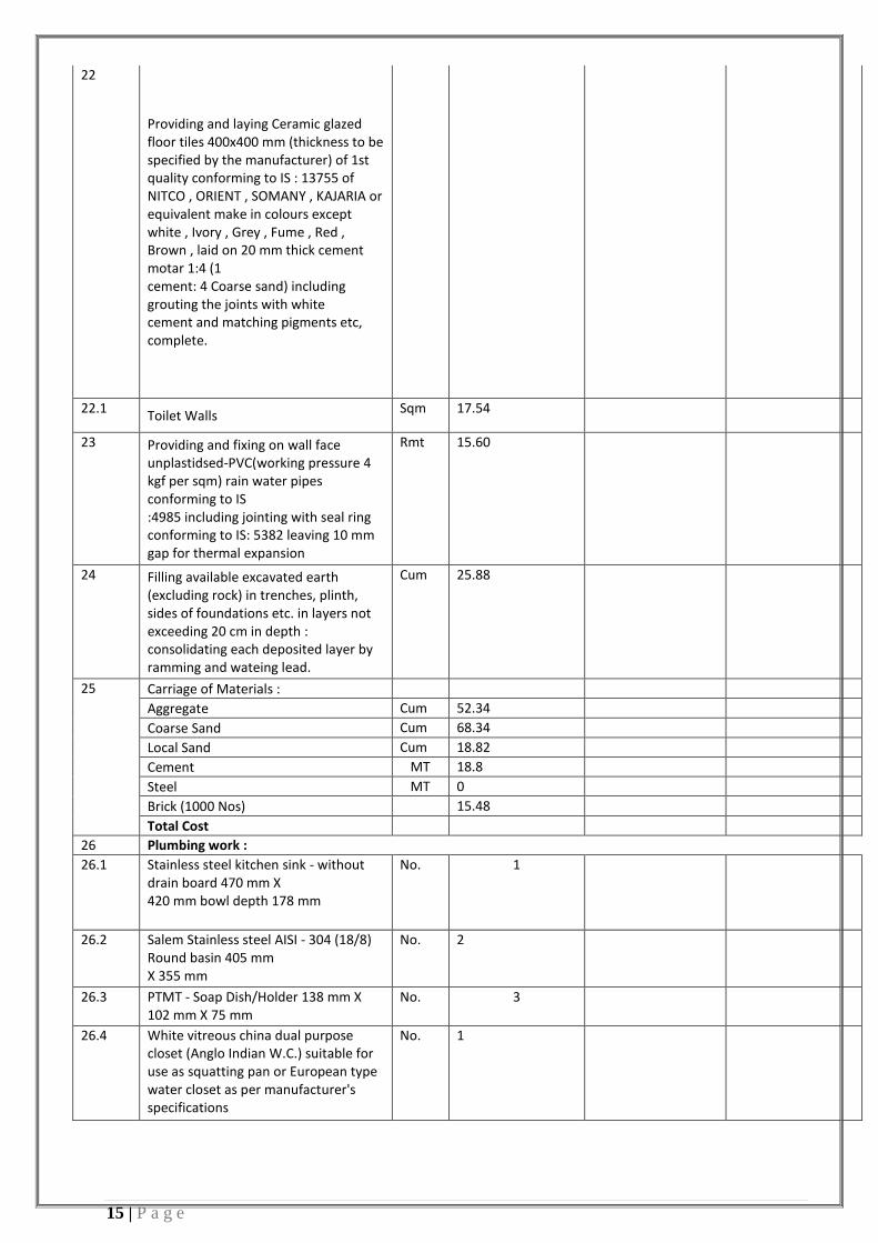
15 | P a g e
22
Providing and laying Ceramic glazed floor tiles 400x400 mm (thickness to be specified by the manufacturer) of 1st quality conforming to IS : 13755 of NITCO , ORIENT , SOMANY , KAJARIA or equivalent make in colours except white , Ivory , Grey , Fume , Red , Brown , laid on 20 mm thick cement motar 1:4 (1 cement: 4 Coarse sand) including grouting the joints with white cement and matching pigments etc, complete.
22.1 Toilet Walls
Sqm 17.54
23 Providing and fixing on wall face unplastidsed-PVC(working pressure 4 kgf per sqm) rain water pipes conforming to IS :4985 including jointing with seal ring conforming to IS: 5382 leaving 10 mm gap for thermal expansion
Rmt 15.60
24 Filling available excavated earth (excluding rock) in trenches, plinth, sides of foundations etc. in layers not exceeding 20 cm in depth : consolidating each deposited layer by ramming and wateing lead.
Cum 25.88
25 Carriage of Materials :
Aggregate Cum 52.34
Coarse Sand Cum 68.34
Local Sand Cum 18.82
Cement MT 18.8
Steel MT 0
Brick (1000 Nos) 15.48
Total Cost
26 Plumbing work :
26.1 Stainless steel kitchen sink - without drain board 470 mm X 420 mm bowl depth 178 mm
No. 1
26.2 Salem Stainless steel AISI - 304 (18/8) Round basin 405 mm X 355 mm
No. 2
26.3 PTMT - Soap Dish/Holder 138 mm X 102 mm X 75 mm
No. 3
26.4 White vitreous china dual purpose closet (Anglo Indian W.C.) suitable for use as squatting pan or European type water closet as per manufacturer's specifications
No. 1

16 | P a g e
26.4.1 White Vitreous china 10 lit. (full flush) capacity controlled low levelflushing cistern with all fittings
No. 1
26.5 C.P.brass toilet paper holder of standard size
No. 3
26.6 PTMT - Towel Rail (600 mm) No. 3
26.7 Providing and fixing Chlorinated Polyvinyl Chloride (CPVC) pipes,having thermal stability for hot & cold water supply, including all CPVC plain & brass threaded fittings, including fixing the pipe with clamps at 1.00 m spacing. This includes jointing of pipes & fittings with one step CPVC solvent cement and testing of joints complete as per direction of Engineer in Charge.
26.7.1 15 mm nominal outer dia Pipes M 25
26.7.2 25 mm nominal outer dia Pipes M 25
26.7.3 32 mm nominal outer dia Pipes M 15
26.8 uPVC pipes (working pressure 4 kg / cm2 ) Single socketed pipe
26.8.1 75 mm M 30
26.8.2 110 mm M 30
26.9 15 mm C.P. brass tap with elbow operation lever
No. 4
26.1 Gunmetal non-return valve-horizontal (screwed end) 25 mm dia
No. 1
26.11 Providing and placing on terrace (at all floor levels) polyethylene water storage tank, ISI : 12701 marked, with cover and suitable locking arrangement and making necessary holes for inlet, outlet and overflow pipes but without fittings and the base support for tank.
Lit 2000
26.12 Brass full way valve with C.I. wheel (screwed end) 40 mm dia
No 1
26.13 Gunmetal non-return valve-horizontal (screwed end) 25 mm dia
No 1

17 | P a g e
26.14 Constructing brick masonry chamber for underground C.I. inspection chamber and bends with bricks in cement mortar 1:4 (1 cement : 4 coarse sand) C.I. cover with frame (light duty) 455x610 mm internal dimensions, total weight of cover with frame to be not less than 38kg (weight of cover 23 kg and weight of frame 15 kg), R.C.C. top slab with 1:2:4 mix (1 cement : 2 coarse sand : 4 graded stone aggregate 20 mm nominal size), foundation concrete 1:5:10 (1 cement : 5 fine sand : 10 graded stone aggregate 40 mm nominal size), inside plastering 12 mm thick with cement mortar 1:3 (1 cement : 3 coarse sand), finished smooth with a floating coat of neat cement on walls and bed concrete etc. complete as per standard design : With common burnt clay F.P.S. (non modular) bricks of class designation 7.5
No 1
26.15 Providing and fixing square-mouth S.W. gully trap class SP-1 complete with C.I. grating brick masonry chamber with water tight C.I. cover with frame of 300 x300 mm size (inside) the weight of cover to be not less than 4.50 kg and frame to be not less than 2.70 kg as per standard design With common burnt clay F.P.S. (non modular) bricks of class designation 7.5
No 1
26.16 Circular shape 560 mm dia precast R.C.C. manhole cover with frame - H.D. – 35
No 1
Total Cost of Sanitary items
Total Cost

18 | P a g e
1.5 BOQ For Electrical Components For Pump-house
Sl.No Description Unit Quantity Rate (INR)
Amount (INR)
1 EARTHING
1.1
Neutral Earthing - Earthing with Copper earth plate 600mmx600mmx3mm thick including accesseries, and providing masonary enclosure with cover plate having locking arrangement and watering pipe of 2.7m long etc with charcoal/coke and salt as required.
No 2
1.2 Body Earthing - Earthing with Gi earth pipe 4.5m long, 40mm dia including accesseries, and providing masonary enclosure with cover plate having locking arrangement and watering pipe etc with charcoal/coke and salt as required.
No 2
2 LT PANEL BOARD (Indoor type)
2.1
Supplying and fixing following way prewired SP&N MCB distribution board of steel sheet for 240 volts on surface/ recess complete with loose wire box, terminal connectors for all incoming and outgoing circuits, duly prewired with suitable size FRLS PVC insulated copper conductor up to terminal blocks, tinned copper bus bar, neutral link, earth bar, din bar, detachable gland plate, interconnections, powder painted including earthing etc. as required. (But without MCB/ RCCB/ Isolator) 2 + 8 way/10 way, Double door
No 1
2 MCCB DISTRIBUTION BOARDS
Providing and fixing 100A rating and 16KA breaking capacity and pole TP MCCB in existing cubicle panel board including drilling holes in cubicle panel, making connections, ets as required.
No 1
2 MINIATURE CIRCUIT BREAKERS
Supplying and fixing 32A, triple pole and neutral, 415V, "C" curve, miniature circuit breaker for inductive load of triple pole and neutral in the existing MCB DB complete with connections, testing and commitioning etc as required.
No 2
2 MINIATURE CIRCUIT BREAKERS
Supplying and fixing 32A, single pole and neutral, 240V, "C" curve, miniature circuit breaker for inductive load of single pole and neutral in the existing MCB DB complete with connections, testing and commitioning etc as required.
No 1

19 | P a g e
3 EARTHING
Body Earthing - Earthing with Gi earth pipe 4.5m long, 40mm dia including accesseries, and providing masonary enclosure with cover plate having locking arrangement and watering pipe etc with charcoal/coke and salt as required.
No 2
3 DISTRIBUTION BOARD
3.1
Supply and fixing 4+12 way, single door, horizontal type thee pole and neutral, sheet steel, MCB DB, 415V, on surface/recess, complete with tinned copper bus bar, nuetral bus bar, earth bar, din bar, interconnections, powdered painted including earthing etc as required. (but without MCB/RCCB/isolators)
M 1
3.2 EARTHING
Body Earthing - Earthing with Gi earth pipe 4.5m long, 40mm dia including accesseries, and providing masonary enclosure with cover plate having locking arrangement and watering pipe etc with charcoal/coke and salt as required.
No 2
4 CABLES
Supply of LT UG cable having Copper conductor PVC insulated,Sheathed ,galvanised steel wire /steel tap armoured cable with PVC outer sheathing 1.1 KV class)
4.1 4Cx16 sq mm + 2x16 sq mm earth wire
M 1
4.2 4Cx10 sq mm + 2x10 sq mm earth wire
M 6.5
4.3 4Cx4 sq mm + 2x4 sq mm earth wire
M 15
4.4 2Cx2.5 sq mm + 1x2.5 sq mm earth wire
M 14
5 LUMINARIES, SOCKETS AND SWITCHES
5.1 120W Gate lamp with fitting
No 2
5.2 40W flourescent lamp
No 4
5.3 70W MH Lamp for site lighting
No 4
5.4 Single switched socket with multi purpose
No 2
5.5 Switches
No 6
6 POWER CONNECTION
Main power supply connection from the
nearest BSEB source to SPS premises i/c
Poles,cables,HT jointing Kit and all
Job 1

20 | P a g e
associated works as per Technical
specifications and direction of EIC.up to
Punping Station including providing of
poles, wires, cables etc. 7 Transformer of required capacity
including H.T. panels-(incoming
&Outgoing) with all associated works as
per Technical specifications and
direction of EIC.
No 1
8 Main L.T. Panel including incoming
Panel, bus coupler, APFC Panel Load
Distribution Panel and all associated
accessories.
Job 1
Total Cost
1.6 BOQ FOR DG SET
Sl.No Description Unit Quantity Rate (INR)
Amount (INR)
1 DIESEL GENERATOR 50 KVA
1.1 50 KVA, 40KW, 415V, 50 Hz, comprising of Perkins Engine Coupled to Stamford make Alternator, complete with all Standard accessories and ATS with Acoustic enclosure.
No 1
1.2 EARTHING
1.2.1
Neutral Earthing - Earthing with Copper earth plate 600mmx600mmx3mm thick including accesseries, and providing masonary enclosure with cover plate having locking arrangement and watering pipe of 2.7m long etc with charcoal/coke and salt as required.
No 2
1.2.2 Body Earthing - Earthing with Gi earth pipe 4.5m long, 40mm dia including accesseries, and providing masonary enclosure with cover plate having locking arrangement and watering pipe etc with charcoal/coke and salt as required.
No 2
2 LT PANEL BOARD (Indoor type)

21 | P a g e
2.1
Supplying and fixing 4 ways surface/recess mounting, vertical type, 415V, TPN MCB distribution board of sheet steel, dust protected , duly powder painted, inclusive of 200A tinned copper bus bar, common neutral link, earth bar, din bar for mounting MCB's, with provision of 100A TP 16KA MCCB as incommer, interconnection between incomer MCCB and bus bars ( but without MCB,s /MCCB's) as required. (Note : Vertical type MCB TPDB is normally used where 3 phase outlets are required.)
No 1
2.2 MCCB DISTRIBUTION BOARDS
Providing and fixing 100A rating and 16KA breaking capacity and pole TP MCCB in existing cubicle panel board including drilling holes in cubicle panel, making connections, ets as required.
No 1
2.3 MINIATURE CIRCUIT BREAKERS
Supplying and fixing 32A, triple pole and neutral, 415V, "C" curve, miniature circuit breaker for inductive load of triple pole and neutral in the existing MCB DB complete with connections, testing and commitioning etc as required.
No 2
2.4 MINIATURE CIRCUIT BREAKERS
Supplying and fixing 32A, single pole and neutral, 240V, "C" curve, miniature circuit breaker for inductive load of single pole and neutral in the existing MCB DB complete with connections, testing and commitioning etc as required.
No 1
2.5 EARTHING
Body Earthing - Earthing with Gi earth pipe 4.5m long, 40mm dia including accesseries, and providing masonary enclosure with cover plate having locking arrangement and watering pipe etc with charcoal/coke and salt as required.
No 2
3 DISTRIBUTION BOARD

22 | P a g e
3.1
Supply and fixing 4+12 way, single door, horizontal type thee pole and neutral, sheet steel, MCB DB, 415V, on surface/recess, complete with tinned copper bus bar, nuetral bus bar, earth bar, din bar, interconnections, powdered painted including earthing etc as required. (but without MCB/RCCB/isolators)
M 1
3.2 EARTHING
Body Earthing - Earthing with Gi earth pipe 4.5m long, 40mm dia including accesseries, and providing masonary enclosure with cover plate having locking arrangement and watering pipe etc with charcoal/coke and salt as required.
No 2
4 CABLES
Supply of LT UG cable having Copper conductor PVC insulated,Sheathed ,galvanised steel wire /steel tap armoured cable with PVC outer sheathing 1.1 KV class)
4.1 4Cx16 sq mm + 2x16 sq mm earth wire M 1
4.2 4Cx10 sq mm + 2x10 sq mm earth wire M 6.5
4.3 4Cx4 sq mm + 2x4 sq mm earth wire M 15
4.4 2Cx2.5 sq mm + 1x2.5 sq mm earth wire M 14
5 LUMINARIES, SOCKETS AND SWITCHES
5.1 120W Gate lamp with fitting No 2
5.2 40W flourescent lamp No 4
5.3 70W MH Lamp for site lighting No 4
5.4 Single switched socket with multi purpose No 2
5.5 Switches No 6
Total Cost

23 | P a g e
1.7: BOQ for Rising Main Cost
Sl. No. Description of Item Unit Quantity Rate ( INR ) Amount (INR )
1.0
Excavating trenches of required width for pipes cables, etc., including excavation for sockets, and dressing of sides, ramming of bottoms, depth upto 1.5 m including getting out the excavated soil, and then returning the soil as required, in layers not exceeding 20 cm in depth including consolidating each deposited layer by ramming, watering etc., and disposing of surplus excavated soil as directed, within a lead of 50 m.
1.1 0.0 to 1.5 mtr. Depth
do - in all kindes of soil - 100% M 3.92
2.0 Supplying and Filling in plinth with local sand and under floors including , watering, ramming consolidation and dressing complete.
cum 391.50
3.0 Providing and laying S&S Centrifugally Cast (Spun) / Ductile Iron. Pipes conforming to IS : 8329 :DI-K9
3.1 300 M 2900
4 Providing push on joints to Centifugally (Spun) Cast Iron Pipes or Ductile Iron Pipes inculding testing of joints and the cost of rubber gasket (one at every 6m).
4.1 300 Joint 483
5 Providing and laying D.I. specials of class K-12 suitable for push-on jointing as per IS : 9523 :
5.1 Bends-As per BS 4772 code
90 degree (63.5 Kg) Kg 444.5
5.2 Taper-As per BS 4772 code
300x200mm (34.5 Kg) Kg 34.5
5.3 Tee-As per BS 4772 code
300x300x300 mm (79.5 Kg) Kg 79.5

24 | P a g e
6.0 Providing and fixing C.I. sluice valves (with cap) complete with bolts, nuts, rubber insertions etc.(the tail pieces if required will be paid separately)
6.1 300 No 6
7.0 Providing and fixing C.I. sluice valves for Scouring (with cap) complete with bolts, nuts, rubber insertions etc.(the tail pieces if required will be paid separately)
7.1 300 No 3
8.0
Providing & Constructing masonry Chamber 1.5x1.5x1.5 m inside, in brick work in cement mortar 1:3 (1 cement : 3 coarse sand) for valve, with cast insitu RCC slab with necessary reinforcment.The valve chamber shall be plastered with CM 1:4, A levelling coars of M10 shall be provided.The cost is inclusive of excavation , disposal and construction of valve chamber with moduar bricks plasting with cement mortar with all lead and lift etc., as per specification & drawing.
8.1 Sluice valve chambers No 6
8.2 Scour valve chambers No 6
9.0
Providing and constructing of the RCC Thrust Blocks for DI bends including the excavations of soils up to the required depth ,disposal of soils after refilling with selected available earth,providing PCC including cost of labours,materials tools,curing etc., complete as per drawing and as directed by the Engineer (inclusive of cost of steel)
9.1
90 degree No 2
Enter Total pipe length 2900 M
Percentage of CC Road in town 70 %
Percentage of Asphalt Road in town 30 %
10 Dismantling and restoration of roads :

25 | P a g e
10.1
Dismantling of cement concrete pavement (dismantling of cement concrete pavements by mechanical means using pneumatic tools, breaking to pieces not exceeding 0.02 cum in volume and stock pilling at designated locations and disposal of dismantled materials up to a lead of 1000 metres, stacking serviceable and unserviceable material
cum 274.05
Dismantalling of flexible Pavements( dismantling of flexible pavements and disposal of dismantled materials up to a lead of 1000 m, stacking serviceable and unserviseable materials separately)
Bituminous courses by mechanical means cum 39.15
Granular courses by manualmeans cum 456.75
11 Restoration of road as per the specification and as directed by the engineer
11.1 Restoration of CC road
A Compacting original ground supporting subgrade (Loosening of the ground upto a level of 500 mm below the subgrade level, watered, graded and compacted in layers to meet requirement of table 300-2 for subgrade construction.) Rolling with vibratory roller
cum 1305.00
B Wet Mix Macadam - Providing, laying, spreading and compacting graded stone aggregate to wet mix macadam specification including premixing the material with water at OMC in mechanical mix plant carriage of mixed mathod of tipper to site, laying in uniform layers with paver in sub-base/base course on a well prepared surface and compacting with vibratory roller to achieve the desired density complete as per Specification
cum 97.88
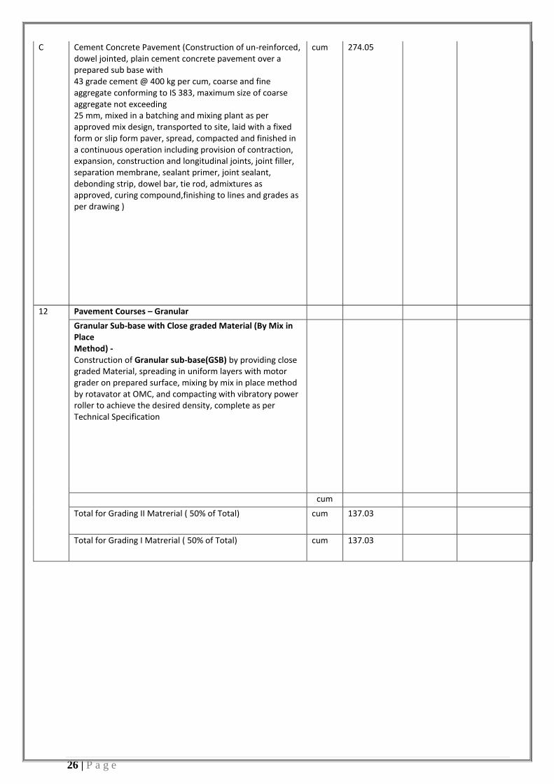
26 | P a g e
C Cement Concrete Pavement (Construction of un-reinforced, dowel jointed, plain cement concrete pavement over a prepared sub base with 43 grade cement @ 400 kg per cum, coarse and fine aggregate conforming to IS 383, maximum size of coarse aggregate not exceeding 25 mm, mixed in a batching and mixing plant as per approved mix design, transported to site, laid with a fixed form or slip form paver, spread, compacted and finished in a continuous operation including provision of contraction, expansion, construction and longitudinal joints, joint filler, separation membrane, sealant primer, joint sealant, debonding strip, dowel bar, tie rod, admixtures as approved, curing compound,finishing to lines and grades as per drawing )
cum 274.05
12 Pavement Courses – Granular
Granular Sub-base with Close graded Material (By Mix in Place Method) - Construction of Granular sub-base(GSB) by providing close graded Material, spreading in uniform layers with motor grader on prepared surface, mixing by mix in place method by rotavator at OMC, and compacting with vibratory power roller to achieve the desired density, complete as per Technical Specification
cum
Total for Grading II Matrerial ( 50% of Total) cum 137.03
Total for Grading I Matrerial ( 50% of Total) cum 137.03

27 | P a g e
B Wet Mix Macadam - Providing, laying, spreading and compacting graded stone aggregate to wet mix macadam specification including premixing the material with water at OMC in mechanical mix plant carriage of mixed mathod of tipper to site, laying in uniform layers with paver in sub-base/base course on a well prepared surface and compacting with vibratory roller to achieve the desired density complete as per Specification
cum 456.75
C Pavement Courses – Bituminous
Prime Coat - Providing and applying primer coat with Bitumen emulsion on prepared surface of granular base including cleaning of road surface and spraying primer at the rate of 0.6kg/sqm using mechnical means complete
sqm 1827.00
Tack Coat - Providing and applying tack coat with Bitumen emulsion using emulsion pressure distributor at the rate of 0.2 kg per sqm on the prepared bituminous/granular surface cleaned with mechancial broom .
sqm 1827.00
Providing and laying Dense graded bituminous macadam with 100- 120 TPH batch HMP producing an average output of 75 tonnes per hour using crushed aggregates of specified grading, premixed with bituminous binder @ 4.0 to 4.5 % by weight of total mix and filler, transporting the hot mix to work site, laying with a hydrostatic paver finisher with sensor control to the required grade, level and alignment, rolling with smooth wheeled, vibratory and tandem rollers to achieve the desired compaction as per MoRTH specifications Clause 507. (Grading II -19mm nominal size)
cum 45.68
Total Cost, Rs
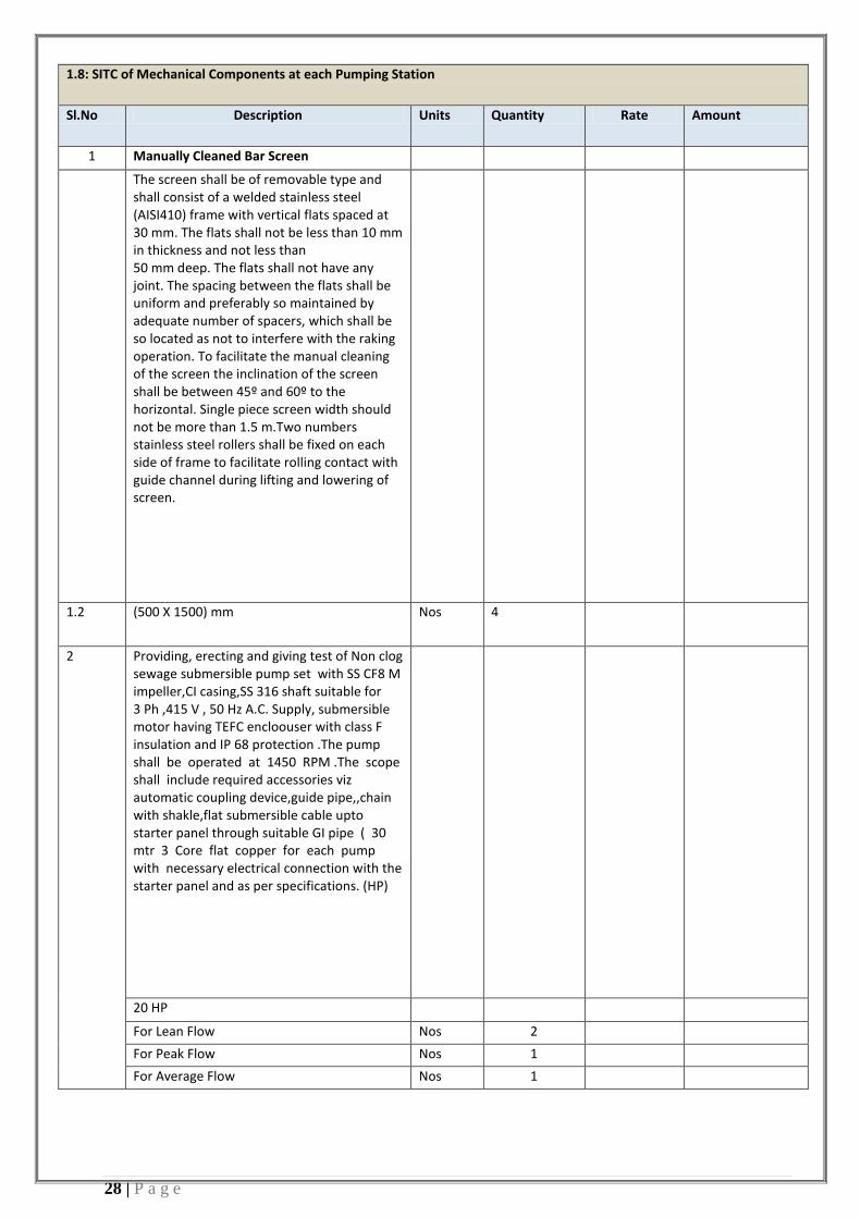
28 | P a g e
1.8: SITC of Mechanical Components at each Pumping Station
Sl.No Description Units Quantity Rate Amount
1 Manually Cleaned Bar Screen
The screen shall be of removable type and shall consist of a welded stainless steel (AISI410) frame with vertical flats spaced at 30 mm. The flats shall not be less than 10 mm in thickness and not less than 50 mm deep. The flats shall not have any joint. The spacing between the flats shall be uniform and preferably so maintained by adequate number of spacers, which shall be so located as not to interfere with the raking operation. To facilitate the manual cleaning of the screen the inclination of the screen shall be between 45º and 60º to the horizontal. Single piece screen width should not be more than 1.5 m.Two numbers stainless steel rollers shall be fixed on each side of frame to facilitate rolling contact with guide channel during lifting and lowering of screen.
1.2 (500 X 1500) mm Nos 4
2 Providing, erecting and giving test of Non clog sewage submersible pump set with SS CF8 M impeller,CI casing,SS 316 shaft suitable for 3 Ph ,415 V , 50 Hz A.C. Supply, submersible motor having TEFC encloouser with class F insulation and IP 68 protection .The pump shall be operated at 1450 RPM .The scope shall include required accessories viz automatic coupling device,guide pipe,,chain with shakle,flat submersible cable upto starter panel through suitable GI pipe ( 30 mtr 3 Core flat copper for each pump with necessary electrical connection with the starter panel and as per specifications. (HP)
20 HP
For Lean Flow Nos 2
For Peak Flow Nos 1
For Average Flow Nos 1

29 | P a g e
3 Providing Supplying erection testing and commissioning of 2 Tonne capacity Mobile Crane
3 1 T Capacity for 7 m lift. Nos 1
Total Cost, Rs

30 | P a g e
2.0: I&D Nallah-II_Salempur Nallah
Item Description Quantity Total Amount
2.1) Drain construction Cost Detailes are attached
2.2) Outfall Structure cost Detailes are attached
2.3) Generator Room Cost Detailes are attached
2.4) Operator Quarter Cost Detailes are attached
2.5) Elctrical Component Cost Detailes are attached
2.6)DG Cost Detailes are attached
2.7) Rising Main Cost Detailes are attached
2.8)Pump and screen cost Detailes are attached
Total Cost, Rs

31 | P a g e
2.1: BOQ for Drain Construction Cost
Existing Drain Size Proposed Drain Size
SI. No.
Name of Drains/ Nallah falling in Ganga River
Length of Drain (m) to be constructed
Velocity (m/sec)
Effective flow area
Flow (MLD)
Width Height Rate Per RM
Drain Cost for Total length
Width Height I&D Remark
1 Salempur Nala 100 0.18 10% 2.39 1.00 1.50 1.5 1.50 Pumping TO STP

32 | P a g e
2.2: BOQ for Outfall Structures
Sl no.
Description of Item Unit Quantity Rate (INR)
Amount (INR)
1 Earth work excavation in foundation trenches or drains including dressing of sides and ramming of bottoms, lift as follows, including getting out the excavated soil and disposal of surplus excavated soil as directed, with all lead and lift complete as per the specification and as directed by the Engineer. All kinds of soils
1.1.1 Upto1.50m depth cum 51.73
1.5 m to 3 m cum 65.10
2 Sand filling upto 300mm in Plinth including watering and compacting in layers of 150 mm thick as per specifications and as directed by the Engineer.
cum 10.35
3 Providing and laying in position cement concrete of specified grade excluding the cost of centring and shuttering - all work upto plinth level in 1:3:6 (1 Cement : 3 coarse sand : 6 granded stone)
Cum 8.27
4 Providing and laying in position machine batched, machine mixed, and machine vibrated design mix cement concrete of specified grade for reinforced cement concrete structural elements, excluding the cost of centering, shuttering, finishing and reinforcement, M-20 grade reinforced cement concrete.
Cum 29.53
5 Centring and Shuttering including strutting, propping etc. and remov
sqm 108.42
6 Reinforcement for R. C. C work including straightening, cutting, bending, placing in position and binding all complete. Thermo - Mechanically Treated bars TMTC - 500 ( Quantity at 90 kg/cum)
Kg 2657.70
7 Carriage of the following materials from quarry to work site including loading, unloading and staking at work site as per specification & direction of E/I.
Aggregate Cum 54.29
Sand Cum 27.14
Cement MT 24.1074
Steel MT 2.6577

33 | P a g e
8 Wrought iron and mild steel welded work (using angles, square bars, tees and channel grills, grating frames, gates and tree guards of any size and design etc. including cost of screens and welding rods or bolts and nuts complete fixed in position but without the cost of excavation and concrete for fixing which will be paid separately
Kg 240.00
Erection of gates (a) 30% item NO- 8 Kg 240
8.0 Centring and Shuttering including strutting, propping etc. and removal of form for Roof slab
8.1 For roof slab Sqm 18
8.2 Weather shade,Chajjas, corbels etc. including edges Sqm 1.2
9.0 Reinforcement for R. C. C work including straightening, cutting, bending, placing in position and binding all complete. Thermo - Mechanically Treated bars
9.00
steel quantities kg 810
10.0 Brick work with bricks of class designation 100A in foundations and plinth in :Extra for Brick work in superstructure above plinth level upto floor V cum
Cum 5.87
11.0 12 mm Cement plaster in course sand in 1:3 (1 cement : 3 coarse sand) (for Internal walls)
Sqm 25.50
12.0 12 mm Cement plaster in course sand in 1:3 (1 cement : 3 coarse sand) (for ceiling)
18.00
13.0 20 mm Cement plaster in course sand in 1:3 (1 cement : 3 coarse sand) (for External walls)
Sqm 26.40
14.0 Wall painting with plastic emulsion paint of approved brand and man
Sqm 25.50
15.0 Wall painting with plastic emulsion paint of approved brand and man
Sqm 25.50
16.0 Appying one coat of cement primer of approved brand and manufacture on wall surface (for External walls)
Sqm 18.00
17.0 Providing wood work in frames of door, window clerestory windows and other frames, wrought framed and fixed in position in local wood for Door
Cum 26.40

34 | P a g e
18.0 Providing and fixing paneled or paneled and glazed shutters for doors, windows and clerestory windows including black enameled MS butt hinges with necessary screws excluding panelling which will be paid for separately - 30 mm thick
0.50
For Doors Sqm 1.8
19.0 Providing and fixing glazing in aluminium door, window V shutters and partition etc with PVC / neoprene gasket etc. complete as per the architectural drawings and the directions of Engineer incharge. (Cost of aluminium snap bading shall be paid in basic item). With glass pans of 5.50 mm thickness (Weight not less than 13.75 kg/sqm)
Sqm 0.50
20.0 Providing and laying Ceramic glazed floor tiles (400x400) mm (thickness to be specified by the manufacturer) of 1st quality conforming to IS:13755 of NITCO, ORIENT, SOMANY, KAJARIA or equivalent make in colours such as White, Ivory, Grey, Fume, Red, Brown, laid on 20 mm thick cement mortar 1:4 (1 cement : 4 coarse sand) including grouting the joints with white cement and matching pigments etc, complete.
18.00
Total Cost, Rs

35 | P a g e
2.3 BOQ of Generator Room
Sl. No. Item description Unit Quantity Rate (INR)
Amount (INR)
Earth work
1.0 Earthwork in excavation in foundation trenches or drains (not exceeding 1.5 m width or 10 sqm on plan) including dressing of sides and ramming of bottoms, lift upto 1.5 m including getting out the excavated soil and disposals of surplus excavated soil as directed, within a lead of 50 m. (For all kinds of soil)
1.1 From 0 m to 1.5 m Cum 22.54
1.2 From 1.5 m to 3 m Cum 1.35
2.0 Supplying and Filling on plinth with local sand and under floors including watering, ramming consolidating and dressing complete. For Generater room
Cum 7.20
3.0 Providing and laying in position cement concrete of specified grade excluding the cost of centring and shuttering - all work upto plinth level in 1:3:6 (1 Cement : 3 coarse sand : 6 granded stone upto 20 mm nominal size)
Cum 7.33
4.0 Providing and laying in position machine batched, machine mixed, and machine vibrated design mix cement concrete of specified grade for reinforced cement concrete structural elements, excluding the cost of centering, shuttering, finishing and reinforcement, M-20 grade reinforced cement concrete.
4.1 For Footings Cum 1.44
4.2 Column below GL up to Plinth Cum 0.26
4.3 Plinth beams Cum 1.61
4.4 For columns above Ground levels Cum 0.87
4.5 Lintel beams Cum 1.43
4.6 Roof Beams Cum 1.33
4.7 For roof slab Cum 4.32
4.8 For Sunshades over Door & Windows : Cum 0.23
5.0 Centring and Shuttering including strutting, propping etc. and removal of form for
5.1 For footing – F Sqm 4.80
5.2 Column upto GL – C Sqm 4.60
5.3 Plinth beams : Sqm 14.00
6.0 Centring and Shuttering including strutting, propping etc. and removal of form for
Sqm

36 | P a g e
6.1 Lintel beams Sqm 12.4
6.2 Roof beams Sqm 12.4
7.0 Centring and Shuttering including strutting, propping etc. and removal of form for
Column Sqm 15.09
8.0 Centring and Shuttering including strutting, propping etc. and removal of form for Roof slab
8.1 For roof slab Sqm 24
8.2 Weather shade,Chajjas, corbels etc. including edges
Sqm 4.13
9.0 Reinforcement for R. C. C work including straightening, cutting, bending, placing in position and binding all complete. Thermo - Mechanically Treated bars
steel quantities MT 1.34
10.0 Brick work with bricks of class designation 100A in foundations and plinth in :Extra for Brick work in superstructure above plinth level upto floor V cum
Cum 17.53
11.0 12 mm Cement plaster in course sand in 1:3 (1 cement : 3 coarse sand) (for Internal walls)
Sqm 64.48
12.0 12 mm Cement plaster in course sand in 1:3 (1 cement : 3 coarse sand) (for ceiling)
Generator room Sqm 24
13.0 20 mm Cement plaster in course sand in 1:3 (1 cement : 3 coarse sand) (for External walls)
Sqm 89.54
14.0 Wall painting with plastic emulsion paint of approved brand and manufacture to give an even shade : Two or more coats on new work (for Internal walls)
Sqm 64.48
15.0 Wall painting with plastic emulsion paint of approved brand and manufacture to give an even shade : Two or more coats on new work (for ceiling)
Sqm 24.00
16.0 Appying one coat of cement primer of approved brand and manufacture on wall surface (for External walls)
Sqm 89.54
17.0 Providing wood work in frames of door, window clerestory windows and other frames, wrought framed and fixed in position in local wood for Door
Cum 0.16
18.0 Providing and fixing paneled or paneled and glazed shutters for doors, windows and clerestory windows including black enameled MS butt hinges with necessary screws excluding panelling which will be paid for separately - 30 mm thick
For Doors Sqm 4.2

37 | P a g e
19.0 Providing and fixing glazing in aluminium door, window V shutters and partition etc with PVC / neoprene gasket etc. complete as per the architectural drawings and the directions of Engineer incharge. (Cost of aluminium snap bading shall be paid in basic item). With glass pans of 5.50 mm thickness (Weight not less than 13.75 kg/sqm)
Sqm 4.32
20.0
Providing and laying Ceramic glazed floor tiles (400x400) mm (thickness to be specified by the manufacturer) of 1st quality conforming to IS:13755 of NITCO, ORIENT, SOMANY, KAJARIA or equivalent make in colours such as White, Ivory, Grey, Fume, Red, Brown, laid on 20 mm thick cement mortar 1:4 (1 cement : 4 coarse sand) including grouting the joints with white cement and matching pigments etc, complete.
Generater room Sqm 24
21.0 Cement plaster skirting (upto 30 cm height) with cement mortar 1:3 (1 cement : 3 coarse sand) finished with a floating coat of neat cement. 18 mm thick
Sqm 2.70
22.0
Providing and laying in situ five course water proofing treatment with glass fibre tissue reinforced bitumen over roof consisting of first coat of bitumen primer @ 0.40 kg per sqm, 2nd and 4th courses of bonding material 1.60 kg per sqm which shall consist of blown type bitumen of grade 85/25 conforming to IS : 702, third layer of glass fibre tissue course as specified, fifth, the top most layer of stone grit 6 mm and down size or pea-seized gravel sprad @ 6 dm3 per sqm including preparation of surface excluding grading for slope etc. compete.
Sqm 24.00
23.0 Providing and fixing on wall face unplastidsed-PVC (working pressure 4 kgf per sqm) rain water pipes conforming to IS :4985 including jointing with seal ring conforming to IS: 5382 leaving 10 mm gap for thermal expansion. 110 mm diameter
M 13.50

38 | P a g e
24.0 Filling available excavated earth (excluding rock) in trenches, plinth, sides of foundations etc. in layers not exceeding 20 cm in depth : consolidating each deposited layer by ramming and wateing lead.
Cum 14.86
25.0 Carriage of Materials :
Aggregate Cum 16.66
Coarse Sand Cum 31.07
Local Sand Cum 7.2
Cement MT 6.01
Steel MT 0.14
Brick (1000 Nos) 8.59
Total Cost

39 | P a g e
2.4 BOQ of Operators Quarter
Sl. No Item description Unit Quantity Rate (INR)
Amount (INR)
1
Earthwork in excavation in foundation trenches or drains (not exceeding 1.5 m width or 10 sqm on plan) including dressing of sides and ramming of bottoms, lift upto 1.5 m including getting out the excavated soil and disposals of surplus excavated soil as directed, within a lead of 50 m. (For all kinds of soil)
1.1 From 0 m to 1.5 m Cum 36.72
1.2 From 1.5 m to 3 m Cum 3.24
2 Supplying and Filling on plinth with local sand and under floors including watering, ramming consolidating and dressing complete.
Cum 18.82
3 Providing and laying in position cement concrete of specified grade excluding the cost of centring and shuttering - all work upto plinth level in 1:3:6 (1 Cement : 3 coarse sand : 6 granded stone)
Cum 23.51
4
Providing and laying in position machine batched, machine mixed, and machine vibrated design mix cement concrete of specified grade for reinforced cement concrete structural elements, excluding the cost of centering, shuttering, finishing and reinforcement, M-20 grade reinforced cement concrete.
4.1 For Columnn Footing Cum 4.48
4.2 For Column below GL up to plinth Cum 0.74
4.3 For Plinth beams-PB Cum 5.08
4.4 For columns above GL Cum 2.45
4.5 For lintel beams Cum 2.04
4.6 For Roof beams Cum 3.59
4.7 For Roof slab Cum 12.03
4.8 For Parapet Cum 2.39
5
Providing and laying in position machine batched, machine mixed, and machine vibrated design mix cement concrete of specified grade for reinforced cement concrete structural elements, excluding the cost of centering, shuttering, finishing and reinforcement, M-20 grade reinforced cement concrete.

40 | P a g e
5.1 Sunshade over Windows Cum 0.89
5.2 For Lofts & Racks Cum 1.88
6 Centring and Shuttering including strutting, propping etc. and removal of form for
6.1 For Columnn Footing (C1 F1) Sqm 10.8
6.2 For Column below GL up to plinth Sqm 51.36
6.3 For Plinth beams-PB Sqm 41.65
6.4 For columns above GL Sqm 42.66
6.5 For lintel beams Sqm 23.43
6.6 For Roof beams Sqm 30.97
6.7 For Roof slab Sqm 131.94
6.8 For Parapet Sqm 4.9
7 Reinforcement for R. C. C work including straightening, cutting, bending, placing in position and binding all complete. Thermo - Mechanically Treated bars
MT 4.14
8 Brick work with bricks of class designation 100A in foundations and plinth in :Extra for Brick work in superstructure above plinth level upto floor V cum
Cum 31.58
9 12 mm Cement plaster in course sand in 1:3 (1 cement : 3 coarse sand) (for Internal walls)
Sqm 167.68
10 12 mm Cement plaster in course sand in 1:3 (1 cement : 3 coarse sand) (for ceiling)
Sqm 58.41
11 20 mm Cement plaster in course sand in 1:3 (1 cement : 3 coarse sand) (for External walls)
Sqm 147.88
12 Wall painting with plastic emulsion paint of approved brand and
Sqm 226.09
13 Appying one coat of cement primer of approved brand and manufacture on wall surface (for External walls)
Sqm 191.98
14 Providing wood work in frames of door, window clerestory windows and other frames, wrought framed and fixed in position in local wood
Cum 0.50
15
Providing and fixing paneled or paneled and glazed shutters for doors, windows and clerestory windows including black enameled MS butt hinges with necessary screws excluding panelling which will be paid for separately - 30 mm thick
Sqm 6.93

41 | P a g e
16
Providing and fixing glazing in aluminium door, window ventilator shutters and partition etc with PVC / neoprene gasket etc. complete as per the architectural drawings and the directions of Engineer incharge. (Cost of aluminium snap bading shall be paid in basic item). With glass pans of 5.50 mm thickness (Weight not less than 13.75 kg/sqm)
16.1 For Windows Sqm 8.28
16.2 For Ventilators Sqm 0.72
17 Providing and fabricating and fixing of M S grill for window protection etc ,. As per specification, drawing and as directed by the engineer
For Windows & Ventilators Kg 9
18
Providing and laying in situ five course water proofing treatment with glass fibre tissue reinforced bitumen over roof consisting of first coat of bitumen primer @ 0.40 kg per sqm, 2nd and 4th courses of bonding material 1.60 kg per sqm which shall consist of blown type bitumen of grade 85/25 conforming to IS : 702, third layer of glass fibre tissue course as specified, fifth, the top most layer of stone grit 6 mm and down size or pea-seized gravel sprad @ 6 dm3 per sqm including preparation of surface excluding grading for slope etc. compete.
18.1 Slope concrete Sqm 74.92
19
Providing and laying Ceramic glazed floor tiles 400x400 mm (thickness to be specified by the manufacturer) of 1 st quality conforming to IS : 13755 of NITCO , ORIENT , SOMANY , KAJARIA or equivalent make in colours such as white , Ivory , Grey , Fume , Red , Brown , laid on 20 mm thick cement motar 1:4 (1 cement: 4 Coarse sand) including grouting the joints with white cement and matching pigments etc, complete.
Total quantity 58.41

42 | P a g e
20
Providing and fixing first quality ceramic glazed wall tiles conforming to IS 15622 ( thickness to be specified by the manufacturer) of approved maike in all colours shades except burgundy, bottle green, black of any size as approved by engineer incharge in skirting risers of steps and dados over 12 mm thick bed of cement mortar (1:3) and jointing with grey cement slurry at 3.3 kg per sqm including pointing in white cement mixed with pigment of matching shade complete
Total quantity Rmt 55.67
21
Providing and laying Ceramic glazed floor tiles 400x400 mm (thickness to be specified by the manufacturer) of 1st quality conforming to IS : 13755 of NITCO , ORIENT , SOMANY , KAJARIA or equivalent make in colours except white , Ivory , Grey , Fume , Red , Brown , laid on 20 mm thick cement motar 1:4 (1 cement: 4 Coarse sand) including grouting the joints with white cement and matching pigments etc, complete.
21.1 Toilet Sqm 5.85
22
Providing and laying Ceramic glazed floor tiles 400x400 mm (thickness to be specified by the manufacturer) of 1st quality conforming to IS : 13755 of NITCO , ORIENT , SOMANY , KAJARIA or equivalent make in colours except white , Ivory , Grey , Fume , Red , Brown , laid on 20 mm thick cement motar 1:4 (1 cement: 4 Coarse sand) including grouting the joints with white cement and matching pigments etc, complete.
22.1 Toilet Walls Sqm 17.54
23 Providing and fixing on wall face unplastidsed-PVC(working pressure 4 kgf per sqm) rain water pipes conforming to IS :4985 including jointing with seal ring conforming to IS: 5382 leaving 10 mm gap for thermal expansion
Rmt 15.60

43 | P a g e
24
Filling available excavated earth (excluding rock) in trenches, plinth, sides of foundations etc. in layers not exceeding 20 cm in depth : consolidating each deposited layer by ramming and wateing lead.
Cum 25.88
25 Carriage of Materials :
Aggregate Cum 52.34
Coarse Sand Cum 68.34
Local Sand Cum 18.82
Cement MT 18.8
Steel MT 0
Brick (1000 Nos) 15.48
Total Cost
26 Plumbing work :
26.1 Stainless steel kitchen sink - without drain board 470 mm X 420 mm bowl depth 178 mm
No. 1
26.2 Salem Stainless steel AISI - 304 (18/8) Round basin 405 mm X 355 mm
No. 2
26.3 PTMT - Soap Dish/Holder 138 mm X 102 mm X 75 mm
No. 3
26.4 White vitreous china dual purpose closet (Anglo Indian W.C.) suitable for use as squatting pan or European type water closet as per manufacturer's specifications
No. 1
26.4.1 White Vitreous china 10 lit. (full flush) capacity controlled low levelflushing cistern with all fittings
No. 1
26.5 C.P.brass toilet paper holder of standard size
No. 3
26.6 PTMT - Towel Rail (600 mm) No. 3
26.7
Providing and fixing Chlorinated Polyvinyl Chloride (CPVC) pipes,having thermal stability for hot & cold water supply, including all CPVC plain & brass threaded fittings, including fixing the pipe with clamps at 1.00 m spacing. This includes jointing of pipes & fittings with one step CPVC solvent cement and testing of joints complete as per direction of Engineer in Charge.
26.7.1 15 mm nominal outer dia Pipes M 25
26.7.2 25 mm nominal outer dia Pipes M 25
26.7.3 32 mm nominal outer dia Pipes M 15
26.8 uPVC pipes (working pressure 4 kg / cm2 ) Single socketed pipe
26.8.1 75 mm M 30
26.8.2 110 mm M 30
26.9 15 mm C.P. brass tap with elbow operation lever
No. 4

44 | P a g e
26.1 Gunmetal non-return valve-horizontal (screwed end) 25 mm dia
No. 1
26.11
Providing and placing on terrace (at all floor levels) polyethylene water storage tank, ISI : 12701 marked, with cover and suitable locking arrangement and making necessary holes for inlet, outlet and overflow pipes but without fittings and the base support for tank.
Lit 2000
26.1 Brass full way valve with C.I. wheel (screwed end) 40 mm dia
No 1
26.13 Gunmetal non-return valve-horizontal (screwed end) 25 mm dia
No 1
26.14
Constructing brick masonry chamber for underground C.I. inspection chamber and bends with bricks in cement mortar 1:4 (1 cement : 4 coarse sand) C.I. cover with frame (light duty) 455x610 mm internal dimensions, total weight of cover with frame to be not less than 38kg (weight of cover 23 kg and weight of frame 15 kg), R.C.C. top slab with 1:2:4 mix (1 cement : 2 coarse sand : 4 graded stone aggregate 20 mm nominal size), foundation concrete 1:5:10 (1 cement : 5 fine sand : 10 graded stone aggregate 40 mm nominal size), inside plastering 12 mm thick with cement mortar 1:3 (1 cement : 3 coarse sand), finished smooth with a floating coat of neat cement on walls and bed concrete etc. complete as per standard design : With common burnt clay F.P.S. (non modular) bricks of class designation 7.5
No 1
26.15
Providing and fixing square-mouth S.W. gully trap class SP-1 complete with C.I. grating brick masonry chamber with water tight C.I. cover with frame of 300 x300 mm size (inside) the weight of cover to be not less than 4.50 kg and frame to be not less than 2.70 kg as per standard design With common burnt clay F.P.S. (non modular) bricks of class designation 7.5
No 1

45 | P a g e
26.2 Circular shape 560 mm dia precast R.C.C. manhole cover with frame - H.D. – 35
No 1
Total Cost of Sanitary items
Total Cost
2.5 BOQ For Electrical Components For Pump-house
Sl.No Description Unit Quantity Rate (INR)
Amount (INR)
1 EARTHING
1.1 Neutral Earthing - Earthing with Copper earth plate 600mmx600mmx3mm thick including accesseries, and providing masonary enclosure with cover plate having locking arrangement and watering pipe of 2.7m long etc with charcoal/coke and salt as required.
No 2
1.2 Body Earthing - Earthing with Gi earth pipe 4.5m long, 40mm dia including accesseries, and providing masonary enclosure with cover plate having locking arrangement and watering pipe etc with charcoal/coke and salt as required.
No 2
2 LT PANEL BOARD (Indoor type)
2.1 Supplying and fixing following way prewired SP&N MCB distribution board of steel sheet for 240 volts on surface/ recess complete with loose wire box, terminal connectors for all incoming and outgoing circuits, duly prewired with suitable size FRLS PVC insulated copper conductor up to terminal blocks, tinned copper bus bar, neutral link, earth bar, din bar, detachable gland plate, interconnections, powder painted including earthing etc. as required. (But without MCB/ RCCB/ Isolator) 2 + 8 way/10 way, Double door
No 1
2.2 MCCB DISTRIBUTION BOARDS
Providing and fixing 100A rating and 16KA breaking capacity and pole TP MCCB in existing cubicle panel board including drilling holes in cubicle panel, making connections, ets as required.
No 1
2.3 MINIATURE CIRCUIT BREAKERS

46 | P a g e
Supplying and fixing 32A, triple pole and neutral, 415V, "C" curve, miniature circuit breaker for inductive load of triple pole and neutral in the existing MCB DB complete with connections, testing and commitioning etc as required.
No 2
2.4 MINIATURE CIRCUIT BREAKERS
Supplying and fixing 32A, single pole and neutral, 240V, "C" curve, miniature circuit breaker for inductive load of single pole and neutral in the existing MCB DB complete with connections, testing and commitioning etc as required.
No 1
2.5 EARTHING
Body Earthing - Earthing with Gi earth pipe 4.5m long, 40mm dia including accesseries, and providing masonary enclosure with cover plate having locking arrangement and watering pipe etc with charcoal/coke and salt as required.
No 2
3 DISTRIBUTION BOARD
3.1 Supply and fixing 4+12 way, single door, horizontal type thee pole and neutral, sheet steel, MCB DB, 415V, on surface/recess, complete with tinned copper bus bar, nuetral bus bar, earth bar, din bar, interconnections, powdered painted including earthing etc as required. (but without MCB/RCCB/isolators)
M 1
3.2 EARTHING
Body Earthing - Earthing with Gi earth pipe 4.5m long, 40mm dia including accesseries, and providing masonary enclosure with cover plate having locking arrangement and watering pipe etc with charcoal/coke and salt as required.
No 2
4 CABLES
Supply of LT UG cable having Copper conductor PVC insulated,Sheathed ,galvanised steel wire /steel tap armoured cable with PVC outer sheathing 1.1 KV class)
4.1 4Cx16 sq mm + 2x16 sq mm earth wire M 1
4.2 4Cx10 sq mm + 2x10 sq mm earth wire M 6.5
4.3 4Cx4 sq mm + 2x4 sq mm earth wire M 15
4.4 2Cx2.5 sq mm + 1x2.5 sq mm earth wire M 14
5 LUMINARIES, SOCKETS AND SWITCHES
5.1 120W Gate lamp with fitting No 2
5.2 40W flourescent lamp No 4
5.3 70W MH Lamp for site lighting No 4
5.4 Single switched socket with multi purpose No 2
5.5 Switches No 6
6 POWER CONNECTION
Main power supply connection
from the nearest BSEB source to
SPS premises i/c Poles,cables,HT
Job 1

47 | P a g e
jointing Kit and all associated
works as per Technical
specifications and direction of
EIC.up to Punping Station
including providing of poles, wires,
cables etc. 7 Transformer of required capacity
including H.T. panels-(incoming
&Outgoing) with all associated
works as per Technical
specifications and direction of EIC.
No 1
8 Main L.T. Panel including
incoming Panel, bus coupler, APFC
Panel Load Distribution Panel and
all associated accessories.
Job 1
Total Cost
2.6 Cost estimate For DG SET
Sl.No Description Unit Quantity Rate (INR)
Amount (INR)
Remarks
1 DIESEL GENERATOR 50 KVA
1.1 50 KVA, 40KW, 415V, 50 Hz, comprising of Perkins Engine Coupled to Stamford make Alternator, complete with all Standard accessories and ATS with Acoustic enclosure.
No 1
1 EARTHING
1.2.1 Neutral Earthing - Earthing with Copper earth plate 600mmx600mmx3mm thick including accesseries, and providing masonary enclosure with cover plate having locking arrangement and watering pipe of 2.7m long etc with charcoal/coke and salt as required.
No 2
1.2.2 Body Earthing - Earthing with Gi earth pipe 4.5m long, 40mm dia including accesseries, and providing masonary enclosure with cover plate having locking arrangement and watering pipe etc with charcoal/coke and salt as required.
No 2
2 LT PANEL BOARD (Indoor type)

48 | P a g e
2.1
Supplying and fixing 4 ways surface/recess mounting, vertical type, 415V, TPN MCB distribution board of sheet steel, dust protected , duly powder painted, inclusive of 200A tinned copper bus bar, common neutral link, earth bar, din bar for mounting MCB's, with provision of 100A TP 16KA MCCB as incommer, interconnection between incomer MCCB and bus bars ( but without MCB,s /MCCB's) as required. (Note : Vertical type MCB TPDB is normally used where 3 phase outlets are required.)
No 1
2 MCCB DISTRIBUTION BOARDS
Providing and fixing 100A rating and 16KA breaking capacity and pole TP MCCB in existing cubicle panel board including drilling holes in cubicle panel, making connections, ets as required.
No 1
2 MINIATURE CIRCUIT BREAKERS
Supplying and fixing 32A, triple pole and neutral, 415V, "C" curve, miniature circuit breaker for inductive load of triple pole and neutral in the existing MCB DB complete with connections, testing and commitioning etc as required.
No 2
2 MINIATURE CIRCUIT BREAKERS
Supplying and fixing 32A, single pole and neutral, 240V, "C" curve, miniature circuit breaker for inductive load of single pole and neutral in the existing MCB DB complete with connections, testing and commitioning etc as required.
No 1
3 EARTHING
Body Earthing - Earthing with Gi earth pipe 4.5m long, 40mm dia including accesseries, and providing masonary enclosure with cover plate having locking arrangement and watering pipe etc with charcoal/coke and salt as required.
No 2
3 DISTRIBUTION BOARD

49 | P a g e
3.1
Supply and fixing 4+12 way, single door, horizontal type thee pole and neutral, sheet steel, MCB DB, 415V, on surface/recess, complete with tinned copper bus bar, nuetral bus bar, earth bar, din bar, interconnections, powdered painted including earthing etc as required. (but without MCB/RCCB/isolators)
M 1
3.2 EARTHING
Body Earthing - Earthing with Gi earth pipe 4.5m long, 40mm dia including accesseries, and providing masonary enclosure with cover plate having locking arrangement and watering pipe etc with charcoal/coke and salt as required.
No 2
4 CABLES
Supply of LT UG cable having Copper conductor PVC insulated,Sheathed ,galvanised steel wire /steel tap armoured cable with PVC outer sheathing 1.1 KV class)
4.1 4Cx16 sq mm + 2x16 sq mm earth wire
M 1
4.2 4Cx10 sq mm + 2x10 sq mm earth wire
m 6.5
4.3 4Cx4 sq mm + 2x4 sq mm earth wire
M 15
4.4 2Cx2.5 sq mm + 1x2.5 sq mm earth wire
M 14
5 LUMINARIES, SOCKETS AND SWITCHES
5.1 120W Gate lamp with fitting
No 2
5.2 40W flourescent lamp
No 4
5.3 70W MH Lamp for site lighting
No 4
5.4 Single switched socket with multi purpose
No 2
5.5 Switches No 6
Total Cost

50 | P a g e
2.7: BOQ for Rising Main Cost Estimate
Sl. No.
Description of Item Unit Quantity Rate
( INR ) Amount (INR )
1.0
Excavating trenches of required width for pipes cables, etc., including excavation for sockets, and dressing of sides, ramming of bottoms, depth upto 1.5 m including getting out the excavated soil, and then returning the soil as required, in layers not exceeding 20 cm in depth including consolidating each deposited layer by ramming, watering etc., and disposing of surplus excavated soil as directed, within a lead of 50 m.
1.1 0.0 to 1.5 mtr. Depth
do - in all kindes of soil - 100% m 2.20
2.0 Supplying and Filling in plinth with local sand and under floors including , watering, ramming consolidation and dressing complete.
cum
220.02
3.0 Providing and laying S&S Centrifugally Cast (Spun) / Ductile Iron. Pipes conforming to IS : 8329 :DI-K9
3.1 350 m 1544
4 Providing push on joints to Centifugally (Spun) Cast Iron Pipes or Ductile Iron Pipes inculding testing of joints and the cost of rubber gasket (one at every 6m).
4.1 350 Joint 257
5.0 Providing and laying D.I. specials of class K-12 suitable for push- on jointing as per IS : 9523 :
5.1 Bends-As per BS 4772 code
90 degree (63.5 Kg) kg 444.5
5.2 Taper-As per BS 4772 code
300x200mm (34.5 Kg) kg 34.5
5.3 Tee-As per BS 4772 code
300x300x300 mm (79.5 Kg) kg 79.5
6.0 Providing and fixing C.I. sluice valves (with cap) complete with bolts, nuts, rubber insertions etc.(the tail pieces if required will be paid separately)
6.1 350 No 3
7.0 Providing and fixing C.I. sluice valves for Scouring (with cap) complete with bolts, nuts, rubber insertions etc.(the tail pieces if required will be paid separately)
7.1 350 No 3

51 | P a g e
8.0
Providing & Constructing masonry Chamber 1.5x1.5x1.5 m inside, in brick work in cement mortar 1:3 (1 cement : 3 coarse sand) for valve, with cast insitu RCC slab with necessary reinforcment.The valve chamber shall be plastered with CM 1:4, A levelling coars of M10 shall be provided.The cost is inclusive of excavation , disposal and construction of valve chamber with moduar bricks plasting with cement mortar with all lead and lift etc., as per specification & drawing.
8.1 Sluice valve chambers No 3
8.2 Scour valve chambers No 3
9.0 Providing and constructing of the RCC Thrust Blocks for DI bends including the excavations of soils up to the required depth ,disposal of soils after refilling with selected available earth,providing PCC including cost of labours,materials tools,curing etc., complete as per drawing and as directed by the Engineer (inclusive of cost of steel)
9.1 90 degree No 2
Enter Total pipe length 1544 m
Percentage of CC Road in town 70 %
Percentage of Asphalt Road in town 30 %
10 Dismantling and restoration of roads :
10.1
Dismantling of cement concrete pavement (dismantling of cement concrete pavements by mechanical means using pneumatic tools, breaking to pieces not exceeding 0.02 cum in volume and stock pilling at designated locations and disposal of dismantled materials up to a lead of 1000 metres, stacking serviceable and unserviceable material
cum
145.91
10.2 Dismantalling of flexible Pavements( dismantling of flexible pavements and disposal of dismantled materials up to a lead of 1000 m, stacking serviceable and unserviseable materials separately)
Bituminous courses by mechanical means cum
20.84
Granular courses by manualmeans cum 243.18
11 Restoration of road as per the specification and as directed by the engineer
11.1 Restoration of CC road

52 | P a g e
a Compacting original ground supporting subgrade (Loosening of the ground upto a level of 500 mm below the subgrade level, watered, graded and compacted in layers to meet requirement of table 300-2 for subgrade construction.) Rolling with vibratory roller
cum
694.80
b
Wet Mix Macadam - Providing, laying, spreading and compacting graded stone aggregate to wet mix macadam specification including premixing the material with water at OMC in mechanical mix plant carriage of mixed mathod of tipper to site, laying in uniform layers with paver in sub-base/base course on a well prepared surface and compacting with vibratory roller to achieve the desired density complete as per Specification
cum
52.11
c
Cement Concrete Pavement (Construction of un-reinforced, dowel jointed, plain cement concrete pavement over a prepared sub base with 43 grade cement @ 400 kg per cum, coarse and fine aggregate conforming to IS 383, maximum size of coarse aggregate not exceeding 25 mm, mixed in a batching and mixing plant as per approved mix design, transported to site, laid with a fixed form or slip form paver, spread, compacted and finished in a continuous operation including provision of contraction, expansion, construction and longitudinal joints, joint filler, separation membrane, sealant primer, joint sealant, debonding strip, dowel bar, tie rod, admixtures as approved, curing compound,finishing to lines and grades as per drawing )
cum
145.91
12 Pavement Courses – Granular

53 | P a g e
Granular Sub-base with Close graded Material (By Mix in Place Method) - Construction of Granular sub-base(GSB) by providing close graded Material, spreading in uniform layers with motor grader on prepared surface, mixing by mix in place method by rotavator at OMC, and compacting with vibratory power roller to achieve the desired density, complete as per Technical Specification
cum
Total for Grading II Matrerial ( 50% of Total) cum
72.95
Total for Grading I Matrerial ( 50% of Total) cum
72.95
b
Wet Mix Macadam - Providing, laying, spreading and compacting graded stone aggregate to wet mix macadam specification including premixing the material with water at OMC in mechanical mix plant carriage of mixed mathod of tipper to site, laying in uniform layers with paver in sub-base/base course on a well prepared surface and compacting with vibratory roller to achieve the desired density complete as per Specification
cum
243.18
c Pavement Courses - Bituminous
Prime Coat - Providing and applying primer coat with Bitumen emulsion on prepared surface of granular base including cleaning of road surface and spraying primer at the rate of 0.6kg/sqm using mechnical means complete
sqm
972.72
Tack Coat - Providing and applying tack coat with Bitumen emulsion using emulsion pressure distributor at the rate of 0.2 kg per sqm on the prepared bituminous/granular surface cleaned with mechancial broom .
sqm
972.72

54 | P a g e
Providing and laying Dense graded bituminous macadam with 100-120 TPH batch HMP producing an average output of 75 tonnes per hour using crushed aggregates of specified grading, premixed with bituminous binder @ 4.0 to 4.5 % by weight of total mix and filler, transporting the hot mix to work site, laying with a hydrostatic paver finisher with sensor control to the required grade, level and alignment, rolling with smooth wheeled, vibratory and tandem rollers to achieve the desired compaction as per MoRTH specifications Clause 507. (Grading II -19mm nominal size)
cum
24.32
Total Cost, Rs
2.7: SITC of Mechanical Components at each Pumping Station
Sl.No Description Quantity Units Rate Amount
1 Manually Cleaned Bar Screen
The screen shall be of removable type and shall consist of a welded stainless steel (AISI410) frame with vertical flats spaced at 30 mm. The flats shall not be less than 10 mm in thickness and not less than 50 mm deep. The flats shall not have any joint. The spacing between the flats shall be uniform and preferably so maintained by adequate number of spacers, which shall be so located as not to interfere with the raking operation. To facilitate the manual cleaning of the screen the inclination of the screen shall be between 45º and 60º to the horizontal. Single piece screen width should not be more than 1.5 m.Two numbers stainless steel rollers shall be fixed on each side of frame to facilitate rolling contact with guide channel during lifting and lowering of screen.
1.2 (500 X 1500) mm 4 Nos

55 | P a g e
2
Providing, erecting and giving test of Non clog sewage submersible pump set with SS CF8 M impeller,CI casing,SS 316 shaft suitable for 3 Ph ,415 V , 50 Hz A.C. Supply, submersible motor having TEFC encloouser with class F insulation and IP 68 protection .The pump shall be operated at 1450 RPM .The scope shall include required accessories viz automatic coupling device,guide pipe,,chain with shakle,flat submersible cable upto starter panel through suitable GI pipe ( 30 mtr 3 Core flat copper for each pump with necessary electrical connection with the starter panel and as per specifications. (HP)
22 HP
For Lean Flow 2 Nos
For Peak Flow 1 Nos
For Average Flow 1 Nos
3 Providing Supplying erection testing and commissioning of 2 Tonne capacity Mobile Crane
3.1 1 T Capacity for 7 m lift. 1 Nos
Total Cost, Rs

56 | P a g e

Indicative Sewage Flow Rate for SPS
Table - 9
Year of Operations Indicative Sewage flow rate (MLD)
SPS A SPS B
1st year 3.11 4.75
2 nd Year 3.19 4.88
3 rd year 3.27 5.00
4 th year 3.36 5.13
5 th Year 3.44 5.25
6 th year 3.52 5.38
7 th Year 3.60 5.50
8 th year 3.69 5.63
9 th year 3.77 5.76
10 th year 3.85 5.88
11th
year 3.93 6.01
12th
year 4.01 6.13
13th
year 4.10 6.26
14th
year 4.18 6.38
15th
year 4.26 6.51
Indicative Sewage flow rate for SPS means the rate of sewage flow which is projected by the Owner to be available
for handling in the SPS for each of the 15 years of the O&M period.

58 | P a g e
O&M Price for Operation and Maintenance of the I&D works, Rising Mains and Two Sewage Pumping
Stations in each of the 15 years of the Operations Period as provided in the table below
Overall O&M Prices for I&D works, Rising Mains and Two SPSs etc
Table - 10
Year of
Operations
Annual Operation and Maintenance
Price for I&D works, Rising Mains
and Two SPSs etc
NPV Factor
(Based on
discount factor
of 10% p.a.)
NPV of O&M
Price
Col 5 = Col 2 *
Col 4 In Figures In words
(1) (2) (3) (4) (5)
1 0.909
2 0.826
3 0.751
4 0.683
5 0.621
6 0.564
7 0.513
8 0.467
9 0.424
10 0.386
11 0.350
12 0.319
13 0.290
14 0.263
15 0.239
NPV of Total O&M Price for 15 years

59 | P a g e
PART C – Guaranteed Electricity Consumption for SPS
The Electricity Consumption guaranteed by the bidder shall be as under:
For SPS A
Table - 11
Year of
Operations
Guaranteed Annual Energy Consumption
for Sewage flow rate
(KWh / MLD of Sewage pumped over the
year)
1
2
3
4
5
6
7
8
9
10
11
12
13
14
15

60 | P a g e
The Electricity Consumption guaranteed by the bidder shall be as under:
For SPS B
Table - 12
Year of
Operations
Guaranteed Annual Energy
Consumption for Sewage flow rate
(KWh / MLD of Sewage pumped over
the year)
1
2
3
4
5
6
7
8
9
10
11
12
13
14
15
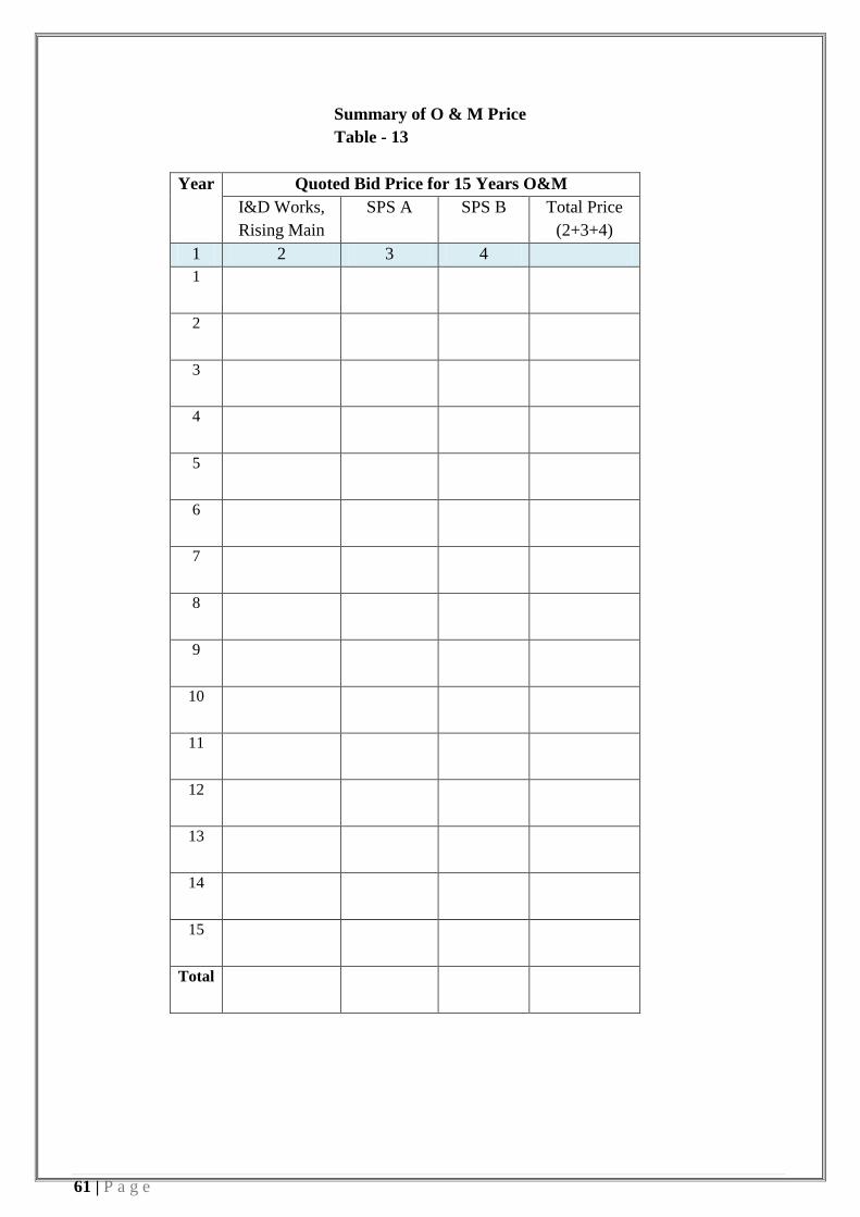
61 | P a g e
Summary of O & M Price
Table - 13
Year
Quoted Bid Price for 15 Years O&M
I&D Works,
Rising Main
SPS A SPS B Total Price
(2+3+4)
1 2 3 4
1
2
3
4
5
6
7
8
9
10
11
12
13
14
15
Total
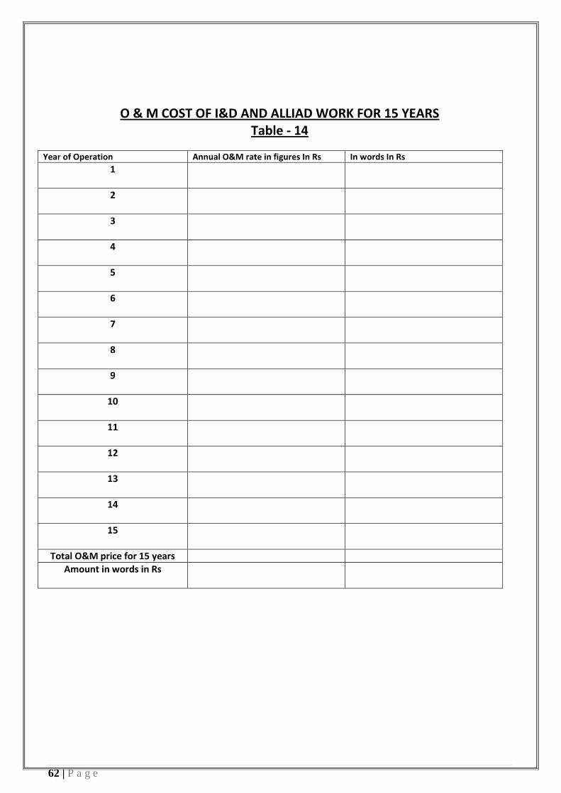
62 | P a g e
O & M COST OF I&D AND ALLIAD WORK FOR 15 YEARS Table - 14
Year of Operation Annual O&M rate in figures In Rs In words In Rs
1
2
3
4
5
6
7
8
9
10
11
12
13
14
15
Total O&M price for 15 years
Amount in words in Rs


TABLE- 9 Price for Operation & Maintenance of SPSA for 15 years , Table – 15
Sl.
No.
Description Lump Sum Price
1ST
Yea
r
2nd
Yea
r
3rd
Ye
ar
4th
Year
5th
Year
6th
Year
7th
Yea
r
8th
Yea
r
9th
Yea
r
10th
Yea
r
11th
Yea
r
12th
Yea
r
13th
Yea
r
14th
Yea
r
15th
Yea
r
Fixed Price
1 O & M cost including Spare
Parts, tools and tackles
Manpower, repair &
maintenance of civil works,
electromechanical works and
all other costs related to
operation and maintenance
of SPS facility but excluding
energy consumption.
Variable Price
2 Cost of electrical Energy
consumption per MLD of
sewage pumped (Guaranteed
Energy Consumption per
MLD x Base Rate of
Electricity Tariff.)
3 Indicative Sewage Flow to
be pumped per year – MLD
3.11 3.19 3.
27
3.36 3.44 3.52 3.60 3.69 3.77 3.85 3.93 4.01 4.10 4.18 4.26
4 Cost of Energy* (2x3)
Total Price for O&M of
SPS-A for 15 years ( 1+4)
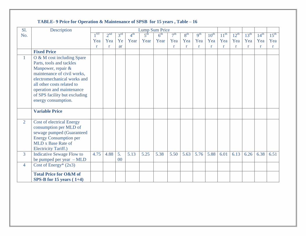
TABLE- 9 Price for Operation & Maintenance of SPSB for 15 years , Table – 16
Sl.
No.
Description Lump Sum Price
1ST
Yea
r
2nd
Yea
r
3rd
Ye
ar
4th
Year
5th
Year
6th
Year
7th
Yea
r
8th
Yea
r
9th
Yea
r
10th
Yea
r
11th
Yea
r
12th
Yea
r
13th
Yea
r
14th
Yea
r
15th
Yea
r
Fixed Price
1 O & M cost including Spare
Parts, tools and tackles
Manpower, repair &
maintenance of civil works,
electromechanical works and
all other costs related to
operation and maintenance
of SPS facility but excluding
energy consumption.
Variable Price
2 Cost of electrical Energy
consumption per MLD of
sewage pumped (Guaranteed
Energy Consumption per
MLD x Base Rate of
Electricity Tariff.)
3 Indicative Sewage Flow to
be pumped per year – MLD
4.75 4.88 5.
00
5.13 5.25 5.38 5.50 5.63 5.76 5.88 6.01 6.13 6.26 6.38 6.51
4 Cost of Energy* (2x3)
Total Price for O&M of
SPS-B for 15 years ( 1+4)

Sr.no. Item Description
Unit Qty Rate Amount
1 SCADA System Ls 1
Total Cost, Rs

Annexure – 9
Conditions of Particular reference/Special Conditions
1. Government land is available for STP and pumping station. Environmental clearances, the specific requirements and the status in this regard shall be made available by the . BUIDCo will facilitate in getting such clearances/ approval.
2. Survey of specified drain, investigation preparation of drawing design shall be done by in specified time and no additional payment shall be made on this account.
3. shall submit drawing design of each proposed component approval to be gotten from competent authority of BUIDCo.
4. shall get the approved working drawing & design from the Engineer in charge before commencement.
5. Drains to be intercepted and diverted to proposed STP in ward no-15 near makhtakiya area, to prevent the pollution load of river Ganga..
6. The objective star gets of this project is communication and publication awareness creation activities aimed at facilitating project implementation and to create awareness on need, benefits and approach for Ganga rejuvenation.
7. It will be mandatory for to operate and maintain the build infrastructure for 15 years post commissioning.
8. The specified and mentioned specifications of quality of material and work to be ensured by . 9. Quality test of materials should be submitted by on his own expenditure. 10. Process Instrumentation, Control. and SCADA System. The instrumentation shall include online
measurement of influent and effluent parameters for sewage, sludge and sludge gas. Process Instrumentation, Control. and SCADA System shall include continuous monitoring the process parameters, process flow, tank level and other equipment protection devices. These measurements shall be connected to a network of Programmable Logic Control (PLC) based unit process controllers that shall generate pre-programmed monitoring and control actions for process, equipment and other control devices. A Supervisory Control and Data Acquisition (SCADA) system, networked to the PLC unit process controllers shall acquire and display process parameters, process flow, tank level, etc., monitor and issue remote control actions for maintaining process control. The SCADA system shall also achieve pre-determined process parameters and originate custom performance reports for management reporting.
1.1. Operate the STP, I&D works with Pumping Stations, for a period of 15 years as specified below:
1.1.1. General Scope
a. The Contractor shall operate and maintain the STP under the Contract complete including the road works, landscaping, civil/structural, mechanical components,

instrumentation system, Electrical System, all utility and ancillary buildings for the period of fifteen (15) years from the date of successful completion of "Tests after Completion of the Works".
b. The Contractor shall make his own arrangements at his own cost for Works operation personnel, lubricants, diesel, spares, tools and tackles, routine maintenance, screenings collection, desilted material collection, transportation and disposal, co-ordination with respective pollution control board, agency supplying power to the STP, and any other activity required for the operation and maintenance of the constructed Works in full compliance with all applicable rules, regulations, laws, codes, effluent quality requirements and any other limitations.
c. Carrying out continuous flow measurements and recording of treated & untreated sewage at outlet and inlet of STP, regular calibration, cleaning, maintenance and replacement when required of measuring devices;
d. Collecting samples of influent and effluent and analyzing & testing them on a daily basis (inhouse) and getting tests done at weekly basis from laboratory of Bihar PCB to determine the quality of sewage and performance of the treatment plant. Minimum 3 grab samples representative of different flow conditions (quantum and quality wise) in the day of the treated effluent shall be drawn every week jointly by the Owner and the Contractor and the results of the test report shall be binding on both the parties.;
e. Take all necessary measures to minimize the power consumption in carrying out its operations.
f. operate electrical equipment during power failures by making appropriate alternative arrangements,
g. Store or dispose: (i) the Residual Matter obtained after the processing and treatment of the Sewage such as sludge, grit, waste screens etc.; and (ii) the Residual Treated Water obtained from treatment of Sewage in a manner which is compliant to all applicable environmental laws and rules;
h. The Contractor shall submit a weekly report to the Owner detailing the Operation and Maintenance indicating the labour hours expended, Electrical Power Consumed and other Consumables consumed and also problems faced and rectified.
i. The Contractor shall submit detailed schedule/manual of all O& M activities with references of equipment manufacturers’ maintenance schedules/manuals to the Owner for review and approval.
j. The Contractor shall submit Guidelines and Instructions manual for the maintenance staff of all levels for all the tools, plants and equipment and Operating

STP to maintain the service levels within the standards prescribed within the contract;
k. The Contractor shall carry out all O&M activities as per the approved Operation and Maintenance Manuals.
l. During the Operation and Maintenance period, the Contractor shall ensure that the sewage detention time in wet well not exceeds 30 min. and there is no backflow of sewage.
m. The Contractor’s responsibility shall also include the safety and security of the Works during the course of Operation and Maintenance.
n. Acquire and maintain sufficient stock of consumables such as chemicals, algal nutrients, safety gear, grit screens etc. and procure necessary electrical and mechanical equipment required for operations and maintenance of STP to ensure continuous operations.
o. Establish a Project office to manage the Project. The Project office can be located at the sewage treatment plant campus or at any other appropriate location where land is made available by the Owner.
p. All Project sites shall be well secured and kept in a clean and hygienic condition with sufficient measures for safety and security of man-power, built structures, equipment and other system components.
q. During Operation and Maintenance period, the Contractor shall appoint an Contractor and Electrical/Mechanical Technician. In addition, the Contractor shall appoint suitable number of Contractors, drivers, cleaners,fitters, electricians, helpers, gardeners, office peons, security guards, labourers as required for the operation and maintenance of complete proposed STP for three shifts and adequate other staff / supporting personnel during general Shift. Security of man-power, built structures, equipment and other system components
1.1.2. General Scope
a. To Operate and maintain the sewage treatment plant, all instruments and mechanical, electrical equipment in accordance with the aim and purpose of treatment. The plant &equipment covered under the above contract will be totally attended to, by the Contractor including any “Troubleshooting” to ensure smooth and trouble free operation.
b. The Contractor will monitor the performance of the sewage treatment plant; conduct the analysis of the inlet sewage and water quality after treatment. Contractor shall initiate and take adequate actions to ensure smooth and satisfactory performance / running of the plants on a 24 hours / round the clock basis.

c. The Contractor shall prepare and implement an effective plant maintenance programme in consultation with the Owner. It is an absolutely Contractor’s responsibility to look after all sorts of maintenance whether preventive, Minor, Major, or break-down
d. The Contractor will determine operating parameters, select settling (Chemical doses etc.) and generally optimize the process, and working of the treatment plant. Excessive chemical dozing i.e. dose more than normal should be avoided otherwise penalty shall be levied and recovered from the Contractor.
e. The Contractor should plan & procure all spares, Polyelectrolyte and all consumables including chemicals, grease, lubricating oil, cleaning agents, laboratory reagents etc. Further the Contractor will plan about the requirement well in advance (At least 4 months) and procure the material from the market.
f. The Contractor will be responsible for keeping up-to-date record of documents including History Card for equipment and maintaining every day log book relating to various analyses performed.
g. The Contractor shall maintain and update logbook, in which details of operational parameters are recorded in every shift and at regular interval say hourly or as decided mutually.
h. The Contractor will prepare and submit a daily report of plant performance and will assist the Owner in preparing the necessary documents for their purpose and records.
i. The Contractor will be responsible to carry out day to day periodic maintenance, necessary to ensure to smooth and efficient performance / running of all equipment / instruments comprising the sewage treatment plant and maintaining the record of the same.
j. The Contractor shall have to issue identity cards with photographs to all the staff employed for Operation and Maintenance. The list of the same shall be submitted to the Owner mentioning qualification & experience.
k. The Contractor will also be responsible to carry out day to day Maintenance of the rising main inside the STP premises.
l. The Contractor will employ minimum staff for operation and maintenance of the Plant as per the list mentioned in the bid document.
m. The staff of Contractor will always remain in contact with the Junior Engineer, Assistance Engineer/Electrical Supervisor, in charge of the Plant deployed by the Owner and follow their instruction.

n. Unsatisfactory and inefficient running of the plant and unnecessary and excessive usage of spare, consumable, etc. supported by the reasons which are under control of Contractor will be highly objected. In such cases Design Build Operations Engineer . ’s decision will be final and binding to the Contractor.
o. It is required that at least once in every one month a technical expert other than the Monthly Staff of the Contractor will visit the plant and will suggest if required, to improve the efficiency and working of the plant etc. No separate payment will be made for such visits. The visit must be recorded and outcome of the visit/minutes of the meeting should be got signed by Owner authorities without which the visit shall not be considered.
p. Contractor will comply with all safety rules and regulations as followed by the Owner.
q. The Owner will not be responsible for any accident /injury to the staff of the Contractor. Further the Owner will not provide any insurance or medical facility to the staff of Contractor. The responsibility lies with the Contractor.
r. All Central/State Government / Semi-Government / Local Body’s Rules and Regulations pertaining to this contract shall be followed and observed by the Contractor without any extra cost to the Owner.
s. No accommodation / guesthouse / transportation facility will be provided by the to the Contractor. Operation & maintenance staff will not be allowed any accommodation facility inside the plant premises.
t. The duration of the O&M shall be 180 months from the date of successful commissioning of the STP. The same can be extended for the further period if the Owner so desires. The Contractor should employ all the staff within two days of successful commissioning. The Contractor will provide the necessary tools and tackles required for day-to-day maintenance.
u. The scope of work also includes cleaning of complete plant area including floor, toilet block railing, door, windows, light fixtures and ceiling etc. The entire premises of the plant area shall also be cleaned and maintain by the Contractor regularly.
v. This work is inclusive of but not limited to operation, maintenance, housekeeping, cleaning, removing sludge by its own carrier arrangement & disposes it off as per Owner’s instructions. Preparing data recording, correspondence work to Owner and Government Departments, etc. All this work should be done as per standard practices and by following labour, factory, electrical, STATE PCB, and all other latest updated regulations, Indian standards etc. as applied of Local, State and Central Government of India.
w. The Contractor will not employ persons who are, pronounced guilty or charged with indiscipline.

x. Right is reserved by Owner of suspension, dismiss ion, termination of any officer / staff employed by Contractor. He shall have taken prior permission to employ or to terminate his personals.
y. No watch and ward, safety insurance, security, storage, housing accommodation etc. will be provided by Owner. This will be responsibility of Contractor.
z. Consumable items like rubber bush, graphite packing, rubber sheet, nut-bolts, material required for cleaning and housekeeping etc. are to be brought by the Contractor.
aa. Monitoring should be done as per guideline given by Design Build Operations Engineer . . Contractor has to maintain all the parameter of effluent within stipulated limit or he will be penalized for not maintaining the parameters given by STATE PCB and Owner. All expenditure incurred for the same like, suite fee, court fee, case fee, or the penalty as decided by Engineer of Owner and penalty charged by STATE PCB will be charged to Contractor and deducted from his bills, S.D etc.
bb. Contractor shall have to test the effluent / influent at his own cost at the plant lab on daily basis. The same be verified by and checked by Owner whenever required. The Contractor shall also have to test the effluent / influent at STATE PCB lab for different parameter on weekly basis at his own cost.
cc. No equipment shall remain ideal or un-attended or damaged for the period of 3 days.
dd. The payment of O & M charges will be made as per the tender conditions. The other terms and condition described in these complete tender documents, wherever applicable shall remain unchanged. In case of any discrepancy the decision of Design Build Operations Engineer . will remain final & binding on the Contractor.
ee. During Operation & Maintenance period, Contractor has to supply all the spares, at his cost during preventive, major-minor breakdown, replacement and maintenance work. No extra payment will be made for such maintenance on any ground. The payment for the same will be made strictly as per tender document irrespective of the number of break down / minor, major repairs replacements. During the O & M Contractor will have to enter annual maintenance agreement with Manufacturers of all major Mechanical Equipments like Centrifuge, Air Blowers, Screens, Decanters etc.
ff. Contractor will have to maintain required Power Factor as per STATE EB rules and regulations. Incase penalty is levied by STATE EB for not maintaining the Power Factor the same will be recovered from the. Contractor

gg. Maintenance of Garden, Lawns, Plants, Bushes, Plantation of new Plants, Lawns etc. and feeding, gardening, cleaning etc. is in the scope of the Contractor. No separate payment will be made for the same.
hh. The Contractor during his O&M period will have to follow all the guidelines set by STATE PCB for Operation & Maintenance of STP.
ii. Operation and maintenance of all General facilities and utility services including all other components of work done under this contract.
jj. Operation and maintenance of PLC based automation system and all instruments installed in the STP including all repairs, replacements towards the entire instrumentation works during the O & M period shall be in the scope of Contractor.
kk. Any other services required for smooth running of the scheme.
ll. The Contractor shall also dispose off the sludge, screenings, grit and any other material, as per specifications and to the satisfaction of the Design Build Operations Engineer . . It is to be noted that all costs during the O&M period, excluding the cost of power and chlorine are to be borne by the Contractor. The Contractor is to ensure that the following guarantees are maintained during the operation & maintenance period:
i. for quality of effluent
ii. for consumption of chemicals
iii. for automation
mm. The Contractor shall provide on job training to the Local body staff as per specifications.
nn. At the end of every 2(1/2) year of operation & maintenance period, an assessment of the condition of the plant has to be done by the Owner through third party inspection at Owner’s cost and based on that assessment the Contractor shall, at no extra cost to the Owner, repair and re-condition all the mechanical equipment in the concluding year of the O&M contract to a condition so that they are in running condition with regular preventive and recommended maintenance as per manufacturer's recommendations or as per CPHEEO manual.
oo. Variability of through output: If the quantity of treated sewage from the Facility can be increased in the existing system without impacting the annual fixed costs to the Contractor, the Contractor shall comply with such requirements. For a sustained requirement of higher throughout from the Facility, the Contractor may be required to frame and submit a proposal that shall be implemented if mutually acceptable.

1.1.3. Treated Sludge Disposal
The Contractor shall operate the Sewage Treatment Plant such that the sludge produced is of a spreadable consistency and the volume of sludge produced after necessary process is minimum. The sludge generated from the STP shall be disposed of through proper approved means of transport to the Compost yard site as designated by the Owner
1.1.4. Chemical Requirements
All chemicals consumed to operate the Sewage Treatment Plant and other facilities under this contract will be borne by the Contractor.

Annexure - 10
Table 33: Effluent Disposal Standards
S.No Industry Parameters Standards 1 2 3 4
Effluent discharge standards (applicable to all mode of disposal) "105 Sewage
Treatment Plants (STPs)
Location Concentration not to exceed
(a) (b) pH Anywhere in the country 6.5-9.0 Bio-Chemical Oxygen Demand (BOD)
Metro Cities*, all State Capitals except in the State of Arunachal Pradesh, Assam, Manipur, Meghalaya Mizoram, Nagaland, Tripura Sikkim, Himachal Pradesh, Uttarakhand, Jammu and Kashmir and Union territory of Andaman and Nicobar Islands, Dadar and Nagar Haveli Daman and Diu and Lakshadweep
20
Areas/regions other than mentioned above 30 Total Suspended Solids (TSS)
Metro Cities*, all State Capitals except in the State of Arunachal Pradesh, Assam, Manipur, Meghalaya Mizoram, Nagaland, Tripura Sikkim, Himachal Pradesh, Uttarakhand, Jammu and Kashmir and Union territory of Andaman and Nicobar Islands, Dadar and Nagar Haveli Daman and Diu and Lakshadweep
<50
Area/regions other than mentioned above <100 Fecal Coliform (FC) (Most probable Number per 100 mililiter, MPN/100ml
Anywhere in the country <1000
* Metro Cities are Mumbai, Delhi, Kolkata, Chennai, Bengaluru, Hyderabad, Ahmedabad and Pune.
Note:
i. All values in mg/I except for pH and Fecal coliform. ii. These standards shall be applicable for discharge into water bodies as well as for land
disposal/applications. iii. The standards for Fecal Coliform shall not apply in respect of use of treated effluent for
industrial purposes. iv. These Standards shall apply to all STPs to be commissioned on or after the 1 June, 2019 and
the old existing STPs shall achieve these standards within a period of five years from date or publication of this notification in the Official Gazette.

v. In case of discharge of treated effluent into sea, it shall be through proper marine outfall and the existing shore discharge shall be converted to marine outfalls, and in cases where the marine outfall provides a minimum initial dilution of 150 times at the point of discharge and a minimum dilution of 1500 times at a point 100 meters away from discharge point, then, the existing norms shall apply as specified in the general discharge standards.
vi. Reuse/Recycling of treated effluent shall be encouraged and in case where part of the treated effluent is reused and recycled involving possibility of human contact, standards as specified above shall apply.
vii. Central Pollution Control Board/State Pollution Control Boards/Pollution Control Committees may issue more stringent norms taking account to local condition under section 5 of the Environment (Protection) Act, 1986.".