annex 4 part 1-fdh (i) installation guide
TRANSCRIPT

1
FDH (I) INSTALLATION GUIDE
1. Introduction This guide will serve as reference in installing various types of FDH, including the rack module placements, patching & routing of cables, labeling, record updating and testing procedures.
Terminologies:
Rack Frame – 42U Open Rack FDH (R&M)
Feeder Module – 24 ports unirack module where incoming cable or feeder cables are terminated
Splitter Module – 2 X 32 Splitter module (residential or business splitter)
Drop Module – 24 ports unirack module (DME Prolink, R&M) where drop cables are terminated. Also, Drop modules are identified as ODF1, ODF2, ODF3, and so on.
2. Test Equipments and Tools OTDR Optical Power Meter / Optical Light Source Visual Fault Locator Fast-field Connector Toolkit Drill Machine Drill Bit with hole saw attachment (38mm & 25mm) Cable Cutter Side Cutter Basic Tools (Pliers, Screw Drivers, Measuring Tape etc.)
3. 42U FDH Open Rack Frame Open rack is mainly used for terminating fiber in the POP location but it was used as indoor FDH for large residential buildings.
3.1 Configuration 1: FDH Setup for maximum 256 tenancies
The following configuration shall be used in buildings where tenancies are ranging from 100 to 224 and can be expanded up to maximum 256 tenancies.
42U open rack frame 1X1U Feeder module 1X1U PC Drawer 8X1U Splitter modules 11X1U Drop module patch panel
Additional materials
10mm Spiral Plastic Wrap 8mm Spiral Plastic Wrap 6mm Spiral Plastic Wrap ( for Patch cord) Cable tie (Length: 203mm Width: 3.6mm) Velcro Straps Trunking PVC size 50X100mm, 2.9meters color white
Frame and Feeder Module
Install the rack frame as per instruction guide. Secure the frame and keep it sturdy. Then install the Feeder module at the bottom of the frame.

2
FO Feeder Cable
Route the FO feeder cable in to the FDH trunking. Fusion splice the required number of fibers with the pigtails. Coil the spare fibers properly in the splice tray. Clean connector and connect the pigtails to the Feeder module’s adaptor.
Splitter Modules
Install the Splitter module starting from the bottom, after the Feeder module. Note: Keep 1U space for every module installed.
FO Drop Modules Mark the PVC trunking and drill 38mm hole. The hole shall be in line with
Drop module’s side access cable entry. Remove the sharp edges using sand paper.
Prepare the Drop module (shown is DME Prolink type). Slide-open the Drop module and remove the splice cassette.

3
Remove the Splice cassette’s screw stud. Then install SC/APC adapter.
Install PC drawer first for Splicing Record storage after Splitter 8 with 1U gap in between.
After the PC drawer, install the first Drop module with no gap in between. Note: Complete the FO drop cable arrangement in the first Drop module before installing the next Drop module for better access.

4
FO Drop Cable Installation & Termination
Install the Drop cable and bunch it into 24 (preferably cables that emanates floor-wise and flat-wise).
Route the Drop cables in the trunking to determine the appropriate cable loops.
Arrange the Drop cable loops in such a way it reaches the bottom of the trunking.
Then insert the Drop cables in the trunking’s access hole and into the Drop module’s opening (left side cable entry).

5
With proper Drop cable loops in the trunking, mark the Drop cables in reference to Drop module entry point.
Pull the Drop cable and measure 1meter from the cable mark. The 1 meter length of cable will serve as Drop cable loop inside the Drop module.
Cut the excess cable lengths. Keep the fiber scrap and dispose it properly.
Prepare the Drop cable and install FAST-field connector. Note: Use a black mat to catch the fiber scrap during fiber cutting and cleaving and dispose it properly.

6
Test the Drop cable for any faults (Refer to Appendix 3/Continuity test). Replace faulty Drop cables if any. Arrange the first set of Drop cables in circular loop and clean the connectors.
Note: Drop cable should be continuous length and should not be spliced with other cable segment to extend cable reach.
Then connect the Drop cables to the SC/APC adaptors according to flat numbers (preferably in ascending order).
Note: Drop module top cover can be removed for better access.
Secure the Drop cables using 45cm long spiral plastic wrap (8mm size). Start the wrapping approximately 25cm from the connector.
Re-arrange the Drop cable in circular loop.

7
Adjust the cables and provide approximately 12cm diameter of cable loop when Drop module is fully open. Then secure the cables using cable tie.
After completing the first set, arrange the second set of cables. Clean the connectors and connect to SC/APC adaptors. Arrange the cable and install 45cm long spiral plastic wrap (8mm size).
Install cable tie in the upper most holes of the Drop module to secure the cables.
Install a 20cm long spiral plastic wrap (10mm size) to the bunch of 24 Drop cables and secure the cables using cable tie.
Then fix the Drop module cover.

8
After completing the cable connections, re-arrange the Drop cable in the trunking. Then close the cover. Note: Bunch the cables emanating from the Drop module either using electrical tape or cable tie for easy cable identification.
After completing the Drop cable connections, prepare the labeling machine. Label the FO drop cable in the Drop module. Refer to Appendix 1 for the
labeling guide.
Print the label and stick the label properly in the cable.

9
After completing all FO drop cable labeling, print the label for Splitter and Drop modules. Place the label on the left side part of the modules.
Place the Splitter label on top of its cover. And for the Drop module and PC drawer, place the label at the front side of the
patch cord management.
FO Patch Cord Trunking
Install 189.5cm long PVC trunking (size 50X100mm) on the left side of the frame.
Secure the trunking using an L-Type clamp.

10
Mark the trunking where access holes are to be provided. Note: Holes should be in-line with the Splitter and Drop modules.
Drill 25mm holes and remove the sharp edges using sand paper.
FO Patching (Splitter to Drop Module)
a) Using Fostec SC/APC 0.9mm Patch Cord
Install 2-meter patch cords. Connect one end to Splitter’s output port, and the other end to the Drop module input port based on the flats and splitter port’s assignment (Refer to Appendix 2).
After completing the patching in one splitter, arrange the patch cord into bunch of 16 and secure the patch cords using a 30cm long spiral plastic wrap (size 6mm).

11
At the Drop module side, arrange the first set of patch cords into bunch of 12 and secure it using a 65cm long spiral plastic wrap (size 6mm).
Form a loop as shown.
Then arrange the second set of patch cords as shown and install a 65cm long spiral plastic wrap (size 6mm).
Secure the patch cords using Velcro straps. Note: When opening and closing the Drop module, guide the patch cords to slide smoothly in the trunking.
b) Using Corning SC/APC 2mm Patch Cord
Install two-meter patch cords. Connect one end to the Splitter’s output port and the other end to the Drop module input port.
Arrange the patch cords and secure it using Velcro strap. Then install a 30cm long spiral plastic wrap (size 10mm).
In the Drop module end, arrange the patch cords and secure it using Velcro strap
Then Install a 45cm long spiral plastic wrap (size 10mm).

12
FO Patching (From Feeder module to Splitter)
Install a 2-meter patch cord. Connect one end from the Feeder module and the other end to Splitter Input 1.
Arrange the patch cords in the Feeder module and secure it using a 45cm long spiral plastic wrap (size10mm). Note: Guide the patch cords in the trunking when opening and closing the Feeder module.
After completing the patching, label all patch cords. Refer to Appendix 1 for labeling guide.
Print FDH label (OLT/FDH Number & EID) in a sticker and place it on top of the 4U plate of the frame.
Test the FDH and measure the Power levels. (Refer to Appendix3/Post-Installation Testing)
Update the Fiber Splicing Record (Appendix2) and place it in PC drawer. Keep the work area/ telephone room tidy and clean at all times.
13
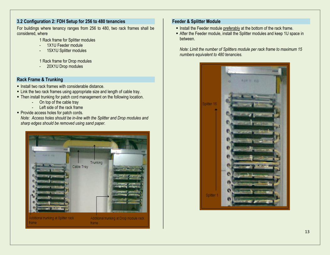
3.2 Configuration 2: FDH Setup for 256 to 480 tenancies
For buildings where tenancy ranges from 256 to 480, two rack frames shall be considered, where
1 Rack frame for Splitter modules - 1X1U Feeder module - 15X1U Splitter modules
1 Rack frame for Drop modules - 20X1U Drop modules
Rack Frame & Trunking
Install two rack frames with considerable distance. Link the two rack frames using appropriate size and length of cable tray. Then install trunking for patch cord management on the following location.
- On top of the cable tray - Left side of the rack frame
Provide access holes for patch cords. Note: Access holes should be in-line with the Splitter and Drop modules and sharp edges should be removed using sand paper.
Feeder & Splitter Module
Install the Feeder module preferably at the bottom of the rack frame. After the Feeder module, install the Splitter modules and keep 1U space in
between. Note: Limit the number of Splitters module per rack frame to maximum 15 numbers equivalent to 480 tenancies.

14
Drop Module Install the Drop modules on the other Rack frame starting at the bottom. Keep 1U space in between.
Note: Limit the number of Drop modules per rack frame to maximum 20 numbers.
FO Drop Cable Installation and Termination
All drop cables should connect from the back of the Drop module with specific spare length according to the desired Flat/Floor labeling.
Install connector Test the cables before connecting to the Drop module. Refer to Appendix
3/Drop cable continuity testing. Replace cables if faulty.
Note: Drop cable should be continuous length and should not be spliced with other cable segment to extend cable reach.
Arrange the cable in circular loop inside the Drop module, clean connector and connect to SC/APC adaptor.

15
Then secure the cables with Velcro strap. Note: Provide enough cable loops to avoid sharp cable bends when opening the Drop module.
FO Patching (Feeder Module to Splitter Module) Connect the patch cord from the Feeder module to Splitter module input port
number 1. Route the patch cords in the trunking located at the left side of the rack frame.
FO Patching (Splitter Module to Drop Module) Connect the patch cord from the Splitter port to Drop module ports according
to assigned port location.
At the Splitter module, route the patch cords on the left side of the rack frame trunking.

16
At the Drop module rack frame, patch cord termination from the Splitter module to Drop module should be made balance, where
- Ports 1-12, patch cord should be routed on the left side of the module.
- Ports 13-24, patch cord should be routed on the right side of the module.
Note: When opening and closing the Drop module, guide the patch cords to slide smoothly in the trunking.
Secure the patch cords using spiral plastic wrap and Velcro straps.
Provide all the necessary labels. Refer to Appendix 1. Test the FDH and measure the Power levels. (Refer to Appendix3/Post-
Installation Testing). Update the Fiber Splicing Record (Appendix2) and place it in PC drawer.

17
4.0 GPX-147 FAT3202 Wall-mount type FDH
This type of indoor FDH shall be used for buildings where tenancy is ranging from 50 to 100 home passes. FDH configurations are as follows; 128 maximum ports capacity Requires modular type of splitters Splitter mounting can hold 2 splitters each Additional Materials Cable Tray (30 X 290cm)
Cabinet Preparation Install SC/APC adaptors for input and Drop cables. Install the additional Splitter in the slot where the first splitter is located. Clean connectors and connect to the SC/APC adaptors.
Note: Install Splitter output tails based on port numbers in the cabinet.
Cabinet Installation Mark the wall to drill using Line Drawing Template board for Cabinet installation.
Then drill the wall and install anchor bolts.
Install the cabinet and tighten the anchor bolts.
18
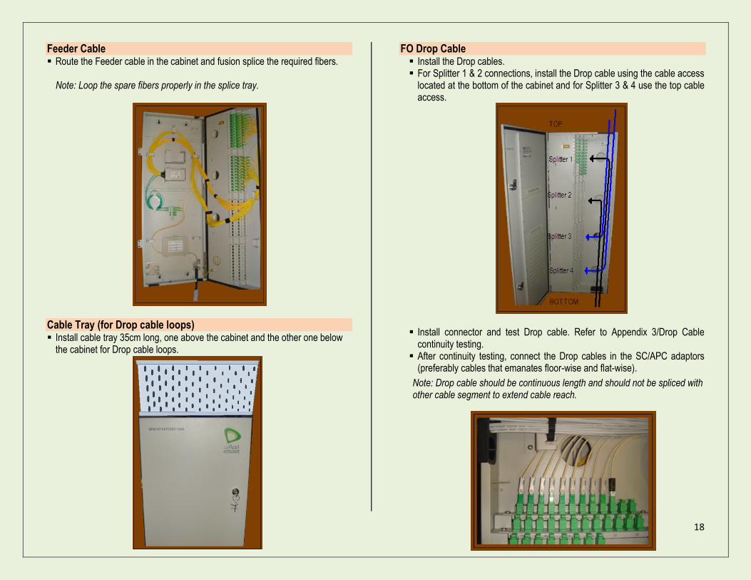
Feeder Cable Route the Feeder cable in the cabinet and fusion splice the required fibers.
Note: Loop the spare fibers properly in the splice tray.
Cable Tray (for Drop cable loops) Install cable tray 35cm long, one above the cabinet and the other one below
the cabinet for Drop cable loops.
FO Drop Cable Install the Drop cables. For Splitter 1 & 2 connections, install the Drop cable using the cable access
located at the bottom of the cabinet and for Splitter 3 & 4 use the top cable access.
Install connector and test Drop cable. Refer to Appendix 3/Drop Cable continuity testing.
After continuity testing, connect the Drop cables in the SC/APC adaptors (preferably cables that emanates floor-wise and flat-wise).
Note: Drop cable should be continuous length and should not be spliced with other cable segment to extend cable reach.
19
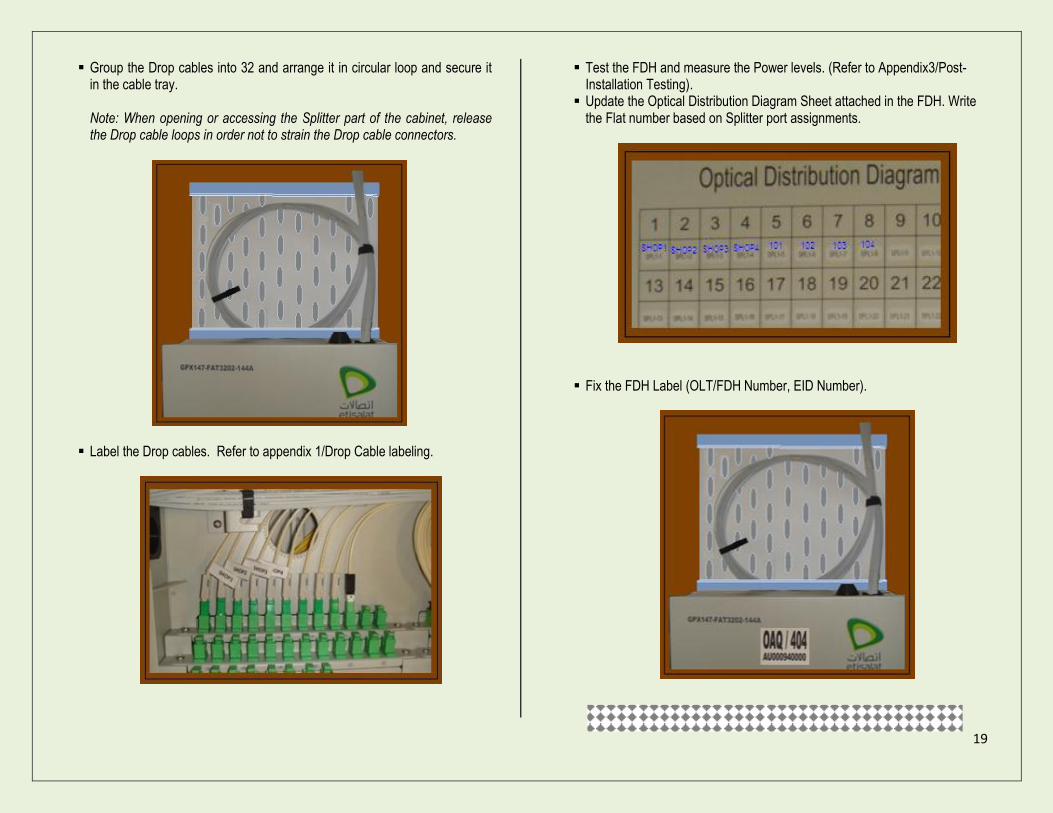
Group the Drop cables into 32 and arrange it in circular loop and secure it in the cable tray. Note: When opening or accessing the Splitter part of the cabinet, release the Drop cable loops in order not to strain the Drop cable connectors.
Label the Drop cables. Refer to appendix 1/Drop Cable labeling.
Test the FDH and measure the Power levels. (Refer to Appendix3/Post-Installation Testing).
Update the Optical Distribution Diagram Sheet attached in the FDH. Write the Flat number based on Splitter port assignments.
Fix the FDH Label (OLT/FDH Number, EID Number).
20
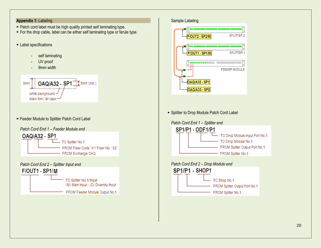
Appendix 1: Labeling
Patch cord label must be high quality printed self laminating type. For the drop cable, label can be either self laminating type or ferule type.
Label specifications
- self laminating
- UV proof
- 9mm width
Feeder Module to Splitter Patch Cord Label Patch Cord End 1 – Feeder Module end
Patch Cord End 2 – Splitter Input end
Sample Labeling
Splitter to Drop Module Patch Cord Label Patch Cord End 1 – Splitter end
Patch Cord End 2 – Drop Module end

21
Sample Labeling
FO Drop Cable Label – Drop Module end
Splitter and Drop Module Label
FDH Label
Appendix 2: Fiber Splicing Record Print the Fiber Splicing Record, bind it in a plastic folder and keep in PC
drawer. Inform concerned Department for any changes in patching.
SPLITTER 1 Connection Details
Splitter Port No. Drop Module ODF
Port No.
Flat No. Notes No. Port
1 1 1 1 SHOP1 Modern Bakery
2 1 2 2 SHOP2 German Rent-a-car
3 1 3 3 SHOP3 The Textile Co.
4 1 4 4 SHOP4 Clock Grocery
5 1 5 5 MZ01 6 1 6 6 MZ02 7 1 7 7 MZ03 8 1 8 8 MZ04
9 1 9 9 101
10 1 10 10 102
11 1 11 11 103
12 1 12 12 104
13 1 13 13 201
14 1 14 14 202
15 1 15 15 203
16 1 16 16 204
17 1 17 17 301
18 1 18 18 302
19 1 19 19 303
20 1 20 20 304
21 1 21 21 401
22 1 22 22 402
23 1 23 23 403
24 1 24 24 404
25 2 1 25 501
26 2 2 26 502
27 2 3 27 503
28 2 4 28 504
29 2 5 29 601
30 2 6 30 602
31 2 7 31 603
32 2 8 32 604
E3 SECTOR/BLOCK
NO.
PLOT/BLDG.
NO.
C29
OAQ/544 OLT / FDH NO.
Master EID
NO.
AU000998000

22
Appendix 3: Installation Test Procedures Drop Cable Continuity Testing
1. Connectorize one end of Drop cable. 2. Clean the connector and connect the Visual Fault Locator. 3. Check the cable continuity and replace Drop cable if faulty.
Note: Perform the cable continuity test first before connecting the Drop cable in the FDH. Post-Installation Testing (Insertion Loss Measurement)
Measurement Setting: 1310,& 1550nm
Test Result Format
Sector/Block Number: E3 Plot Number: C29
OLT/FDH Number: OAQ/5505 Master EID: AU000998000
SPLITTER 1
Wavelength Flat No. Wavelength
Remarks 1310 1550 1310 1550
Output
1 SHOP1
2 SHOP2
3 SHOP3
4 SHOP4
5 MZ01
6 MZ02
7 MZ03
8 MZ04
9 101
- -
- -
29 601
30 602
31 603
32 604
1. Connect Optical Light Source to Splitter input port. 2. Set the reference power level to 0dBm. 3. Connect Optical Power Meter or OTDR to Splitter output port 1 and measure
received power level. 4. Measure the remaining Splitter output ports and write the test results. 5. After measuring the Splitter output ports, connect Optical Power Meter or OTDR
in the Drop cable (at rosette end). 6. Measure the received power level and write the test results for each Flat. 7. After completing the test measurements in each Flat, compare the measured
levels based on the Power Level calculation below. Power Level = Splitter Output measured level – Losses Where Losses are as follows; Patch Cord = 1 X 0.6dB SC/APC Adaptor Insertion Loss = 2 X 0.2dB Fast-field Connector = 2 X 0.4dB Drop Cable = 0.35dB/km Example: Flat604 with 40 meters Drop cable, and Splitter1 Port32 measured output level is -19dBm. Power Level = -19dBm – (0.6+0.4+0.8+0.014)dB = -19dBm – 1.814dB Power Level= -20.814dBm
8. If the difference between measured levels and calculated levels is more than 1 dB, then check patch cords, Drop cable and connectors for any faults and rectify.
9. Follow steps 1 to 8 for the remaining Splitters.

23
Appendix 4: ODF Port Assignment
Drop Module ODF Port Number Assignment
Drop Module / ODF20 ODF 457 to 480
Drop Module / ODF19 ODF 433 to 456
Drop Module / ODF18 ODF 409 to 432
Drop Module / ODF17 ODF 385 to 408
Drop Module / ODF16 ODF 361 to 384
Drop Module / ODF15 ODF 337 to 360
Drop Module / ODF14 ODF 313 to 336
Drop Module / ODF13 ODF 289 to 312
Drop Module / ODF12 ODF 265 to 288
Drop Module / ODF11 ODF 241 to 264
Drop Module / ODF10 ODF 217 to 240
Drop Module / ODF9 ODF 193 to 216
Drop Module / ODF8 ODF 169 to 192
Drop Module / ODF7 ODF 145 to 168
Drop Module / ODF6 ODF 121 to 144
Drop Module / ODF5 ODF 97 to 120
Drop Module / ODF4 ODF 73 to 96
Drop Module / ODF3 ODF 49 to 72
Drop Module / ODF2 ODF 25 to 48
Drop Module / ODF1 ODF 1 to 24