annex 10 hit7080 itmn
TRANSCRIPT

SURPASS hiT 70804.0
Installation and Test Manual (ITMN)
A42022-L5977-A052-01-7630

2 A42022-L5977-A052-01-7630Issue: 1 Issue date: November 2007
Installation and Test Manual (ITMN)
The information in this document is subject to change without notice and describes only the product defined in the introduction of this documentation. This documentation is intended for the use of Nokia Siemens Networks customers only for the purposes of the agreement under which the document is submitted, and no part of it may be used, reproduced, modified or transmitted in any form or means without the prior written permission of Nokia Siemens Networks. The documentation has been prepared to be used by professional and properly trained personnel, and the customer assumes full responsibility when using it. Nokia Siemens Networks welcomes customer comments as part of the process of continuous development and improvement of the documentation.
The information or statements given in this documentation concerning the suitability, capacity, or performance of the mentioned hardware or software products are given "as is" and all liability arising in connection with such hardware or software products shall be defined conclusively and finally in a separate agreement between Nokia Siemens Networks and the customer. However, Nokia Siemens Networks has made all reasonable efforts to ensure that the instructions contained in the document are adequate and free of material errors and omissions. Nokia Siemens Networks will, if deemed necessary by Nokia Siemens Networks, explain issues which may not be covered by the document.
Nokia Siemens Networks will correct errors in this documentation as soon as possible. IN NO EVENT WILL NOKIA SIEMENS NETWORKS BE LIABLE FOR ERRORS IN THIS DOCUMEN-TATION OR FOR ANY DAMAGES, INCLUDING BUT NOT LIMITED TO SPECIAL, DIRECT, INDIRECT, INCIDENTAL OR CONSEQUENTIAL OR ANY LOSSES, SUCH AS BUT NOT LIMITED TO LOSS OF PROFIT, REVENUE, BUSINESS INTERRUPTION, BUSINESS OPPORTUNITY OR DATA,THAT MAY ARISE FROM THE USE OF THIS DOCUMENT OR THE INFORMATION IN IT.
This documentation and the product it describes are considered protected by copyrights and other intellectual property rights according to the applicable laws.
The wave logo is a trademark of Nokia Siemens Networks Oy. Nokia is a registered trademark of Nokia Corporation. Siemens is a registered trademark of Siemens AG.
Other product names mentioned in this document may be trademarks of their respective owners, and they are mentioned for identification purposes only.
Copyright © Nokia Siemens Networks 2007. All rights reserved.
f Important Notice on Product SafetyElevated voltages are inevitably present at specific points in this electrical equipment. Some of the parts may also have elevated operating temperatures.
Non-observance of these conditions and the safety instructions can result in personal injury or in property damage.
Therefore, only trained and qualified personnel may install and maintain the system.
The system complies with the standard EN 60950 / IEC 60950. All equipment connected has to comply with the applicable safety standards.
The same text in German:
Wichtiger Hinweis zur Produktsicherheit
In elektrischen Anlagen stehen zwangsläufig bestimmte Teile der Geräte unter Span-nung. Einige Teile können auch eine hohe Betriebstemperatur aufweisen.
Eine Nichtbeachtung dieser Situation und der Warnungshinweise kann zu Körperverlet-zungen und Sachschäden führen.
Deshalb wird vorausgesetzt, dass nur geschultes und qualifiziertes Personal die Anlagen installiert und wartet.
Das System entspricht den Anforderungen der EN 60950 / IEC 60950. Angeschlossene Geräte müssen die zutreffenden Sicherheitsbestimmungen erfüllen.
A42022-L5977-A052-01-7630Issue: 1 Issue date: November 2007
3
Installation and Test Manual (ITMN)
Statements of compliance
FCC statement
This device complies with part 15 of the FCC Rules. Operation is subject to the following two conditions: (1) this device may not cause harmful interference, and (2) this device must accept any interference received, including interference that may cause undesired operation. Shielded cables must be used with this unit to ensure compliance with the Class A FCC limits.
This equipment has been tested and found to comply with the limits for a Class A digital device, pursuant to Part 15 of the FCC Rules. These limits are designed to provide reasonable protection against harmful interference when the equipment is operated in a commercial environment. This equipment generates, uses, and can radiate radio frequency energy and, if not installed and used in accordance with the instruction manual, may cause harmful interference to radio communications. Operation of this equip-ment in a residential area is likely to cause harmful interference in which case the user will be required to correct the interference at his own expense.
CE statement
The CE conformity declaration for the product is fulfilled when the system is built and cabled in line with the information given in the manual and the documentation specified within it, such as installation instructions, cable lists or the like. Where necessary project-specific documentation should be taken into consideration. Deviations from the specifications or independent modifications to the layout, such as use of cable types with lower screening values for example, can lead to violation of the CE protection requirements. In such cases the conformity declaration is invalidated. The responsibility for any prob-lems which subsequently arise rests with the party responsible for deviating from the installation spec-ifications.
4 A42022-L5977-A052-01-7630Issue: 1 Issue date: November 2007
Installation and Test Manual (ITMN)
A42022-L5977-A052-01-7630Issue: 1 Issue date: November 2007
5
Installation and Test Manual (ITMN)
Table of ContentsThis document has 52 pages.
1 Preface . . . . . . . . . . . . . . . . . . . . . . . . . . . . . . . . . . . . . . . . . . . . . . . . . . . . . 91.1 Intended audience . . . . . . . . . . . . . . . . . . . . . . . . . . . . . . . . . . . . . . . . . . . . 91.2 Structure of this document . . . . . . . . . . . . . . . . . . . . . . . . . . . . . . . . . . . . . . 91.3 Symbols and conventions . . . . . . . . . . . . . . . . . . . . . . . . . . . . . . . . . . . . . . 101.3.1 Symbols used . . . . . . . . . . . . . . . . . . . . . . . . . . . . . . . . . . . . . . . . . . . . . . . 101.3.2 Conventions used . . . . . . . . . . . . . . . . . . . . . . . . . . . . . . . . . . . . . . . . . . . . 111.4 History of changes . . . . . . . . . . . . . . . . . . . . . . . . . . . . . . . . . . . . . . . . . . . 111.5 Prerequisites . . . . . . . . . . . . . . . . . . . . . . . . . . . . . . . . . . . . . . . . . . . . . . . . 11
2 Unpacking and inspection. . . . . . . . . . . . . . . . . . . . . . . . . . . . . . . . . . . . . . 142.1 Delivery formats . . . . . . . . . . . . . . . . . . . . . . . . . . . . . . . . . . . . . . . . . . . . . 142.1.1 Rack and Shelf preconfiguration. . . . . . . . . . . . . . . . . . . . . . . . . . . . . . . . . 142.1.2 Shelf preconfiguration . . . . . . . . . . . . . . . . . . . . . . . . . . . . . . . . . . . . . . . . . 142.1.3 Bulk . . . . . . . . . . . . . . . . . . . . . . . . . . . . . . . . . . . . . . . . . . . . . . . . . . . . . . . 142.2 Unpack and inspect . . . . . . . . . . . . . . . . . . . . . . . . . . . . . . . . . . . . . . . . . . 15
3 Overview of hardware components . . . . . . . . . . . . . . . . . . . . . . . . . . . . . . 163.1 Racks . . . . . . . . . . . . . . . . . . . . . . . . . . . . . . . . . . . . . . . . . . . . . . . . . . . . . 163.2 Shelves . . . . . . . . . . . . . . . . . . . . . . . . . . . . . . . . . . . . . . . . . . . . . . . . . . . . 183.3 Cards . . . . . . . . . . . . . . . . . . . . . . . . . . . . . . . . . . . . . . . . . . . . . . . . . . . . . 213.4 Additional equipment units . . . . . . . . . . . . . . . . . . . . . . . . . . . . . . . . . . . . . 22
4 Rack installation . . . . . . . . . . . . . . . . . . . . . . . . . . . . . . . . . . . . . . . . . . . . . 234.1 Installing and grounding of racks . . . . . . . . . . . . . . . . . . . . . . . . . . . . . . . . 234.2 Establishing power connections . . . . . . . . . . . . . . . . . . . . . . . . . . . . . . . . . 23
5 Shelf installation . . . . . . . . . . . . . . . . . . . . . . . . . . . . . . . . . . . . . . . . . . . . . 255.1 Installing/Removing and grounding of shelves . . . . . . . . . . . . . . . . . . . . . . 255.2 Establishing power connections . . . . . . . . . . . . . . . . . . . . . . . . . . . . . . . . . 285.2.1 Establishing power connections . . . . . . . . . . . . . . . . . . . . . . . . . . . . . . . . . 285.2.2 Disconnecting power connections . . . . . . . . . . . . . . . . . . . . . . . . . . . . . . . 30
6 Installing cards in shelf . . . . . . . . . . . . . . . . . . . . . . . . . . . . . . . . . . . . . . . . 316.1 Installing module cards . . . . . . . . . . . . . . . . . . . . . . . . . . . . . . . . . . . . . . . . 326.2 Removing module cards . . . . . . . . . . . . . . . . . . . . . . . . . . . . . . . . . . . . . . . 32
7 Installing additional equipment . . . . . . . . . . . . . . . . . . . . . . . . . . . . . . . . . . 337.1 Fire safety tray . . . . . . . . . . . . . . . . . . . . . . . . . . . . . . . . . . . . . . . . . . . . . . 337.2 Fiber/Cable Duct . . . . . . . . . . . . . . . . . . . . . . . . . . . . . . . . . . . . . . . . . . . . . 347.3 Electrical cable routing tray. . . . . . . . . . . . . . . . . . . . . . . . . . . . . . . . . . . . . 347.4 Filler panel . . . . . . . . . . . . . . . . . . . . . . . . . . . . . . . . . . . . . . . . . . . . . . . . . 357.5 SFP/XFP modules . . . . . . . . . . . . . . . . . . . . . . . . . . . . . . . . . . . . . . . . . . . 357.6 Fan unit . . . . . . . . . . . . . . . . . . . . . . . . . . . . . . . . . . . . . . . . . . . . . . . . . . . . 397.7 Air Filter. . . . . . . . . . . . . . . . . . . . . . . . . . . . . . . . . . . . . . . . . . . . . . . . . . . . 407.8 CF card . . . . . . . . . . . . . . . . . . . . . . . . . . . . . . . . . . . . . . . . . . . . . . . . . . . . 407.9 Standard ETSI shelf bracket . . . . . . . . . . . . . . . . . . . . . . . . . . . . . . . . . . . . 42

6 A42022-L5977-A052-01-7630
Issue: 1 Issue date: November 2007
Installation and Test Manual (ITMN)
8 Establishing cable connections . . . . . . . . . . . . . . . . . . . . . . . . . . . . . . . . . . 438.1 Client signal cable connections . . . . . . . . . . . . . . . . . . . . . . . . . . . . . . . . . . 438.1.1 Optical Fiber. . . . . . . . . . . . . . . . . . . . . . . . . . . . . . . . . . . . . . . . . . . . . . . . . 438.1.2 Ethernet cable . . . . . . . . . . . . . . . . . . . . . . . . . . . . . . . . . . . . . . . . . . . . . . . 458.2 Controller cards connections . . . . . . . . . . . . . . . . . . . . . . . . . . . . . . . . . . . . 468.2.1 SC card . . . . . . . . . . . . . . . . . . . . . . . . . . . . . . . . . . . . . . . . . . . . . . . . . . . . 478.2.2 SI-E card . . . . . . . . . . . . . . . . . . . . . . . . . . . . . . . . . . . . . . . . . . . . . . . . . . . 47
9 Abbreviations . . . . . . . . . . . . . . . . . . . . . . . . . . . . . . . . . . . . . . . . . . . . . . . . 49
Index . . . . . . . . . . . . . . . . . . . . . . . . . . . . . . . . . . . . . . . . . . . . . . . . . . . . . . 51
A42022-L5977-A052-01-7630Issue: 1 Issue date: November 2007
7
Installation and Test Manual (ITMN)
List of FiguresFigure 1 ETSI rack frame example with SURPASS hiT 7080 main shelf . . . . . . 17Figure 2 Front view of a SURPASS hiT 7080 shelf assembly . . . . . . . . . . . . . . . 19Figure 3 Slot layout . . . . . . . . . . . . . . . . . . . . . . . . . . . . . . . . . . . . . . . . . . . . . . . 20Figure 4 BP power connection . . . . . . . . . . . . . . . . . . . . . . . . . . . . . . . . . . . . . . . 24Figure 5 Shelf support bracket with rack . . . . . . . . . . . . . . . . . . . . . . . . . . . . . . . 26Figure 6 SURPASS hiT 7080 shelf with ETSI rack . . . . . . . . . . . . . . . . . . . . . . . 27Figure 7 Power connection between rack and shelf . . . . . . . . . . . . . . . . . . . . . . 28Figure 8 Power connection on BP . . . . . . . . . . . . . . . . . . . . . . . . . . . . . . . . . . . . 29Figure 9 Connections for voltage measurement . . . . . . . . . . . . . . . . . . . . . . . . . 29Figure 10 Side and front view of a module card (8 x STM-4/1) . . . . . . . . . . . . . . . 32Figure 11 Fire safety tray for Nokia Siemens Networks ETSI rack . . . . . . . . . . . . 33Figure 12 Fire safety tray mounting position . . . . . . . . . . . . . . . . . . . . . . . . . . . . . 34Figure 13 Electrical cable routing tray . . . . . . . . . . . . . . . . . . . . . . . . . . . . . . . . . . 35Figure 14 SFP transceiver module. . . . . . . . . . . . . . . . . . . . . . . . . . . . . . . . . . . . . 36Figure 15 XFP transceiver module. . . . . . . . . . . . . . . . . . . . . . . . . . . . . . . . . . . . . 36Figure 16 Heat sink installation . . . . . . . . . . . . . . . . . . . . . . . . . . . . . . . . . . . . . . . 38Figure 17 SFP cage with heat sink installed . . . . . . . . . . . . . . . . . . . . . . . . . . . . . 38Figure 18 CF card slot position . . . . . . . . . . . . . . . . . . . . . . . . . . . . . . . . . . . . . . . 41Figure 19 Shelf bracket mounting positions. . . . . . . . . . . . . . . . . . . . . . . . . . . . . . 42Figure 20 Fiber protection wiring . . . . . . . . . . . . . . . . . . . . . . . . . . . . . . . . . . . . . . 45Figure 21 RJ 45 male connector . . . . . . . . . . . . . . . . . . . . . . . . . . . . . . . . . . . . . . 45Figure 22 SC faceplate . . . . . . . . . . . . . . . . . . . . . . . . . . . . . . . . . . . . . . . . . . . . . 47Figure 23 SI-E faceplate . . . . . . . . . . . . . . . . . . . . . . . . . . . . . . . . . . . . . . . . . . . . 47
8 A42022-L5977-A052-01-7630
Issue: 1 Issue date: November 2007
Installation and Test Manual (ITMN)
List of TablesTable 1 Installation sequence . . . . . . . . . . . . . . . . . . . . . . . . . . . . . . . . . . . . . . . . 9Table 2 Overview of document structure . . . . . . . . . . . . . . . . . . . . . . . . . . . . . . 10Table 3 List of used conventions . . . . . . . . . . . . . . . . . . . . . . . . . . . . . . . . . . . . 11Table 4 Document history . . . . . . . . . . . . . . . . . . . . . . . . . . . . . . . . . . . . . . . . . . 11Table 5 Installation equipment . . . . . . . . . . . . . . . . . . . . . . . . . . . . . . . . . . . . . . 12Table 6 Environmental requirements . . . . . . . . . . . . . . . . . . . . . . . . . . . . . . . . . 12Table 7 SURPASS hiT 7080 installation tasks . . . . . . . . . . . . . . . . . . . . . . . . . . 13Table 8 Usable space for the NSN ETSI rack of SURPASS hiT 7080 . . . . . . . . 18Table 9 Shelf slot arrangement . . . . . . . . . . . . . . . . . . . . . . . . . . . . . . . . . . . . . . 20Table 10 SURPASS hiT 7080 supported cards . . . . . . . . . . . . . . . . . . . . . . . . . . 21Table 11 Additional equipment units of SURPASS hiT 7080 . . . . . . . . . . . . . . . . 22Table 12 Filler panel slot arrangement . . . . . . . . . . . . . . . . . . . . . . . . . . . . . . . . . 35Table 13 Ethernet cable RJ 45 connector pin assignment . . . . . . . . . . . . . . . . . . 46Table 14 Category 6 twisted pair color code standard . . . . . . . . . . . . . . . . . . . . . 46
A42022-L5977-A052-01-7630Issue: 1 Issue date: November 2007
9
Installation and Test Manual (ITMN) Preface
1 PrefaceThe Installation and Test Manual (ITMN) provides instructions for installing and cabling the SURPASS hiT 7080 equipment. This includes the procedures of unpacking, assem-bling, mounting and plugging-in of all equipment parts.
The ITMN also provides the necessary information for post-installation of SURPASS hiT 7080 equipment, this might be required for system upgrades, or hardware replacement. The additional technical background information is also provided. All chapters described in this document must be completed in the displayed sequence in Table 2.
For detailed information on technical specifications and an overview of the SURPASS hiT 7080 system, refer to the Technical Description (TED) manual.
For detailed information on Network Element (NE) drawings and cabling, refer to the Interconnect, Cabling and Mechanical Assembly (ICMA) manual.
For detailed information regarding troubleshoot and remedy alarm events, refer to the Troubleshooting Manual (TSMN).
Some features described in this document might not be available. In order to identify the features released for your project, please refer to the Release Notes delivered with the product.
1.1 Intended audienceThe ITMN is intended for field technicians and operations center staff from Nokia Siemens Networks, or third parties, who have to install and test a SURPASS hiT 7080 system.
To use this document, you should be familiar with Nokia Siemens Networks or equiva-lent optical transmission and telecommunication hardware, and preferably have experi-ence with installation and testing procedures as a telecommunications technician.
1.2 Structure of this documentAn overview of the whole customer documentation for SURPASS hiT 7080 is also given in the Documentation Guide, which is available on the CD-ROM delivered with the product.
To fully install a SURPASS hiT 7080 NE, it is necessary to complete the commissioning phases listed in Table 1.
It is mandatory that these phases are completed in the displayed order. If a phase is skipped, or not performed, the NE installation process cannot be completed.
The ITMN contains the following chapters:
Commissioning phase Documents Performed
Installation Installation and Test Manual (ITMN)
Interconnect, Configuration and Mechanical Assembly (ICMA) manual
On site
NE commissioning NE Commissioning manuals On site
Table 1 Installation sequence

10 A42022-L5977-A052-01-7630
Issue: 1 Issue date: November 2007
Installation and Test Manual (ITMN)Preface
After completion of the installation tasks described in the ITMN, the system NEs can be commissioned.
1.3 Symbols and conventionsThe following symbols and conventions are used in this document:
1.3.1 Symbols used
g Used for notes, tips or additional information.
Chapter Title Subject
Chapter 1 Preface Provides an introduction and overview of this document.
Chapter 2 Unpacking and inspection
Provides the necessary information to correctly unpack and inspect a SURPASS hiT 7080 system.
Chapter 3 Overview of system components
Provides an overview of the hardware components for the SURPASS hiT 7080 system.
Chapter 4 Rack installation Provides information for installing and grounding of rack and establishing rack power connections.
Chapter 5 Shelf installation Provides information for mounting and grounding of shelf and establishing shelf power connections.
Chapter 6 Installing cards in shelf
Provides information for installing module cards.
Chapter 7 Installing additional equipment
Provides information for installing additional hardware for the NEs.
Chapter 8 Establishing cable connections
Provides information for establishing cable connections.
Chapter 9 Abbreviations Provides a list of abbreviations used in this manual.
Table 2 Overview of document structure
!Caution: Means that the reader should be careful. In this situation, you might do some-thing that could result in equipment damage or loss of data.
Warning: This warning symbol means danger. You are in a situation that could cause bodily injury. Before you work on any equipment, be aware of the hazards involved with electrical circuitry and be familiar with standard practices for preventing accidents.

A42022-L5977-A052-01-7630Issue: 1 Issue date: November 2007
11
Installation and Test Manual (ITMN) Preface
1.3.2 Conventions used
1.4 History of changes
1.5 Prerequisites
Required tools and equipment
Table 5 lists the required tolls and equipment to complete the installation.
Representation Meaning
“Inverted commas” Window or wizard titles are represented in “inverted commas”.
Example: Open the “Help and Support Center” window. The “New Connection” wizard is displayed.
Bold Any field or text in the GUI is represented in bold type.
Example: Click Shutdown and then click OK to turn off the computer.
Italic Variables and file extensions are represented in italic.
Example: Enter 192.168.0.1 in the IP address field. Click OK to produce a .pdf rendition.
Courier Commands, screen output, file names and paths are represented in courier.
Example: # ping -t 192.168.0.1
<Angle brackets> Used for keyboard actions or place holders for concrete names or values are represented in <angle brackets>. If used for a filename the courier font must be used also.
Example: The naming convention for the log files is <NEname>.txt, where <NEName> is the name of the NE sending the messages. Press <CTRL>+<ALT><DEL> to open the task manager.
> Used for menu sequences.
Example: Click File > Print... to print the document.
Table 3 List of used conventions
Issue Issue date Remarks
1 November 2007 Initial version
Table 4 Document history

12 A42022-L5977-A052-01-7630
Issue: 1 Issue date: November 2007
Installation and Test Manual (ITMN)Preface
Environmental requirements
SURPASS hiT 7080 components should only be installed in a location that meet the environmental requirements according to ETSI requirements (ETS 300 019), listed in Table 6.
Components should not be located in dusty environments or near equipment with strong magnetic characteristics, since external interferences can affect the normal operation.
Staff requirements
Personnel involved in installation and testing, must meet the following requirements:
• Must be fully aware of laser safety rules and regulations (see the Safety Instructions manual).
• Experience as a service engineer or similar level of training in telecommunications technology.
• Good basic knowledge in transmission systems and telecommunications center design.
• Suitable, device-related training to impart the knowledge of the devices and system required for the planned activity.
• Knowledge of PCs and additional basic knowledge of MS Windows. • Knowledge of the system features as explained in the Technical Description (TED)
manual. • Basic knowledge of testing, operating test instruments.
Device Comments
Multimeter
Optical power meter
Crosstip screwdriver Type: Pozidriv PZ0
Internal Torx Screwdriver Type: Wrenching form, M3
ESD wrist strap
Fiber cleaning kit Dry cleaning kit
Crimp tool Type: Tyco hand crimp tool 169341-1
Table 5 Installation equipment
Parameter Unit Normal operation
Air temperature °C -5 to +45
Relative humidity % 5 to 93
Temperature change K/min 0.5
Air pressure kPa 63 to 102 (equivalent 4000 m to -60 m)
Table 6 Environmental requirements

A42022-L5977-A052-01-7630Issue: 1 Issue date: November 2007
13
Installation and Test Manual (ITMN) Preface
Documentation/Hardware requirements
Installing and securing the racks should be done in accordance with the office floor plan and job specifications. A floor plan is desirable to ensure the most efficient use of floor space, and to ensure adequate maintenance area.
To start SURPASS hiT 7080 NE installation, complete the tasks listed in Table 7.
Phase Task Source
Pre-installation 1. Keep job specification ready Customer document
2. Keep office floor plan ready Customer document
3. Read preface ITMN
4. Read safety instructions Safety Instructions manual
5. Read information on overview of hardware components
ITMN
Hardware installation 1. Place installation equipment ready Installer
2. Perform installation procedures beginning with chapter "Unpacking and inspection"
ITMN
3. Refer to electrical and fiber cabling plans, construction drawings of racks, shelves etc.
ICMA
Table 7 SURPASS hiT 7080 installation tasks
14 A42022-L5977-A052-01-7630
Issue: 1 Issue date: November 2007
Installation and Test Manual (ITMN)Unpacking and inspection
2 Unpacking and inspectionThis chapter contains the necessary information regarding the different delivery formats and how to correctly unpack and inspect the SURPASS hiT 7080 equipment.
The List of Material (LOM) contains information regarding racks, shelves and cards in the NE. The customer must refer to the LOM in order to complete, or commence for the Bulk delivery format, the NE installation.
2.1 Delivery formatsThe SURPASS hiT 7080 system is available in the following delivery formats:
• Rack and Shelf preconfiguration • Shelf preconfiguration • Bulk
The three delivery formats differ regarding the pre-installed hardware and software.
2.1.1 Rack and Shelf preconfigurationIn the Rack and Shelf delivery format, the entire assembly work is assured by Nokia Siemens Networks in advance.
Nokia Siemens Networks staff is responsible for:
• Installing cards in the correct slots/shelves • Installing shelves in the correct racks • Intra-rack electrical cabling (power and ground cabling) • Intra-rack routing of Ethernet cable • Intra-rack routing of optical fiber • Shelf Identifiers (IDs) configuration • Configuring the NEs main parameters • Installing required software
Before delivered to the customer, the complete assembly is tested in the Nokia Siemens Networks factory. Subsequently, the customer only needs to verify that everything is delivered as ordered.
2.1.2 Shelf preconfigurationIn the Shelf preconfiguration delivery format, all shelves are equipped with the required cards according to the LOM. Nokia Siemens Networks staff also assure that the shelf IDs are configured.
Shelves and racks will be packed and shipped separately. Before being shipped to the customer, the complete assembly has been tested in the Nokia Siemens Networks factory. Subsequently, the customer only needs to verify that everything is as ordered.
2.1.3 BulkIn the Bulk delivery format, all cards, shelves, and racks are shipped separately. Assem-bling and cabling of the whole system equipment is performed by the customer.
The Bulk delivery format does not support any preconfigured parameters for the NE.

A42022-L5977-A052-01-7630Issue: 1 Issue date: November 2007
15
Installation and Test Manual (ITMN) Unpacking and inspection
2.2 Unpack and inspectIrrespective of the delivery format available, the following procedure is necessary to unpack and inspect SURPASS hiT 7080 equipment.
For each delivered container, perform the following:
1. Before unpacking, inspect each container for signs of shipping damage before signing for the delivery. Any damage should be noted and claims filed with the carrier using their published procedures.
2. Unpack and check the contents of the equipment from each container against the packing list to ensure that all items are present:
3. Verify that all parts of the system assembly are in good condition and not bent, broken, or damaged otherwise.
4. Check that all rack/shelf specific ordered features were performed as ordered (e.g. welded rack/shelf etc.).
End of procedure.
!If cards are shipped separately they are packed in special anti-static bags to prevent Electrostatic Discharge (ESD) damage to their circuitry. It is best to keep such devices in the special bags until they are ready to be installed in the shelf. Save the anti-static bags so that they may be used if a card needs to be returned for repair or replacement. When handling cards, always wear a wrist strap which is connected to safety ground (earth). All SURPASS hiT 7080 shelves features a clearly labeled connector to attach a wrist strap. This connector can be used only after the rack and the shelf have been installed and properly grounded.
16 A42022-L5977-A052-01-7630
Issue: 1 Issue date: November 2007
Installation and Test Manual (ITMN)Overview of hardware components
3 Overview of hardware componentsThis chapter provides an overview of SURPASS hiT 7080 hardware components.
The mechanical design is based on requirements such as:
• minimum space consumption; • cabling; • electromagnetic shielding; • power dissipation; • fire resistance and combustion; • earthquake protection; • temperature operation range.
The hardware components can be subdivided in the following main components:
• Racks • Shelves • Cards • Additional equipment units
3.1 RacksA rack is the main unit of the SURPASS hiT 7080. It carries all system devices in a deter-mined arrangement.
Figure 1 shows an equipped example of the standard ETSI and Nokia Siemens Networks ETSI racks.
A42022-L5977-A052-01-7630Issue: 1 Issue date: November 2007
17
Installation and Test Manual (ITMN) Overview of hardware components
Figure 1 ETSI rack frame example with SURPASS hiT 7080 main shelf
The ETSI racks meet the ETS 300 119-2 requirements. Maximum outer dimensions are 2200 mm height, 600 mm width and 300 mm depth. These dimensions include all mechanical parts of the rack, Breaker Panel (BP) with power circuit breakers, shelves, rack front door, electrical cables, Ethernet cables and the optical fibers, connected to the front of the cards. A fully equipped ETSI rack is display in Figure 1.
g A rack equipped with BP, shelves etc. is referred to as a frame.
Table 8 displays the usable space of the Nokia Siemens Networks ETSI rack (System Unit: 1 SU = 25 mm).
18 A42022-L5977-A052-01-7630
Issue: 1 Issue date: November 2007
Installation and Test Manual (ITMN)Overview of hardware components
3.2 ShelvesThe shelf is available with various types of brackets for different applications (Standard ETSI, Nokia Siemens Networks ETSI). The shelf mechanical concept consists of plug-in technique, front access of cards and cable connections.
Each shelf consists of:
• Power supply • Double rows of card slots for installing 33 cards (15 upper row slots and 18 lower
row slots) • Cable duct for orderly routing of the cables to and from the cards • Fiber duct for orderly routing of the fibers to and from the cards • Two fan units with six fans in total to cool the system • Backplane with ElectroMagnetic Interference (EMI) filter • Air filter to protect the electronics and optics from dust and other contaminants • Connector for the grounding of wrist straps
Figure 2 displays the front view of a SURPASS hiT 7080 shelf.
Parameter Dimension Remarks
Usable height 2050 mm 82 SU
Usable width 500 mm 20 SU
Usable depth 280 mm 11.2 SU
Table 8 Usable space for the NSN ETSI rack of SURPASS hiT 7080

A42022-L5977-A052-01-7630Issue: 1 Issue date: November 2007
19
Installation and Test Manual (ITMN) Overview of hardware components
Figure 2 Front view of a SURPASS hiT 7080 shelf assembly
Figure 3 Illustrates the SURPASS hiT 7080 main shelf slot layout.

20 A42022-L5977-A052-01-7630
Issue: 1 Issue date: November 2007
Installation and Test Manual (ITMN)Overview of hardware components
Figure 3 Slot layout
Slot arrangement for each card is depicted in Table 9.
Cards Slots Maximum
number
of
modules
S
C
1
to
2
L
C
1
to
2
L
C
3
L
C
4
to
11
L
C
12
L
C
13
to
14
H
O
C
C
1
to
2
I
O
1
to
9
S
I
L
C
15
to
18
L
C
19
SC √1) 1
SI-E √ 1
HOCC √ 2
2 x STM-64
√ √ √ √ √ √2) √ 19
8 x STM-16
√ √ √ √ √ √3) √ 19
8 x STM-4/1
√ √ √ √ √ √ √ 19
Table 9 Shelf slot arrangement

A42022-L5977-A052-01-7630Issue: 1 Issue date: November 2007
21
Installation and Test Manual (ITMN) Overview of hardware components
3.3 CardsCards comprise all devices (printed circuit boards) which can be installed by a simple plug-in procedure. Each card will be fixed with captive screws on the top and bottom card levers.
Table 10 lists the cards supported in the SURPASS hiT 7080.
8 x GE/T
√ √ √ √ √ √ √ 19
6 x GE + 4 x FEGE/A
√ √ √ 4
OA √ √ √ √ √ √ √ 19
1) Only slot SC2 can be used and the SC1 slot is strictly prohibited.2) Only port 2 can be used.3) Only port 5, 6, 7, 8 can be used.
Cards Slots Maximum
number
of
modules
S
C
1
to
2
L
C
1
to
2
L
C
3
L
C
4
to
11
L
C
12
L
C
13
to
14
H
O
C
C
1
to
2
I
O
1
to
9
S
I
L
C
15
to
18
L
C
19
Table 9 Shelf slot arrangement (Cont.)
Card type Card name Description
Controller SC System control card for NE configuration
SI-E System interface card for NE management
Cross connection
HOCC High order cross connecter card for switch fabric
SDH
2 x STM-64 Optical interface card
8 x STM-16
8 x STM-4/1 Optical/electrical interface card
Ethernet 8 x GE/T Transparent Ethernet interface card
6 x GE + 4 x FEGE/A
Layer 2 Ethernet interface card
Table 10 SURPASS hiT 7080 supported cards
22 A42022-L5977-A052-01-7630
Issue: 1 Issue date: November 2007
Installation and Test Manual (ITMN)Overview of hardware components
3.4 Additional equipment unitsTable 11 lists the additional equipment units and the place in which they will be installed.
Amplifier
POA (20 dB) Pre-amplifier card
BOA (13 dBm)
Boost amplifier cardBOA (15 dBm)
BOA (18 dBm)
Card type Card name Description
Table 10 SURPASS hiT 7080 supported cards (Cont.)
Unit name Unit used in Description
Electrical cable routing tray
Racks Cabling guide for Ethernet cables and Electrical cables running from one side to the opposite side of the rack
Fiber duct Racks Cabling guide for optical fibers running from one side to the opposite side of the rack
Cable duct Racks Cabling guide for optical fibers and Ethernet cables running from one side to the opposite side of the rack
Rack front door Racks Lockable front door for controlled access to the system hardware (not available in combination with shelf front covers)
BP Racks Breaker Panel; Power line input is distributed via separate circuit breakers
Fire safety tray Racks Fire resistance and combustion
Shelf support bracket
Racks Assistant tool for shelf mounting
SFP module Transponder cards
1.0 Gbps Ethernet or 155 Mbps up to 2.5 Gbps hot-pluggable transceiver, used on transponder cards
XFP module Transponder cards
10 Gbps hot-pluggable transceiver, used on transponder cards
Fan unit Shelf Fan unit for cooling of the shelf electronics; each fray unit consists of three fan packs and an air filter. An alarm LED will light in case of fault
Filter unit Shelf Air filter unit for protecting the shelf from environmental dust and other contaminants
Filler panel Shelf Fills empty slots in a shelf
Standard ETSI shelf bracket
Shelf Shelf bracket used for SURPASS hiT 7080 shelf when installed in the Standard ETSI rack only. Four additional internal Torx screws are also enclosed.
Table 11 Additional equipment units of SURPASS hiT 7080
A42022-L5977-A052-01-7630Issue: 1 Issue date: November 2007
23
Installation and Test Manual (ITMN) Rack installation
4 Rack installationThis chapter provides the necessary procedures for installing, grounding and establish-ing power connections for an ETSI rack.
g ETSI rack is the general name for a Standard ETSI rack or Nokia Siemens Networks ETSI rack.
The complete details of the rack installation (how many racks are required, how they are anchored to the floor, whether a raised or a concrete floor is used, ancillary devices such as cable guides, overhead cable supports, etc.) should be described by the customer job specifications, floor plans, and standard procedure documents.
For information regarding NE rack arrangement, explanations and detailed connection diagrams, please refer to the Interconnect, Cabling and Mechanical Assembly (ICMA) manual.
4.1 Installing and grounding of racksThis procedure describes the necessary steps to properly install and ground a SURPASS hiT 7080 rack.
To install and ground the racks, complete the following steps:
1 Confirm that the correct number of ETSI racks are at the installation site according to local requirements. Align each rack in an upright position by adjusting the four bolts on the bottom plate.
Each rack has to be fixed the ladder rack available on customer site.
2 One BP must be installed at the top of each ETSI rack as seen in Figure 1.
Use the 4 crosshead screws (M6 x 12 mm) provided to fix the BP on both sides of the rack.
3 Due to the large number of different grounding methods that can be employed by customers, specific grounding instructions are not contained in this document. The various job-specific and site-specific documents should describe the exact method used to ground the racks at your particular installation site.
All racks must be grounded according to applicable standards, local requirements and your company's regular installation practices. An antioxidant coating is manda-tory for all grounding connections.
4 The ETSI rack installations do not require additional grounding of the BP.
End of procedure.
4.2 Establishing power connectionsThis procedure contains the necessary information for proper installation of DC power and cables to the SURPASS hiT 7080 racks.
Keep in mind the following warnings when installing power connections:
• Be aware of different steps to be performed for ETSI installations, which are noted within the text.
• Shut off the power from the power source before beginning to establish power con-nections.
24 A42022-L5977-A052-01-7630
Issue: 1 Issue date: November 2007
Installation and Test Manual (ITMN)Rack installation
• This equipment must be grounded. Always establish the ground connection before installing or replacing a rack, and ensure that is established during normal use.
• If you have received the NE with preconfigured rack and shelf, verify that the supply voltage is -48 V/-60 V for ETSI racks.
• The nominal supply voltage for an ETSI systems is -48 V/-60 V DC.
The BP, which employs circuit breakers for ETSI installations, should already be mounted on top of the rack. Four circuit breakers are used for each shelf in the rack (two circuit breakers for working power supply and two circuit breakers for protection power supply).
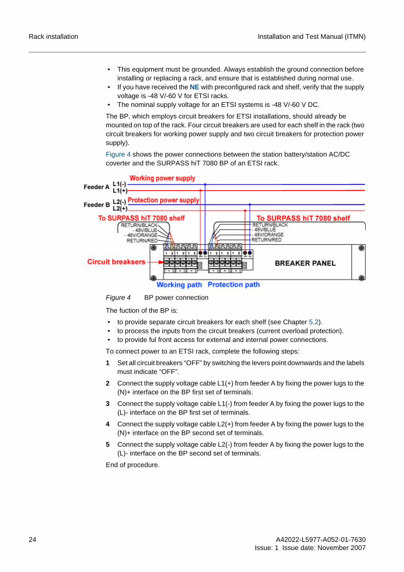
Figure 4 shows the power connections between the station battery/station AC/DC coverter and the SURPASS hiT 7080 BP of an ETSI rack.
Figure 4 BP power connection
The fuction of the BP is:
• to provide separate circuit breakers for each shelf (see Chapter 5.2). • to process the inputs from the circuit breakers (current overload protection). • to provide ful front access for external and internal power connections.
To connect power to an ETSI rack, complete the following steps:
1 Set all circuit breakers “OFF” by switching the levers point downwards and the labels must indicate “OFF”.
2 Connect the supply voltage cable L1(+) from feeder A by fixing the power lugs to the (N)+ interface on the BP first set of terminals.
3 Connect the supply voltage cable L1(-) from feeder A by fixing the power lugs to the (L)- interface on the BP first set of terminals.
4 Connect the supply voltage cable L2(+) from feeder A by fixing the power lugs to the (N)+ interface on the BP second set of terminals.
5 Connect the supply voltage cable L2(-) from feeder A by fixing the power lugs to the (L)- interface on the BP second set of terminals.
End of procedure.

A42022-L5977-A052-01-7630Issue: 1 Issue date: November 2007
25
Installation and Test Manual (ITMN) Shelf installation
5 Shelf installationThis chapter provides the necessary procedures for installing/removing, grounding and establishing power connection to the ETSI shelves.
This chapter is only performed if one of the following conditions is verified:
• The NE is not shipped in rack and shelf preconfiguration delivery format. • Replacing faulty shelves. • Adding extension shelves. • Establishing a power connection to a shelf.
All racks and ancillary equipment (e.g. power distribution devices, grounding facilities, fiber management devices, etc.) are installed according to local site plan.
For information regarding the possible arrangements of NE shelf mounting, explana-tions and detailed connections diagrams, pinning maps, electrical cabling, routing and cable lengths, refer to the Interconnect, Cabling and Mechanical Assembly (ICMA) manual.
5.1 Installing/Removing and grounding of shelvesThis procedure describes the necessary steps to properly install, or remove, and ground a SURPASS hiT 7080 shelf.
Installing shelves
g 1. Prior to installing the SURPASS hiT 7080 shelf, install the fire safety tray first. For information on fire safety tray installation, please refer to Chapter 7.1.
2. The SURPASS hiT 7080 shelf is pre-installed with the Nokia Siemens Networks ETSI shelf bracket. To install the shelf in the standard ETSI rack, follow the pro-cedure in Chapter 7.9 to mount the standard ETSI shelf bracket before the shelf installation.
To install a shelf, complete the following steps:
1 Mount the mounting nuts on the ETSI racks.
• For the standard ETSI rack, the mounting nut positions are on the 3rd, 13th, 15th, 17th, 19th, 21st, 23rd, and 25th mounting bolt hole counting from the bottom of the rack (see Figure 6).
• For the Nokia Siemens Networks ETSI rack, the mounting nut positions are on the 3rd, 13th, 17th, 21st, 25th, 29th, 33rd, and 37th mounting bolt hole counting from the bottom of the rack (see Figure 6).
2 Mount the shelf support bracket to the ETSI rack by tightening all M6 screws, make sure they are not over tightened and they will be removed after installing the shelf.
The mounting position of the shelf support bracket is on the 3rd mounting bolt hole counting from the bottom of the rack.
Figure 5 illustrates the shelf support bracket mounted on the rack.
!Warning:
The SURPAS hiT 7080 shelf is a rack mounted equipment, and it can not be used as a floor standing equipment.

26 A42022-L5977-A052-01-7630
Issue: 1 Issue date: November 2007
Installation and Test Manual (ITMN)Shelf installation
Figure 5 Shelf support bracket with rack
3 Remove the front cover of the shelf to be installed (if applicable).
4 Remove the fan units from the shelf if the fan units are pre-installed in the shelf.
Please refer to Chapter 7.6 for removing the fan units.
5 Slide the shelf into the rack, and place the shelf onto the shelf support bracket.
6 Mount the shelf in the required rack by tightening all M6 screws, and make sure they are not over tightened.
The lowest shelf bracket bolt hole should be mounted on the 13th mounting bolt hole of the rack.
7 Re-install the fan units to the shelf.
Please refer to Chapter 7.6 for installing the fan units.
8 Re-install the front cover and bolt it securely (if applicable).
9 Remove the shelf support bracket by removing the screws used for tightening the shelf support bracket to the rack and pulling out the shelf support bracket.
Figure 6 shows a SURPASS hiT 7080 shelf example mounted on the ETSI rack.

A42022-L5977-A052-01-7630Issue: 1 Issue date: November 2007
27
Installation and Test Manual (ITMN) Shelf installation
Figure 6 SURPASS hiT 7080 shelf with ETSI rack
End of procedure.
Removing shelves
To remove a shelf from the rack, complete the following steps:
1 Remove the front cover of the shelf (if applicable).
2 Disconnect power supply from the BP to the shelf by removing the circuit breakers.
3 Remove the screws used for tightening the shelf to the rack.
4 Carefully remove the shelf from the rack.

28 A42022-L5977-A052-01-7630
Issue: 1 Issue date: November 2007
Installation and Test Manual (ITMN)Shelf installation
End of procedure.
Grounding shelves
The shelf grounding is only completed for a standard ETSI rack, the grounding of a Nokia Siemens Networks ETSI shelf is completed by simply mounting the shelf to the rack.
g Use 12 AWG or larger size of the protective grounding cable to ground shelves.
5.2 Establishing power connectionsThis procedure describes the necessary steps for proper installation of DC power and cables to the SURPASS hiT 7080 shelf and the steps for disconnecting the power cables from the SURPASS hiT 7080 shelf.
5.2.1 Establishing power connectionsKeep in mind the following warnings when installing power connections:
• Shut off the power from the power source before beginning to establish power con-nections.
• This equipment must be grounded. Always establish the ground connection before installing or replacing a shelf, and ensure that it is established during normal use.
• If you have received the NE with preconfigured rack and shelf, verify that the supply voltage is -48V/-60 V for the ETSI racks.
Two electrical cables are needed for the power connection of each shelf (working and protection). Each cable is 3 m long and has a 5-pin female connector (D-Sub 5w5) on one end and two T-Faston terminals at the other end. If the ETSI BP uses breakers > 25 A, it requires screw mount terminals instead of faston terminals.
Figure 7 shows the power connections between the BP of the rack and a shelf.
Figure 7 Power connection between rack and shelf
Before starting the power connection procedure verify that:

A42022-L5977-A052-01-7630Issue: 1 Issue date: November 2007
29
Installation and Test Manual (ITMN) Shelf installation
• All power connections to the shelf are protected with 20 A breakers (disconnect devices) using dedicated power feeding cables in working/protection path.
• The cable used to establish the electrical connections is 400-40-50136.
To connect power to a shelf, complete the following steps:
1 Ensure that all circuit breakers on the BP are open (switching the levers point downward and the labels indicate “OFF”).
2 Take the end with the two T-Faston terminals of the first cable and insert both con-nectors in the appropriate female, working path, connectors of the corresponding two circuit breakers for the main shelf (A1) on the BP as shown in Figure 8.
3 Take the end with the two T-Faston terminals of the second cable and insert both connectors in the appropriate female, protection path, connectors of the correspond-ing two circuit breakers for the main shelf (B1) on the BP as shown in Figure 8.
Figure 8 displays the power connections on the BP.
Figure 8 Power connection on BP
Repeat steps 1 to 3 for shelves 2 (A2/B2) and 3 (A3/B3) if necessary.
4 Close the circuit breakers on the BP (switching the levers point upward and the labels indicate “ON”).
5 Take the first power cable (working path) end with 5-pin female D-Sub connector and connect the red test lead of the voltmeter (positive voltmeter connector) to the left pin of the cable connector (A1). Connect the black test lead (negative voltmeter connector) to the right pin (A2) of the D-Sub connector.
Figure 9 displays the connections from the voltmeter to the D-Sub connector.
Figure 9 Connections for voltage measurement
30 A42022-L5977-A052-01-7630
Issue: 1 Issue date: November 2007
Installation and Test Manual (ITMN)Shelf installation
Measure the voltage and verify that the voltmeter reads between -40 V DC to -72 V DC. Repeat the measurement with the red test lead connected to the pin A5 and black test lead connected to the pin A4.
6 Take the second power cable (protection path) end with the 5-pin female D-Sub con-nector and connect the red test lead of the voltmeter (positive voltmeter connector) to the left pin of the cable connector (A1). Connect the black test lead (negative volt-meter connector) to the right pin (A2) of the D-Sub connector (see Figure 9).
Measure the voltage and verify that the voltmeter reads between -40 V DC to -72 V DC. Repeat the measurement with the red test lead connected to the pin A5 and black test lead connected to the pin A4.
Repeat step 1, and proceed to step 7.
7 Neatly route the two power cables from the BP to the connector panel, forming a strain-relief.
8 Connect the first power cable to the male D-Sub connector on the connector panel labeled POWER A, close its two circuit breakers, and verify that the fan unit is working. Afterwards, open the two circuit breakers again.
9 Connect the second power cable to the male D-Sub connector on the connector panel labeled POWER B, close its two circuit breakers, and verify that the fan unit is working. Afterwards, open the two circuit breakers again.
Repeat steps 1 to 9 for additional shelves in the same rack (if applicable), and leave all circuit breakers open until instructed otherwise (switching levers point downward and labels “OFF”).
End of procedure.
5.2.2 Disconnecting power connectionsTo disconnect the power from a shelf, complete the following steps:
1 Open the circuit breakers on the BP (switching the levers point downwards and the labels indicate "OFF").
2 Pull out the first power cable connector from the male D-Sub connector on the con-nector panel labeled POWER A.
3 Pull out the second power cable connector from the male D-Sub connector on the connector panel labeled POWER B.
End of procedure.
!Strictly follow the procedures below to prevent damaging the NE, and never pull out the power cable without opening the circuit breakers on the BP.
A42022-L5977-A052-01-7630Issue: 1 Issue date: November 2007
31
Installation and Test Manual (ITMN) Installing cards in shelf
6 Installing cards in shelfThis chapter provides the necessary information to install cards in a SURPASS hiT 7080 shelf.
For an overview of the different types of cards available, please refer to the Technical Description (TED) manual.
For information on rack arrangements, frame/shelf equipping, required electrical cabling and cable connections, please refer to the Interconnect, Cabling and Mechanical Assembly (ICMA) manual.
For information regarding cards locations in shelves, please refer to Chapter 3 for relevant information.
Before installing module cards, keep in mind the following warnings:
• Switch shelf power “OFF” before installing module cards (deactivate circuit break-ers).
• Always use an ESD wristband when installing module cards. Plug the wristband cable into the Electronic Bonding Point (EBP) jack located on the left side of the cable duct level and ensure the shelf assembly is properly grounded.
• All module cards must be inserted slowly and carefully to avoid damage. All cards are fitted with insertion and removal aids by two levers. To ensure proper positioning of the card and as a protection against ESD, two captive crosshead screws on the top and bottom card levers have to be tightened. Specific characteristics of the cards (geometry, mechanical coding, backplane connectors) guaranty easy plugging of the cards, and shall prevent any damage.
• Always tighten the two captive crosshead screws before inserting the next card. • Always insert one card at a time. Never attempt to simultaneously insert two or more
cards into the shelf. • When inserting a card, make sure both levers on the card are unlocked and open.
Never attempt to insert a card with a closed lever. • Never apply excessive force when installing a card, otherwise severe damage can
occur to the card and the shelf:– If a card seems to require unusual effort to insert, do not force the entry.– If anything is physically interfering with card insertion do not force the entry.– If a card is not correctly engaging the shelf guide rails or backplane connector
do not force the entry. • Carefully close and lock the card levers only after the card is fully inserted and
properly seated in the backplane connector. Close both levers at the same time. • A filler panel must be installed for any empty slot in a shelf.
Figure 10 shows a module card example in a side and front view.

32 A42022-L5977-A052-01-7630
Issue: 1 Issue date: November 2007
Installation and Test Manual (ITMN)Installing cards in shelf
Figure 10 Side and front view of a module card (8 x STM-4/1)
It is mandatory that a plugged card is immediately fixed to the shelf with the supplied screws, it is not possible to install more cards if this task is not properly completed.
g The Compact Flash (CF) card should be installed in the SC card before installing the SC card in a shelf. Please refer to Chapter 7.8 for CF card installation.
6.1 Installing module cardsTo install a module card, identify the correct slot location in the shelf and complete the following steps:
1 Open and unlock the levers on the card.
2 Carefully slide-in the module card, and make sure each card mates properly with its backplane connector.
Carefully close both levers at the same time, and ensure that the levers are secure.
3 To fix the card position mechanically and to ensure ESD shielding, use the appro-priate cross-tip screwdriver to tighten the captive crosshead screws on the upper and the lower end of the faceplate (see Figure 10).
End of procedure.
6.2 Removing module cardsTo remove a module card, complete the following steps:
1 Use the appropriate cross-tip screwdriver to unscrew the captive crosshead screws on the upper and the lower end of the faceplate.
2 Open and unlock the levers on the card.
3 Carefully remove the module card without applying excessive force.
End of procedure.

A42022-L5977-A052-01-7630Issue: 1 Issue date: November 2007
33
Installation and Test Manual (ITMN) Installing additional equipment
7 Installing additional equipmentThis chapter provides the necessary procedures for installing additional hardware for the SURPASS hiT 7080 NE.
For detailed information on the equipment, please refer to the SURPASS hiT 7080 Tech-nical Description (TED) manual.
7.1 Fire safety trayThe fire safety tray is intended for fire resistance and combustion.
Figure 11 illustrates a fire safety tray for Nokia Siemens Networks ETSI rack.
Figure 11 Fire safety tray for Nokia Siemens Networks ETSI rack
One fire safety tray for each rack is required. Install the fire safety tray according to the number of racks installed on site.
To install the fire safety tray, complete the following steps:
1 Mount the mounting nuts on the ETSI racks.
The mounting nut positions are on the 1st and 2nd mounting bolt holes counting from the bottom of the ETSI racks (see Figure 6).
2 Mount the fire safety tray in the required rack by tightening all M6 screws, and make sure they are not over tightened.
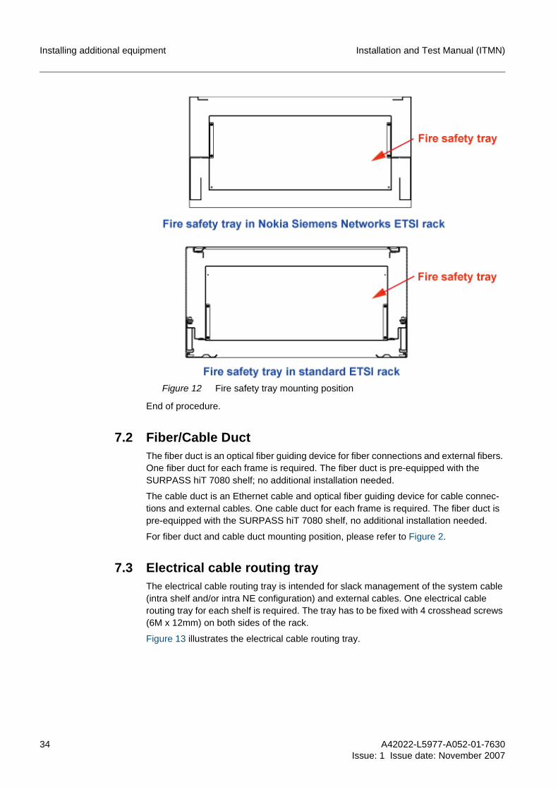
Figure 12 illustrates the fire safety tray mounted on the ETSI racks.
34 A42022-L5977-A052-01-7630
Issue: 1 Issue date: November 2007
Installation and Test Manual (ITMN)Installing additional equipment
Figure 12 Fire safety tray mounting position
End of procedure.
7.2 Fiber/Cable DuctThe fiber duct is an optical fiber guiding device for fiber connections and external fibers. One fiber duct for each frame is required. The fiber duct is pre-equipped with the SURPASS hiT 7080 shelf; no additional installation needed.
The cable duct is an Ethernet cable and optical fiber guiding device for cable connec-tions and external cables. One cable duct for each frame is required. The fiber duct is pre-equipped with the SURPASS hiT 7080 shelf, no additional installation needed.
For fiber duct and cable duct mounting position, please refer to Figure 2.
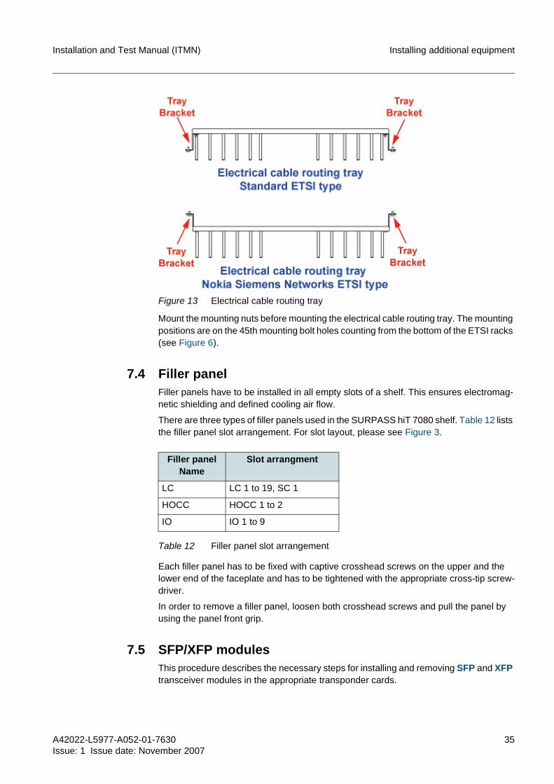
7.3 Electrical cable routing trayThe electrical cable routing tray is intended for slack management of the system cable (intra shelf and/or intra NE configuration) and external cables. One electrical cable routing tray for each shelf is required. The tray has to be fixed with 4 crosshead screws (6M x 12mm) on both sides of the rack.
Figure 13 illustrates the electrical cable routing tray.
A42022-L5977-A052-01-7630Issue: 1 Issue date: November 2007
35
Installation and Test Manual (ITMN) Installing additional equipment
Figure 13 Electrical cable routing tray
Mount the mounting nuts before mounting the electrical cable routing tray. The mounting positions are on the 45th mounting bolt holes counting from the bottom of the ETSI racks (see Figure 6).
7.4 Filler panelFiller panels have to be installed in all empty slots of a shelf. This ensures electromag-netic shielding and defined cooling air flow.
There are three types of filler panels used in the SURPASS hiT 7080 shelf. Table 12 lists the filler panel slot arrangement. For slot layout, please see Figure 3.
Each filler panel has to be fixed with captive crosshead screws on the upper and the lower end of the faceplate and has to be tightened with the appropriate cross-tip screw-driver.
In order to remove a filler panel, loosen both crosshead screws and pull the panel by using the panel front grip.
7.5 SFP/XFP modulesThis procedure describes the necessary steps for installing and removing SFP and XFP transceiver modules in the appropriate transponder cards.
Filler panel Name
Slot arrangment
LC LC 1 to 19, SC 1
HOCC HOCC 1 to 2
IO IO 1 to 9
Table 12 Filler panel slot arrangement
36 A42022-L5977-A052-01-7630
Issue: 1 Issue date: November 2007
Installation and Test Manual (ITMN)Installing additional equipment
For information on the appropriate transponder equipment and cable/fiber routing, please refer to SURPASS hiT 7080 Interconnect, Configuration and Mechanical Assembly (ICMA) manual.
Before installing SFP/XFP transceiver modules keep in mind the following warnings:
• Always use an ESD wristband when installing SFP/XFP transceiver modules. Plug the wristband cable into the EBP jack located on the left side of the cable duct level and ensure the shelf assembly is properly grounded.
• All transceiver modules must be inserted slowly and carefully to avoid damage. • Never apply excessive force when installing an SFP/XFP transceiver module; oth-
erwise severe damage can occur to the module and to the card:– If an SFP/XFP module seems to require unusual effort to insert, do not force the
entry.– If anything is physically interfering with the SFP/XFP module insertion, do not
force the entry.– If an SFP/XFP module is not correctly engaging the card, do not force the entry.
• Carefully close and lock the card levers only after the card is fully inserted and properly seated in the backplane connector. Close both levers at the same time.
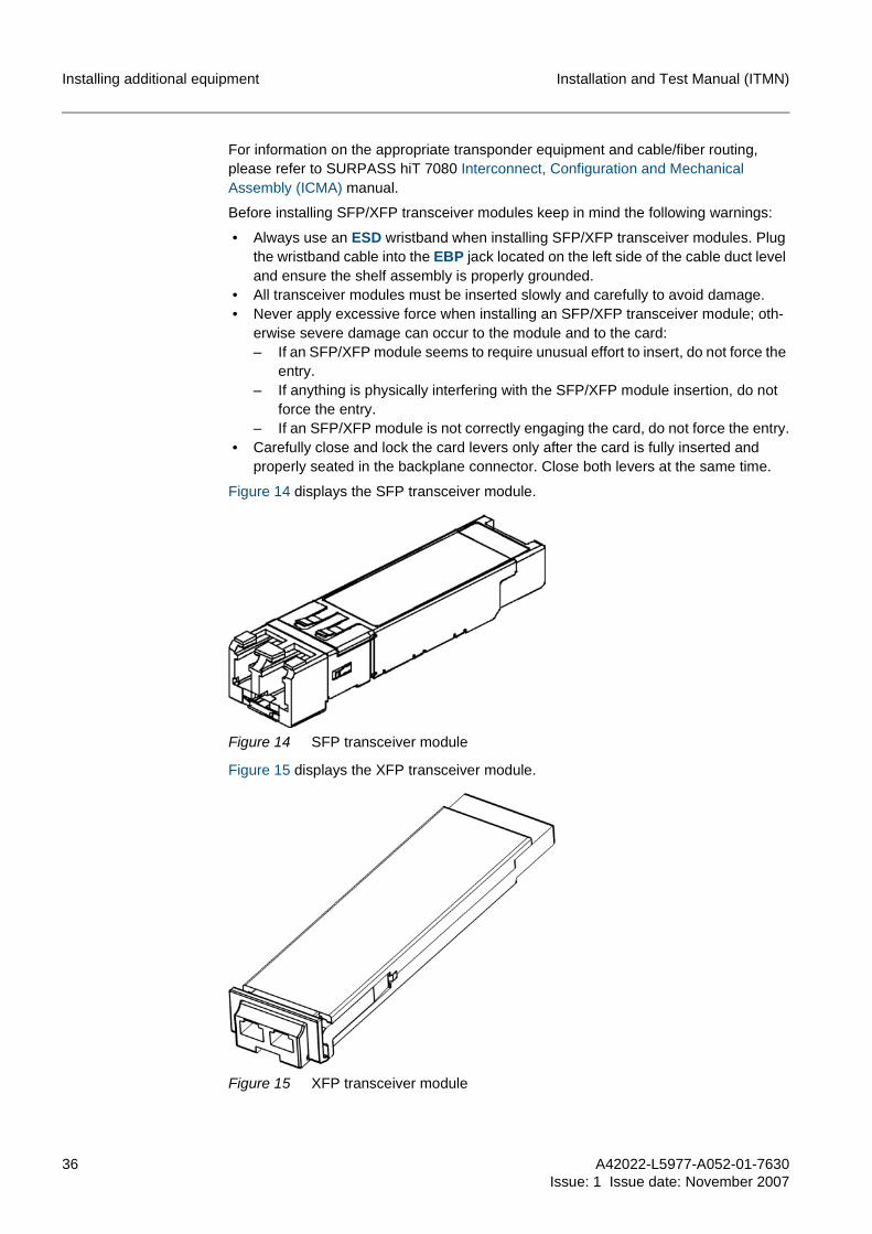
Figure 14 displays the SFP transceiver module.
Figure 14 SFP transceiver module
Figure 15 displays the XFP transceiver module.
Figure 15 XFP transceiver module

A42022-L5977-A052-01-7630Issue: 1 Issue date: November 2007
37
Installation and Test Manual (ITMN) Installing additional equipment
g The SFP and XFP transceiver modules are hot plugable. Shelf power shutdown or removing of the appropriate transponder card is not required.
Installing SFP/XFP transceiver module
Prior to installing the SFP/XFP modules, determine the slot location of the transponder card position in the corresponding shelf.
Additionally, make sure that the locking bracket is not positioned beside the module chassis.
To install an SFP/XFP module, and complete the following steps:
1 Align the module you are about to insert. Referring to the transponder card mounted in upright position the locking bracket has to be on the left module side.
SFPs/XFPs are keyed to prevent incorrect installation.
2 Insert the SFP/XFP module into the desired front slot of the appropriate transponder card. Make sure the locking mechanism has snapped in.
End of procedure.
Removing SFP/XFP transceiver module
To remove an SFP/XFP transceiver module, complete the following steps:
1 Remove the optical fibers connected to the transceiver module.
2 Turn bracket until it is positioned on the right side of the module chassis. This releases the locking mechanism on the module.
3 Slowly remove the module by pulling it slowly out of the transponder card slot. Using the locking bracket as a grip eases this procedure.
If it is not possible to take the locking bracket with your fingers, carefully use a small blade screwdriver to pull the bracket.
End of procedure.
Installing heat sink
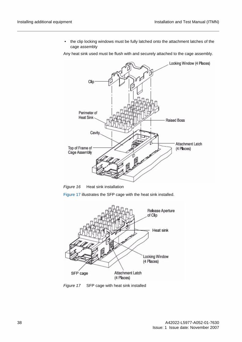
The heat sink is used for absorbing and dissipating heat from the SFP cage.
To install the heat sink, place the heat sink onto the SFP cage and secure the cage assembly by using the clip. After the heat sink and clip are installed, the following requirements must apply (see Figure 16):
• the perimeter of the heat sink must be flush with the top of the frame of the cage assembly
• the raised boss must be centered in the cavity of the cage assembly
!Warning:
For thermal insurance, before installing the 2.5 Gbps DWDM SFP or STM-64 SFP, make sure the heat sink has been installed in the SFP/XFP cage (see Figure 17). If not, follow the procedure in the Installing heat sink section to complete the heat sink instal-lation.
38 A42022-L5977-A052-01-7630
Issue: 1 Issue date: November 2007
Installation and Test Manual (ITMN)Installing additional equipment
• the clip locking windows must be fully latched onto the attachment latches of the cage assembly
Any heat sink used must be flush with and securely attached to the cage assembly.
Figure 16 Heat sink installation
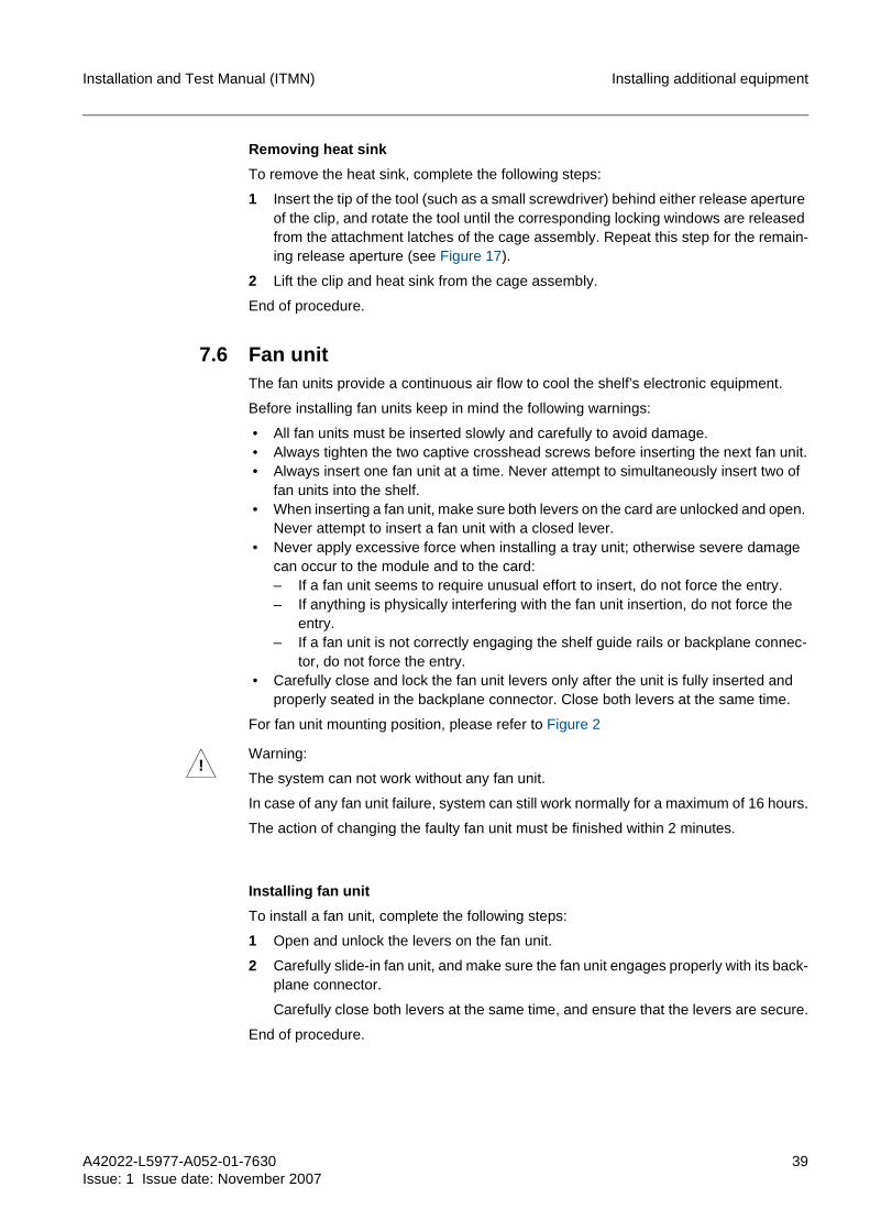
Figure 17 illustrates the SFP cage with the heat sink installed.
Figure 17 SFP cage with heat sink installed
A42022-L5977-A052-01-7630Issue: 1 Issue date: November 2007
39
Installation and Test Manual (ITMN) Installing additional equipment
Removing heat sink
To remove the heat sink, complete the following steps:
1 Insert the tip of the tool (such as a small screwdriver) behind either release aperture of the clip, and rotate the tool until the corresponding locking windows are released from the attachment latches of the cage assembly. Repeat this step for the remain-ing release aperture (see Figure 17).
2 Lift the clip and heat sink from the cage assembly.
End of procedure.
7.6 Fan unitThe fan units provide a continuous air flow to cool the shelf’s electronic equipment.
Before installing fan units keep in mind the following warnings:
• All fan units must be inserted slowly and carefully to avoid damage. • Always tighten the two captive crosshead screws before inserting the next fan unit. • Always insert one fan unit at a time. Never attempt to simultaneously insert two of
fan units into the shelf. • When inserting a fan unit, make sure both levers on the card are unlocked and open.
Never attempt to insert a fan unit with a closed lever. • Never apply excessive force when installing a tray unit; otherwise severe damage
can occur to the module and to the card:– If a fan unit seems to require unusual effort to insert, do not force the entry.– If anything is physically interfering with the fan unit insertion, do not force the
entry.– If a fan unit is not correctly engaging the shelf guide rails or backplane connec-
tor, do not force the entry. • Carefully close and lock the fan unit levers only after the unit is fully inserted and
properly seated in the backplane connector. Close both levers at the same time.
For fan unit mounting position, please refer to Figure 2
Installing fan unit
To install a fan unit, complete the following steps:
1 Open and unlock the levers on the fan unit.
2 Carefully slide-in fan unit, and make sure the fan unit engages properly with its back-plane connector.
Carefully close both levers at the same time, and ensure that the levers are secure.
End of procedure.
!Warning:
The system can not work without any fan unit.
In case of any fan unit failure, system can still work normally for a maximum of 16 hours.
The action of changing the faulty fan unit must be finished within 2 minutes.

40 A42022-L5977-A052-01-7630
Issue: 1 Issue date: November 2007
Installation and Test Manual (ITMN)Installing additional equipment
Replacing fan unit
To replace a fan unit, complete the following steps:
1 Open and unlock the levers on the fan unit.
2 Carefully remove the fan unit without applying excessive force.
3 Install a replacement fan unit.
End of procedure.
7.7 Air FilterDue to high air flow rates, an air filter is required to protect the shelf from environmental dust and other contaminants.
7.8 CF cardThe pluggable Compact Flash (CF) memory card is equipped in the SC card. The NE database, Management Information Base (MIB), system software, and configurations are stored in this nonvolatile memory card, which supports quick recovery in the event of power failure, node failure, or unit replacement.
Before installing module cards, keep in mind the following warnings:
• Always use an ESD wristband when installing the CF card into an SC card. Plug the wristband cable into the EBP jack located on the left side of the cable duct level and ensure the shelf assembly is properly grounded.
• Never apply excessive force when installing a CF card, otherwise severe damage can occur to the CF card and SC card.– If a CF card seems to require unusual effort to insert, do not force the entry.– If anything is physically interfering with card insertion, do not force the entry.– If a CF card is not correctly engaging the CF card slot or backplane connector,
do not force the entry.
Figure 18 displays the CF card slot position on the SC card.
!An excessively dirty air filter will reduce cooling airflow.
It is recommended that the air filter should be replaced every 3 months or more fre-quently if environmental conditions warrant.
The action of the air replacement must be finished within 10 minutes.

A42022-L5977-A052-01-7630Issue: 1 Issue date: November 2007
41
Installation and Test Manual (ITMN) Installing additional equipment
Figure 18 CF card slot position
Inserting CF card
To insert the CF card, complete the following steps:
1 Locate the CF card slot on the SC card (see Figure 18).
2 Make sure the CF card reject button is inside the button slot. If not, press the CF card reject button once to push it inside.
3 Insert a CF card into the CF card slot with the printed side facing the back of the SC card, and make sure the CF card engages properly with the backplane connector.
The CF card is keyed to prevent incorrect installation.
End of procedure.
Removing CF card
To remove the CF card, complete the following steps:
1 Press the CF card reject button one time to eject the button.
2 Press the CF card reject button again to pop out the CF card.
3 Take the CF card out of the card slot.
Do not attempt to pull out the CF card without using the card reject button.
End of procedure.
!Warning:
The only allowed CF card should be validated and provided by Nokia Siemens Net-works. Any CF card from another supply channel is forbidden and might cause system failure.

42 A42022-L5977-A052-01-7630
Issue: 1 Issue date: November 2007
Installation and Test Manual (ITMN)Installing additional equipment
7.9 Standard ETSI shelf bracketThe standard ETSI shelf bracket is used for the SURPASS hiT 7080 shelf installed in the standard ETSI rack.
To install the standard ETSI shelf bracket, complete the following steps:
1 Remove the Nokia Siemens Networks ETSI shelf bracket from the right side of the shelf by removing the five internal Torx screws used for mounting the shelf bracket, and keep the five screws for later use.
For the screw hole positions, please see Figure 19.
2 Mount the standard ETSI shelf bracket by tightening internal Torx screws.
Seven internal Torx screws are needed for one standard ETSI shelf bracket instal-lation. Use the five screws removed from the Nokia Siemens Networks shelf bracket and additional two screws which can be found in the equipment accessory package.
For the screw hole positions, please see Figure 19.
3 Repeat step 1 to step 2 for installing another standard ETSI shelf bracket on the left side of the self.
Figure 19 illustrates the shelf bracket mounting hole positions for the ETSI racks.
Figure 19 Shelf bracket mounting positions
End of procedure.

A42022-L5977-A052-01-7630Issue: 1 Issue date: November 2007
43
Installation and Test Manual (ITMN) Establishing cable connections
8 Establishing cable connectionsThis chapter contains the necessary information for establishing cable connections.
For more information on rack arrangement, card equipping, fiber handling rules, Ethernet cabling and fiber connections, please refer to the Interconnect, Cabling and Mechanical Assembly (ICMA) manual.
For information on safety and handling, please refer to the Safety Instructions manual.
In order to avoid cable damage when routing the cable connections, the following cable guiding parts of the system have to be used:
• Fiber duct: Supports safe fiber routing from rack to rack. The fiber duct system is mounted on bottom of the shelf.
• Cable duct: Supports safe Ethernet cable routing from rack to rack. The cable duct system is mounted on middle of the shelf.
• Electrical cable routing tray: Supports safe electrical cable routing from rack to rack. The electrical cable routing tray is mounted over the SURPASS hiT 7080 shelf.
Since the NE normally requires a lot of internal cable connections, it is reasonable to complete a cabling assembly sequence as follows:
1 Shelf internal cabling
2 Rack internal cabling
3 Rack external cabling
8.1 Client signal cable connectionsThe SURPASS hiT 7080 client signal cables include the following two cable types:
• Optical fiber • Ethernet cable
For more information, please see the corresponding section.
8.1.1 Optical FiberNokia Siemens Networks has several lengths of fiber patch-cords available for optical connections. Both ends of these patch-cords are terminated with an LC type fiber con-nectors. The recommended patch-cord lengths are listed in the ICMA manual.
In any case, such customer-supplied fiber cables must be terminated with the same type and quality of fiber connector as used on Nokia Siemens Networks cables and cards. Using different optical connectors will result in unacceptable optical performance. All optical connectors have to be LC type only.
Before establishing optical fiber connections, keep in mind the following warnings:
• Always use an ESD wristband when establishing fiber connections. Plug the wrist-band cable into the EBP jack located on the left side of the cable duct level and ensure the shelf assembly is properly grounded.
• Use extreme caution when connecting or disconnecting fiber, since high optical power levels can be present at card connectors or fiber ends. Never look directly into the end of a fiber, patch-cord, fiber pigtail, or card connector unitil you are sure that no light is present.
• Never make any fiber connections with dirty connectors.
44 A42022-L5977-A052-01-7630
Issue: 1 Issue date: November 2007
Installation and Test Manual (ITMN)Establishing cable connections
– The use of dirty connectors will most likely result in irreversible damage to fiber end faces and/or connector and unacceptable optical performance.
– If the faces of the optical connectors are dirty, it may cause attenuation and reflections which impair transmission quality severely.
For information on optical connector cleaning instruction, please refer to Chapter 6 in SURPASS hiT 7080 Troubleshooting Manual (TSMN).
• Always fit unused optical fiber connectors with protective caps to guard against mechanical damage and contamination. The protective dust caps should only be removed immediately prior to installation.
• Always use fiber protection wiring for safe fiber routing, please refer to Fiber protec-tion wiring section for more details.
• To remove fiber connection, always pull the connectors. Never pull the fibers.
SURPASS hiT 7080 uses LC connectors (SFP/XFP transceiver modules) to establish fiber connections. Each LC connector can be connected to two fiber connectors that are stacked on top of each other, the upper fiber and the lower fiber.
To install or remove the fiber connections, complete one of the following tasks:
Establishing fiber connection
To establish fiber connections, complete the following steps:
1 Connect the upper fiber connector to the upper slot in the LC connector in the tran-sponder card.
Assure that you heard the snap in sound.
2 Connect the lower fiber connector to the lower slot in the LC connector in the tran-sponder card.
Assure that you heard the snap in sound.
End of procedure.
Removing fiber connection
To remove the fiber connections, complete the following steps:
1 Press the lever of the upper fiber connector to release the fiber.
If it is not possible to press the lever with your finger, carefully use a small blade screwdriver with one hand to press the lever, and pull the connector with the other hand.
2 Press the lever of the lower fiber connector to release the fiber.
If it is not possible to press the lever with your finger, carefully use a small blade screwdriver with one hand to press the lever, and pull the connector with the other hand.
End of procedure.
Fiber protection wiring
Fiber protection wiring is used for protecting fibers routed in the rack against fiber damage. One fiber protection wiring can hold up to twenty fibers.
Figure 20 shows a bunch of fibers with fiber protection wiring surrounded.

A42022-L5977-A052-01-7630Issue: 1 Issue date: November 2007
45
Installation and Test Manual (ITMN) Establishing cable connections
Figure 20 Fiber protection wiring
8.1.2 Ethernet cableSURPASS hiT 7080 uses Category 6 (CAT 6) Ethernet cable with RJ 45 connectors to establish electrical Ethernet connections. If the transmission distance is over 10 meters, use the pin arrangement recommended in Table 13.
Before establishing Ethernet cable connections, keep in mind the following warnings:
• Always use an ESD wristband when establishing Ethernet cable connections. Plug the wristband cable into the EBP jack located on the left side of the cable duct level and ensure the shelf assembly is properly grounded.
• To remove Ethernet cable connection, always pull the connectors. Never pull the cables.
Figure 21 shows the RJ 45 male connector.
Figure 21 RJ 45 male connector
Table 13 lists the pin assignment of RJ 45 male connector.

46 A42022-L5977-A052-01-7630
Issue: 1 Issue date: November 2007
Installation and Test Manual (ITMN)Establishing cable connections
Table 14 lists the CAT 6 Ethernet cable color code for wiring RJ 45 connector.
To install or remove the Ethernet cable connections, complete one of the following tasks:
Establishing Ethernet cable connection
To establish Ethernet cable connections, complete the following steps:
1 Determine the routing path of the Ethernet cable connection.
2 Cut the connection cable to the appropriate length and add RJ 45 male connectors to the cable ends.
3 Plug one RJ 45 male connector of the patch-cord into the corresponding Ethernet interface.
If you hear a “Click”, the RJ 45 connector has engaged and the connection is secure.
4 Plug the RJ 45 male connector of the opposite end of the path-cord to the corre-sponding Ethernet interface.
If you hear a “Click”, the RJ 45 connector has engaged and the connection is secure.
End of procedure.
Removing Ethernet cable connection
To remove the Ethernect cable connection, press the lever of the RJ 45 male connector to release the cable.
8.2 Controller cards connectionsThe SURPASS hiT 7080 controller cards include the following two types:
• System Controller (SC) cardFigure 22 displays the faceplate of the SC card.
PIN Number Signal Name
1 Twisted-pair, Tx+
2 Twisted-pair, Tx-
3 Twisted-pair, Rx+
4 Not Connected
5 Not Connected
6 Twisted-pair, Rx-
7 Not Connected
8 Not Connected
Table 13 Ethernet cable RJ 45 connector pin assignment
1 2 3 4 5 6 7 8
White Orange
Orange White Green
Blue White Blue
Green White Brown
Brown
Table 14 Category 6 twisted pair color code standard

A42022-L5977-A052-01-7630Issue: 1 Issue date: November 2007
47
Installation and Test Manual (ITMN) Establishing cable connections
Figure 22 SC faceplate
• System Interface with EOW function (SI-E) cardFigure 23 displays the faceplate of the SI-E card.
Figure 23 SI-E faceplate
For detailed information on controller card faceplate interfaces, pinning, cabling and routing, please refer to SURPASS hiT 7080 Interconnect, Configuration and Mechanical Assembly (ICMA) manual.For detailed information on the controller cards please refer to the SURPASS hiT 7080 Technical Description (TED) manual.Before establishing controller card connections, always connect the grounding wrist wrap strap to the ground jack on the shelf connector panel. This prevents static dis-charge from damaging the equipment.
8.2.1 SC cardThe SC card provides one CONSOLE interface (RS 232) for NE initialization access. The Console cable uses DB9 connectors at each end.
To establish the console cable connection, complete the following steps:
1 Connect one end of the console cable to the console interface on the SC card, and tighten the captive crosshead screws on both end of the DB9 connector.
The console cable is provided in the SURPASS hiT 7080 installation kit.
2 Connect the other end of the console cable to the COM port on the PC, and tighten the captive crosshead screws on both end of the DB9 connector.
End of procedure.
8.2.2 SI-E cardThe SI-E card provides the following interfaces:
• Timing interfaces (T3-1, T3-2, T4-1, T4-2) • Alarm interface (ALM) • Extended user channel interfaces (HCOC-1, HCOC-2) • Engineering Order Wire interface (EOW)
The EOW interface can be used to establish conference and selective calls from one NE to other NEs via an EOW handset using a 2-wire RJ 45 handset interface on the SI-E card faceplate.
!Warning:
To reduce the risk of fire, use No.26 AWG or larger telecommunication line cord only.

48 A42022-L5977-A052-01-7630
Issue: 1 Issue date: November 2007
Installation and Test Manual (ITMN)Establishing cable connections
• Management interfaces (MGT-1, MGT-2)The management interfaces provide external controller card access. Specifically it’s used for connections to Telecommunication Network Management System (TNMS) and Local Craft Terminal (LCT) simultaneously.Connections are established via two RJ 45 connectors on the faceplate of the SI-E card.
• Extension shelf interfaces (EXT-1, EXT-2. EXT-3, EXT-4)The extension shelf interfaces provide four 100 Mbps Ethernet channel for commu-nication between main shelf and extension shelves.
g The extension shelf interfaces are reserved for a future product release. • F1 user channel interfaces (F1-1, F1-2) • MDO interfaces (MDO1-4, MDO5-8) • MDI interfaces (MDI1-4, MDI5-8)
CAT 6 Ethernet cable with RJ 45 connectors are used for all interface connections.For pin assignments, please refer to SURPASS hiT 7080 Interconnect, Configura-tion and Mechanical Assembly (ICMA) manual.
!Warning:
It is forbidden to loop the two management (MGT-1 and MGT-2) ports or connect them to the same hub, since the management packets are always sent out from the two management ports so that it may effect the system performance.
!Warning:
The voltage of MDI is -48V. The MDI cable only can be inserted into MDI interface. Inserting MDI cable into other interfaces can cause SC card damage.
A42022-L5977-A052-01-7630Issue: 1 Issue date: November 2007
49
Installation and Test Manual (ITMN) Abbreviations
9 AbbreviationsACO Alarm Cut Off
ACT Active
AWG American Wire Gauge
BP Breaker Panel
BOA Booster Optical Amplifier
CAT Category
CF Compact Flash
DC Direct Current
DCN Data Communication Network
EBP Earth Bonding Point
EMI Electromagnetic Interference
EOW Engineering Order Wire
ESD Electrostatically Sensitive Device
ETSI European Telecommunications Standards Institute
EXT Extension
GND Ground
HOCC High Order Cross Connection
ICMA Interconnect, Cabling and Mechanical Assembly manual
ID Identifier
ITMN Installation and Test Manual
LC Lucent Connector
LCT Local Craft Terminal
LED Light Emitting Diode
LOM List Of Mertial
MAC Media Access Control
MDI Miscellaneous Discrete Input
MDO Miscellaneous Discrete Output
MGT Management
MIB Management Information Base
NE Network Element

50 A42022-L5977-A052-01-7630
Issue: 1 Issue date: November 2007
Installation and Test Manual (ITMN)Abbreviations
NSN Nokia Siemens Networks
PC Personal Computer
POA Pre-Optical Amplifier
PWR Power
SC System Controller
SDH Synchronous Digital Hierarchy
SFP Small Form-Factor Pluggable
SI System Interface
SI-E System Interface with Engineering Order Wire
SU System Unit (1 SU = 25 mm)
SUP Suppress
TED Technical Description manual
TNMS Telecommunication Network Management System
TSMN Troubleshooting Manual
XFP 10 Gbps Small Form-Factor Pluggable
A42022-L5977-A052-01-7630Issue: 1 Issue date: November 2007
51
Installation and Test Manual (ITMN)
Index
AAdditional equipment 22
Air filter 40Cable duct 34CF card 40Electrical cable routing tray 34Fan unit 39Fiber duct 34Filler panel 35Fire safety tray 33SFP 35Standard ETSI shelf bracket 42XFP 35
CCable
Ethernet cable 45Optical fiber 43
Cable connectionConsole cable 47Ethernet cable 46Optical fiber 44
CardInstalling cards 31Removing cards 32Supported cards 21
CF cardInserting CF card 41Removing CF card 41
Controller cardSC card 47SI-E card 47
DDelivery format 14Document structure 9
FFan unit
Installing fan unit 39Replacing fan unit 40
Fire safety trayInstalling fire safety tray 33
GGrounding
Shelf 28
HHeat sink
Installing heat sink 37Removing heat sink 39
IInstalling
Cards 31CF card 41Fan unit 39Fire safety tray 33heat sink 37Rack 23SFP 37Shelf 25Standard ETSI shelf bracket 42XFP 37
OOptical fiber
Fiber protection wiring 44
PPin assignment
RJ 45 45Power connection
Rack 23Shelf 28
RRack 16
Grounding rack 23Installing rack 23Power connection 23
RemovingCards 32CF card 41Ethernet cable 46Heat sink 39Optical fiber 44SFP 37Shelf 27XFP 37
ReplacingFan unit 40
RequirementDocumentation 13Environment 12Staff 12Tools and equipment 11
52 A42022-L5977-A052-01-7630
Issue: 1 Issue date: November 2007
Installation and Test Manual (ITMN)
SSFP
Installing SFP 37Removing SFP 37
Shelf 18Disconnecting power connection 30Establishing power connection 28Grounding shelf 28Installing shelf 25Power connection 28Removing shelf 27Slot arrangement 20
XXFP
Installing XFP 37Removing XFP 37