angular velocity - windrock
TRANSCRIPT

Angular Velocity
The Analysis of the RPM

Physics
• The rate of change of angular displacement and is a vector quantity which specifies the angular speed of an object and the axis about which the object is rotating.

Simplified
• The RPM displayed in a 0 to 360/720 degree plot and measured degree-by-degree so that slight RPM changes can be detected.

Angular Velocity’s Sensor Point
• Records the rise and fall of the RPM in a phased plot
• Can record in units of RPM and Hz • Only requires the encoder

Angular Velocity’s Tools
• Derivatives and Spectrum window• Smoothing • Cursor• Group/Waterfall Plots
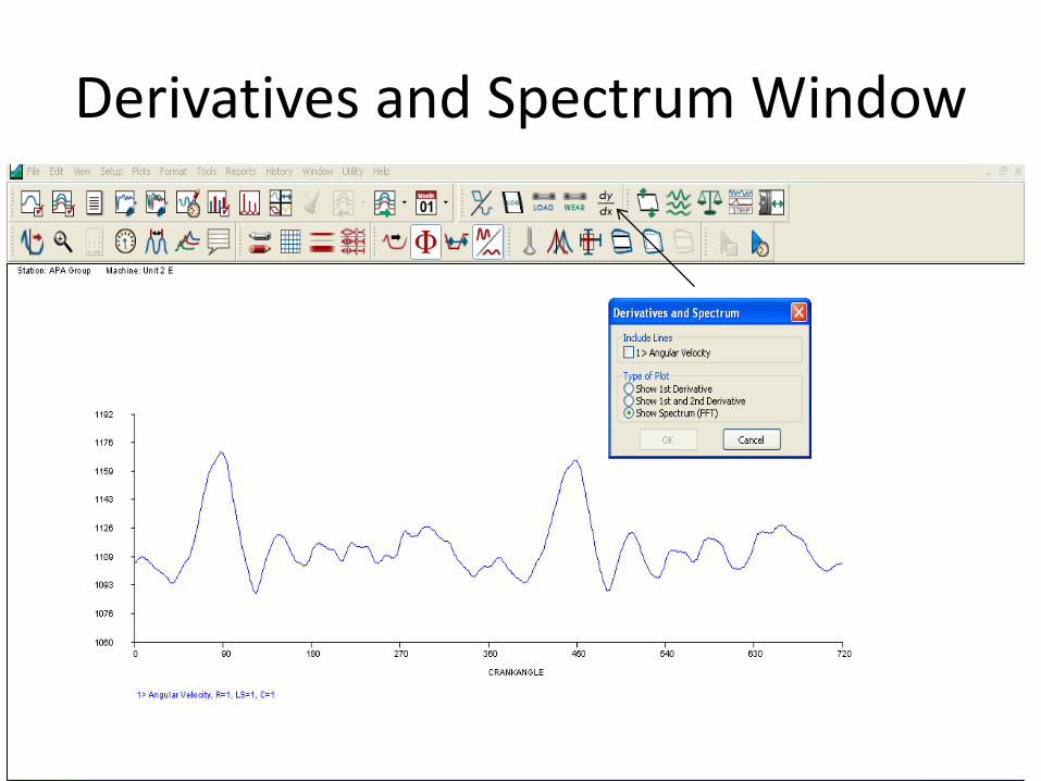
Derivatives and Spectrum Window

Change to an FFT Plot
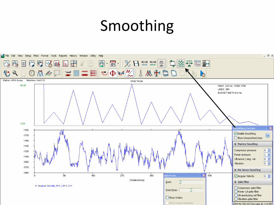
Smoothing

Cursor

Plots

Why Use Angular Velocity?
• Some OEMs will recommend maximum peak RPM in a revolution, aka RPM Velocity Limit
• Crankshaft Torsional Vibration• Alternating torques are generated by the slider-
crank mechanism of the crankshaft, connecting rod, and piston.
• The motion of the piston mass and connecting rod mass generate alternating torques, often referred to as "inertia" torques.
• The cylinder pressure due to combustion is not constant through the combustion cycle.
• The slider-crank mechanism does not output a smooth torque, even if the pressure is constant (e.g., at top dead center there is no torque generated).

Continue • Machines with several cylinders can have very flexible
crankshafts due to their long length. • There is inherently little damping in a crankshaft to reduce the
vibration.• If torsional vibration is not controlled in a crankshaft, it can
cause failure of the crankshaft or any accessories that are being driven by the crankshaft (typically, at the front of the machine, the inertia of the flywheel normally reduces the motion at the rear of the machine).
• This potentially damaging vibration is often controlled by a torsional damper that is located at the front nose of the crankshaft (in automobiles, it is often integrated into the front pulley).
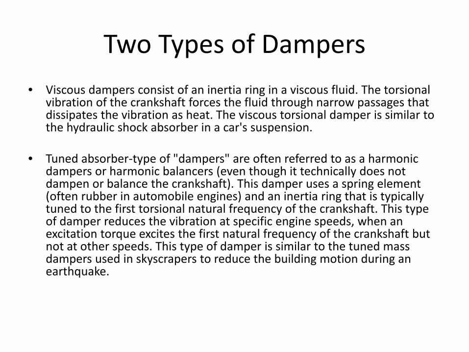
Two Types of Dampers• Viscous dampers consist of an inertia ring in a viscous fluid. The torsional
vibration of the crankshaft forces the fluid through narrow passages that dissipates the vibration as heat. The viscous torsional damper is similar to the hydraulic shock absorber in a car's suspension.
• Tuned absorber-type of "dampers" are often referred to as a harmonic dampers or harmonic balancers (even though it technically does not dampen or balance the crankshaft). This damper uses a spring element (often rubber in automobile engines) and an inertia ring that is typically tuned to the first torsional natural frequency of the crankshaft. This type of damper reduces the vibration at specific engine speeds, when an excitation torque excites the first natural frequency of the crankshaft but not at other speeds. This type of damper is similar to the tuned mass dampers used in skyscrapers to reduce the building motion during an earthquake.
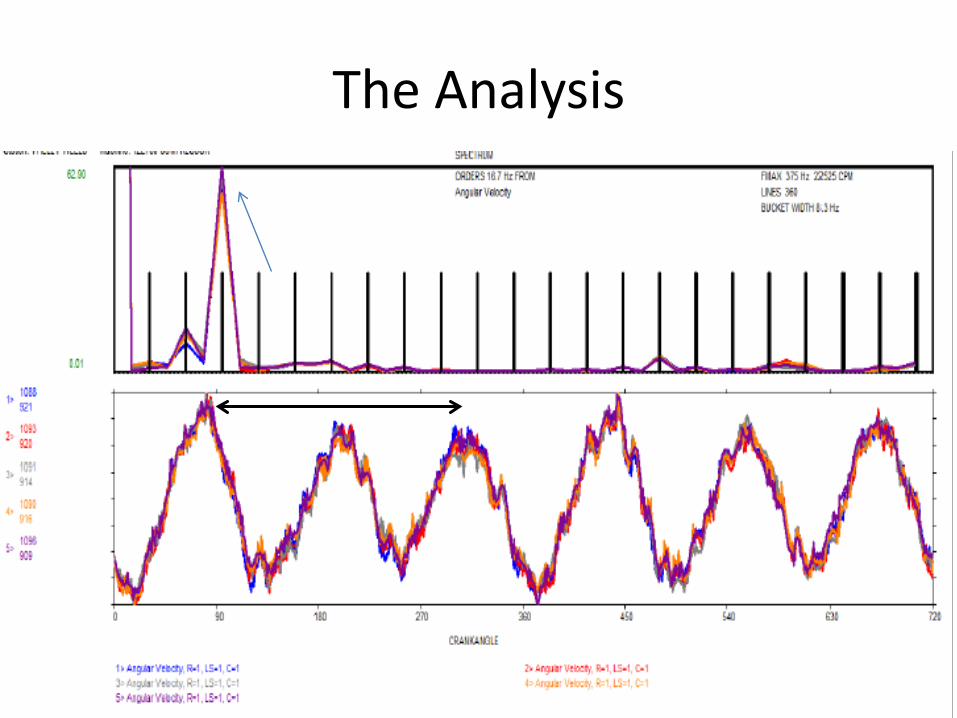
The Analysis

FFT, Guidelines and Trending

Be Careful

Due Diligence
• Garbage in, garbage out!– Encoder must be rigid, straight and free of
obstacles– Plastic and rubber should not be used in the
coupling or the tip of the encoder– Best Results would be a hex head bolt and socket
or something comparable

Angular Velocity Example(hex head drive on a TLA 6 at 289 RPM)
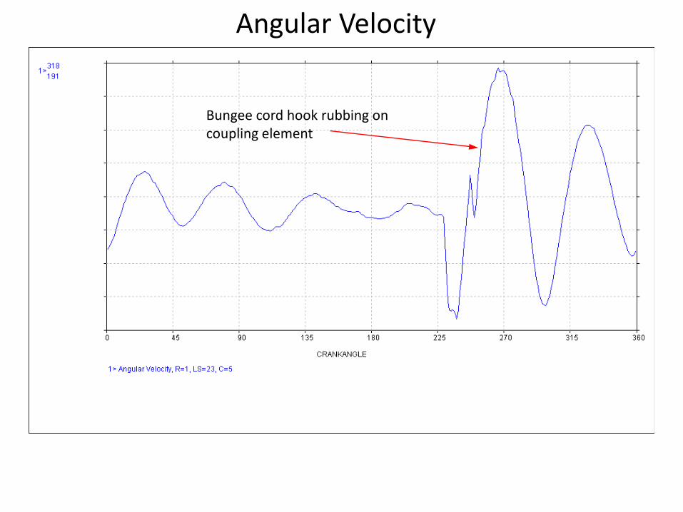
Angular Velocity
Bungee cord hook rubbing on coupling element
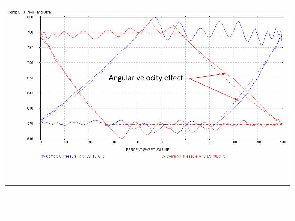
Angular velocity effect

Conclusion
• Upside– The test point is very easy to collect– The analysis is easy if coupled to FFT data and/or
guidelines
• Downside– There is some startup preparation needed
• Machine may need to be down to install a hex head/bolt
– Torsional issues are rare
Questions?