angular velocity measurement using an undamped gyroscope
TRANSCRIPT

NPS ARCHIVE1959MORROW, C.
ANGULAR raOCITY MEASUREMENT
USING AN UNDAMPED GYROSCOPE
CHARLES D. MORROW

U.S. NAVAL POSTGRADUATE SCHOOL
MONTEREY, CALIFORNIA


ANGU1 fiR VELOCITY MEASURE bl^T USING
AD UNDAMPED GYROSCOPE
Charles D. Morrow


ANGULAR VELOCITY MEASUREMENT USING
AN UNDAMPED GYROSCOPE
by
Charles D. Morrow
Lieutenant, United States Navy-
Submitted in partial fulfillment of therequirements for the Completion of Course
GUIDED MISSILE CURRICULUM
United States Naval Postgraduate SchoolMonterey, California
19 5 9

\
c\cbc\
ANGULAR VELOCITY MEASUREMENT USING
AN UNDAMPED GYROSCOPE
by
Charles D. Morrow
This work is accepted as fulfilling the
thesis requirements for the Completion of Course
GUIDED MISSILE CURRICULUM
United States Naval Postgraduate School


ABSTRACT
Gyroscopes in their various forms have been used as
references for moving bodies. This is an investigation
of a proposed gyro to be used as an angular velocity
detector; the gyro and associated servo to be a component
of a computer for application to a missile guidance system.
A scheme for using single degree of freedom undamped gyros
on individual platforms is described; the gyro character-
istics are analysed. A scheme for using the proposed gyro
on a stablized platform is analysed.
The writer wishes to express his appreciation for the
assistance and advice given him by Professor M. L. Cotton
of the U. S. Naval Postgraduate School, Messrs. Glynn
Lockewood, and Albert Chanowitz of the Dalmo Victor
Engineering Company, and Lieutenant C. R. Watts, United
States Navy.
The analysis was accomplished by Charles D. Morrow,
Lieutenant, United States Navy during an industrial exper-
ience tour of duty with the Dalmo Victor Engineering
Company, 1515 Industrial Way, Belmont, California, and
Dalmo Victor Research Engineering Laboratory, 462 Jefferson
Street, Monterey, California.
ii


TABLE OF CONTENTS
Section Title Page
1. Introduction,
1
2. General Considerations • 1
3. Single Platform System 5
4. Steady State Response, Single Platform 11
5. Gyro Performance 15
6. Stable Element 17
7. Steady State Response, Stable Element 20
8. Stability 20
9. Results 26
10. Conclusions 27
11. Bibliography 28
iii


LIST OF ILLUSTRATIONS
Figure Page
1. Gyro, Single Platform 2
2. Yaw System 6
3. Mitrovic Chart T = 0.3; SinglePlatform System 9
4. Gyro Frequency Resnonses 16
5. Yaw System - Stable Element 19
6. Mitrovic Chart J = 0.3; Stable Element 21
7. Nichol's Chart 24
B. Frequency Response; Yaw System 25
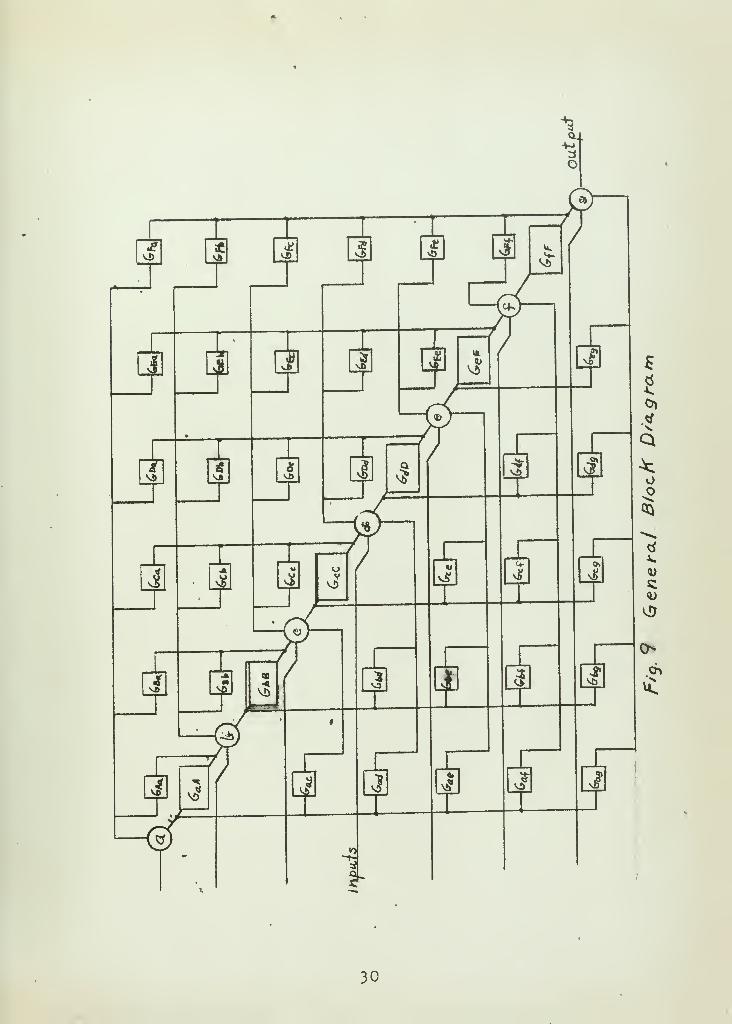
9. General Block Diagram 30
IV

1. Introduction
This investigation resulted from a proposal to use a
gyroscope as a component of a missile guidance system.
The construction of the gyro was to be such that the cost of
production would be between that of aircraft gyro instru-
ments and the well known HIG gyro.
Input velocities were to be measured by having the
gyro output signal amplified and used to activate a servo-
motor to drive the platform at a velocity equal in magnitude
but opposite in direction to that of the input. The plat-
form velocity would then be used in a computer to compute
Dosition from an initial reference.
The Minneapolis-Honeywell Company has done a similar
investigation, using the HIG gyro. The Minneapolis-
Honeywell Company was primarily concerned with drift. This
analysis is an investigation of stability.
2. General Considerations,
Angular motion of a missile may be measured by fixing
the sensitive (input) axis of three single degree of free-
dom gyros along the roll, pitch and yaw axes of the missile.
The measurements are then made in terms of p,q,and r the
angular rate of motion relative to the body axis.


These rates are related to a fixed inertial reference
frame by the transformation
roll
pitch
yaw
Cos <p - 5^4>
«
smcpsece Cos<J>sec&
X
/°
9*
h
(1)
Either set of angles describe the rotational motion of
missile. *
It is convenient in the analysis to use velocities
referred to inertial space (A,B,C).
> The problem may be expressed by J\U - U/n -t CJa
for each gyro where A60 is the net angular velocity to
which t,he gyro is sensitive; (Jin the input velocity with
respect to inertial space and Up the platform rate. The
simplified diagram of Fig. 1 shows the physical arrange-
ment of one of the platforms.
// rR/',
///
///////////*
pi*off -*-T«T
jC/f/ss//e Fra.me.
Fiff. 1


The direction of the angular displacement of the motor
from the null position is best described by the vector cross»
product.
Ti? = TTxAU (2)
The differential equations describing a gyro and its
associated servo platform are
1.% 4 °e ?= Abacas!* Aco t ti*w5 (3)
Equation (3) is the sum of torques at the gyro output axis
and equation (4) the sum of torques at the platform axis.
The parameters of the system for initial analysis,
were estimated to be
I - 2000 gm cm 2
g1
- xu rad/sec
• h>
= 1200 gm cm 2.
V = 10 dyT\ejcm --1U rad/sec
H = ^S I S = 3xl06 Z™e
™2

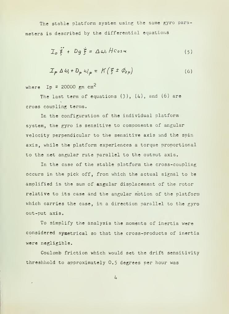
The stable platform system using the same gyro para-
meters is described by the differential equations
lof + Ddt = Au.Heos* (5)
IfAty + DpKJ,^ K(?±&p) (6)
where Ip = 20000 gm cm2
The last term of equations (3), (4), and (6) are
cross coupling terms.
In the configuration of the individual platform
system, the gyro is sensitive to components of angular
velocity perpendicular to the sensitive axis and the spin
axis, while the platform experiences a torque proportional
to the net angular rate parallel to the output axis.
In the case of the stable platform the cross-coupling
occurs in the pick off, from which the actual signal to be
amplified is the sum of angular displacement of the rotor
relative to its case and the angular motion of the platform
which carries the case, in a direction parallel to the gyro
out-put axis.
To simplify the analysis the moments of inertia were
considered symetrical so that the cross-products of inertia
were negligible.
Coulomb friction which would set the drift sensitivity
threshhold to approximately 0.5 degrees per hour was

estimated to be /Oy/l£
. This parameter wasrcLd/sec.
neglected in the analysis.
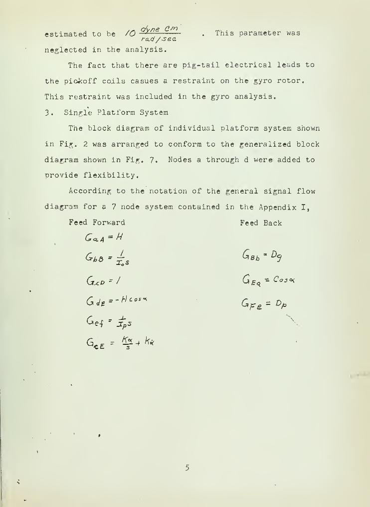
The fact that there are pig-tail electrical leads to
the picikoff coils casues a restraint on the gyro rotor.
This restraint was included in the gyro analysis.
3. Single Platform System
The block diagram of individual platform system shown
in Fig. 2 was arranged to conform to the generalized block
diagram shown in Fig. 7. Nodes a through d were added to
provide flexibility.
According to the notation of the general signal flow
diagram for a 7 node system contained in the Appendix I,
Feed Forward Feed Back


tf\
to
M
*

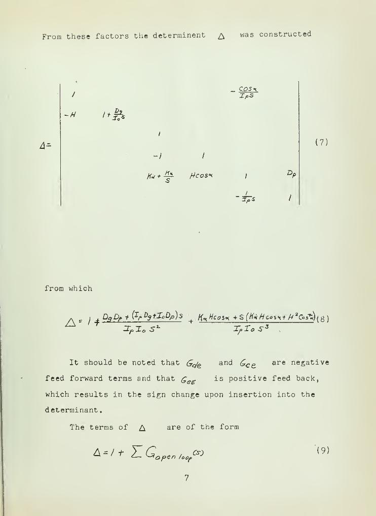
From these factors the determinent £ was constructed
A=-
/
-I
fa + ill /4cosi
XpS
Z/oS
(7)
from which
a s /. D<fD/>i'(Ir D3+I°Dp)s
—'-ft Mo 5 j,r^ J
It should be noted that G<fe an& Gj?e are neSat i ve
feed forward terms and that Qe£ is positive feed back,
which results in the sign change upon insertion into the
determinant
.
The terms of A are of the form
A = /+ HGoptnUt oi (9)

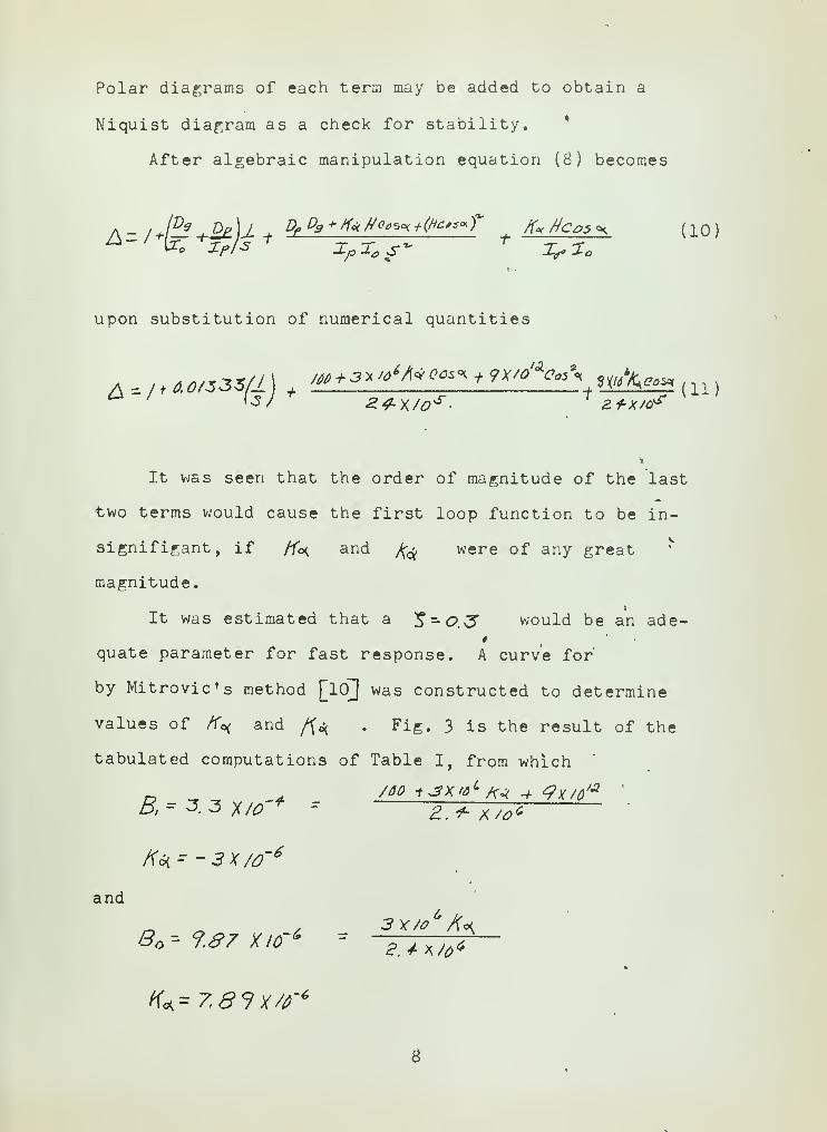
Polar diagrams of each term may be added to obtain a
Niquist diagram as a check for stability. *
After algebraic manipulation equation (8) becomes
a - / JEl ,Op)j Dr D9 + /<<k ffffsg+(Hc**«T /fee tico$ «h (10)
upon substitution of numerical quantities
It was seen that the order of magnitude of the last
two terms would cause the first loop function to be in-
signifigant, if /fo< and /^ were of any great
magnitude.
It was estimated that a ^-O.^? would be an ade-*
quate parameter for fast response. A curve for'
by Mitrovic's method [lOj was constructed to determine
values of K^ and /fa . Fig. 3 is the result of the
tabulated computations of Table I, from which
A* - -3X/0'6
and
S '- <?.87 xicr* -a.**/**
—K*=7.8?X/f4


TABLE I
U)h Bo Bl
0.5xl0"2 0.259xlO"6 o.ao6xio-4
0l7xl0~ 2 0.44SxlO~6 1.247X10"4
0.9xlO* 2 0.543xlO-6 1.713x10⁻⁴
l.OxlO" 2 0.733xlO"6 1.970x10⁻⁴
1.2xlO" 2 O.SS5xlO-6 2.522x10⁻⁴
1.4xl0-2 0.973xlO"6 3.121xlO" 4
l.gxlO" 2 O.S30xlO"6 k.KlOxlO"1*
2.0xlO*"2 0.530xlO"
65.226x10"^
2.2xlO" 2 O.lOOxlO"6
6.025x10⁻⁴
2.4xl0" 2 -0.600xlO'6 6.390x10⁻⁴
10

These values were chosen such to take the maximum
advantage of amplifier and torque motor gain. It was noted
that the system is stable, constrained thus by Mitrovic's
method, however to achieve the stability, the sign of the
term associated with A^ must be changed, and that the
signal from the angular Dosition pick-off must be atten-
uated. The changing of sign in the /f^ amplifier
would cause the closed loop function to have zeros in the
right half of the s-plane. It was observed that the torque
associated with the (//co5«<) term was a torque caused by
cross coupling and that its direction was dependent upon
the net rotation of the platform about the gyro output
axis, with respect to inertial space.
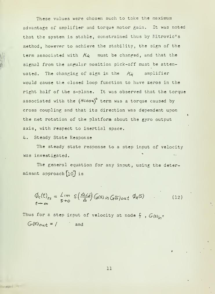
4. Steady State Response
The steady state response to a step input of velocity
was investigated. '•
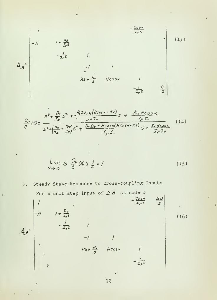
The general equation for any input, using the deter-
minant approach [loj is
<fcft)„= L,m s(^)Q(s)/yiQsjolit 0«(S) (12 ,
Thus for a step input of velocity at node £, Q(s)- -
G(s)oa.t =/ and
11

*cA
-H
I
2o*
-/
K**^ //cos*
Cos>x
- /
IpSc_
3
(13)
5?+ ^5 -/-»-: *- 5 "f
a —T/>2< 2>Z«
S -H—*• ** z=-)S t*""
-> ' -r <
(U)
(15)
5. Steady State Response to Cross-coupling Inputs
For s unit step input of AS at node a
/
CoS* A63
-/•/Dg
V/
/
-/ /
1
**£ //cos* 1
V
/
(16)
12


and
4fc)»A B
(17)
thus CJt)=Um 5XS/M^(S) =AB«
for small angles of o< .
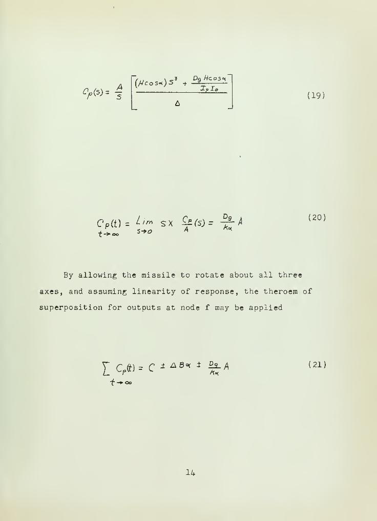
For a unit step input of A at node d
V s
/
-/
ft* (k Hcos* I
ZoS
A5
(IB)
13
%

fy(s) =A5
(/VcoS-<)S + —2——
(19)
Cp(t) = ^"» SX £*fe)r "^t->,
s-»<2
(20)
By allowing the missile to rotate about all three
axes, and assuming linearity of response, the theroem of
superposition for outputs at node f may be applied
Y_CPtt)= C * AB °< * %A (21)
14

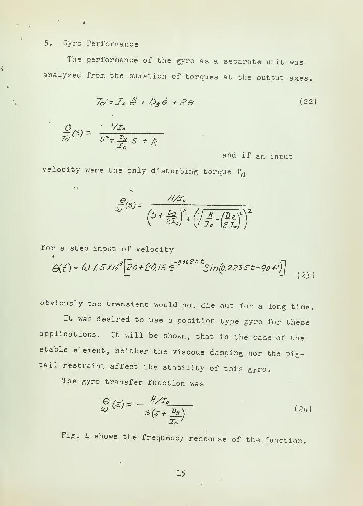
5. Gyro Performance
The performance of the gyro as a separate unit was
analyzed from the sumation of torques at the output axes.
Tc/'Jo S * Ds o + fte (22)
& ,-v - '/&
and if an input
velocity were the only disturbing torque Td
*o>.
for a step input of velocity
(23)
obviously the transient would not die out for a long time.
It was desired to use a position type gyro for these
applications. It will be shown, that in the case of the
stable element, neither the viscous damping nor the pig-
tail restraint affect the stability of this gyro.
The gyro transfer function was
S /c) - H/r*
Fig. 4 shows the frequency response of the function.
15


^-^v.^% M16


The transient response to a step input velocity was
Q(t) * (J X3X//tsxv-3tie' °°St
-/J (25)
It was noted that in both cases the transient was of
extremely long duration, and non-linear.
6. Stable Element
It was decided to investigate a stablized platform
configured so as to use the undamped gyro.
Without facilities for simulation of all three degrees
of freedom, it proved impractical to obtain an analysis, so
only a single degree of freedom with no cross-coupling
was considered. ^ Since the gyro was to be mounted on a
platform, 20000 dyne-cm2 was chosen as a representative
magnitude of the platform moment of inertia about the inner
gimbal axis.
Under the conditions of no cross-coupling and con-
sidering only one degree of freedom, the block diagram of
the stabilized platform and the single degree of freedom
platform are the same, except for the torque caused by the
net rotation about the gyro output axis. Cross-coupling
in this system occurs in the pick-off due to the motion
of the motor element relative to the case, and the case
rotating about the output axis due to rotations of the
platform about the output axis. Mayer 7 demonstrates
that within certain limitations there is an optimum orien-
tation of the gyros for the reduction of oscillation
17


Fig. 2 represents a dual pick-off stable platform,
when the cross-coupling inputs are eliminated and the feed
forward Dath from nodes d to e removed. By so doing node d
was eliminated and the system becomes a five node system
where
A =
/CoS<*
IpS
-H /-Si
1
/
%/r* s 1 Dp
t 2>s /
(26)
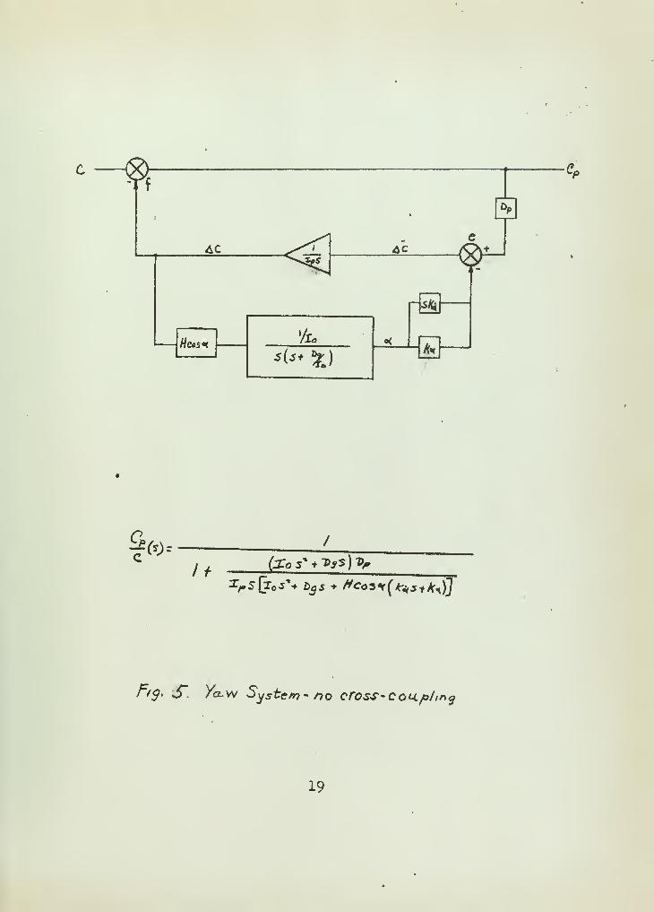
The system shown in Fig. 5, by block diagram reduction
had a system function
c£.
C(S) =
/
/ + fca* * D3 s)Op(27)
Zps(z Ss+{)9 s) + //co5^(^ + *«*)
It was seen that this was a unity feed forward system,
a fact not obvious when the open loop function was derived
by the determinent method. By deleting each one of the
pickoffs in turn there are two other possible configurations
Q-<S) = ^ To s
s 3 w^ -+ Ec)
s
2 + 2£_£^ s + ^ //cc35o<
X, ZpJ""
jrp I l^lj
(28)
18

"f
'
4C ^f. AC /C^*^5gf T
~Aty
'A. o<Hcos*-An</ <* Oa/ \5(5+ £ /
ffc>
/>5>. J" /a.w System- no cross- coup/my
19


ands2+-B* 5 + ** "cos «
c<.z+ft>s + Df>\<? £>sdp + fo Hcos +
(29)
3^plo
It was considered that the use of the rate pick-off
alone would be inadviseable due to the difficulty of
measuring the small velocities involved.
The system described by equation (29) is undesireabl
due to having zeros in the right half of the s-plane.
Thus it was chosen to work with the dual pickoff system.
Where
Qp.(S) =
Io\
tp x<
e
C ^3 , /Do DP \ _ 2 nQ n„ ,«. Ka Hr-***, 1? TTT—— (30)
7. Steady State Response
The steady state response to a unit step function ofvelocity was
cP (t) = L><" svOefavC -/
#. Stability
A Mitrovic chart, Fig. 6, was made using the char-
acteristic equation of the dual nick-off system. From which
20


mm
21


/f = 91 2 X^' &fa = 7#* fd
~*
The curve for ^=0.3 was chosen on the estimate
that it would yield the fastest response.
It was plain that these figures for A^ and A^ were
unsatisfactory.
By raising the gain of /f^ and A^ by an amount
great enough to make the coefficients of the sz term
insignifigant and dropping the factor D$ op for the same
reason the characteristic equation became
* e/ r££? + ^^>K*H K*H (32)
for small angles.
The form of the last two terms suggested that the system
could use phase lead compensation. A double network of the
form
was chosen, then
.4*5 + 1 )(sr +,J^-5^
22

K
'
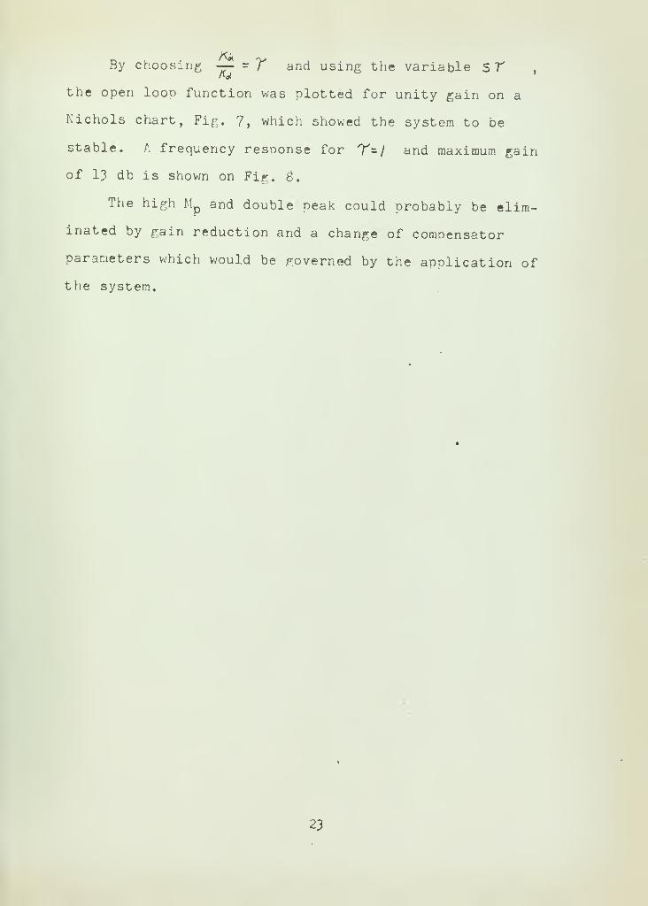
By choosing —- s Y and using the variable STthe open loon function was plotted for unity gain on a
Nichols chart, Fig. 7, which showed the system to be
stable. A frequency response for T=/ and maximum gain
of 13 db is shown on Fig. 3.
The high M and double peak could probably be elim-
inated by gain reduction and a change of compensator
parameters which would be governed by the application of
the system.
23


Pha.se angle.
-/6Z
r/g. f/V/cAo/s Chart for compzhsxtttd Sysfe/rj
2k


25


9. Results
1. The system of individual platforms will follow
all inputs if inputs are maintained long enough. Cross-
coupling inputs could be subtracted from any platform
motion output in a computer.
2. At low gain the stable element system is con-
ditionally stable.
'
3; Any gyro drift will be reproduced as a platform
motion.
k. The friction damping and pigtail restraint have
negligible effect on the stability of the stable element.
5. The gyroscope response is extremely slow.
6. The stable platform, will be stable if the ampli-
fier gain is properly adjusted for the range of frequency
of operation.
7. Detecting and amplifying the time rate of change
of the gyro precession angle, reduces the requirement for
phase lead compensation.
g. The frequency response of the stable element in-
dicates an adequate bandwidth.
9. The frequency response of the gyro indicates large
attenuation at the higher frequencies.
26

10'. Conclusions:
1. A greatly increased platform velocity damping would
speed up the response of the individual platform system.
2. Increasing the velocity damping of the gyro would
improve the linearity of the gyro output and reduce the
transient more quickly.
3. There is an advantage to be had by utilizing the
time rate of change of precession angle in that less com-
pensation is required to achieve stability.
4. If the attenuation of the gyro output signal at
higher frequencies and the non-linearities of the transient
can be tolerated the use of the gyro in a stable platform
is feasable.
5. The damping of the gyro and platform have little
to do with the stability of the inertial platform, but do
degrade the form of the gyro output signal.
27

' BIBLIOGRAPHY
1. Richard F. Deimel, Mechanics of the Gyroscope, DoverPublications, inc., 1950.'
2. Charles Stark Draper, Walter McKay, Sidney Lees, M.I.T.Instrument Engineering, Vol. I, McGraw-Hill BookCompany, Inc., 1952.
3. Kearfott Company, Inc., Gyros, Technical Informationfor the Engineer, March, 1957.
4. Philip J. Klass, Inertial Guidance, Aviation Week, 1957.
5. Luther Manufacturing Co., Electronic Instrument Components.
6'
fn\!!;iMan
£na11
;Ri
|id Body Equations of Motion For Usein Analog Computer Studies of Symmetrical Spinning
Missiles, E.A.I. Computation Center, March, 1957.
7# T^r!*ayer
'Anal ysis of Gyro Orientation, I.R.E.Transaction on Automatic Control, Dec, 195B.
6' Half LMX
n^ KrinC
^i?S °f Automatic Control, Prentice-nan, inc., October, 1953.
9. J. B. Scarborough The Gyroscope, Theory and ApplicationInterscience Publishers, Inc., 1953.application,
10#' 2!??£! L Thale
f;»Advanced Linear and Nonlinear Compen-sation Theory, U.S. Naval Postgraduate School, 195™.
U" uT fiL^i T
5al
fr
'Advanced Li"«ar Servomechanism TheoryU.S. Naval Postgraduate School, 1957.
y »
12# ^K G *. TrUMai J Automatic Feedback Control SystemSynthesis, McGraw-Hill Book Company, Inc., 1955?
13' TnirfLfp
51!7
'R°Sf
r B-W^d bury, John Hovorka,Inertial Guidance, M.I.T. 1957.
'
U'
McGr;wWHilj
e'RnnCV
AdVanCedxEnsineerinS Mathematics,incuraw-Hill Book Company, Inc.k 1951.
15' ScienJfir
ifn
arTS0^. Th
? ^roscoP« Applied, Hutchinsons
LtdTLlito^\lr^nlCal ?Ublications
»Cheltenham Press
16' kertical°?htr
haraCTP^f iCS and Stabilization of an
N^vI^L^ Rif'J?E Transactions on Aeronautical andNavigational Electronics, Vol. ANE 5, June 1953.
28


appendix i
The characteristic equation was developed by arranging
the system to conform to the general block diagram and
setting up an array
c d e
A
B
G
D
E
a b
Feed-forward terms
Feed-back terms(1)
The numerator of the closed loop function is the
product ^Cfr bjLj where At^ is the minor of the column i
associated with the input node and j is the row associated
with the desired output node.
29

30


APPENDIX II
The Mitrovic method curves \l6] were obtained
from the generalized equation:
4= «>*+-- + q,s f ac (1)
Let 5- - fUJn -+JUA, //- ~SZ
After substitution (1) may be written as two
simultaneous equations since the summation of reals
and imaginaries must go to zero independently, then
Let B1
- ai, B = a
B = -<oh az 0) t a*k)n gW- - - q*uj*\M (2)
a= a.uj^^ta.co^p)---- +cth tin~'0Jl) C3)
^=-2^.,(J)t h_ 2W „*2 (4)
The location of point M at coordinates (B^B )
enclosed by the ~5 = curve define stability limits.
31


LIST OF SYMBOLS
1. ^ j Q Gyro angle output
2. U) tj 2 3 Velocity along three orthogonal axes
3
.
<$ZjoAngular position with respect to inertialspace of a platform, in the directionof the gyro output axis.
4. Td Disturbance torque
5. R Restraint on gyro caused by electrical leads
32


thesM839
Angular velocity measurement using an un
ll!llllllllll|l!!lllllllllllll!lllllllll
3 2768 001 91724 8DUDLEY KNOX LIBRARY
flRHn(JUhKshmHI
$
{liihufru
It*! I J. !. / i '
{IhltlilliWrlllW
liPflliili rilull
llllllliliijIIJlllllnirUl
i iili i -i« p'ii
lilflHllpntiuliUi'
' •.
'
J'
'
;
!
'
' ;>'
'.''
llillj
IS SI
''.'' '''.''I
'
;;