aneutronic fusion spacecraft architecture
TRANSCRIPT

Aneutronic Fusion Spacecraft Architecture
A. G. Tarditi1, G. H. Miley2 and J. H. Scott3
1University of Houston – Clear Lake, Houston, TX 2University of Illinois-Urbana-Champaign, Urbana, IL
3NASA Johnson Space Center, Houston, TX
NIAC 2012 – Spring Meeting, Pasadena, CA
Aneutronic Fusion Spacecraft Architecture
A. G. Tarditi1, G. H. Miley2 and J. H. Scott3
1University of Houston – Clear Lake, Houston, TX 2University of Illinois-Urbana-Champaign, Urbana, IL
3NASA Johnson Space Center, Houston, TX
NIAC 2012 – Spring Meeting, Pasadena, CA
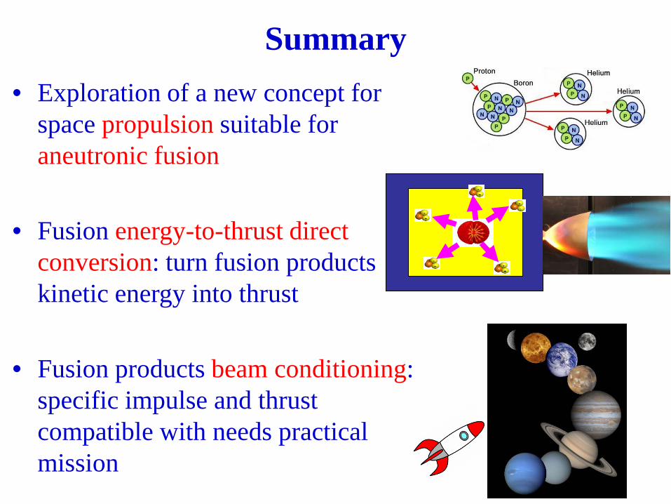
• Exploration of a new concept for space propulsion suitable for aneutronic fusion
• Fusion energy-to-thrust direct conversion: turn fusion products kinetic energy into thrust
• Fusion products beam conditioning: specific impulse and thrust compatible with needs practical mission
Summary
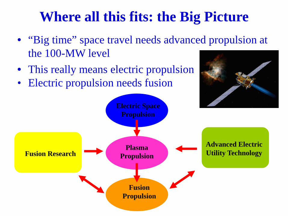
Where all this fits: the Big Picture
Fusion Research
Electric Space
Propulsion
Fusion
Propulsion
Plasma
Propulsion
• “Big time” space travel needs advanced propulsion at the 100-MW level
• This really means electric propulsion • Electric propulsion needs fusion
Advanced Electric Utility Technology
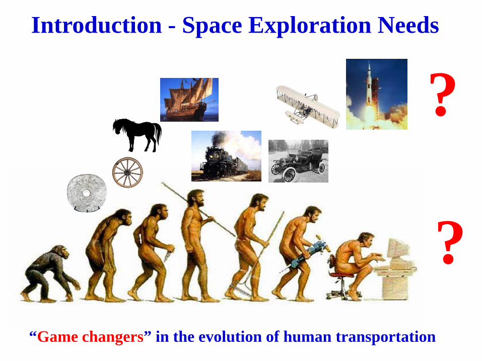
Introduction - Space Exploration Needs
“Game changers” in the evolution of human transportation
?
?
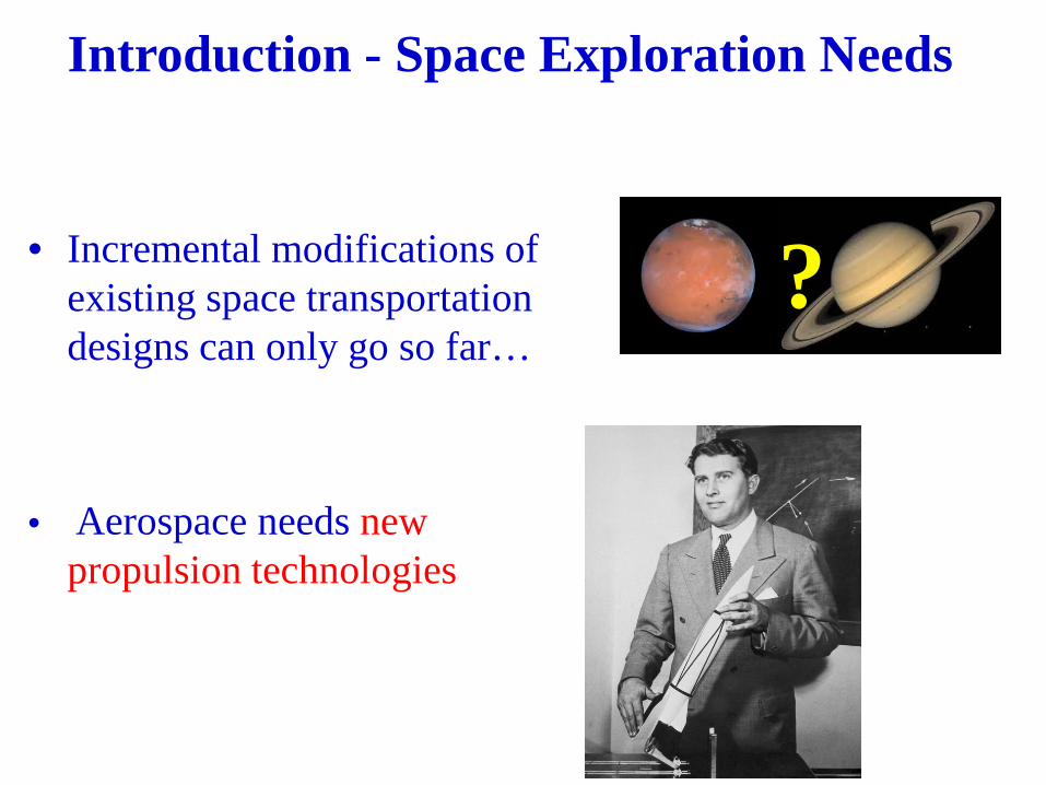
Introduction - Space Exploration Needs
• Incremental modifications of
existing space transportation designs can only go so far…
• Aerospace needs new propulsion technologies
?

• A new propulsion paradigm that enables faster and longer distance space travel is arguably the technology development that could have the largest impact on the overall scope of the NASA mission
• In comparison, every other space technology development would probably look merely incremental
• Investing in R&D on new, advanced space propulsion architectures could have the largest impact on the overall scope of the NASA mission.
Introduction - Priorities
• Utilization of fusion energy for spacecraft propulsion may be one of the most compelling research directions for the development of the future space program
• Fusion research has reached a high level of scientific and technological maturity through a half-century of remarkable progress
Introduction – Fusion Propulsion

• Even if a fusion reactor were to be available today, its successful application to space propulsion would be constrained by the requirements of integration with an electric thruster
• Overall system mass and efficiency is ultimately all that matters if a significant step-change in the potentials of space travel is to be achieved
• Key figure of merit: specific mass α [kg/kW]
Introduction – Fusion Propulsion
• Design a spacecraft architecture that, for a given payload, enables the most capable missions
• Focus on minimal overall system specific mass α (kg/kW)
• Choose highest energy density source (fusion is just second to matter-antimatter annihilation) and…
• …a propulsion scheme with a minimal-mass and highest-efficiency in propellant acceleration
Motivation

Ideal Space Propulsion
• Utilize fusion products directly for production of thrust
• The most efficient propulsion system will utilize the highest energy density source and the simplest propulsion configuration
Low-Mass Fusion Core
Fusion Products Exhaust

Fusion Propulsion
? Fusion Reactor Plasma Jet Thrust
Ideal case:
Light fusion core => Fusion Products => Exhaust
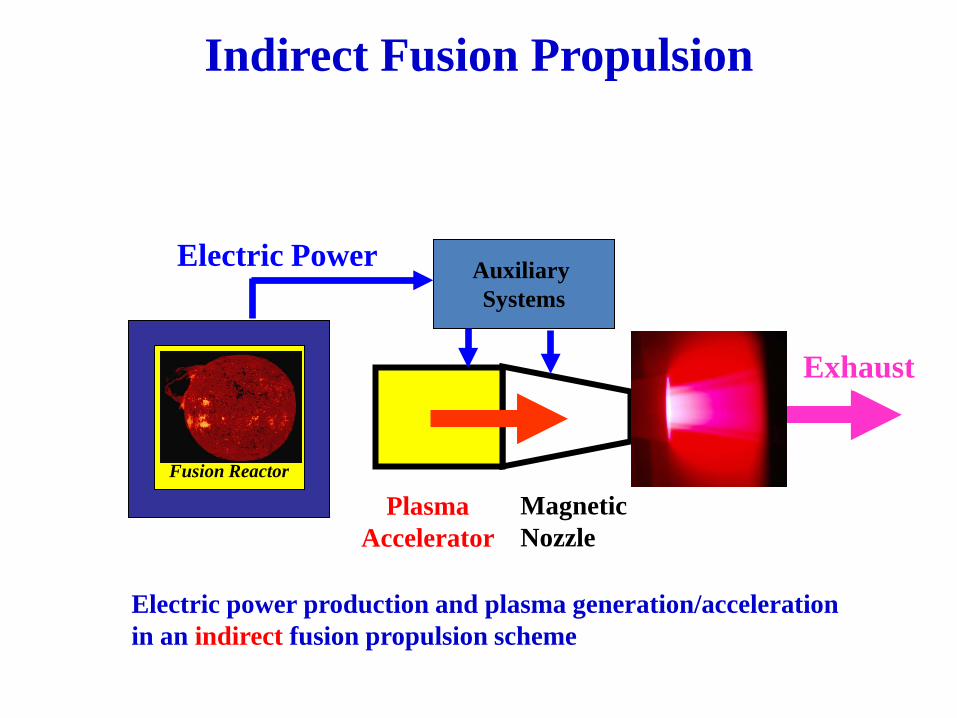
Indirect Fusion Propulsion
Electric power production and plasma generation/acceleration in an indirect fusion propulsion scheme
Plasma Accelerator
Auxiliary Systems
Electric Power
Magnetic Nozzle
Exhaust
Fusion Reactor

Auxiliary Systems
Fusion Reactor Beam Conditioning
System Exhaust
Fusion Products Beam
Direct Fusion Propulsion
Plasma exhaust production in a direct fusion propulsion scheme
Electric Power
Mission Design
• For a given mission and given power and initial mass, there is an optimal specific impulse profile that allows the fastest transfer
• In the gravity-free approximation, it can be shown that the optimal specific impulse (Isp) is proportional to the trip time (shorter trips will require more thrust, less Isp) [Moeckel, 1972]
• For “reasonable” travel in the Solar System the optimal Isp is in the 104 s range
W. E. Moeckel, J. Spacecraft, 6 (12), 863 (1972) and NASA-TN D-6968 (1972)
Aneutronic Fusion
• Fusion products from main aneutronic reactions: – p + 11B => 3 4He +8.7 MeV – 2.9 MeV α-particle ’ speed ≈107 m/s (simplification:
each α-particle is considered having an energy of 2.9 MeV)
• D + 3He => p (14.7 MeV) + α (3.7 MeV) – 3.7 MeV α-particle ’ speed ≈1.3· 107 m/s – 14.7 MeV proton ’ speed ≈ 5.3·107 m/s
• These reactions give a specific impulse in the 106 s range; too high for most practical purposes

Basic Constraints
• A jet of particles (beam) with velocity v and a mass flow equal to dM/dt (kg/s)
• (Momentum) Thrust Fth=v (dM/dt) • The specific impulse is conventionally expressed in
seconds and defined as Isp=v/g0 , where g0 is the Earth gravity acceleration
• Then, for a given power, to decrease the Isp and increase the thrust at the same time the mass flow needs to be increased
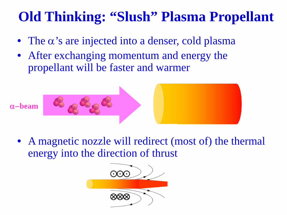
Old Thinking: “Slush” Plasma Propellant
• The α’s are injected into a denser, cold plasma • After exchanging momentum and energy the
propellant will be faster and warmer
• A magnetic nozzle will redirect (most of) the thermal energy into the direction of thrust
α−beam
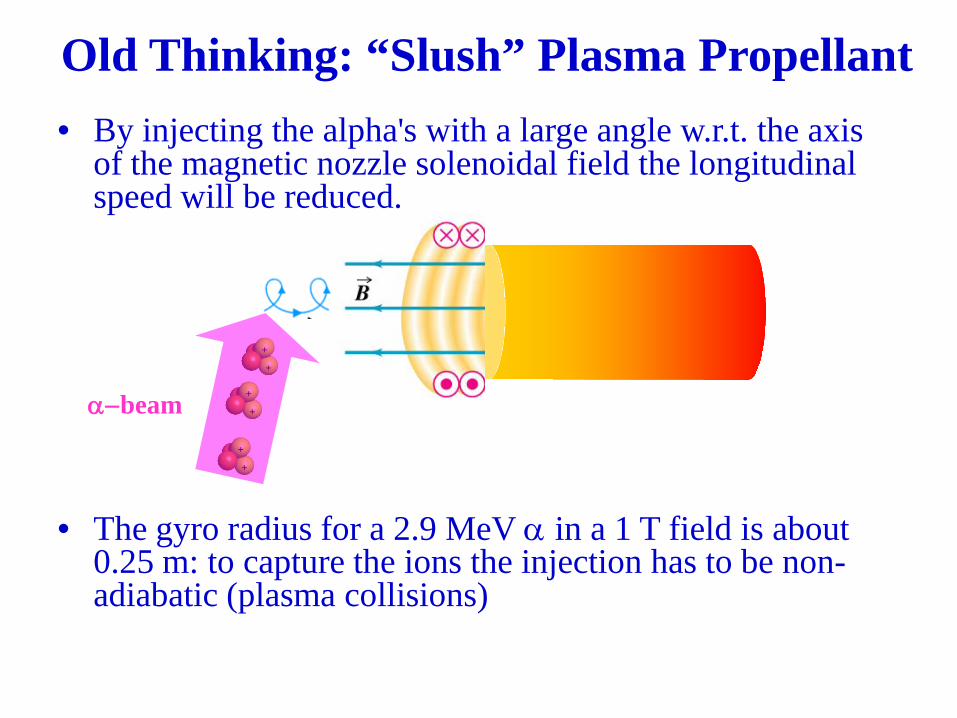
• By injecting the alpha's with a large angle w.r.t. the axis of the magnetic nozzle solenoidal field the longitudinal speed will be reduced.
• The gyro radius for a 2.9 MeV α in a 1 T field is about 0.25 m: to capture the ions the injection has to be non-adiabatic (plasma collisions)
α−beam
Old Thinking: “Slush” Plasma Propellant
The Proposed Approach: Fusion Energy-to-Thrust Direct
Conversion
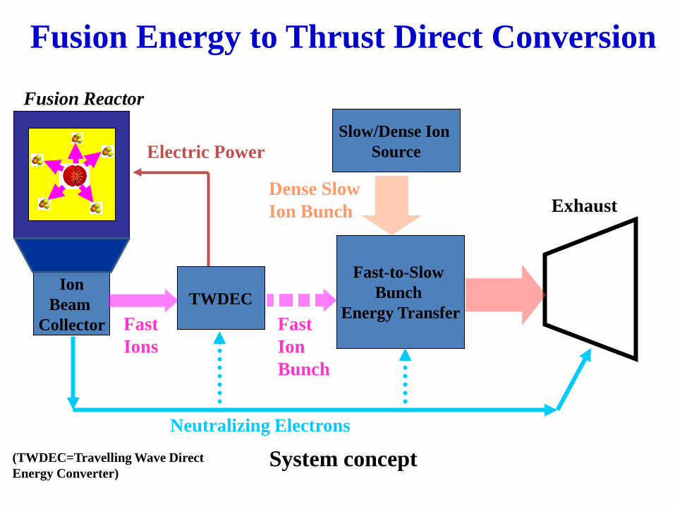
Fusion Energy to Thrust Direct Conversion
TWDEC
Fusion Reactor
Electric Power
Fast Ion Bunch
Exhaust
Ion Beam
Collector
Slow/Dense Ion Source
Fast-to-Slow Bunch
Energy Transfer Fast Ions
Dense Slow Ion Bunch
Neutralizing Electrons
System concept (TWDEC=Travelling Wave Direct Energy Converter)

Converting Beam Energy into Thrust
Two basic processes operate concurrently: 1. Fast-to-Slow Bunch electrostatic energy exchange
2. Magnetic Piston effect created by fast beam bunches confined into a spiral trajectory
Electric Field
Slow, Dense Bunch Speeds Up Fast Ion Bunch
Slows Down
j
vbunch
Slow, Dense Bunch Speeds Up
Fast Ion Bunch Slows Down
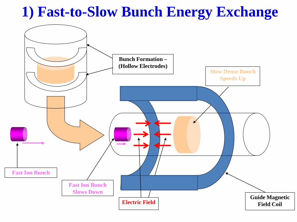
1) Fast-to-Slow Bunch Energy Exchange
Electric Field
Bunch Formation – (Hollow Electrodes)
Slow Dense Bunch Speeds Up
Fast Ion Bunch Slows Down
Guide Magnetic Field Coil
Fast Ion Bunch

Fast-Electron, Neutralized Beam Scenario
Slow Dense Bunch Speeds Up
Fast-Electrons (neutralizing, not
recombining)
Fast-electron beam (possibly partially neutralizing) may allow higher densities

“Magnetic Piston”: an Old Concept
Concept illustration (from W.B. Kunkel, “Plasma Physics in Theory and Applications”, 1966)
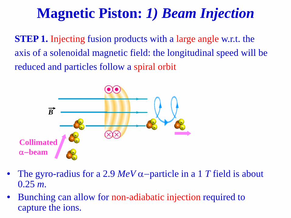
Collimated α−beam
Magnetic Piston: 1) Beam Injection
B
• The gyro-radius for a 2.9 MeV α−particle in a 1 T field is about 0.25 m.
• Bunching can allow for non-adiabatic injection required to capture the ions.
STEP 1. Injecting fusion products with a large angle w.r.t. the
axis of a solenoidal magnetic field: the longitudinal speed will be
reduced and particles follow a spiral orbit
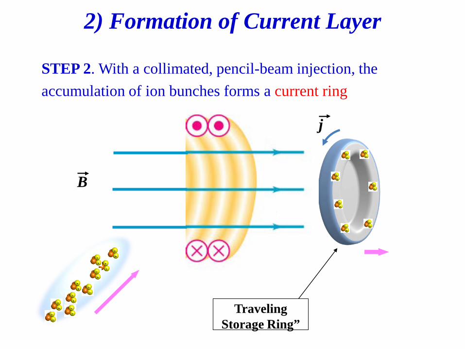
STEP 2. With a collimated, pencil-beam injection, the
accumulation of ion bunches forms a current ring
2) Formation of Current Layer
j
Traveling Storage Ring”
B

STEP 3. As more particles are collected the current in the
layer increases that, in turn, increases the magnetic field
3) Magnetic Field Increase
j
j
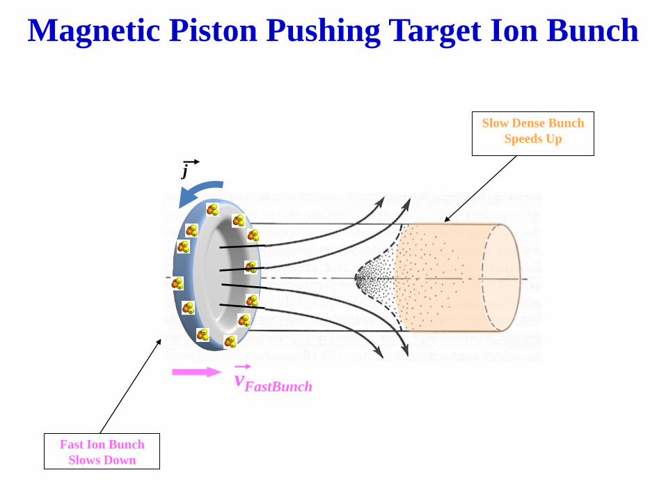
Magnetic Piston Pushing Target Ion Bunch
Slow Dense Bunch Speeds Up
vFastBunch
Fast Ion Bunch Slows Down
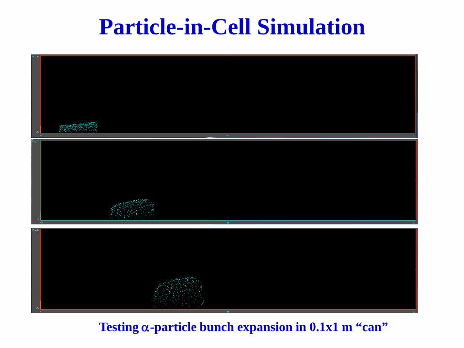
Particle-in-Cell Simulation
Testing α-particle bunch expansion in 0.1x1 m “can”

Near-Term Experimental Plans
• University of Illinois Urbana-Champaign (UIUC) Fusion Studies Lab: experimental campaign on key physics issues: – Utilization of the Helicon Injected Inertial Plasma
Electrostatic Rocket (HIIPER) plasma jet for the generation of a high-density ion “bunched” beam
– Validating the direct energy-to-thrust conversion via fast-slow bunch interaction
– Testing of the TWDEC at higher density: TWDEC stage directly connected to a IEC plasma device.
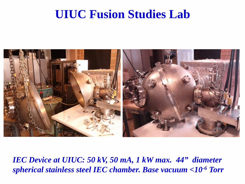
UIUC Fusion Studies Lab
IEC Device at UIUC: 50 kV, 50 mA, 1 kW max. 44” diameter spherical stainless steel IEC chamber. Base vacuum <10-6 Torr

IEC Device at UIUC: plasma from a 2.2 kW Helicon source
UIUC Fusion Studies Lab
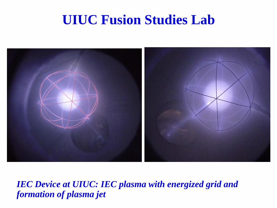
IEC Device at UIUC: IEC plasma with energized grid and formation of plasma jet
UIUC Fusion Studies Lab

Research Plan F.Y. 2011-2012
1st Quarter Physics process definition at the system-level and evaluation of overall performances.
2nd Quarter Particle-in-Cell computer modeling and simulation of subcomponents
3rd Quarter System-level modeling refinement, in-depth simulation and testing of overall performances and key physics issues
4th Quarter Revised detailed design. Final recommendation for next-step developments.