anders ekberg - chalmers
TRANSCRIPT
WEAR Ð SOME NOTES
Anders [email protected]
Dep. of Solid Mechanics, Chalmers Univesity of Technology1997-08-05
INTRODUCTION AND PURPOSEThis report is part of the graduate course CONTACT MECHANICS AND WEAR.This is a “literature course” during summer of -97. The contents of the courseshould be equivalent to 6 weeks of full time work.
Note that the comments reflect my thoughts on the paper. I may wellhave misunderstood some of the contents etc. Also, I have included myown associations and comments in the notes below (not always explicitlystated). So, read the following with a “suspicious mind”.
This paper is produced using FrameMaker™ 5.1.1 on a PowerMac™. The file has then been saved as a postscript™-file and moved toa HP-workstation using Fetch™3.03. Finally, it has been converted to a pdf-file using Adobe Distiller™ 3.0. The document uses thefonts New Century Schoolbook, Times and Symbol.
This paper mainly consists of notes from [1]
1. SURFACE DAMAGESurface damage occurs in the surface layers, where structure and compositionoften are very different from those of the virgin material.
1
2
(22)
Surface damage can involve
NO EXCHANGE OF MATERIAL
❏ Structural changes❏ Plastic deformation❏ Surface cracking
LOSS OF MATERIAL
❏ Wear
GAIN OF MATERIAL
❏ Pickup of loose particles❏ Corrosion
Disadvantageous results of surface damage can be that
❏ Material losses eventually consume the wear part❏ Material losses deteriorate the function❏ Disadvantageous topography, structure, composition etc. deterio-
rates the function❏ Wear particles deteriorate the function
But the surface damage can also be beneficial to the function (e.g. run-in ofmechanical parts).
As for wear, there are several rival mechanisms that contribute. For steadystate wear, the relative amount by which a mechanism contributes to totalwear (volume) is approximately proportional to the area fraction occupied bythe scars of that mechanism.
1.1. SURFACE CRACKING
Two ways that tensile stresses, needed to propagate surface cracks, can begenerated in tribological contact are
❏ Heat expansion of the surface layer beyond the compressive yield lim-it followed by cooling. This often leads to cracking in a network pat-tern.
❏ Friction forces that generate tensile stresses at the trailing end of thecontact. Surface cracks caused by friction forces usually result in apattern of parallel cracks perpendicular to the sliding direction.
Surface cracks are less likely to be observed in systems with ductile materials.Also, if the surface layer is subjected to wear rates higher than crackpropagation rates (in absence of wear), cracks are also unlikely to occur.
1.2. WEAR AND EROSION
Definition: Wear; damage to a surface that generally involves progressive loss of material and is due to relative motion between that surface and a contacting substance or substances.
3
(22)
Definition: As I understand, erosion is loss of material resulting from a repeated impact from a stream of particles???
Plastic shear deformation of a surface is one sign of wear. This is typicallyfollowed by shear fraction, which leads to a scale-like topography. Wear canalso be accompanied by a number of other surface damage modes, such asextrusion, chip formation, tearing, brittle fracture, etc.
1.3. SOME STANDARD COUNTER-MEASURES AGAINST SURFACE DAMAGES
DAMAGE CAUSED BY PLASTIC DEFORMATION
❏ Increase the load-bearing area❏ Decrease the load❏ Lubricate❏ Increase the yield stress❏ Cooling (reduces the softening)❏ Surface coating
DAMAGE CAUSED BY BRITTLE SURFACE FRACTURE
❏ Lubricate❏ Promote formation of friction reducing oxide layers❏ Lower normal stresses❏ Increase load bearing area
DAMAGE CAUSED BY SURFACE CRACKS
Study the formation pattern to reveal details of contact situation. Dependingon whether the cracks are formed by high shear stresses or by heating (seeabove), the pertinent measure has to be reduced.
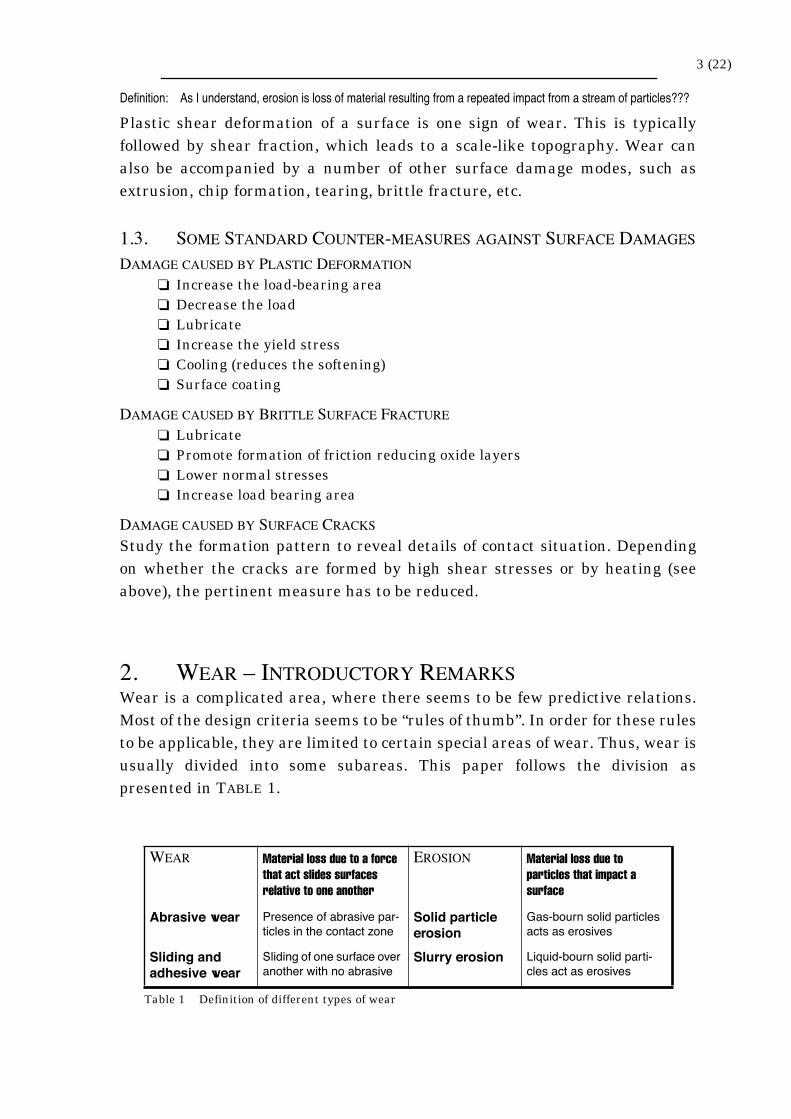
2. WEAR Ð INTRODUCTORY REMARKSWear is a complicated area, where there seems to be few predictive relations.Most of the design criteria seems to be “rules of thumb”. In order for these rulesto be applicable, they are limited to certain special areas of wear. Thus, wear isusually divided into some subareas. This paper follows the division aspresented in TABLE 1.
WEAR Material loss due to a force that act slides surfaces relative to one another
EROSION Material loss due to particles that impact a surface
Abrasive wear Presence of abrasive par-ticles in the contact zone
Solid particle erosion
Gas-bourn solid particles acts as erosives
Sliding and adhesive wear
Sliding of one surface over another with no abrasive
Slurry erosion Liquid-bourn solid parti-cles act as erosives
Table 1 Definition of different types of wear
4 (22)
3. ABRASIVE WEARDefinition: Abrasive wear; due to hard particles or protuberances that are forced against and move along a solid surface.
Loss rates are not inherent to a material (i.e. not a materials property).
Abrasion is typically categorized according to type of contact, as well as contactenvironment. The contact can be two-body contact, where an abrasive slidesalong a surface and three-body contact, where the abrasive is caught betweentwo surfaces. The former case will typically lead to wear loss 10–1000 times asmuch as those of three-body contact (for given load and path length).
Abrasion can also be categorized as low stress, where the abrasive remainsfairly intact; high stress, where the abrasive is crushed; and gouging, where arelative large abrasive will cut the material.
3.1. ABRASIVE MECHANISMS
Several mechanisms have been proposed to explain how the material isremoved from a surface during abrasion. These mechanisms include fracture,fatigue and melting.
Comment: And also plastic ratchetting, see the work of Kapoor.
No single mechanism can, probably, account for all the loss.
Some of the processes involved in the abrasive wear is
❏ Plowing, where material is displaced from a groove to the sides. Doesnot result in any real material loss.
❏ Microfatigue, ???❏ Wedge formation, i.e. the formation of a wedge on the front of an abra-
sive tip. This requires a ratio of the contact interface shear strengthrelative to the bulk shear strength of 0.5 to 1. Fairly mild form ofwear.
❏ Cutting, where a chip is removed. The most severe form of abrasive
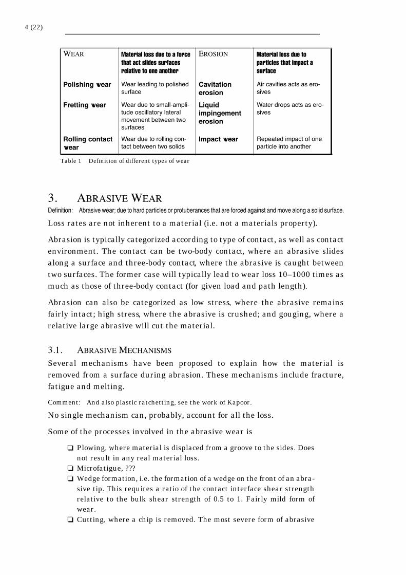
Polishing wear Wear leading to polished surface
Cavitation erosion
Air cavities acts as ero-sives
Fretting wear Wear due to small-ampli-tude oscillatory lateral movement between two surfaces
Liquid impingement erosion
Water drops acts as ero-sives
Rolling contact wear
Wear due to rolling con-tact between two solids
Impact wear Repeated impact of one particle into another
WEAR Material loss due to a force that act slides surfaces relative to one another
EROSION Material loss due to particles that impact a surface
Table 1 Definition of different types of wear
5 (22)
wear. For a sharp abrasive particle, a critical angle (»45° – 85°) dic-tates the transition from plowing to cutting. Also, the degree of pene-tration is critical to this transition (depth of penetration / contact area> 0.2 Þ cutting).
❏ Microcracking, where small cracks are formed du to high (above thefracture toughness limit) stresses close to the abrasive. This type ofwear occur only for brittle materials.
For abrasive wear, the maximum volume of wear that can occur is given by
(1)
where, W is the volume of removed material, A is the cross-sectional area of thegroove and d is the sliding distance. The cross-sectional area of the groove canbe expressed as
(2)
Here, k1 is a shape dependent constant and p is the depth of penetration, which
can be expressed as
(3)
where L is the load and H is the hardness of the material. k2 is a constant whichis influenced by
❏ The plowing / cutting range❏ Rolling of the abrasive❏ Break down of the abrasive❏ ¼
Combining the equations give
(4)
which is known as Archard’s equation. This relation was originally derived foradhesive wear (see CH. 9.), but has proven useful in abrasive wear as well.
Some other wear equations are the empirical equation of Khrushchov
(5)
where E is the elastic modulus.
The Zum Gahr equation reads
(6)
where
W Ad=
A k1p=
p k2LH----=
W k3LdH-------=
Wk5
E1.3
---------=
W fabAvd=
6 (22)
(0 for plowing, 1 for cutting) (7)
and Av is the cross-sectional area of the wear groove, A1 and A2 are the cross-
sectional areas of the material displaced to the side of the groove (left and rightrespectively), and d is the sliding distance.
Comment: Note that load is only implicitly involved in the equations above through the appearance of k5 and Av. These have to be related to the load e.g. through (2) and (3))
The wear resistance, R, is defined as
(8)
3.2. EFFECTS OF MATERIAL PROPERTIES OF ABRASIVE WEAR
There are a variety of material characteristics that have been shown to eitherhave an effect on or correlate with abrasive wear. Some of these properties are
❏ Hardness; linear relationship between hardness (of worn surface)and wear resistance (different slopes for pure materials and alloys).
❏ Elastic modulusComment: Doubtful how this would influence. A high modulus would give high contact
stresses, which would probably decrease the wear resistance. But the elastic modulus is connected to many other properties so ¼
❏ Yield strengthComment: A high yield strength should probably increase the wear due to less fracture. But
the occurrence of strain hardening could complicate the situation ¼
❏ Melting temperatureComment: This should probably increase the wear resistance due to less softening.
❏ Crystal structure; cubic crystals wear at about twice the rate of hex-agonal crystals.
❏ Microstructure; the higher the strain hardening and the ductility, thebetter the wear resistance. A common way to improve wear resistanceis to produce a second phase.
❏ Fracture toughness; a high toughness increases the wear resistance,mainly for brittle materials (figures of proportionality to fourth powerof toughness).
❏ Composition; alloying is often used to increase wear resistance.
There are families of materials that have demonstrated good wear resistance.They are typically hard materials that resist scratching. These materials canalso be used as coatings on other less resistant materials.
For metals to resist abrasive wear, the primary requirement is hardness. Inaddition, addition of carbides, especially large such (in relation to the abrasive),and carbide-forming metals, improve wear resistance.
fab
Av A1 A2+( )Ð
Av-------------------------------------=
R 1W-----=
7 (22)
Question: How does this relate to fatigue properties???
Alloyed white cast irons are the most resistive iron-base alloys due to theformation of carbides during solidification.
3.3. ENVIRONMENTAL EFFECTS
3.3.1. ABRASIVE
Changing the abrasive will change the wear rate. Characteristics of theabrasive that will contribute is
❏ Critical angle (see above). A round abrasive will induce less wear.❏ Hardness of the abrasive. When the hardness of the abrasive exceeds
that of the worn material, wear will become much worse.❏ Toughness of the abrasive. A tough abrasive will induce more wear.❏ Size of the abrasive
Comment: For a given volume of abrasive, larger abrasive should impose less wear, since there are fewer points of contact and the contact stresses at these points are lower.
❏ ¼
3.3.2. TEMPERATURE
One could expect more wear as the temperature increases. However, at least forcopper and aluminum, the effect is very small. This has been contributed to thefact that small areas of contact are heated during abrasion. The metal will flowat these contact points. For high initial temperature, the flow stress will bereduced, which will result in less heating due to abrasion. The result will bethat the points of abrasive contact will have a similar steady state temperatureregardless of initial temperature. Thus, the wear rates will be similar.
3.3.3. SPEED OF CONTACT
The wear rate increases slightly with increased speed in the range 0–2.5 m/s.This may be attributed to a slight increase in frictional heating.
3.3.4. LOAD
Wear is proportional to applied load, see (4), as long as the load levels do notlead to fracture of the abrasive. In this case, the wear rate will decrease if theabrasive is rounded or may increase if the fractured abrasive have sharpcorners.
3.3.5. HUMIDITY
The effect of humidity on wear rates is far from clear. Results are oftencontrary. The influence of humidity is of its ability to influence the surface layer(often consisting of oxides).
3.3.6. CORROSIVE EFFECTS
Abrasive wear is often enhanced by corrosive conditions. A synergism oftenoccurs between corrosion and abrasive wear. The abrasive removes the
8 (22)
(normally) protective surface layers and creates fresh surfaces which rapidlycorrode.
4. POLISHING WEARDefinition: Interaction between two solids that produces a polished surface on at least one of the contacting surfaces by
removing material.
Since “polished” can not be quantitatively defined, the definition is not precise.Also, this has the consequence that polishing wear can be considered as specialcase of other basic wear processes, mainly abrasive wear. However, there arecertain unique mechanisms involved.
Polished wear has mainly been studied for simple systems that are intended toproduce a polished surface. Studies for complex engineering systems are rare.
Polishing wear can only occur for materials of high intrinsic reflectivity, mainlymetals.
4.1. POLISHING WEAR WITH ABRASIVES
This is one of the most common causes of polishing wear and polishing wearwith abrasives is just a special case of abrasive wear, see CH. 3. The question isunder which circumstances abrasive wear systems produce surfaces with a finetopography.
A difficulty of applying concepts of abrasive wear to polishing wear withabrasives is that the former are larger-scale processes. For instance, (micro-)indentation tests are carried out on a much larger scale than the processesoccurring during polishing wear. However, it seems as if the similarityprinciple is valid even for the smallest conceivable indentations.
Comment: Does the similarity principle mean that measured hardnesses for different materials should be comparable. I.e. hardness is a valid materials property even at these small scales???
Still, the comparisons should only be actually valid if the workpiece is fairlyhomogenous over the entire range of specified indentation sizes. Thus, formetals, an inclusion can be small enough not to influence abrasive wear, nutstill large enough to have an effect on the polishing wear behavior.
As for abrasion wear, the mechanical properties of the abrasive and the surfaceare very important. Also, for a polished surface to appear, the applied forcemust be below a limiting value (for example ~0.01 N for a workpiece of hardness1000 HV), since the formed grooves has to be narrow.
9 (22)
4.2. POLISHING WEAR WITHOUT ABRASIVES
Two mechanisms that can induce polishing wear in the absence of an abrasiveare
❏ Surface flow; in which the asperities on a rough surface is flattenedby the compressive force of another, stronger, solid.
❏ Chemical-mechanical mechanisms; where the corrosion-protectivesurface film of a metal surface is removed by a rubbing solid. The filmis then reformed, during which a thin layer of the workpiece is con-sumed. Repetition of this process gradually removes the crests andproduces a smother surface.
5. SOLID PARTICLE EROSIONDefinition: Solid Particle Erosion (SPE) is the loss of material that results from repeated impact of small solid particles.
In this section, only particles entrained in gas are considered. The case ofparticles entrained in liquid is treated in CH. 8., and the case of repeated impactby another solid is treated in the section CH. 12.
The difference between erosion and abrasion is that erosion refers to a series ofparticles striking and rebounding from the surface, while abrasion refers to thesliding of abrasive particles across a surface under the action of an externallyapplied force. Thus, the force that governs erosion is the deceleration of strikingparticles, while in abrasion the force is externally applied and approximatelyconstant.
Solid particle erosion is to be expected whenever hard particles are entrainedin a medium that impings a solid at any significant velocity (greater than 1 m/s).
Manifestations of SPE include
❏ Thinning of components❏ Macroscopic scooping appearance following the gas/particle flow field❏ Surface roughening❏ lack of directional grooving characteristic of abrasion❏ Formation of ripple patterns on metals (not all cases)
5.1. VARIABLES AFFECTING PURE EROSION
In the absence of corrosion, several variables can affect the erosion rate, E. Thisrate is commonly given as volume (or mass) of material removed per unit massof erodent impacted.
The discussion below has its emphasis on metals. Here, one mechanism ofmaterial removal is the deformation of surface material into thin platelets,
10 (22)
which eventually gets detached and forms platelike debris particles. Theseplatelets are often considerably smaller than the average crater dimension. Itseems like this platelet mechanism is the predominant mode for 90° incidenceangle (see below), whereas, at lower incident angles, the predominant mode ismicromachining (as cutting and plowing). However, there is not a generalagreement in literature on this.
Another effect that can be significant is the embedding of erosive particlefragments in the specimen surface.
IMPINGEMENT VARIABLES
❏ Particle velocity: Generally a power dependence of the type is found. Here, k is a constant, v is the velocity and n is an exponentthat depends on material and erosion conditions. Usually 2 £ n £ 2.5for metals.
❏ Angle of incidence, a (between indent particle direction and surface[the reference says particle surface, but this is probably a typing er-ror]): Ductile materials have a maximum erosion rate, E, at 15° < a <30° (typically). Brittle materials have Emax at a»90°.
❏ Flux (particle concentration): Because of inference of rebounding par-ticles with incident particles, the surface becomes shielded at higherfluxes. This leads to an exponential decrease of E with increasingflux.
Comment: Note that E is defined as volume of removed material per unit mass of erosive . Thus, the volume of removed material may increase even if E decreases.
❏ Temperature: This influence is very hard to predict. In some cases Eincreases, while in other it decreases.
❏ Particle rotational speed: Very hard to measure.
Comment: A rotational speed should probably give an increase in erosion rate.
PARTICLE VARIABLES
❏ Particle shape: Angular particles give higher erosion rate thanspheres.
❏ Particle size: The effect is very small as long as the particle size is ³100 mm. For particles smaller than 100 mm, the erosion rate decreasesrapidly. This is probably due to an increase in the flow stress with de-creasing indentation size.
Comment: This would give a greater hardening and thus less wear.
❏ Particle hardness: See material hardness, below.❏ Particle friability (ease of fracture)
MATERIAL VARIABLES
❏ Hardness: Significant improvements of erosion resistance can be ob-tained when the ratio of particle to target hardness is less than 1.However, increasing the hardness by work hardening have essential-ly no effect on E. Probably because the surface reaches saturation
E kvn
=

11 (22)
work hardening during steady-state erosion.Also, for a specified steel (and a specified a), the erosion rate is nearlyindependent of the hardness.
❏ Work hardening behaviorComment: The higher the work hardening rate and saturation value, the better (probably).
❏ Microstructure❏ ¼
5.2. COMBINED EROSION/CORROSION
The following discussion is limited to the behavior of metals under theinfluence of gas-bourn particles.
The field can be divided into the following categories
❏ Pure erosion; as discussed above❏ Corrosion-affected erosion: When the corrosion increases, a thin layer
of corrosives is developed on the workpieces surface. The “dimen-sions” of the induced stress field during impacting particles are great-er than this layer, which leads to deformation of both the corrosivelayer and the surface. The erosion rate increases. The mechanismsbehind this synergy effect are not fully understood. One likely expla-nation is that bare metal is repeatedly exposed to corrosion.
❏ Erosion enhanced corrosion: Is further divided into three stages:I. The rate of growth of the corrosive layer is essentially unaffected bythe erosion.II. The presence of erosion increases this growth rate.III. Erosion-induced spalling of the corrosive layer enters as an addi-tional scale loss mechanism. This leads to a very thin, or absent, cor-rosive layer and very high corrosion rates. Here, the erosion rate canbe very sensitive to the particle loading rate.The mechanisms governing which of the different stages that will bedominant is complicated and depends on the chemical and mechani-cal properties of the corrosive laver etc.
❏ Pure corrosion: This is not treated here.
6. CAVITATION EROSIONDefinition: Cavitation is defined as the repeated nucleation, growth and violent collapse of cavities, or bubbles, in a
liquid.
Cavities in contact or close to a solid surface will collapse asymmetricallyforming a microjet of liquid directed toward the solid. Also, the cavities do notact independently, but collapse in concert. This effect leads to an enhancedeffect such that the pressures produced by these collapses may cause localizeddeformation and/or removal of material from a surface in the vicinity of the
12 (22)
cavities. The collapse of a cavity cluster starts at the outer perimeter andproceeds inwards. Much of the energy produced by the outer cavities istransferred inwards. The intensity of the collapse of the inner cavities will thusbe very high. Also, there will be a significant, localized, temperature increase(up to 5000 K) associated with the collapse.
6.1. VARIABLES AFFECTING CAVITATION EROSION
CAVITY FACTORS
Some of the parameters that affects the erosive effect of a cavity cluster are
❏ Hydrostatic pressure❏ Cavity cluster size❏ Distance of individual cavities from the solid surface❏ Temperature and density of liquid
The erosion rate will be a balancing act between the energy (acting on the solidsurface) released by the cavities and the ability of the material in this surfaceto absorb this energy.
Further, after the initiation, the rate of erosion as a function of continuedexposion is usually non-linear.
MATERIALS FACTORS
There are probably a number of materials factors that will affect the erosionrate of the material. However, due to the dynamic, shocklike nature of theloading, no universal correlation with quasistatic mechanical properties hasbeen found.
CAVITATION EROSION AND CORROSION
Cavitation can also have a variety of effects on corrosion since it can
❏ Remove a protective corrosive layer❏ Increase diffusion rates of reactive dissolved gases into the metal sur-
face❏ Increase rate of removal of corrosion reaction products from the vicin-
ity of the surface (i.e. not only corrosion layers, but also gases result-ing from corrosion processes etc.)
Unfortunately, no general rules exist on have this combination will affecterosion and corrosion rates, see below.
6.2. SOME GENERAL FACTS ON CAVITATION EROSION
❏ No materials are immune to cavitation erosion (as some are to corro-sion)
❏ Metallic materials that exhibit stress-induced phase transformationshave the highest erosion resistance
❏ The combination of erosion and corrosion can be either synergistic or
13 (22)
less harmful than either process acting alone. There are no generalrules for this.
❏ Coating processes offer a great potential both in designing againstcavitation erosion and in repairing eroded surfaces.
7. LIQUID IMPINGEMENT EROSIONDefinition: Progressive loss of material from a solid surface due to continued exposure to impacts by liquid drops or jets.
Liquid impingement erosion can be a practical problem primarily where thetarget body moves at high speeds and collides with liquid drops that are movingmuch slower.
There are many similarities between liquid impingement erosion andcavitation erosion, since both are, in fact, due to small scale liquid/solid impact.On the other hand, there are very few similarities between liquid impingementerosion and solid particle erosion, even though both involve impact of smallbodies. The differences are due to different damage mechanisms, differentimpact variables and different response of material.
Liquid impingement erosion has some similarities to continuous jetimpingement (“jet-cutting”). However, there are differences, since thecontinuous jet produces stagnation pressure, whereas the discrete impacts inliquid impingement erosion produce much higher shockwave pressures.
Almost all research has been made on two major problem areas: “moistureerosion” of low-pressure steam turbine blades operating with wet stream and“rain erosion” of aircraft or missile surfaces and helicopter rotors.
7.1. MECHANISMS OF LIQUID IMPINGEMENT
The impact pressure can be defined as
(9)
where r is the liquid density, C is the shockwave velocity in the liquid and V isthe impact velocity. For practical impact velocities, this can be approximated by
(10)
where C0 is the acoustic velocity of the liquid and k=2 for water.
As an example, water impacting at 500 m/s, gives an impact pressure of about1250 MPa. The stagnation pressure of a continuous jet acting at this speed is
about (rV2/2) is about one tenth of this value.
P rCV=
P rC0V 1 kVC0------+è ø
æ ö=
14 (22)
The real situation is more complicated due to roundness of impacting dropletsand elastic and plastic deformation of the solid surface.
If erosion rate is plotted against time, the following stages can generally beseen
❏ Incubation stage; in which there is little or no material loss. This maynot appear if the impact conditions are severe enough to cause mate-rial loss for a single impact.
❏ Acceleration stage; during which rate increases rapidly to a maxi-mum
❏ Maximum rate stage; where the erosion rate remains (nearly) con-stant
❏ Deceleration (or attenuation) stage; where the erosion rate declinesto (normally) 1/4 to 1/2 of the maximum rate
❏ Terminal (or final steady-state) stage; in which the rate remains con-stant once again indefinitely. However, in some tests, the erosion ratecan continue to decline or fluctuate. Also, for some brittle materials,the rate can increase once again in what is called a “catastrophicstage”
The measures that are normally used to quantify a material is the
❏ Rationalized erosion rate; which is the volume of lost target materialdivided by the volume of liquid impinged
❏ Rationalized incubation period; which is the number of stress pulsesexperienced by a typical point during the incubation period
Some variables that affect the (maximum) erosion rate are
❏ Impact velocity; At low impact velocity, there is a “threshold” inwhich no material loss is observed at normal operating times.
❏ Impact angle; As a first approximation, erosion depends only on thenormal component of the impact velocity. However, once a surface be-comes roughened, the effect of a tangential component should proba-bly become more pronounced
❏ Droplet size; The erosion rate (i.e. erosion due to a given amount ofliquid) decreases with drop size. There is no obvious explanation tothis phenomenon.
❏ Liquid density; Erosion rate shows dependencies of about the 2:nd to2.5th power of liquid density
❏ Acoustic velocity; Although this variable occurs in the theoreticaltreatment, see (10), it is unclear how the practical influence is.
❏ Cyclic deformation properties; good correlation has been found to ero-sion rate.
❏ Hardness; The hardness of the surface has a strong effect of the ero-sion resistance of the material. The harder the material, the smallerthe erosion rate (about 2nd power of the change in Vickers hardnessnumber). However, this does not necessarily apply when different
15 (22)
materials are compared.Comment: This could be due to different brittleness, and thus different failure modes, for
different materials.
There exist empirical formulas to predict incubation times and erosion rates.These formulas predict maximum erosion rates within a factor 3 for most tests.The error for incubation times are greater.
7.2. MEANS OF REDUCING LIQUID IMPINGEMENT EROSION
Some means are
❏ Reduction of impact velocity❏ Modification of surface geometry to decrease normal component of
the velocity (i.e. “tilting” the surface)❏ Reduction of droplet size❏ Reduction of time of operation under most severe conditions❏ Selection of resistant material❏ Application of a shielding layer
8. SLURRY EROSIONDefinition: Wear of a material exposed to a high-velocity stream of slurry (mixture of solid particles in a liquid)
The interest of slurry erosion has increased since the starting of mineraltransportation through pipelines.
Wear response of a material in a certain slurry does not indicate how thismaterial would respond to another slurry. Similarly, the effect of a certainslurry on one material does not indicate how it would affect other materials.
Slurry erosion consists of several wear modes, such as
❏ Abrasion-corrosion wear; which is the result of abrasive rubbing inthe presence of a corrosive liquid
❏ Crushing and grinding; occur in abrasive metal-to-metal contact❏ High velocity erosion; can become very destructive if velocity is above
some 6 to 9 m/s. However, this is unusual.❏ Low-velocity erosion is a low-rate wear mode that occurs there is a
flow of slurry at low velocities. Here, the velocity close to the surfaceis often close to zero and thus, the wear rate is very low.
❏ Saltation wear; is due to sediment transportation where particlesmove forward in a series of short bounces from the bottom surface.
❏ Cavitation; see CH. 6.
16 (22)
9. SLIDING AND ADHESIVE WEARDefinition: Sliding and adhesive wear is wear, where the majority of particle removal is generated by the relative, high-
amplitude, sliding of two surfaces in the absence of abrasives.
Comment: This definition is made by me.
No specific agency can be identified as the cause of wear. Thus, if no abrasivecan be found, if the amplitude of sliding is larger than in fretting and if thematerial loss is not governed by oxidation, etc., adhesive wear is said to occur.
However, adhesion is not the cause of wear, but only a consequence of contact.Wearing occurs when interfaces in contact are made to slide and the locallyadhered regions must separate. This results in a very wide range of wear rate.
9.1. MECHANISMS OF ADHESIVE WEAR
In the sliding area, metals will usually be covered with a film of oxide, which iscovered by a second film of adsorbed gases and oils. The thickness of these filmsare »10 nm. These films intervene in the adhesion (bonding) of substratematerials. Variations in thickness and properties of these films is one reasonfor the wide range of friction data.
When two surfaces slide against each other, there will be some contact betweenthese layers. If the contact pressure is high, a layer may fracture and exposesubstrate material (especially if the bulk material deforms plastically). Smallregions of the two surface materials may then come in contact and bond. Thestrength of these bonds will depend on the materials. Also, the conformity of thecontacting surfaces influences the bonding.
The most widely known equation of adhesive wear is due to Archard, see (4).This equation can also be expressed the rate of wear (i.e. volume removed pertime unit) as
(11)
where ¡ is the wear rate, L is the applied load, V is the sliding distance and His the hardness of the softest material. k is a constant that sometimes is
referred to as the wear coefficient. It ranges from 10-3 for unacceptable wear
rates to £10-7 for practical systems. However, these numbers are just verybroad guidelines for anticipated wear rates.
Adhesive wear actually seems to involve over 25 variables, some of which aredifficult or impossible to measure. Thus, there is no general applicable equationand simulative testing should be performed.
For steels (0.12% C), some observations are
¡ kLVH
--------=
17 (22)
❏ Increasing load may decrease wear rate; presumably by increasingthe contact temperature and thus forming austenite.
❏ Wear debris is a mixture of oxides❏ Increased hardness decreases wear rate since it diminishes the tran-
sition to severe wear.❏ Inert gas broadens this transition region, whereas oxygen narrows it.❏ In the mild wear regime, initial wear becomes high if oxides are
chemically removed.
Comment: Thus, the transition from mild to severe wear seems, mainly to be a question of if the deformation is high enough to crack the oxide layer.
9.2. MEANS OF REDUCING ADHESIVE WEAR
❏ Avoid sliding similar materials (particularly metals) together❏ High hardness is a desired property (if fatigue is not to be expected).
However, hard metal sliding should be avoided in lubricated systemsdue to the risk of scuffing.
❏ Consider the effect of relative hardness of different phases.❏ Lubrication will reduce wear.❏ Lubrication can be applied by providing a corrosive atmosphere,
which will produce surface films.
10. FRETTING WEARDefinition: Fretting is small-amplitude oscillatory movements between contacting surfaces, nominally at rest.
One of the consequences in normal atmospheric conditions is production ofoxide debris, thus the term “fretting wear” or “fretting corrosion”. Fretting wearis closely related to early initiation of fatigue cracks, i.e. “fretting fatigue”.
There are cases where the movement is not simply tangential, but iscomplicated by a normal force that also oscillates to the extent that the surfaceslose contact in each cycle. This leads to a hammering effect, which is termed“impact fatigue” (see CH. 12.). In this case, the phase relationship between thetwo motions can be of importance.
In fretting wear, damage can be caused by movements with amplitudes assmall as »125 nm. However, relative movement between the surfaces has to bepresent in order for fretting wear to occur.
There is an effect of synergy between fretting wear and corrosion (strengthreduction factors of 2–5 and even greater). Fretting also greatly accelerates thecrack initiation process. Thus, in “normal” fatigue, crack initiation may accountfor 90% of fatigue life, whereas in fretting fatigue, initiation could occur in £5%of the fatigue life.
Comment: This should be very dependent on the loading conditions. Also, one could turn the

18 (22)
argument around and state that small cracks propagate very slowly under fretting conditions, presumably due to the influence of compressive loading.
10.1. LOAD PARAMETERS AFFECTING FRETTING WEAR
❏ Amplitude of slip: A relative movement is essential (see above). Thewear rate relationships are “sigmosoidal” with constant wear ratesfor amplitudes >100mm (i.e. for a specific sliding distance). Thissmall-amplitude characteristic of fretting is an important feature ofthe process. Relative velocities of the two surfaces will thus be muchlower, even at high frequencies, compared to unidirectional sliding.
❏ Normal load: In contact between conformal surfaces, plastic deforma-tion is to be expected at contacting high points. The actual area of con-tact is thus directly proportional to the applied load. Because frettingoccurs only at these high points, it follows that the amount of wearshould be proportional to the applied load. This is generally found tobe the case.
❏ Frequency: There is an increase in wear volume at low frequency fora given number of cycles.
❏ Type of contact: The ease with which debris can escape from the con-tact region is of importance (it can also give rise to other problems dueto contamination of other machine parts). If debris is allowed to es-cape, this will lead to more frequent metal-to-metal contact and high-er wear rates. See also below.
❏ Type of vibration: In subresonant loading, the damage is said to be“typical fretting damage”. In resonant conditions, the wear rates willbe much lesser due to the lower dissipation of energy. In superreso-nant conditions, there will be a tearing of the surface due to 90° phaseshift between the tangential and normal vibrations.
❏ Impact fretting: The combination of impact and fretting is, for somecases, more severe than fretting alone. In other cases, there is littleinfluence and continous contact is more damaging. An importantvariable is the phase relation between normal and tangential vibra-tions.
❏ Surface finish: The more highly polished the contacting surfaces, theworse the damage. Shot peening can be used to produce a rough sur-face and also work hardening and residual compressive stresses inthe surface. In experiments, a shot-peened surface with very low fret-ting wear rate experienced wear rates similar to unpeened steels af-ter polishing.
Comment: Polishing could influence the residual stress field if surface temperatures are raised high enough. This could perhaps account for some of the effect.
❏ Residual stresses: This should be a parameter of high importance iffatigue is a damage mechanism in fretting wear. However, the fret-ting process itself can produce residual stresses. Experimental re-sults show that the depth of the wear scar increased with tensile- anddecreased with compressive residual stresses. Also, the presence of a
19 (22)
static tensile stress can lead to propagation of fretting inducedcracks.
10.2. MATERIAL AND ENVIRONMENTAL PARAMETERS AFFECTING FRETTING WEAR
In some investigation, a formation of a white, etch-resistant layer has beendetected in fretting of carbon steels. This material is extremely hard and tendsto develop cracks. It is often referred to as martensite.
Comment: This phenomenon occurs in railway wheel/rail application.
As expected, metals that rely on a protective oxide film can suffer considerablefretting damage.
For different materials in the interface, their mutual solubility is an importantparameter. High solubility leads to high damage.
As for debris, the accumulation of debris between the accumulation betweensurfaces tend to reduce wear. Abrasion by the oxide debris gives no significantcontribution.
In vacuum, little wear takes place. However, there are considerable surfacedamage due to adhesive transfer of material. This effect ceases for pressuresabove » 0.1 Pa.
Most metals (including iron) shows a peak coefficient of friction at values ofrelative humidity between 10% and 15%. This gives a corresponding peak inwear.
For very low temperatures (4 K), steel show little wear, but high friction,similar to the case of vacuum. At 77 K, the wear rates were similar as for 293K. For temperatures of 500°, there is a great reduction in friction and wear.This is for oxidizing atmospheres, where many alloys develops a very smoothoxide surface (“glaze” oxide). In argon, however, surface damage is severe atthis temperatures.
10.3. MECHANISMS OF FRETTING WEAR
The progress in time for fretting wear (under conditions where escape of debrisis not easy) is:
❏ Initial stage; of a few thousand cycles. Here metal-to-metal contact isprevalent, resulting in local welding, roughening of the surface andhigh friction. Fatigue cracks, if initiated, are initiated in this stage.
❏ Formation of debris beds; with a corresponding fall in coefficient offriction.
❏ Onset of a steady state; in which friction is more or less constant.
20 (22)
Fretting can be prevented by
❏ Improved design; in which relative movements between surfaces areprevented
❏ Surface treatment; in which the surface is made rougher❏ Coatings; in which a hard coating is applied. Caution is to be observed
since the coatings, if brittle, may crack under plastic deformations ofthe bulk material and act as an abrasive.
❏ Inserts; which will separate the two surfaces.❏ Lubricants; which will smoothen the contact. However, it is often dif-
ficult to maintain the lubricants in the area of contact.
11. ROLLING CONTACT WEARDefinition: Rolling contact wear (RCW) results from the repeated mechanical stressing of the surface of a body rolling
on another body.
Because rolling contact wear (RCW) is generally produced by mechanicalstressing of the affected surface(s), it is often associated with or even referredto as rolling contact fatigue (RCF). As a distinction, one can define that in RCF,fatigue is the damage accumulation process that eventually results in wearparticle formation. Further, the pits of RCW may act as nucleation sites foradditional fatigue cracks. As a result, RCF and RCW are very closely related.
Rolling contact wear is often difficult to detect in its early stages. The precursorflaws may be hidden from view as they grow beneath the contact surface.
In many types of rolling contact arrangements, lubrication is important tominimize the deleterious effects of slip.
11.1. RCW OF DIFFERENT SYSTEMS
GEARS
❏ The wear modes usually involves both rolling and slip or sliding.❏ The design against RCW includes❏ Stress limitations❏ Material choices❏ Adequate form and finish❏ Adequate lubricants and lubrication systems❏ Rust and contaminant protection❏ Elastohydrodynamic considerations
ROLLING-ELEMENT BEARINGS
Pitting, smearing and spalling are important RCW manifestations.
The depth of the spall tends to be related to the location of the maximumHertzian shear stress below the surface.
21 (22)
The fatigue spalling life can be expressed as
(12)
where P is the equivalent dynamic load, C is the load capacity and p is anexponent that depends on the type of loading. For ball bearings, p=3; for rollerbearings p=10/3.
The situation can be complicated by complex combinations of different loading.
11.2. MECHANISMS OF RCWMechanisms of RCW can involve subsurface fatigue, where intersectingsubsurface fatigue cracks form surface pits in rolling elements. It can alsoinvolve mild abrasion from lubricant contamination, it can be affected by wateror acids in lubricants, etc.
Initially, the material may be stressed beyond its elastic limit, causing someplastic deformation. As repeated rolling occurs, elastic shakedown, when nofurther plastic deformation occurs, can set in.
The processes of RCF and RCW generally involves the following steps:
❏ Accumulation of dislocations caused by repetitive stressing of thesubsurface microstructure.
❏ Nucleation of voids or microcracks in regions of maximum Hertzianstress or close to discontinuities, pores or inclusions.
❏ Propagation of microcracks in the subsurface.❏ Linking of the cracks and propagation of the crack tip toward a free
surface.❏ Creation of flakes, pits and/or spalls.❏ Spread of the damage to adjoining parts of the surface.❏ Initiation of major fatigue cracks from surface or subsurface defects
sometimes causing catastrophic failure.
Comment: From the 5th point, the influence of lubricants “exploding” the crack may be of importance. (In the article, it says from the 3rd point, but this is probably a printing error since the crack hasn’t reached the surface by then).
Composite materials may be interesting since they contain internal “crackstoppers” or crack branching interfaces (which will dissipate energy).
Wear particles may give rise to additional damage as they contaminate thecontact.
Improved wear life can be produced by lubrication with adequate load-bearingcapacity.
LCP----è ø
æ öp
=
22 (22)
Increased (fracture) toughness of the solid material increases the wear lifesince it enhances the crack propagation resistance.
Reduction of porosity and inclusion content of the solid material will increasethe wear life since it decreases crack initiation.
12. IMPACT WEARDefinition: Impact wear can be defined as wear of a solid surface due to repetitive exposure to dynamic contact by
another solid body.
The wear mechanisms are, among other, dependent on
❏ Materials used: For example, in polymers, thermal wear can occur.❏ Contact stress range: Compare with contact fatigue vs. fretting fa-
tigue.❏ Impact speed: Increased speed can result in a transition from low-
stressed fretting wear to severe adhesive wear.❏ Loading modes: The relative size of sliding vs. normal impacting
speed components.
From theoretical studies of impact dynamics and experimental studies of wearof different materials, semi-empirical impact wear theories have been derived.
REFERENCES1. ASM International, ASM Handbook, vol. XXX, xxx pp., Materials Park, Ohio,
U.S., 19XX