and - static-pt.com
TRANSCRIPT
Technical Manual
and Replacement Parts List
Manufactured especially for Dunkin Donuts
1600 Xenium Lane North, Minneapolis, MN 55441-3787 Phone (763) 923-2441 Fax(763)553-1209 www.silverking.com
FORM NO. 43881 REV A 3/2017
MODEL: SKECD12-V3
1 Specifications Subject to Change Without Notice.

Table of Contents
Limited Warranty ........................................................................................................................... 3 Two (2) Year Parts Warranty .................................................................................................................. 3
Five (5) Year Compressor Warranty ......................................................................................................... 3
Two (2) Year Labor Warranty ................................................................................................................. 3
Introduction .................................................................................................................................. 5 Unpacking and Setup ..................................................................................................................... 5
Inspecting for Shipping Damage .............................................................................................................. 5
Unpacking the Unit ................................................................................................................................ 5
Location ............................................................................................................................................... 5
Electrical Connections ............................................................................................................................ 5
Safety .......................................................................................................................................... 6 Installation ................................................................................................................................... 6 Operation ..................................................................................................................................... 8
Before the First Use ............................................................................................................................... 8
Initial Startup ........................................................................................................................................ 8
Display Panel ........................................................................................................................................ 8
Threshold Levels ................................................................................................................................... 8 Loading the Unit .................................................................................................................................... 9
Operating the Unit ................................................................................................................................. 9
Refilling the Product Tanks .................................................................................................................... 10
Observing the Current Temperature Inside the Unit .................................................................................. 10
Changing the Temperature Set Point ...................................................................................................... 10
Changing Coolatta Base ........................................................................................................................ 11
Changing the Dispenser Language .......................................................................................................... 11
Cleaning and Maintenance ........................................................................................................... 11 Recommended Cleaning Schedule ................................................................................................. 11
Drip Tray Cleaning and Daily Wipe Down ................................................................................................ 12
Cleaning the Product Tanks ................................................................................................................... 12
Refrigerated Product Compartment Cleaning ........................................................................................... 13
Cleaning Exterior Of Unit ....................................................................................................................... 14
Daily calibration - Adjusting Shot Size ..................................................................................................... 14
Shot Size Targets ........................................................................................................................ 15 Troubleshooting Guide ................................................................................................................. 16 Ordering Parts/Service ........................................................................................................ 17,18,19
2
Limited Warranty Silver King, Inc. warrants to the original purchaser of Silver King refrigerated equipment that the equipment shall be free from defects in material and workmanship under normal use and service as outlined in the Technical Manual. This limited warranty shall apply for a period of two (2) years from the date of original purchase. The Compressor will carry an additional three (3) year warranty. All warranties are subject to specific limitations outlined below.
This limited warranty does not apply to repair or replacement required as a result of carelessness, neglect and/or abuse, including improper installation, incorrect voltage supply, tampering with or altering components and/or equipment or failure to perform proper maintenance. Equipment damaged in transit, by fire, flood or an act of God is not covered. This limited warranty does not include freight, handling, installation, labor (following the two (2) year labor warranty period) or other incidental or consequential costs including product and/or economic loss. This limited warranty is in lieu of all other warranties, express or implied, including those of merchantability, and is non-transferable.
Specific provisions of this limited warranty are as follows:
Two (2) Year Parts Warranty Silver King, Inc. warrants to the original purchaser of new Silver King equipment that such equipment and all parts thereof will be free of defects in material and workmanship, under normal use and service, for a period of two (2) years from the date of original purchase or two (2) years and six (6) months from the date of shipment from the factory, whichever comes first, subject to all terms and conditions herein.
This warranty is limited to repairing or replacing any parts that, at Silver King's discretion, are deemed to be defective within the time period covered by this warranty. The two year parts warranty covers reasonable freight and handling charges. It does not cover special handling charges or expedited means for transport. Use of nonOEM parts may, at Silver King's discretion, void this warranty. If approved, warranty credit for non-OEM parts will be issued at the OEM cost.
Replacement parts sold separately are warranted for 90-days from date of purchase.
Wear items not included: product containers and lids (p/n 37068, 37069, & 37070), drip tray (p/n 37281) and cup guides (p/n 37436) are considered wear items and are not included under the warranty.
Five (5) Year Compressor Warranty Silver King, Inc warrants to the original purchaser for a period of five (5) years from the date of original purchase or five (5) years and six (6) months from the date of shipment from the factory, whichever comes first, that it will replace the compressor with one of similar design and capacity, exclusive of delivery and installation charges, if it is found to Silver King's satisfaction to be inefficient or inoperative due to defects in material or factory workmanship. It is the owner's responsibility to return the serial plate of the defective compressor, or at Silver King's option the complete compressor, to the factory. Failure to do so will void the warranty.
Two (2) Year Labor Warranty Silver King warrants to the original purchaser for a period of two (2) years from the date of purchase or two (2) years and six (6) months from the date of shipment from the factory, whichever comes first, a limited service labor warranty on Silver King refrigerated equipment subject to the following terms;
A factory issued Service Authorization Number must be obtained prior to work being performed under the labor warranty. Call your supplier or Silver King. Claims submitted without a Service Authorization Number will be paid at Silver King's discretion.
3

The labor warranty includes standard straight time labor charges in accordance with Silver King's Labor Warranty Guidelines and reasonable travel time, as determined by Silver King.
The warranty does not cover original installation, startup, normal adjustments or maintenance. Normal adjustments and maintenance include, but are not limited to; temperature control adjustments, temperature indicator calibrations, coil and filter cleaning, condensate drain cleaning.
A second service call for a related failure is not covered.
Use of refrigerants other than specified on the equipment serial plate voids the warranty.
All claims must include; model and serial number of equipment, date of purchase, date of failure, and a copy of the service invoice detailing the defect and service performed. No claim will be processed without this information. All claims must be filed within 60 days from date of service.
4
Introduction The 3 product Dairy Dispenser is designed to house, refrigerate and dispense three dairy products such as 2%, whole, or skim milk, and/or cream. The unit has been set to maintain product within a temperature range of 33 tO 40 Of,
The Dairy Dispenser consists of a refrigerated compartment containing three removable containers for the dairy products, three solenoid-actuated pinch valves that control gravity-induced flow through plastic discharge tubes and an operator interface that allows simple selection of amounts of selected product. The unit also contains a weight measuring sensor to ensure proper product volume dispense regardless of the amount of product in the container. There is no need to manually calibrate the unit when product levels vary.
Unpacking and Setup
Inspecting for Shipping Damage Examine the shipping container immediately upon receipt. Any damage to the container or equipment due to shipping should be reported to the transportation company immediately. Claims should be filed within twenty-four (24) hours. Shipping damage is not the responsibility of Silver King.
Unpacking the Unit This unit is shipped in a corrugated box for protection. When multiple units are shipped to a single location, the unit are boxed and then placed on a skid. The skid is shrink-wrapped to attach the boxes to the skid.
carefully remove the unit from the shipping box. Be sure to follow any orientation or caution labels on the box.
Location When locating this unit, convenience and accessibility are important considerations, but the following factors must be observed:
1. Proximity to a 3-prong 115VAC receptacle for grounding
2. No clearance is required on the sides or back of the unit. The unit must be operated with the legs in place and the top of the unit must be clear of obstruction.
The unit may be located in the drive-through area, on the front counter or in the drink area, whichever is more convenient.
Electrical Connections Prior to connecting the unit to power, be sure to check the data plate, located on the inside of the cabinet, for required voltage. The specifications on the data plate supersede any information contained in this manual.
The standard unit is equipped with a seven (7) foot power cord extending from the bottom of the unit. The unit requires a 115 Volt, 60 Cycle, 1 Phase properly grounded electrical receptacle protected with a 15 or 20 ampere fuse or breaker. The power cord comes with a 3 prong plug for grounding purposes. Any attempt to cut off the grounding spike or to connect to an ungrounded adapter plug will void the warranty, terminate the manufacturer's responsibility and could result in serious injury.
5

Safety
FOR HYDROCARBON UNITS ONLY (R290)
Danger - Risk of fire or explosion. Flammable refrigerant used. To be repaired only by trained service personnel. Do not puncture refrigeration tubing.
Danger - Risk of fire or explosion. Flammable refrigerant used. Do not use mechanical devices to defrost refrigerator/freezer. Do not puncture refrigeration tubing.
Caution - Risk of fire or explosion. Flammable refrigerant used. Consult repair manual/owner's guide before attempting to service this product. All safety precautions must be followed.
Caution - Risk of fire or explosion. To be repaired only by trained service personnel. Use only Silver King approved replacement parts. Flammable refrigerant used.
Caution - Risk of fire or explosion. Dispose of properly in accordance with federal or local regulations. Flammable refrigerant used.
A CAUTION: Risk of Electric Shock • Always unplug the power cord before servicing the unit to avoid electric shock. • Unit MUST be plugged into a 3 prong plug for grounding. Cutting off the grounding spike on the power
cord could result in electric shock to the operator during operation.
• Unit must be plugged into a 15 or 20 ampere fuse or breaker protected circuit. Use of a larger fuse or breaker could result in damage to the unit and electric shock to the operator.
A Moving and/or Hot Parts • Some parts may remain hot even after being unplugged. Always use caution when servicing.
A Possible Back Injury • Assistance should be utilized when moving this piece of equipment.
• Be sure to lift with your legs and not your back when lifting this unit.
Installation
A CAUTION: To avoid injury, the following steps should be performed by two people. Remove the unit from its packaging material and place it near the mounting location and install the four legs underneath the unit. The unit should be oriented such that the power cord reaches the intended power outlet. Remove the plastic protective film from the stainless steel surfaces and wipe all the surfaces with a mild soap water solution.
In order for the unit to function properly, it is important that the unit be level front to back and from side to side. Once the machine is in place and has been leveled, install the display cable and hand tighten the threaded connectors. See Figure 1.
6

Figure 1. Display Cable
Next, install the drip tray and the cup guide. Hand the drip tray on the bottom two screws on the front apron of the unit. See Figure 2. Slide the cup guide into position and secure it on the upper two screws, as shown in Figure 2
Then plug in the power cord on the bottom of the unit, at the right rear, as shown in Figure 3. Run the cord along the rear of the shelf and plug it into the designated outlet.
Cup Guide Mount
Figure 2. Drip Tray and Cup Guide
7
Cup Guide Mount

Operation
Before the First Use
Figure 3. AC Power Cord Connection
Daily calibration Procedure must be performed before the unit is put into operation. See Page 14 (Daily Calibration - Adjusting Shot Size) for details.
Initial Startup This unit operates at ambient temperatures between 32° F (0° C) and 78° F (26°C).
After completing the installation requirements, the unit is ready to start. Turn on the power switch (left side of unit near the front). The display panel should light up and the fan should turn on in the back of the unit. Allow the unit to run for approximately one hour before loading it with product. The internal temperature should be between 33° F and 40° F.
Display Panel The display panel, shown in
Figure 4, contains an LCD display along with the controls for dispensing product. Note: when the unit is first powered up, the LED' S above the Milk, Cream and Skim buttons are flashing. This is to indicate that the containers are either low or empty and need to be filled.
Threshold Levels The Milk and Skimmed Milk levels are set to 600gm and the Cream level to 850gm. The unit goes into lockout when the product in the tanks is less than or equal to these amounts.
Figure 4. Display Panel
Controls The bottom portion of the Display Panel is used to control the dispensing of products. Descriptions of these controls are:
• Drink Size - The top row of buttons is used to identify what size drink is being dispensed.
• Drink Type - The middle row of buttons is used to select what type of drink is being dispensed.
• Product -The bottom row of buttons is used to choose which product is to be dispensed.
8
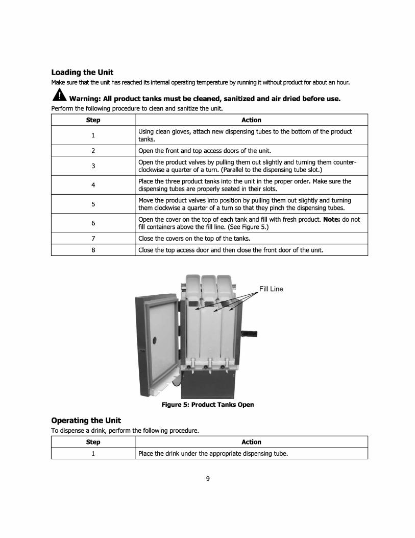
Loading the Unit Make sure that the unit has readied its internal operating temperature by running it without product for about an hour.
A Warning: All product tanks must be cleaned, sanitized and air dried before use. Perform the following procedure to clean and sanitize the unit.
Step Action
1 Using clean gloves, attach new dispensing tubes to the bottom of the product tanks.
2 Open the front and top access doors of the unit.
3 Open the product valves by pulling them out slightly and turning them counter-clockwise a quarter of a turn. (Parallel to the dispensing tube slot.)
4 Place the three product tanks into the unit in the proper order. Make sure the dispensing tubes are properly seated in their slots.
5 Move the product valves into position by pulling them out slightly and turning them clockwise a quarter of a turn so that they pinch the dispensing tubes.
6 Open the cover on the top of each tank and fill with fresh product. Note: do not fill containers above the fill line. (See Figure 5.)
7 Close the covers on the top of the tanks.
8 Close the top access door and then close the front door of the unit.
Fill Line
Figure 5: Product Tanks Open
Operating the Unit To dispense a drink, perform the following procedure.
Step Action
1 Place the drink under the appropriate dispensing tube.
9

2 Select the type of product required for the drink, (bottom row), then go to Step 3 or Step 4, depending on the type of drink required.
If no product is specified, Cream will be dispensed. This default can be changed in the Manager menu
3 For coffee, press the proper drink size button (top row) to dispense the proper amount of product.
4 For Latte, Cappuccino or Coolatta, press the appropriate button (middle row), then press the proper size button (top row) to dispense the drink.
Refilling the Product Tanks To refill the product tanks while in the unit, perform the following procedure.
Step Action
1 Open the front and top access door of the unit.
2 Open the lid of the product tank to be refilled.
3 Refill the tank with the appropriate product for that tank. NOTE: Do not fill containers above fill line. (See Figure 5.)
4 Close the tank lid.
5 Close the top access and front access doors of the unit.
6 The unit is now ready to resume normal operation.
Observing the Current Temperature Inside the Unit To see the current temperature inside the unit, press the up or down arrow until the Temperature is displayed.
Changing the Temperature Set Point If Product temperature is not within spec (33 - 40 degrees) perform the following procedure to adjust cabinet temperature accordingly. The unit follows a 1: 1 ratio. For example, if product temp is 32 degrees (1 degree below product temp spec) adjust the Temp Set Point UP by one degree.
Step Action
1 On the indicator panel, press the up or down arrow until the Config Mode Entr Btn Combo is displayed.
2 Press the X Size button (this is the button combo)
3 Press the Up or Down arrow until the term 'Temp Set Point" is displayed.
4 Press the Select button.
5 Press the Up or Down arrow again to choose the desired temperature (between 35 and 40°).
6 Press the Select button.
7 Press the Home button to return to the main menu.
10

Changing Coolatta Base The Coolatta drink base comes in two types, coffee and neutral. To set the unit for the type used, perform the following procedure.
Step Action
1 On the indicator panel, press the up or down arrow until the Config Mode Entr Btn Combo is displayed.
2 Press the X Size button (this is the button combo).
3 Press the Up or Down arrow until the term "Base Selection" is displayed.
4 Press the Select button.
5 Press the Up or Down arrow again to choose either the Coffee or Neutral selection.
6 Press the Select button.
7 Press the Home button to return to the main menu.
Changing the Dispenser Language Multiple languages will be available in the future for this unit. At that time a procedure will be added to allow the operator to change the language on the unit.
Cleaning and Maintenance Because this unit is intended for use with dairy products, it must be cleaned and sanitized prior to the first use, and every 72 hours during regular use. The unit goes into a cleaning lockout every 72 hours and will stay locked until the containers have been removed for cleaning.
The following items are recommended for sanitary operation of the unit.
• Immediately cleanup all product spilled during the filling process or during drink preparation.
• At various times throughout the day, wipe down the valve assembly with a towel moistened with sanitizer solution an empty and clean the drip tray.
• Empty, clean and sanitize the entire unit every 72 hours.
• New product dispensing tubes MUST be installed each time a tank is cleaned and reloaded.
Recommended Cleaning Schedule The following table is a recommended cleaning schedule for the unit. Follow local schedules, if applicable.
Dispenser Assemblies Frequency
Drip Tray Daily
Valve Area Daily
Dispensing Valves Every 72 hours or as needed
Exterior Weekly
Product Tank Whenever tank is removed and refilled or every 72 hours.
Product Tank Compartment Whenever tank is removed and refilled or every 72 hours.
11
Condenser Every six months (remove back panel and clean dust and debris out of condenser coil).
A Warning: This unit MUST be deaned on a daily basis to ensure sanitary operation.
Drip Tray Cleaning and Daily Wipe Down To clean the drip tray, perform the following procedure.
Step Action
1 Remove the drip tray by lifting it up and off of the two mounting screws.
2 Rinse the drip tray in lukewarm potable water.
3 Place the tray in hot water at a minimum water temperature of 140°F or 60°C. A good quality general-purpose soap should be added to the hot water at the concentrations recommended by the detergent supplier.
4 Wash the tray thoroughly using a bottlebrush to reach all corners and crevices. If a dishwasher is available, this step may be carried out by placing the tray in the dishwasher and washing on the pot cycle.
5 After washing, rinse the tray thoroughly with lukewarm potable water.
6 Turn the tray upside down and let it air dry.
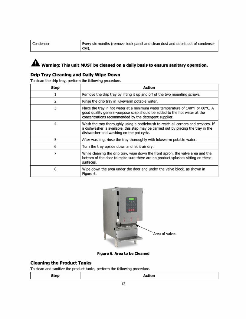
7 While cleaning the drip tray, wipe down the front apron, the valve area and the bottom of the door to make sure there are no product splashes sitting on these surfaces.
8 Wipe down the area under the door and under the valve block, as shown in Figure 6.
I Area of valves
Figure 6. Area to be Cleaned
Cleaning the Product Tanks To clean and sanitize the product tanks, perform the following procedure.
I Step I Action
12

1 Turn off power to the unit, by placing the power switch in the OFF position.
2 Open the front and top access doors of the unit.
3 Place an empty cup under the dispensing tube to catch any remaining product.
4 Open the product valve by pulling it out slightly and turning it counter-clockwise a quarter of a turn. {Parallel to the dispensing tube slot.)
5 Repeat Steps 3 & 4 for the other two product tanks, if necessary
6 Remove the dispensing tubes from the tank(s) and discard. (See Figure 7.)
7 Place the tanks and covers in the three compartment sink, filled with a Dunkin approved dairy dispenser detergent. Let tanks soak for 5 minutes. NOTE: Make sure to follow manufacturer's specifications.
8 Thoroughly brush-clean the tanks and covers. Make sure all product film is removed from internal and external surfaces.
9 Thoroughly rinse the tanks and lids in warm water.
10 Rinse the tanks and covers in the sanitizing solution for a minimum of one (1) minute.
11 Remove containers and lids from sanitizing solution, shake to remove excess solution and place the parts on a clean, dry surface to air dry.
12 With an approved sanitizing solution, thoroughly clean the dispensing tube slots and dispensing valves. Allow to air dry.
Product Tanks
Product Dispensing Tubes
Figure 7. Dispensing Tubes and Product Tanks
Refrigerated Product Compartment Cleaning Each time a new product tank is loaded, check the refrigerated product compartment for ice buildup and dairy spillage. If ice is noticeable, perform the following procedure to remove it.
Step Action
1 Turn off power to the unit, by placing the power switch in the OFF positions.
13

2 Open the front and top access doors of the unit and remove the product tank(s).
3 Check the refrigerated product compartment for ice buildup. If ice buildup is noticeable, leave the door open for about 15 min. to allow the ice to soften. Remove the ice by hand. NEVER use sharp objects to remove ice.
4 Wipe down the interior with a clean, soft cloth.
5 Dry thoroughly.
6 Close the front and top access doors of the unit.
7 Turn on power to the unit and let it run for 15-30 min. until the unit is cold.
8 Replace the product tank(s).
Cleaning Exterior Of Unit To clean the exterior of the Unit, perform the following procedure.
Step Action
1 Press the up or down arrow until the display reads Panel Disable Press Select.
2 Press Select and the screen reads Panel Disable HLD HOM to Ext.
3 Use a soft, clean, dry cloth to wipe down the exterior surface of the unit. NOTE: Never use abrasive materials or cleaners on the exterior of the unit.
4 Wash the stainless steel surfaces of the unit with warm, soapy water.
5 Rinse the surfaces with warm water.
6 Wipe the stainless steel surfaces dry with a clean, soft cloth prevent water spotting. NOTE: stainless steel polish may be used, but is not required. Do not spray directly on the unit. Wet the cloth with the polish.
7 Hold your finger on the Home button for 2-3 seconds to exit Panel Disable mode.
Daily Calibration - Adjusting Shot Size The dispense accuracy of the unit needs to be checked daily to ensure that the unit is dispensing within the required specifications. Perform the following procedure to adjust the shot size.
Step Action
1 If unit has been idle (no shots taken for over a half hour) take one shot of size Medium (coffee) for each product to exercise the tubes.
2 Place a cup on the external scale and press tare.
3 Place the cup under the proper product tube.
4 Select the product to be dispensed and then press the "M" button to dispense product amount for a medium coffee.
5 Weigh the product on the external scale.
6 If the shot weight is within the specified range listed in the Redbook (41-51 g) then you can move on to the next product. If the shot weight is outside of the specified range then a simple calibration is required. To calibrate the unit, follow Steps 7 to 11.
14

7 Repeat Steps 2 and 3, then go to the calibration menu by pressing the Down arrow once, the display will read calibrate Disp Select Product.
8 Press the button of the product you wish to calibrate {Milk, Cream or Skim) and then press the M button. NOTE: make sure the cup is under the valve at this time, because a medium sized shot is dispensed.
9 Weigh the cup on the external scale.
10 The display now reads "Enter Weight 46 Grams". Press the Up or Down arrow until the value on the display matches the weight that you measured using the external scale and then press select.
11 The display again reads "Calibrate Disp Select Product". You may now select the next product to calibrate or press the Home button to return to normal operation.
Shot Size Targets With machine set to COFFEE Base With machine set to NEUTRAL Base
ALL SHOTS ARE LISTED AND MEASURED IN ALL SHOTS ARE LISTED AND MEASURED IN GRAMS GRAMS
MIN TARGET MAX MIN TARGET MAX XS 13 15 17 XS 13 15 17 SM 27 31 34 SM 27 31 34
COFFEE MED 41 46 51 COFFEE MED 41 46 51 LG 54 61 67 LG 54 61 67
XLG 68 76 84 XLG 68 76 84
SM 164 183 202 SM 164 183 202 LATTE MED 247 275 303 LATTE MED 247 275 303
LG 329 367 404 LG 329 367 404
SM 109 122 135 SM 109 122 135 CAPPUCCINO MED 164 183 202 CAPPUCCINO MED 164 183 202
LG 219 244 269 LG 219 244 269
XS 54 61 67 XS 41 46 so COOLATTA
SM 109 122 135 MED 163 183 202
COOLATTA SM 82 91 100
MED 123 137 150 LG 217 243 269 LG 164 182 200
15

Troubleshooting Guide Complaint Cause Solution
1. No voltage at wall receptacle 1. Check circuit breaker or fuse
2. Service cord pulled out of wall 2. Replace receptacle
3. Low voltage causing compressor to 3. Contact power company and confirm that cycle on overload voltage fluctuation does not exceed 10%
plus or minus from the nominal rating
4. Containers are in the wrong position 4. Check container positions (L, C, R)
Compressor will 5. Power switch is in "Off" position 5. Turn switch on
not run 6. Power cord disconnected from unit 6. Reinsert cord into unit receptacle
7. Inoperative control 7. Call service technician
8. Compressor stuck 8. Call service technician
9. Compressor windings open 9. Call service technician
10. Compressor overload stuck open 10. Call service technician
11. Relay lead loose 11. Call service technician
12. Relay loose or inoperative 12. Call service technician
13. Faulty cabinet wiring 13. Call service technician
1. System out of refrigerant 1. Call service technician
Compressor runs 2. Compressor not pumping 2. Call service technician
but no 3. Restricted filter drier 3. Call service technician refrigeration 4. Restricted capillary tube 4. Call service technician
5. Moisture in system 5. Call service technician
1. Erratic control thermostat 1. Call service technician
2. Faulty relay 2. Call service technician Compressor 3. Low voltage 3. Contact power company and confirm that short cycles voltage fluctuation does not exceed 10%
plus or minus from the nominal rating
4. Compressor draws excessive wattage 4. Call service technician
1. Temperature too low 1. Call service technician
2. Erratic control 2. Call service technician
3. Abnormally high room temperature 3. Reduce room temperature
4. Containers not in place 4. Insert containers and fill with product Compressor runs 5. System undercharged due to leaks 5. Call service technician too much or constantly 6. System undercharged from factory 6. Call service technician
7. System overcharged 7. Call service technician
8. System not clean 8. Call service technician
9. Restricted filter drier 9. Call service technician
10. Restricted capillary tube 10. Call service technician
1. Tubing vibrates 1. Call service technician Noisy
2. Internal compressor noise 2. Call service technician
16
3. Compressor vibrating on cabinet frame 3. Call service technician
Unit is out of 1. Containers are in the wrong position 1. Check container positions (L, C, R) calibration after refill
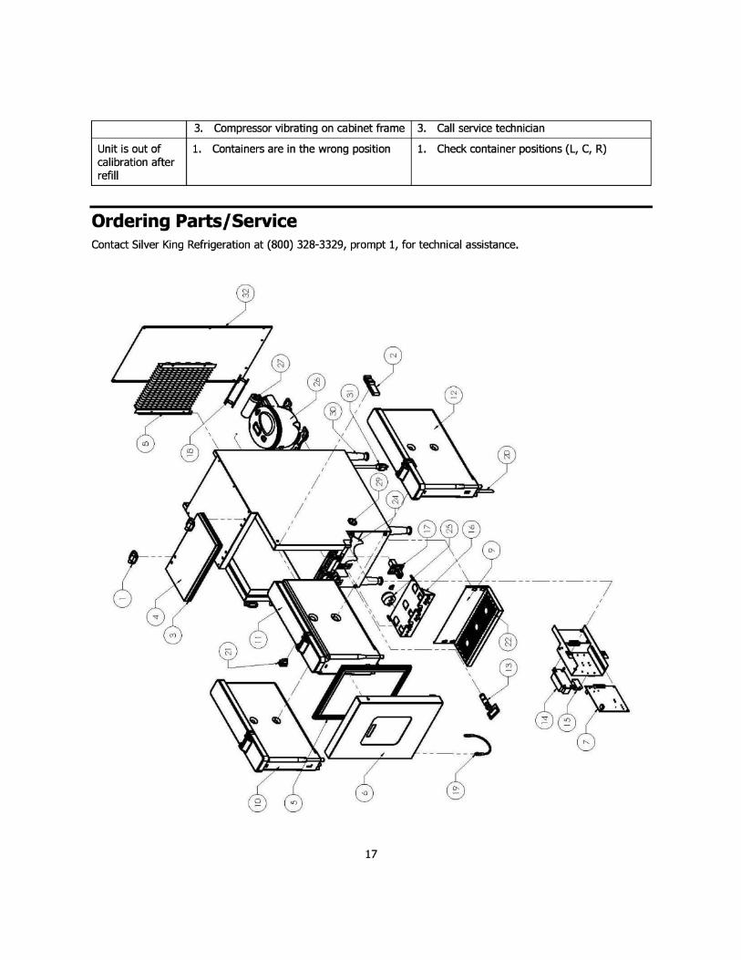
Ordering Parts/Service Contact Silver King Refrigeration at (800) 328-3329, prompt 1, for technical assistance.
17

REPLACEMENT PARTS LIST - SKECD12-V3
ITEMNO_ PART DESCRIPTION PART NO_ 1 HINGE W/ SCREWS AND COVERS 25226 2 LATCH 25227 3 LID GASKET 36954 4 LID ASSEMBLY 36955 5 DOOR GASKET 36956 6 DOOR ASS EMBLY 36957 7 CONTROL BOARD 36992 8 CONDENSER COIL 37016 9 PLATFORM FOR DRIP TRAY 37052 10 CONTAINER ASSEMBLY LEFT 37068 11 CONTAINER ASSEMBLY CENTER 37069 12 CONTAINER ASSEMBLY RIGHT 37070 13 VALVE PINCH ASSEMBLY 811-074 14 POWER SUPPLY 37146 15 RELAY 37147 16 SOLENOID RACK BRACKET ASSEMBLY 37461 17 LOAD CELL ASSEMBLY 37168 18 CONDENSER FAN 11 5V/230V 43832 19 CONNECTOR DOOR DISPLAY 37210 20 3" TUBES /CARTON OF 300\ 37222 21 POWER SWITCH 39564 22 DRIP TRAY 37281 23 TEMPERATURE PROBE (NOT SHOWN) 37364 24 UPPER CUP GUIDE 37436 25 SOLENOID 39543
26 COMPRESSOR KIT 115V/60HZ (W/ELECTRICALS AND DRIER) 11700-12 COMPRESSOR KIT 230V/50-60HZ (W/ELECTRICALS AND DRIER} 11700-13
27 ELECTRICAL KIT 115V /RELAY & OVERLOAD\ 11701-12 ELECTRICAL KIT 230V (RELAY & OVERLOAD) 11701-13
28 CAPILLARY TUBE (NOT SHOWN\ 99035 29 USB HOLE PLUG - 1" DIA 37358 30 4" LEG KIT 38493
POWER CORD 11 5V TYPE B 33883
31 POWER CORD 230V TYPE D 72-464 POWER CORD 230V TYPE F 72-200-1 POWER CORD 230V TYPE N 72-468
32 BACK PANEL 36710
FORM 43880
18

.... 1.0
LO
LE CENT
RIG
DATA CABLE
TO DOOR
C F
BLACKL [-) RED[+)
BLACK a- 4 POWER WHITE 1-) 3 SUPPLY
RED[+) T RED
24V DC 120V AC GROUND t-- OUT IN GRAY I TEMP
I SENSOR CONTROL
AD CELLS BOARD FT - BLACK ~ ~-.o't.:~~•..-:· ml ltl
I ~ a BATTERY I • •
S• ~ • D :· CR2032H HT l1Llt ... ~ .. O= = E •-•« - .. SOLENOID lo. a= . .
RELAYS CONNECTOR lllUE ----: I#]
BOARD IIRCJWN lllUE ... 2 BROWN
6\ UE ~ #:J CIRCJWN !'HUE -
Ill.OWN . c:::::::J
DISPLAY AS VIEWED
FROM FRONT OF MACHINE
.
BLACK '? OVERLOAD COMP )ND -= \N r iii
COMPRESSOR . RELAY
.
REJ...AY ~..,. r
SKECD12-V3
43876 REV: A
RED
,I
RED
WHITE
-nSOLENOIDS 1,f• -
- #1 LEFT lllA.C~ - AS VIEWED l?EO _ WI-IIE
1 #2 CENTER FROM FRONT BtA.O::. -
WI-IIE ~ OF MACHINE RED _...
_ #3 RIGHT lllA.C~ -
RED
WHITE TE~~~ FUSE BLOCK RED ~ BLACK T10Al250VP
- - POWER I / .rr-WHITE POWER GROUND SWITCH - -
CORD