and 1098h-egr pilot-operated regulators valve link reguladores/1098egr... · the type 1098-egr and...
TRANSCRIPT
W3417
�
January 1982 Bulletin 71.2:1098-EGR
Type VL1000 FIELDVUE Valve Link
Fisher Controls
�
Type 1098-EGRand 1098H-EGRPilot-Operated Regulators
�
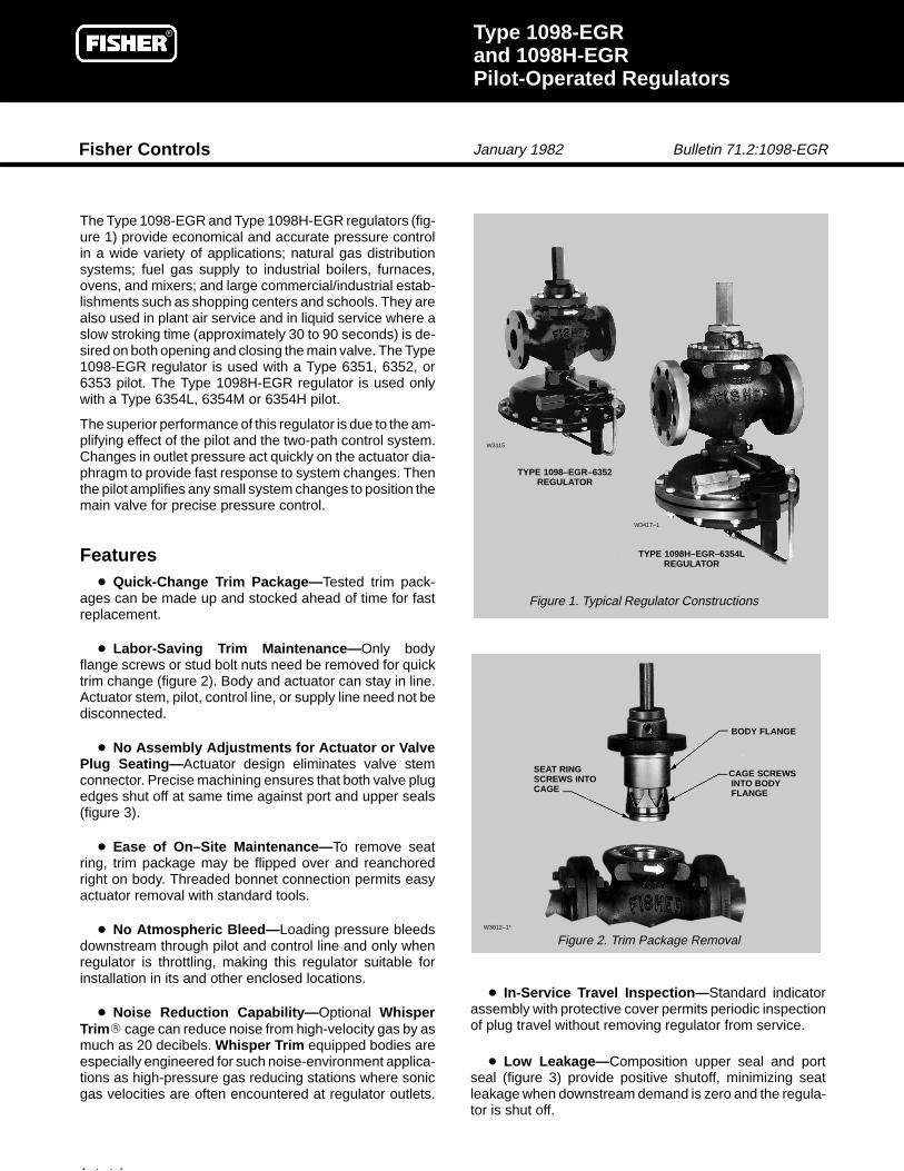
The Type 1098-EGR and Type 1098H-EGR regulators (fig-ure 1) provide economical and accurate pressure controlin a wide variety of applications; natural gas distributionsystems; fuel gas supply to industrial boilers, furnaces,ovens, and mixers; and large commercial/industrial estab-lishments such as shopping centers and schools. They arealso used in plant air service and in liquid service where aslow stroking time (approximately 30 to 90 seconds) is de-sired on both opening and closing the main valve. The Type1098-EGR regulator is used with a Type 6351, 6352, or6353 pilot. The Type 1098H-EGR regulator is used onlywith a Type 6354L, 6354M or 6354H pilot.
The superior performance of this regulator is due to the am-plifying effect of the pilot and the two-path control system.Changes in outlet pressure act quickly on the actuator dia-phragm to provide fast response to system changes. Thenthe pilot amplifies any small system changes to position themain valve for precise pressure control.
W
Figure 1. Typical Regulator Constructions
TYP
W3012–1*
Features� Quick-Change Trim Package— Tested trim pack-
ages can be made up and stocked ahead of time for fastreplacement.
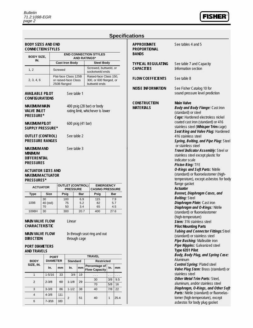
� Labor-Saving Trim Maintenance— Only bodyflange screws or stud bolt nuts need be removed for quicktrim change (figure 2). Body and actuator can stay in line.Actuator stem, pilot, control line, or supply line need not bedisconnected.
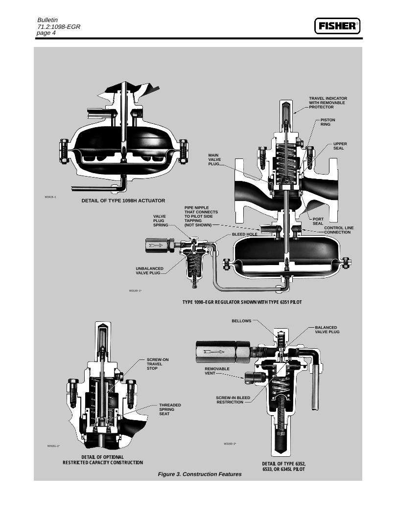
� No Assembly Adjustments for Actuator or ValvePlug Seating— Actuator design eliminates valve stemconnector. Precise machining ensures that both valve plugedges shut off at same time against port and upper seals(figure 3).
� Ease of On–Site Maintenance— To remove seatring, trim package may be flipped over and reanchoredright on body. Threaded bonnet connection permits easyactuator removal with standard tools.
� No Atmospheric Bleed— Loading pressure bleedsdownstream through pilot and control line and only whenregulator is throttling, making this regulator suitable forinstallation in its and other enclosed locations.
� Noise Reduction Capability— Optional WhisperTrim� cage can reduce noise from high-velocity gas by asmuch as 20 decibels. Whisper Trim equipped bodies areespecially engineered for such noise-environment applica-tions as high-pressure gas reducing stations where sonicgas velocities are often encountered at regulator outlets.
footnote here
� In-Service Travel Inspection— Standard indicatorassembly with protective cover permits periodic inspectionof plug travel without removing regulator from service.
� Low Leakage— Composition upper seal and portseal (figure 3) provide positive shutoff, minimizing seatleakage when downstream demand is zero and the regula-tor is shut off.
TYPE 1098–EGR–6352REGULATOR
3115
E 1098H–EGR–6354LREGULATOR
–1
SEAT RINGSCREWS INTOCAGE
BODY FLANGE
CAGE SCREWSINTO BODYFLANGE
Figure 2. Trim Package Removal
�
page 2
Bulletin71.2:1098-EGR
Specifications
BODY SIZES AND ENDCONNECTION STYLES
BODY SIZE,IN.
END CONNECTION STYLESAND RATINGS*
IN.Cast Iron Body Steel Body
1, 2 Screwed Screwed, buttweld, orsocketweld ends
2, 3, 4, 6Flat-face Class 125Bor raised-face Class250B flanged
Raised-face Class 150,300, or 600 flanged, orbuttweld ends
AVAILABLE PILOT See table 1CONFIGURATIONS
MAXIMUM MAIN 400 psig (28 bar) or bodyVALVE INLET rating limit, whichever is lowerPRESSURE*
MAXIMUM PILOT 600 psig (41 bar)SUPPLY PRESSURE*
OUTLET (CONTROL) See table 2PRESSURE RANGES
MAXIMUM AND See table 3MINIMUMDIFFERENTIALPRESSURES
ACTUATOR SIZES ANDMAXIMUM ACTUATORPRESSURES*
ACTUATOR OUTLET (CONTROL)PRESSURE
EMERGENCYCASING PRESSURE
Type Size Psig Bar Psig Bar
10983040 (std)70
1007550
6.95.23.4
1158265
7.95.74.5
1098H 30 300 20.7 400 27.6
MAIN VALVE FLOW LinearCHARACTERISTIC
MAIN VALVE FLOW In through seat ring and outDIRECTION through cage
PORT DIAMETERSAND TRAVELS
BODYPORT TRAVEL
BODYSIZE IN
ODIAMETER Standard Restricted
SIZE, IN.In. mm In. mm Percentage of
Flow CapacityIn. mm
1 1-5/16 33 3/4 19 . . . . . . . . .
2 2-3/8 60 1-1/8 2930 3/8 9.5
2 2-3/8 60 1-1/8 2970 5/8 16
3 3-3/8 86 1-1/2 38 40 7/8 22
4 4-3/8 1112 51 40 1 25.4
6 7–3/16 1832 51 40 1 25.4
APPROXIMATE See tables 4 and 5PROPORTIONALBANDS
TYPICAL REGULATING See table 7 and CapacityCAPACITIES Information section
FLOW COEFFICIENTS See table 8
NOISE INFORMATION See Fisher Catalog 10 for sound pressure level prediction
CONSTRUCTION Main ValveMATERIALS Body and Body Flange: Cast iron
(standard) or steelCage: Hardened electroless nickelcoated cast iron (standard) or 416 stainless steel (Whisper Trim cage)Seat Ring and Valve Plug: Hardened416 stainless steelSpring, Bolting, and Pipe Plug: Steel or stainless steelTravel Indicator Assembly: Steel orstainless steel except plastic for indicator scalePiston Ring: TFEO-Rings and Soft Parts: Nitrile (standard) or fluoroelastomer (high-temperature), except asbestos for bodyflange gasketActuatorBonnet, Diaphragm Cases, and Bolting: SteelDiaphragm Plate: Cast ironDiaphragm and O-Rings: Nitrile (standard) or fluoroelastomer(high-temperature)Stem: 316 stainless steelPilot Mounting PartsTubing and Connector Fittings:Steel(standard) or stainless steelPipe Bushing: Malleable ironPipe Nipples: Galvanized steelType 6351 PilotBody, Body Plug, and Spring Case:AluminumControl Spring: Plated steelValve Plug Stem: Brass (standard) orstainless steelOther Metal Trim Parts: Steel, aluminum, and/or stainless steelDiaphragm, O-Rings, and Other SoftParts: Nitrile (standard) or fluoroelas-tomer (high-temperature), except asbestos for body plug gasket
page 3
Bulletin71.2:1098-EGR
Specifications (Continued)
Type 6352, 6353, 6354L,6354M, or 6354H PilotBody, Body Plug, Spring Case, and Closing Cap: Aluminum (standard), brass, steel, or stain-less steelControl Spring: Plated steelBellows Assembly: Nickel and stainless steelType 6352 Diaphragm: Naturalrubber�Types 6353, 6354L, 6354M, or 6354H Diaphragm: NitrileType 6354M and 6354H Diaphragm Limiter: AluminumO-Rings and Other Soft Parts: Nitrile (standard) or fluoroelastomer (high-temperature), except asbestos for body plug and closing cap gas-ketsFilter: Brass (Type P594-1 standard)or aluminum (Type P593-1), exceptcellulose for filter element and asbestos for gasketPilot and Actuator Vents: Zinc/stainless steel
MATERIAL Standard Elastomers: –20�F to TEMPERATURE 150�F (–29�C to 66�C)CAPABILITIES* High-Temperature Elastomers: 0�F
to 300�F (–18� to 149�C), except 0 to 180�F (–18 to 82�C) for waterservice
*The pressure/temperature limits in this bulletin, and any applicable ANSI standard limitation,should not be exceeded.
PRESSURE See figure 8CONNECTIONS
APPROXIMATE Type 1098 ActuatorWEIGHTS (WITH � Size 30STANDARD SINGLE- 1 In. Body: 55 lb (25 kg)PILOT 2 In. Body: 75 lb (34 kg)CONSTRUCTION) 3 In. Body: 115 lb (52 kg)
4 In. Body: 165 lb (75 kg)6 In. Body: 350 lb (159 kg)� Size 40 (Standard)1 In. Body: 65 lb (29 kg)2 In. Body: 85 lb (39 kg)3 In. Body: 125 lb (57 kg)4 In. Body: 175 lb (79 kg)6 In. Body: 360 lb (163 kg)� Size 701 In. Body: 140 lb (64 kg)2 In. Body: 160 lb (73 kg)3 In. Body: 200 lb (91 kg)4 In. Body: 250 lb (113 kg)6 In. Body: 435 lb (197 kg)Type 1098H Size 30 Actuator1 In. Body: 80 lb (36 kg)2 In. Body: 100 lb (45 kg)3 In. Body: 140 lb (64 kg)4 In. Body: 190 lb (86 kg)6 In. Body: 375 lb (170 kg)
ADDITIONAL OPTIONS See Construction Features section
�Consult your Fisher sales office or sales representative for nitrile and other optional materials.
Table 1. Available Pilot Configurations
CONSTRUCTIONTYPE NUMBER
CONSTRUCTION6351 6352 6353 6354L, 6354M, or 6354H
Unbalanced pilot valve plug Standard . . . . . . . . .
Balanced pilot valve plug . . . Standard Standard Standard
Aluminum spring case with drilled vent and without closing cap Standard Optional Optional Optional
1/4 i 18 NPT t d i ith
Aluminum . . . Standard Standard Standard
1/4 in. 18-NPT tapped spring case with Brass . . . Optional Optional Optional/ 8 pp p gclosing cap and removable vent Steel . . . Optional Optional Optional
Stainless Steel . . . Optional Optional Optional
Pil t t i ti
Standard gain(indicated by S stamped on pilot body and nameplate)
Standard Standard Standard Standard
Pilot restrictionLow gain for liquid service and/or broader proportional bands(indicated by L stamped on pilot body and nameplate)
. . . Optional Optional Optional
High gain for narrower proportional bands(indicated by H stamped on pilot body and nameplate)
. . . Optional Optional Optional
�
page 4
Bulletin71.2:1098-EGR
TRAVEL INDICATORWITH REMOVABLEPROTECTOR
PISTONRING
UPPERSEAL
MAIN VALVEPLUG
Figure 3. Construc
UNBALANCEDVALVE PLUG
VALVEPLUGSPRING
PIPE NIPTHAT COTO PILOTTAPPING(NOT SH
TYPE 109
DETAIL OF TYPE 1098H ACTUATORW3419–1
W3149–1*
PLENNECTS SIDE
OWN)
PORTSEAL
CONTROL LINECONNECTIONBLEED HOLE
BALANCEDVALVE PLUG
BELLOWS
8–EGR REGULATOR SHOWN WITH TYPE 6351 PILOT
DETAIL OF OPTIONALRESTRICTED CAPACITY CONSTRUCTION
THREADED SPRING SEAT
SCREW-ONTRAVELSTOP
W3161–1*
DETAIL OF TYPE 6352,6533, OR 6345L PILOT
SCREW-IN BLEEDRESTRICTION
REMOVABLEVENT
W3160–2*
tion Features
page 5
Bulletin71.2:1098-EGR
ING DATA
Part Number
9860 272127883 270227485 27202
A9672 X012A9673 X012
3925 270227485 27202
3461 274123461 27412A9258 X012
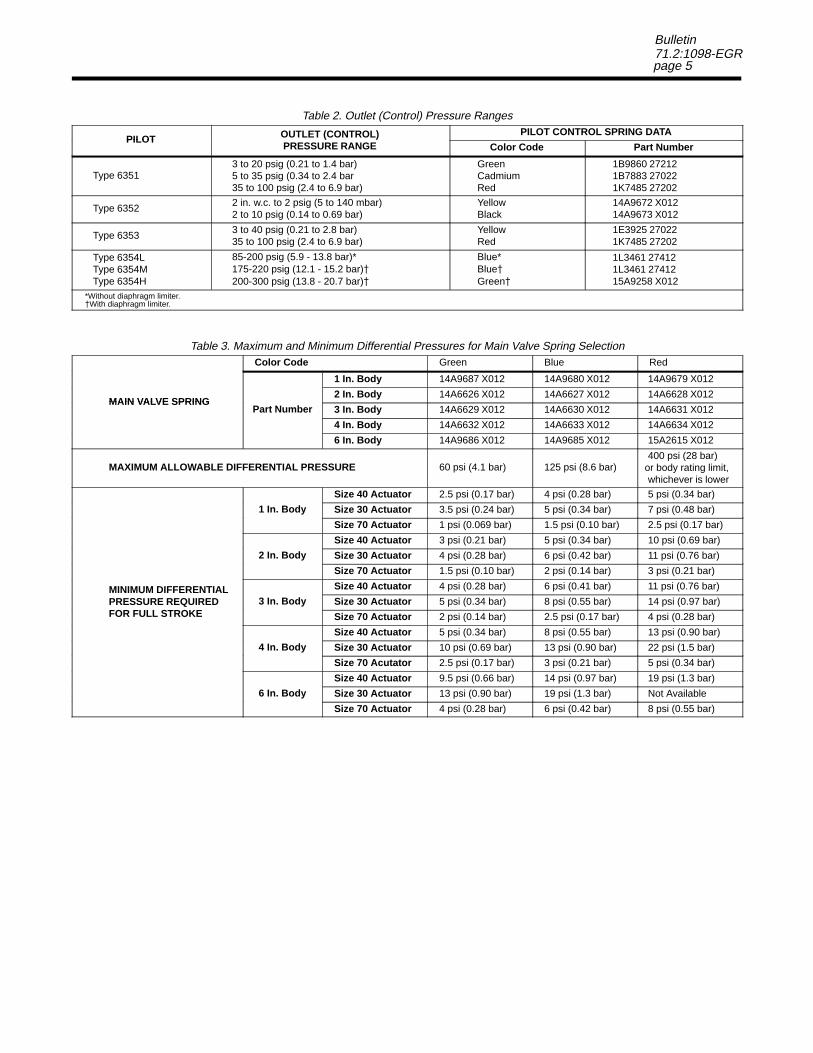
Table 2. Outlet (Control) Pressure Ranges
PILOT OUTLET (CONTROL) PILOT CONTROL SPRPILOT OU (CO O )
PRESSURE RANGE Color Code
Type 63513 to 20 psig (0.21 to 1.4 bar)5 to 35 psig (0.34 to 2.4 bar35 to 100 psig (2.4 to 6.9 bar)
GreenCadmiumRed
1B1B1K
Type 6352 2 in. w.c. to 2 psig (5 to 140 mbar)2 to 10 psig (0.14 to 0.69 bar)
YellowBlack
1414
Type 6353 3 to 40 psig (0.21 to 2.8 bar)35 to 100 psig (2.4 to 6.9 bar)
Yellow Red
1E1K
Type 6354LType 6354MType 6354H
85-200 psig (5.9 - 13.8 bar)*175-220 psig (12.1 - 15.2 bar)�200-300 psig (13.8 - 20.7 bar)�
Blue*Blue�Green�
1L1L15
*Without diaphragm limiter.�With diaphragm limiter.
ed
A9679 X012
A6628 X012
A6631 X012
A6634 X012
A2615 X012
0 psi (28 bar)body rating limit,ichever is lower
psi (0.34 bar)
psi (0.48 bar)
5 psi (0.17 bar)
psi (0.69 bar)
psi (0.76 bar)
psi (0.21 bar)
psi (0.76 bar)
psi (0.97 bar)
psi (0.28 bar)
psi (0.90 bar)
psi (1.5 bar)
psi (0.34 bar)
psi (1.3 bar)
Table 3. Maximum and Minimum Differential Pressures for Main Valve Spring Selection
MAIN VALVE SPRING
Color Code Green Blue R
MAIN VALVE SPRINGP t N b
1 In. Body 14A9687 X012 14A9680 X012 14
MAIN VALVE SPRINGP t N b
2 In. Body 14A6626 X012 14A6627 X012 14MAIN VALVE SPRING
Part Number 3 In. Body 14A6629 X012 14A6630 X012 14
4 In. Body 14A6632 X012 14A6633 X012 14
6 In. Body 14A9686 X012 14A9685 X012 15
MAXIMUM ALLOWABLE DIFFERENTIAL PRESSURE 60 psi (4.1 bar) 125 psi (8.6 bar)40
or wh
MINIMUM DIFFERENTIAL
1 I B d
Size 40 Actuator 2.5 psi (0.17 bar) 4 psi (0.28 bar) 5
MINIMUM DIFFERENTIAL
1 In. Body Size 30 Actuator 3.5 psi (0.24 bar) 5 psi (0.34 bar) 7
MINIMUM DIFFERENTIAL
Size 70 Actuator 1 psi (0.069 bar) 1.5 psi (0.10 bar) 2.
MINIMUM DIFFERENTIAL
2 I B d
Size 40 Actuator 3 psi (0.21 bar) 5 psi (0.34 bar) 10
MINIMUM DIFFERENTIAL
2 In. Body Size 30 Actuator 4 psi (0.28 bar) 6 psi (0.42 bar) 11
MINIMUM DIFFERENTIAL
Size 70 Actuator 1.5 psi (0.10 bar) 2 psi (0.14 bar) 3
MINIMUM DIFFERENTIAL3 I B d
Size 40 Actuator 4 psi (0.28 bar) 6 psi (0.41 bar) 11MINIMUM DIFFERENTIALPRESSURE REQUIREDFOR FULL STROKE
3 In. Body Size 30 Actuator 5 psi (0.34 bar) 8 psi (0.55 bar) 14FOR FULL STROKE Size 70 Actuator 2 psi (0.14 bar) 2.5 psi (0.17 bar) 4
4 I B d
Size 40 Actuator 5 psi (0.34 bar) 8 psi (0.55 bar) 13
4 In. Body Size 30 Actuator 10 psi (0.69 bar) 13 psi (0.90 bar) 22
Size 70 Acutator 2.5 psi (0.17 bar) 3 psi (0.21 bar) 5
Size 40 Actuator 9.5 psi (0.66 bar) 14 psi (0.97 bar) 19
6 I B d6 In. Body Size 30 Actuator 13 psi (0.90 bar) 19 psi (1.3 bar) Not Available
Size 70 Actuator 4 psi (0.28 bar) 6 psi (0.42 bar) 8 psi (0.55 bar)
�
page 6
Bulletin71.2:1098-EGR
BB
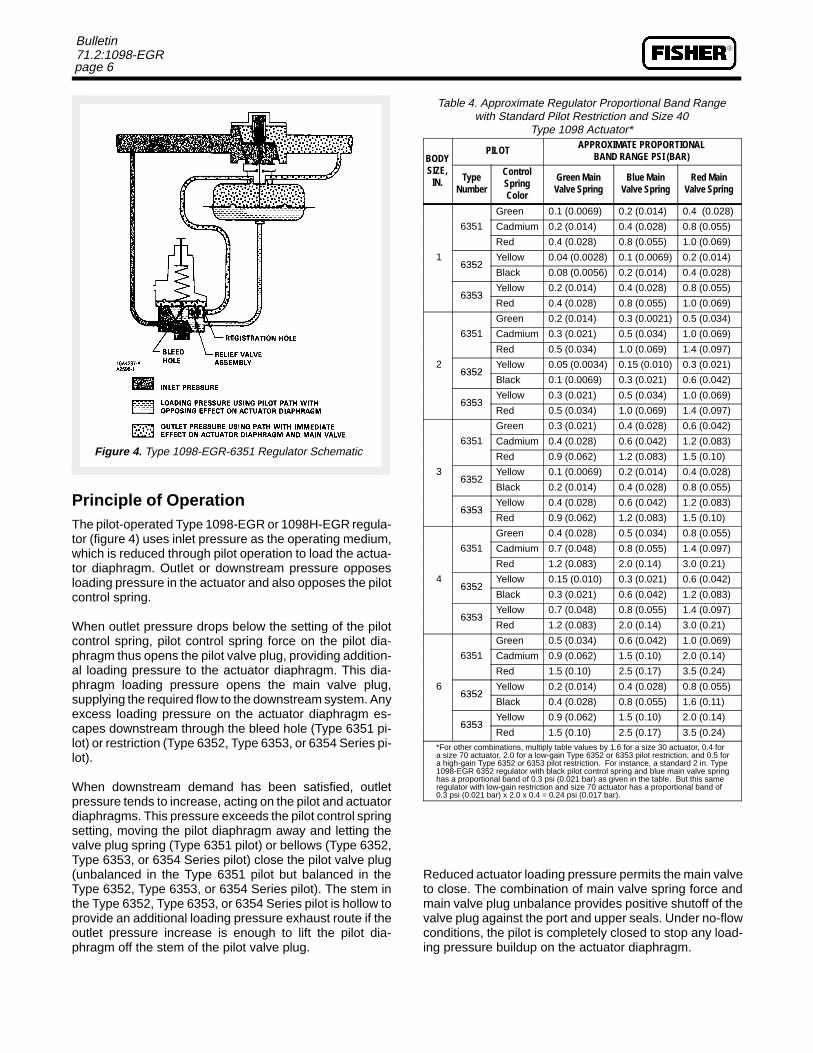
Figure 4. Type 1098-EGR-6351 Regulator Schematic
SIZE,SIZE,IN.
N
1111
2222
Table 4. Approximate Regulator Proportional Band Rangewith Standard Pilot Restriction and Size 40
Type 1098 Actuator*
ODYPILOT APPROXIMATE PROPORTIONAL
BAND RANGE PSI (BAR)ODY
Typeumber
ControlSpringColor
Green MainValve Spring
Blue MainValve Spring
Red MainValve Spring
6351
Green 0.1 (0.0069) 0.2 (0.014) 0.4 (0.028)
6351 Cadmium 0.2 (0.014) 0.4 (0.028) 0.8 (0.055)
Red 0.4 (0.028) 0.8 (0.055) 1.0 (0.069)
6352Yellow 0.04 (0.0028) 0.1 (0.0069) 0.2 (0.014)
6352Black 0.08 (0.0056) 0.2 (0.014) 0.4 (0.028)
6353Yellow 0.2 (0.014) 0.4 (0.028) 0.8 (0.055)
6353Red 0.4 (0.028) 0.8 (0.055) 1.0 (0.069)
6351
Green 0.2 (0.014) 0.3 (0.0021) 0.5 (0.034)
6351 Cadmium 0.3 (0.021) 0.5 (0.034) 1.0 (0.069)
Red 0.5 (0.034) 1.0 (0.069) 1.4 (0.097)
6352Yellow 0.05 (0.0034) 0.15 (0.010) 0.3 (0.021)
6352Black 0.1 (0.0069) 0.3 (0.021) 0.6 (0.042)
6353Yellow 0.3 (0.021) 0.5 (0.034) 1.0 (0.069)
6353Red 0.5 (0.034) 1.0 (0.069) 1.4 (0.097)
3
6351
Green 0.3 (0.021) 0.4 (0.028) 0.6 (0.042)
3
6351 Cadmium 0.4 (0.028) 0.6 (0.042) 1.2 (0.083)
3
Red 0.9 (0.062) 1.2 (0.083) 1.5 (0.10)
36352
Yellow 0.1 (0.0069) 0.2 (0.014) 0.4 (0.028)6352
Black 0.2 (0.014) 0.4 (0.028) 0.8 (0.055)
6353Yellow 0.4 (0.028) 0.6 (0.042) 1.2 (0.083)
6353Red 0.9 (0.062) 1.2 (0.083) 1.5 (0.10)
4
6351
Green 0.4 (0.028) 0.5 (0.034) 0.8 (0.055)
4
6351 Cadmium 0.7 (0.048) 0.8 (0.055) 1.4 (0.097)
4
Red 1.2 (0.083) 2.0 (0.14) 3.0 (0.21)
46352
Yellow 0.15 (0.010) 0.3 (0.021) 0.6 (0.042)6352
Black 0.3 (0.021) 0.6 (0.042) 1.2 (0.083)
6353Yellow 0.7 (0.048) 0.8 (0.055) 1.4 (0.097)
6353Red 1.2 (0.083) 2.0 (0.14) 3.0 (0.21)
6
6351
Green 0.5 (0.034) 0.6 (0.042) 1.0 (0.069)
6
6351 Cadmium 0.9 (0.062) 1.5 (0.10) 2.0 (0.14)
6
Red 1.5 (0.10) 2.5 (0.17) 3.5 (0.24)
66352
Yellow 0.2 (0.014) 0.4 (0.028) 0.8 (0.055)6352
Black 0.4 (0.028) 0.8 (0.055) 1.6 (0.11)
6353Yellow 0.9 (0.062) 1.5 (0.10) 2.0 (0.14)
6353Red 1.5 (0.10) 2.5 (0.17) 3.5 (0.24)
*For other combinations, multiply table values by 1.6 for a size 30 actuator, 0.4 fora size 70 actuator, 2.0 for a low-gain Type 6352 or 6353 pilot restriction, and 0.5 fora high-gain Type 6352 or 6353 pilot restriction. For instance, a standard 2 in. Type1098-EGR 6352 regulator with black pilot control spring and blue main valve springhas a proportional band of 0.3 psi (0.021 bar) as given in the table. But this sameregulator with low-gain restriction and size 70 actuator has a proportional band of0.3 psi (0.021 bar) x 2.0 x 0.4 = 0.24 psi (0.017 bar).
Principle of OperationThe pilot-operated Type 1098-EGR or 1098H-EGR regula-tor (figure 4) uses inlet pressure as the operating medium,which is reduced through pilot operation to load the actua-tor diaphragm. Outlet or downstream pressure opposesloading pressure in the actuator and also opposes the pilotcontrol spring.
When outlet pressure drops below the setting of the pilotcontrol spring, pilot control spring force on the pilot dia-phragm thus opens the pilot valve plug, providing addition-al loading pressure to the actuator diaphragm. This dia-phragm loading pressure opens the main valve plug,supplying the required flow to the downstream system. Anyexcess loading pressure on the actuator diaphragm es-capes downstream through the bleed hole (Type 6351 pi-lot) or restriction (Type 6352, Type 6353, or 6354 Series pi-lot).
When downstream demand has been satisfied, outletpressure tends to increase, acting on the pilot and actuatordiaphragms. This pressure exceeds the pilot control springsetting, moving the pilot diaphragm away and letting thevalve plug spring (Type 6351 pilot) or bellows (Type 6352,Type 6353, or 6354 Series pilot) close the pilot valve plug(unbalanced in the Type 6351 pilot but balanced in theType 6352, Type 6353, or 6354 Series pilot). The stem inthe Type 6352, Type 6353, or 6354 Series pilot is hollow toprovide an additional loading pressure exhaust route if theoutlet pressure increase is enough to lift the pilot dia-phragm off the stem of the pilot valve plug.
Reduced actuator loading pressure permits the main valveto close. The combination of main valve spring force andmain valve plug unbalance provides positive shutoff of thevalve plug against the port and upper seals. Under no-flowconditions, the pilot is completely closed to stop any load-ing pressure buildup on the actuator diaphragm.
page 7
Bulletin71.2:1098-EGR
Table 5. Approximate Regulator Proportional Band Range with Standard Pilot Restriction and Size 30 Type 1098H Actuator*
BODY SIZE,PILOT APPROXIMATE PROPORTIONAL
BAND RANGE, PSI (BAR)O S ,IN. Type
NumberConrol
Spring ColorGreen Main
Valve SpringBlue Main
Valve SpringRed Main
Valve Spring
1 6354L, 6354M, or 6354H Blue or Green 1.0 (0.07) 1.5 (0.10) 2.5 (0.17)
2 6354L, 6354M, or 6354H Blue or Green 1.5 (0.10) 2.0 (0.14) 3.0 (0.21)
n 2.5 (0.17) 3.0 (0.21) 4.0 (0.28)
n 3.5 (0.24) 4.0 (0.28) 5.0 (0.34)
n 4.0 (0.28) 5.0 (0.34) Not availableBut this same regulator with low-gain restriction has a proportional band of 2.0 psi (0.14 bar) x 2.0 = 4.0 psi (0.28 bar).
3 6354L, 6354M, or 6354H Blue or Gree
4 6354L, 6354M, or 6354H Blue or Gree
6 6354L, 6354M, or 6354H Blue or Gree*For other restrictions, multiply table values by 2.0 for a low-gain restriction or by 0.5 for a high gainrestriction. For instance, a standard 2 in. Type 1098H-EGR-6354L regulator with blue controlspring and blue main valve spring has a proportional band of 2.0 psi (0.14 bar) as given in the table.
To protect the Type 1098 and Type 1098H actuator dia-phragms from excessive differential pressure, all pilotshave a relief valve that allows loading pressure to bleeddownstream at approximately 25 psi (1.7 bar) differentialacross the actuator diaphragm.
Construction FeaturesPilots for Application Versatility
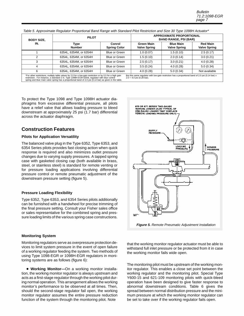
The balanced valve plug in the Type 6352, Type 6353, and6354 Series pilots provides fast closing action when quickresponse is required and also minimizes outlet pressurechanges due to varying supply pressures. A tapped springcase with gasketed closing cap (both available in brass,steel, or stainless steel) is standard for remote venting orfor pressure loading applications involving differentialpressure control or remote pneumatic adjustment of thedownstream pressure setting (figure 5).
Pressure Loading Flexibility
Type 6352, Type 6353, and 6354 Series pilots additionallycan be furnished with a handwheel for precise trimming ofthe final pressure setting. Consult your Fisher sales officeor sales representative for the combined spring and pres-sure loading limits of the various spring case constructions.
Monitoring System
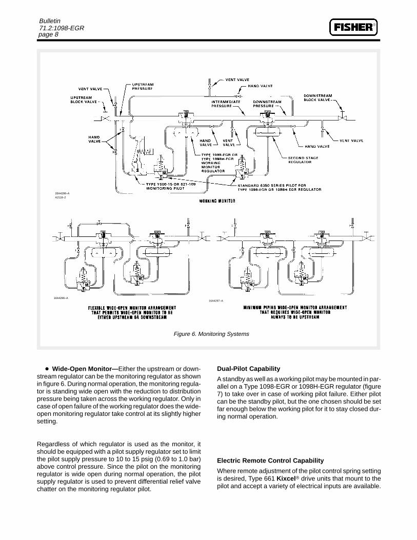
Monitoring regulators serve as overpressure protection de-vices to limit system pressure in the event of open failureof a working regulator feeding the system. Two methods ofusing Type 1098-EGR or 1098H-EGR regulators in moni-toring systems are as follows (figure 6):
� Working Monitor— On a working monitor installa-tion, the working monitor regulator is always upstream andacts as a first-stage regulator through the working pilot dur-ing normal operation. This arrangement allows the workingmonitor’s performance to be observed at all times. Then,should the second-stage regulator fail open, the workingmonitor regulator assumes the entire pressure reductionfunction of the system through the monitoring pilot. Note
that the working monitor regulator actuator must be able towithstand full inlet pressure or be protected from it in casethe working monitor fails wide open.
The monitoring pilot must be upstream of the working mon-itor regulator. This enables a close set point between theworking regulator and the monitoring pilot. Special TypeY600-15 and 621-109 monitoring pilots with quick-bleedoperation have been designed to give faster response toabnormal downstream conditions. Table 6 gives thespread between normal distribution pressure and the mini-mum pressure at which the working monitor regulator canbe set to take over if the working regulator fails open.
Figure 5. Remote Pneumatic Adjustment Installation
�
page 8
Bulletin71.2:1098-EGR
Figure 6. Monitoring Systems
26A4298–A
A2118–2
16A4296–A16A4297–A
� Wide-Open Monitor— Either the upstream or down-stream regulator can be the monitoring regulator as shownin figure 6. During normal operation, the monitoring regula-tor is standing wide open with the reduction to distributionpressure being taken across the working regulator. Only incase of open failure of the working regulator does the wide-open monitoring regulator take control at its slightly highersetting.
Regardless of which regulator is used as the monitor, itshould be equipped with a pilot supply regulator set to limitthe pilot supply pressure to 10 to 15 psig (0.69 to 1.0 bar)above control pressure. Since the pilot on the monitoringregulator is wide open during normal operation, the pilotsupply regulator is used to prevent differential relief valvechatter on the monitoring regulator pilot.
Dual-Pilot Capability
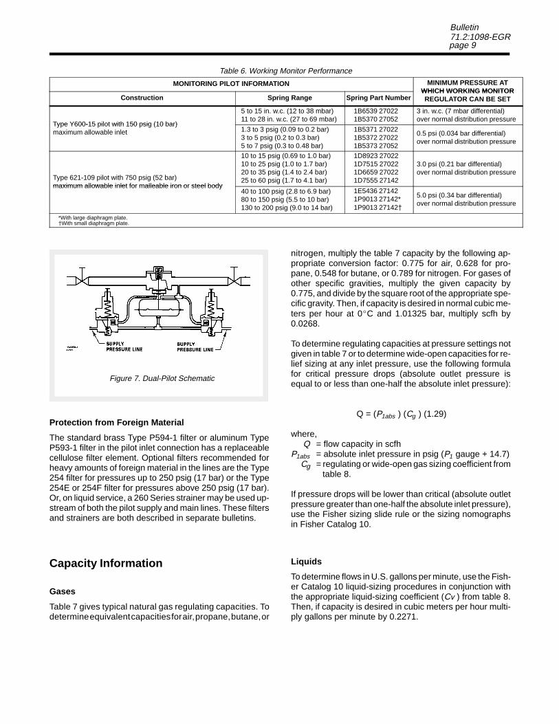
A standby as well as a working pilot may be mounted in par-allel on a Type 1098-EGR or 1098H-EGR regulator (figure7) to take over in case of working pilot failure. Either pilotcan be the standby pilot, but the one chosen should be setfar enough below the working pilot for it to stay closed dur-ing normal operation.
Electric Remote Control Capability
Where remote adjustment of the pilot control spring settingis desired, Type 661 Kixcel � drive units that mount to thepilot and accept a variety of electrical inputs are available.
page 9
Bulletin71.2:1098-EGR
Table 6. Working Monitor Performance
MONITORING PILOT INFORMATION MINIMUM PRESSURE ATWHICH WORKING MONITOR
Construction Spring Range Spring Part NumberWHICH WORKING MONITORREGULATOR CAN BE SET
Type Y600-15 pilot with 150 psig (10 bar)
5 to 15 in. w.c. (12 to 38 mbar)11 to 28 in. w.c. (27 to 69 mbar)
1B6539 270221B5370 27052
3 in. w.c. (7 mbar differential)over normal distribution pressure
Type Y600-15 pilot with 150 psig (10 bar)maximum allowable inlet 1.3 to 3 psig (0.09 to 0.2 bar)
3 to 5 psig (0.2 to 0.3 bar)5 to 7 psig (0.3 to 0.48 bar)
1B5371 270221B5372 270221B5373 27052
0.5 psi (0.034 bar differential)over normal distribution pressure
Type 621-109 pilot with 750 psig (52 bar)maximum allowable inlet for malleable iron or steel body
10 to 15 psig (0.69 to 1.0 bar)10 to 25 psig (1.0 to 1.7 bar)20 to 35 psig (1.4 to 2.4 bar)25 to 60 psig (1.7 to 4.1 bar)
1D8923 270221D7515 270221D6659 270221D7555 27142
3.0 psi (0.21 bar differential)over normal distribution pressure
maximum allowable inlet for malleable iron or steel body40 to 100 psig (2.8 to 6.9 bar)80 to 150 psig (5.5 to 10 bar)130 to 200 psig (9.0 to 14 bar)
1E5436 271421P9013 27142*1P9013 27142�
5.0 psi (0.34 bar differential)over normal distribution pressure
*With large diaphragm plate.�With small diaphragm plate.
Figure 7. Dual-Pilot Schematic
Protection from Foreign Material
The standard brass Type P594-1 filter or aluminum TypeP593-1 filter in the pilot inlet connection has a replaceablecellulose filter element. Optional filters recommended forheavy amounts of foreign material in the lines are the Type254 filter for pressures up to 250 psig (17 bar) or the Type254E or 254F filter for pressures above 250 psig (17 bar).Or, on liquid service, a 260 Series strainer may be used up-stream of both the pilot supply and main lines. These filtersand strainers are both described in separate bulletins.
Capacity Information
Gases
Table 7 gives typical natural gas regulating capacities. Todetermine equivalent capacities for air, propane, butane, or
nitrogen, multiply the table 7 capacity by the following ap-propriate conversion factor: 0.775 for air, 0.628 for pro-pane, 0.548 for butane, or 0.789 for nitrogen. For gases ofother specific gravities, multiply the given capacity by0.775, and divide by the square root of the appropriate spe-cific gravity. Then, if capacity is desired in normal cubic me-ters per hour at 0�C and 1.01325 bar, multiply scfh by0.0268.
To determine regulating capacities at pressure settings notgiven in table 7 or to determine wide-open capacities for re-lief sizing at any inlet pressure, use the following formulafor critical pressure drops (absolute outlet pressure isequal to or less than one-half the absolute inlet pressure):
Q = (P1abs ) (Cg ) (1.29)
where, Q = flow capacity in scfh P1abs = absolute inlet pressure in psig (P1 gauge + 14.7) Cg = regulating or wide-open gas sizing coefficient from table 8.
If pressure drops will be lower than critical (absolute outletpressure greater than one-half the absolute inlet pressure),use the Fisher sizing slide rule or the sizing nomographsin Fisher Catalog 10.
Liquids
To determine flows in U.S. gallons per minute, use the Fish-er Catalog 10 liquid-sizing procedures in conjunction withthe appropriate liquid-sizing coefficient (Cv ) from table 8.Then, if capacity is desired in cubic meters per hour multi-ply gallons per minute by 0.2271.
�
page 10
Bulletin71.2:1098-EGR
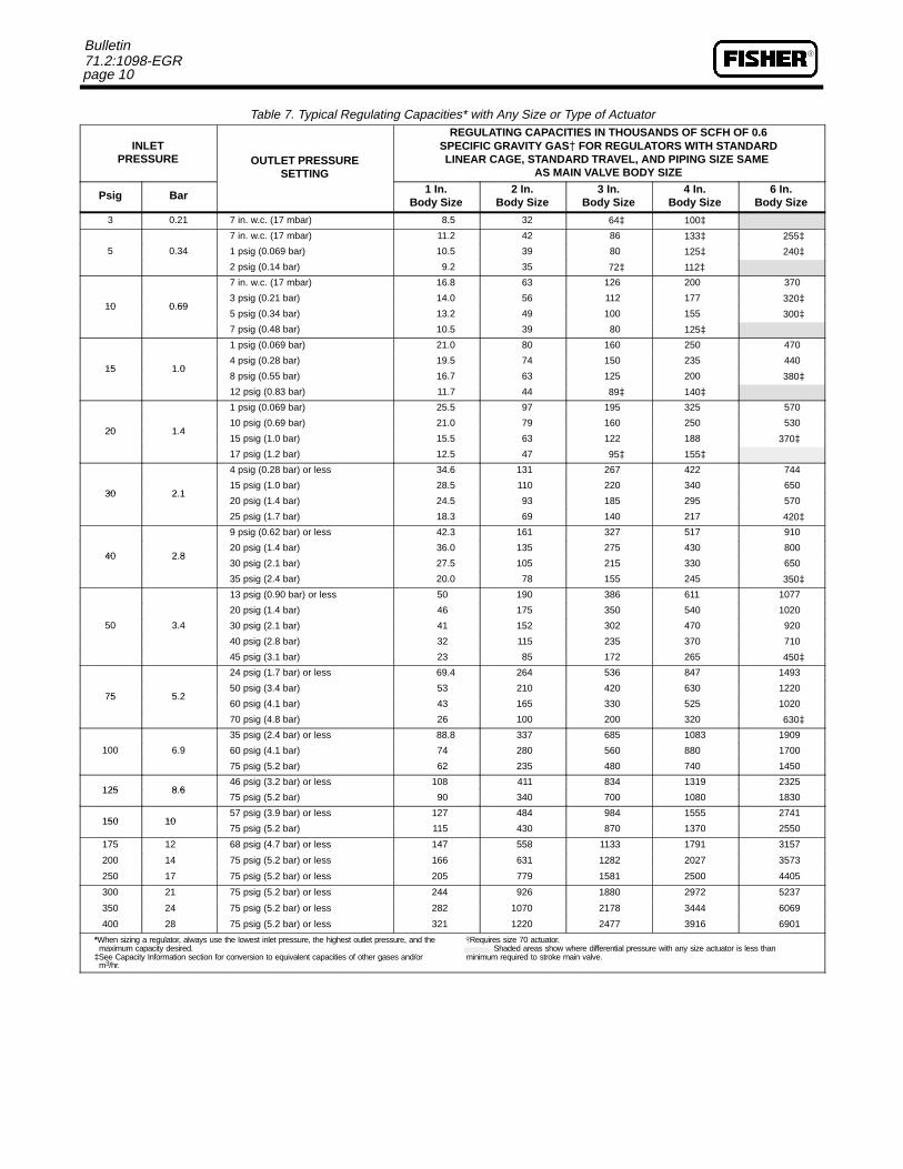
Table 7. Typical Regulating Capacities* with Any Size or Type of Actuator
INLETPRESSURE OUTLET PRESSURE
SETTING
REGULATING CAPACITIES IN THOUSANDS OF SCFH OF 0.6SPECIFIC GRAVITY GAS� FOR REGULATORS WITH STANDARDLINEAR CAGE, STANDARD TRAVEL, AND PIPING SIZE SAME
AS MAIN VALVE BODY SIZE
Psig Bar 1 In.Body Size
2 In.Body Size
3 In.Body Size
4 In.Body Size
6 In.Body Size
3 0.21 7 in. w.c. (17 mbar) 8.5 32 64� 100�
5 0 34
7 in. w.c. (17 mbar) 11.2 42 86 133� 255�
5 0.34 1 psig (0.069 bar) 10.5 39 80 125� 240�
2 psig (0.14 bar) 9.2 35 72� 112�
10 0 69
7 in. w.c. (17 mbar) 16.8 63 126 200 370
10 0 693 psig (0.21 bar) 14.0 56 112 177 320�
10 0.695 psig (0.34 bar) 13.2 49 100 155 300�
7 psig (0.48 bar) 10.5 39 80 125�
15 1 0
1 psig (0.069 bar) 21.0 80 160 250 470
15 1 04 psig (0.28 bar) 19.5 74 150 235 440
15 1.08 psig (0.55 bar) 16.7 63 125 200 380�
12 psig (0.83 bar) 11.7 44 89� 140�
20 1 4
1 psig (0.069 bar) 25.5 97 195 325 570
20 1 410 psig (0.69 bar) 21.0 79 160 250 530
20 1.415 psig (1.0 bar) 15.5 63 122 188 370�
17 psig (1.2 bar) 12.5 47 95� 155�
30 2 1
4 psig (0.28 bar) or less 34.6 131 267 422 744
30 2 115 psig (1.0 bar) 28.5 110 220 340 650
30 2.120 psig (1.4 bar) 24.5 93 185 295 570
25 psig (1.7 bar) 18.3 69 140 217 420�
40 2 8
9 psig (0.62 bar) or less 42.3 161 327 517 910
40 2 820 psig (1.4 bar) 36.0 135 275 430 800
40 2.830 psig (2.1 bar) 27.5 105 215 330 650
35 psig (2.4 bar) 20.0 78 155 245 350�
50 3 4
13 psig (0.90 bar) or less 50 190 386 611 1077
50 3 4
20 psig (1.4 bar) 46 175 350 540 1020
50 3.4 30 psig (2.1 bar) 41 152 302 470 920
40 psig (2.8 bar) 32 115 235 370 710
45 psig (3.1 bar) 23 85 172 265 450�
75 5 2
24 psig (1.7 bar) or less 69.4 264 536 847 1493
75 5 250 psig (3.4 bar) 53 210 420 630 1220
75 5.260 psig (4.1 bar) 43 165 330 525 1020
70 psig (4.8 bar) 26 100 200 320 630�
100 6 9
35 psig (2.4 bar) or less 88.8 337 685 1083 1909
100 6.9 60 psig (4.1 bar) 74 280 560 880 1700
75 psig (5.2 bar) 62 235 480 740 1450
125 8 646 psig (3.2 bar) or less 108 411 834 1319 2325
125 8.675 psig (5.2 bar) 90 340 700 1080 1830
150 1057 psig (3.9 bar) or less 127 484 984 1555 2741
150 1075 psig (5.2 bar) 115 430 870 1370 2550
175 12 68 psig (4.7 bar) or less 147 558 1133 1791 3157
200 14 75 psig (5.2 bar) or less 166 631 1282 2027 3573
250 17 75 psig (5.2 bar) or less 205 779 1581 2500 4405
300 21 75 psig (5.2 bar) or less 244 926 1880 2972 5237
350 24 75 psig (5.2 bar) or less 282 1070 2178 3444 6069
400 28 75 psig (5.2 bar) or less 321 1220 2477 3916 6901
*When sizing a regulator, always use the lowest inlet pressure, the highest outlet pressure, and the �Requires size 70 actuator. maximum capacity desired. Shaded areas show where differential pressure with any size actuator is less than�See Capacity Information section for conversion to equivalent capacities of other gases and/or minimum required to stroke main valve. m3/hr.
page 11
Bulletin71.2:1098-EGR
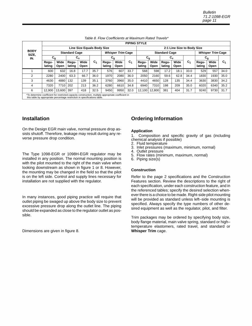
Table 8. Flow Coefficients at Maximum Rated Travels*
BODY
PIPING STYLE
BODYLine Size Equals Body Size 2:1 Line Size to Body Size
BODYSIZE,
Standard Cage Whisper Trim Cage Standard Cage Whisper Trim CageSIZE,
IN. Cg CvC
CgC
Cg CvC
CgC
IN.Regu-lating
WideOpen
Regu-lating
WideOpen
C1 Regu-lating
WideOpen
C1 Regu-lating
WideOpen
Regu-lating
WideOpen
C1 Regu-lating
WideOpen
C1
1 600 632 16.8 17.7 35.7 576 607 33.7 568 598 17.2 18.1 33.0 529 557 34.0
2 2280 2400 63.3 66.7 36.0 1970 2080 36.0 2050 2160 59.6 62.8 34.4 1830 1930 35.0
3 4630 4880 132 139 35.1 3760 3960 35.0 4410 4650 128 135 34.4 3630 3830 34.2
4 7320 7710 202 213 36.2 6280 6610 34.8 6940 7310 198 209 35.0 6020 6340 35.2
6 12,900 13,600 397 418 32.5 9450 9950 32.0 12,100 12,800 381 404 31.7 9240 9730 31.7*To determine coefficient for restricted-capacity construction, multiply appropriate coefficient in this table by appropriate percentage restriction in specifications table.
Installation
On the Design EGR main valve, normal pressure drop as-sists shutoff. Therefore, leakage may result during any re-verse pressure drop condition.
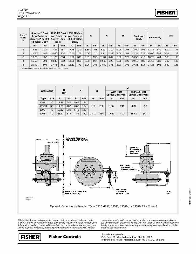
The Type 1098-EGR or 1098H-EGR regulator may beinstalled in any position. The normal mounting position iswith the pilot mounted to the right of the main valve whenlooking downstream as shown in figure 1 or 8. However,the mounting may be changed in the field so that the pilotis on the left side. Control and supply lines necessary forinstallation are not supplied with the regulator.
In many instances, good piping practice will require thatoutlet piping be swaged up above the body size to preventexcessive pressure drop along the outlet line. The pipingshould be expanded as close to the regulator outlet as pos-sible.
Dimensions are given in figure 8.
Ordering Information
Application1. Composition and specific gravity of gas (includingchemical analysis if possible)2. Fluid temperature3. Inlet pressures (maximum, minimum, normal)4. Outlet pressure5. Flow rates (minimum, maximum, normal)6. Piping size(s)
Construction
Refer to the page 2 specifications and the ConstructionFeatures section. Review the descriptions to the right ofeach specification, under each construction feature, and inthe referenced tables; specify the desired selection when-ever there is a choice to be made. Right-side pilot mountingwill be provided as standard unless left–side mounting isspecified. Always specify the type numbers of other de-sired equipment as well as the regulator, pilot, and filter.
Trim packages may be ordered by specifying body size,body flange material, main valve spring, standard or high–temperature elastomers, rated travel, and standard orWhisper Trim cage.
�
page 12
Bulletin71.2:1098-EGR
BODY
A
D G R
Z
ARBODYSIZE,
IN.
Screwed* CastIron Body, or
Screwed* or 600RF Steel Body
125B FF CastIron Body, or150 RF Steel
Body
250B FF CastIron Body, or300 RF Steel
Body
D G R Cast IronBody
Steel BodyAR
In. mm In. mm In. mm In. mm In. mm In. mm In. mm In. mm In. mm
1 8.25 210 7.25 184 7.75 197 3.88 98 8.62 219 4.06 103 12.00 305 13.75 349 3.00 76
2 11.25 286 10.00 254 10.50 267 4.56 116 9.12 232 4.06 103 13.31 338 15.06 383 3.12 79
3 13.25 337 11.75 298 12.50 318 5.31 135 11.31 287 5.06 129 16.50 419 18.25 464 3.88 98
4 15.50 394 13.88 352 14.50 368 6.56 167 12.69 322 5.06 129 19.12 486 21.12 536 5.12 130
6 20.00 508 17.75 451 18.62 473 8.06 205 13.62 346 8.00 203 20.25 514 23.25 591 6.62 168*Screwed body available only in 1-inch and 2-inch sizes.
14A7378–
B1113–1
While this infoFisher Controinformation. Nantee, expres
ACTUATOR C, E HM
ACTUATOR C,DIA
E H With PilotSpring Case Vent
Without PilotSpring Case Vent
Type Size In. mm In. mm In. mm In. mm In. mm
1098 30 11.38 289 5.69 144
7 88 200 9 50 241 9 31 2371098H 30 11.38 289 6.06 154 7.88 200 9.50 241 9.31 237
1098 40 13.12 333 5.75 146
1098 70 21.12 537 7.44 189 14.19 360 15.81 402 15.62 397
A.
Figure 8. Dimensions (
G
U.S
.
������ ���
rmation is presented in good faith and believels does not guarantee satisfactory results fromothing contained herein is to be construed as s or implied, regarding the performance, merc
�
Standard Type 6352, 6353, 6354L, 63
��For information writeP.O. Box 190, Marshor Brenchley House,
d to be accurate, reliance upon sucha warranty or guar-hantability, fitness
or any other matter wituse any product or prothe right, without noticeproducts described he
54M, or 6354H Pilot Shown)
PR
INT
ED
IN
:alltown, Iowa 50158, U.S.A. Maidstone, Kent ME 14 1UQ, England
h respect to the products, nor as a recommendation tocess in conflict with any patent. Fisher Controls reserves, to alter or improve the designs or specifications of the
rein.