manual mapper obm-100 series installation · egr rate programming chart in egr simulation mode to...
TRANSCRIPT
Manual Mapper OBM-100 Series Installation For Manual Mapper Software Version V3.4 and on (September 2018 onwards)
Congratulations on purchasing our Manual Mapper device! And thank you for supporting our 4wd community for better common sense.
Our OBM-100 series Manual Mapper is a fuel trimming device to give you some degree of the control over your car performance from locked up capabilities due to the globalisation of the design in nature. The Manual Mapper is designed for purely as a fuel trimming device with ATT option. ATT (Artificial Turbo-boost Trim) option will enable extra squirt of fuel when you accelerate then go back to your dial setting once you have achieved moving the car from standing still or overtake. It means you can set Mapper dial to -5% for the fuel economy, but when you accelerate it will use the ATT rate setting (from +1 to +20%) to help move on easily. Please read ATT setting safety margins
The unit also has the EGR simulation option to Suspend EGR function for private land, off-road and racing use to stop devastating soot clogging the engine and better breathing for more power or economy.
The unit can be solely used as a just fuel trimming device.
The unit installation is straight forward, Fix the main body to any place engine bay away from heat and bonnet
lift strut damper. Please refer to the photos.
The two connectors coming from Manual Mapper are inserted between the MAF sensor and Car computer on
the air cleaner box. EGR harness is connected from the EGR valve position sensor into the rear of the Manual
Mapper main unit.
All of our units are waterproof, but try to mount as high as possible for longevity of the unit.
Measure the distance between the two holes of the main unit (105 mm) to drill the mounting holes, then uses
self tapping screw to mount the main unit.
*** Caution! ***
Please never drill the holes using the main unit as a template. Many cables are coming out of the position of
the holes and drilling directly through the cable will result in damage of the main unit. The warranty will be
voided on such abuse.
Another way to mount main unit is using thick main wiring loom in a conduit as a mounting point with cable
ties in the engine bay under the windscreen side of the cowling. It is quite okay to use plastic cable ties to fix
the main unit. The main unit weight is only 140g that tied up with two cable ties top of cable loom and has
been in Simpson desert French Line and back to Sydney 5000km without any problems.
Please also beware of the all the car connectors are waterproof. It means it has a rubber seal to prevent water
ingress but making connections a very hard sometimes.
All the connectors do have releasing plastic tab to disengage and you need to push the tab very hard first,
then pull the connector by the housing while you are still pressing the tab hard. Please be very careful not to
damage the plastic connector. Never use a screwdriver to push or pry the connector. They are very easily
damaged.
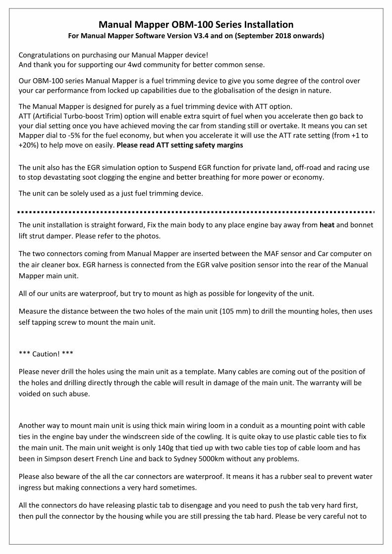
Best Installation of the main unit. Away from heat source such as near exhaust manifold.
Using two self tapping screws.
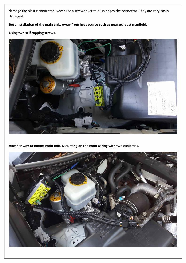
Another way to mount main unit. Mounting on the main wiring with two cable ties.
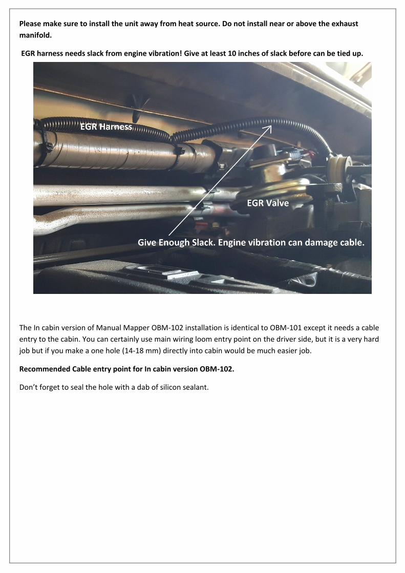
Please make sure to install the unit away from heat source. Do not install near or above the exhaust
manifold.
EGR harness needs slack from engine vibration! Give at least 10 inches of slack before can be tied up.
The In cabin version of Manual Mapper OBM-102 installation is identical to OBM-101 except it needs a cable
entry to the cabin. You can certainly use main wiring loom entry point on the driver side, but it is a very hard
job but if you make a one hole (14-18 mm) directly into cabin would be much easier job.
Recommended Cable entry point for In cabin version OBM-102.
Don’t forget to seal the hole with a dab of silicon sealant.
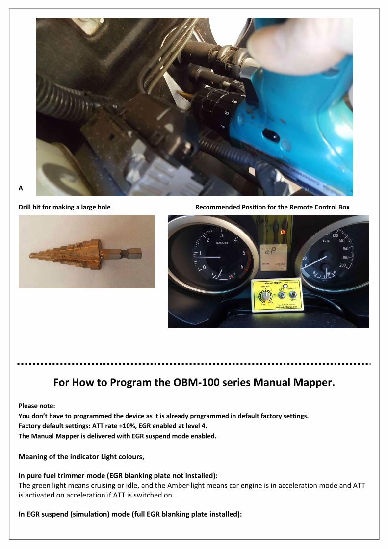
A
Drill bit for making a large hole Recommended Position for the Remote Control Box
For How to Program the OBM-100 series Manual Mapper.
Please note:
You don’t have to programmed the device as it is already programmed in default factory settings.
Factory default settings: ATT rate +10%, EGR enabled at level 4.
The Manual Mapper is delivered with EGR suspend mode enabled.
Meaning of the indicator Light colours, In pure fuel trimmer mode (EGR blanking plate not installed): The green light means cruising or idle, and the Amber light means car engine is in acceleration mode and ATT is activated on acceleration if ATT is switched on. In EGR suspend (simulation) mode (full EGR blanking plate installed):
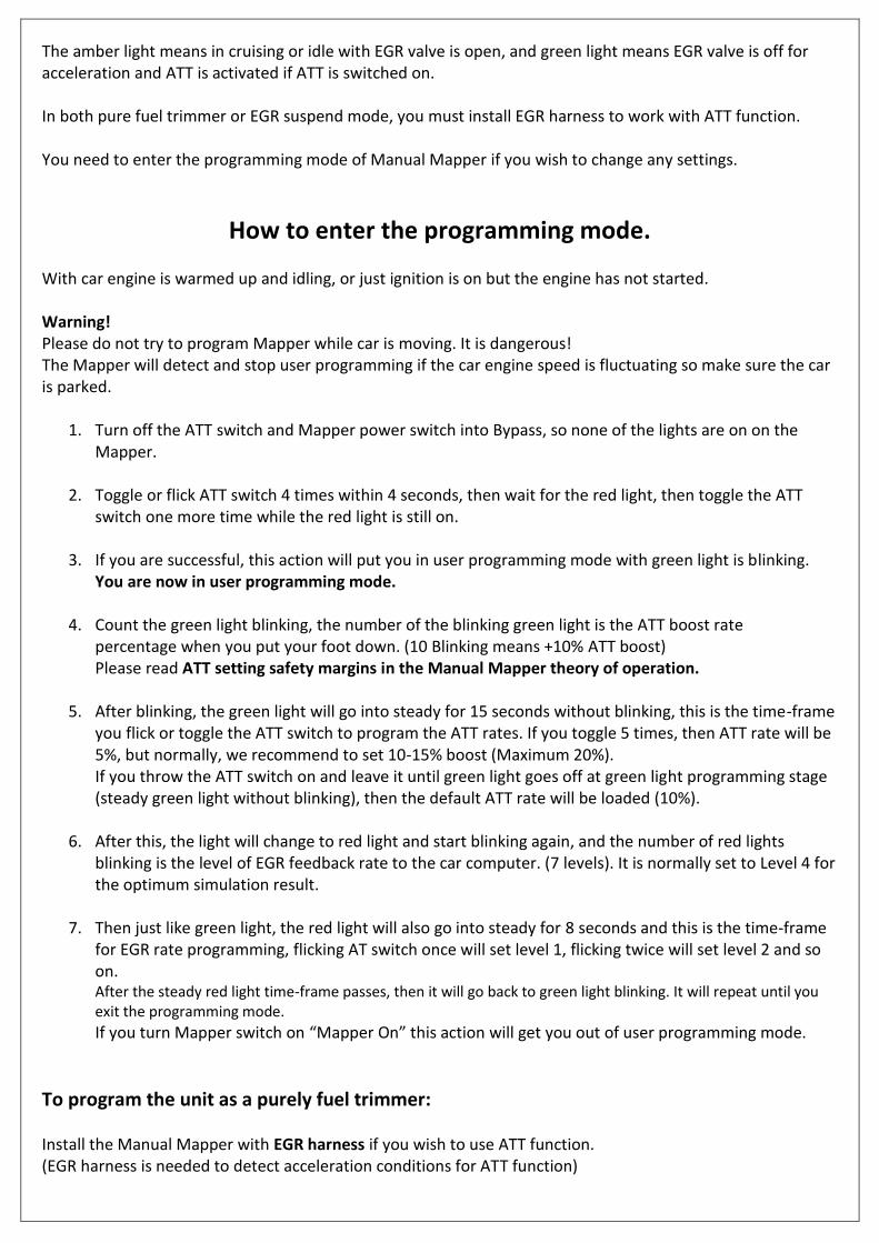
The amber light means in cruising or idle with EGR valve is open, and green light means EGR valve is off for acceleration and ATT is activated if ATT is switched on. In both pure fuel trimmer or EGR suspend mode, you must install EGR harness to work with ATT function. You need to enter the programming mode of Manual Mapper if you wish to change any settings.
How to enter the programming mode. With car engine is warmed up and idling, or just ignition is on but the engine has not started. Warning! Please do not try to program Mapper while car is moving. It is dangerous! The Mapper will detect and stop user programming if the car engine speed is fluctuating so make sure the car is parked.
1. Turn off the ATT switch and Mapper power switch into Bypass, so none of the lights are on on the Mapper.
2. Toggle or flick ATT switch 4 times within 4 seconds, then wait for the red light, then toggle the ATT switch one more time while the red light is still on.
3. If you are successful, this action will put you in user programming mode with green light is blinking.
You are now in user programming mode.
4. Count the green light blinking, the number of the blinking green light is the ATT boost rate percentage when you put your foot down. (10 Blinking means +10% ATT boost) Please read ATT setting safety margins in the Manual Mapper theory of operation.
5. After blinking, the green light will go into steady for 15 seconds without blinking, this is the time-frame you flick or toggle the ATT switch to program the ATT rates. If you toggle 5 times, then ATT rate will be 5%, but normally, we recommend to set 10-15% boost (Maximum 20%). If you throw the ATT switch on and leave it until green light goes off at green light programming stage (steady green light without blinking), then the default ATT rate will be loaded (10%).
6. After this, the light will change to red light and start blinking again, and the number of red lights blinking is the level of EGR feedback rate to the car computer. (7 levels). It is normally set to Level 4 for the optimum simulation result.
7. Then just like green light, the red light will also go into steady for 8 seconds and this is the time-frame for EGR rate programming, flicking AT switch once will set level 1, flicking twice will set level 2 and so on. After the steady red light time-frame passes, then it will go back to green light blinking. It will repeat until you exit the programming mode.
If you turn Mapper switch on “Mapper On” this action will get you out of user programming mode.
To program the unit as a purely fuel trimmer: Install the Manual Mapper with EGR harness if you wish to use ATT function. (EGR harness is needed to detect acceleration conditions for ATT function)
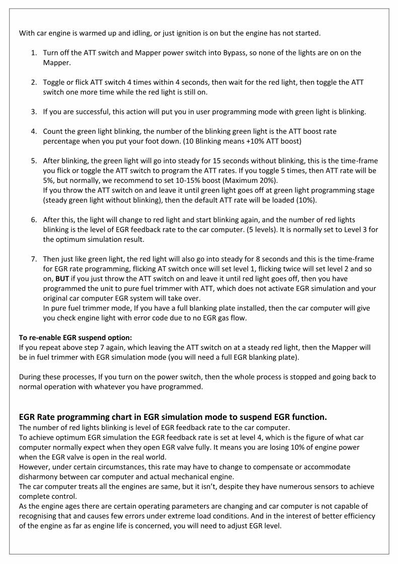
With car engine is warmed up and idling, or just ignition is on but the engine has not started.
1. Turn off the ATT switch and Mapper power switch into Bypass, so none of the lights are on on the Mapper.
2. Toggle or flick ATT switch 4 times within 4 seconds, then wait for the red light, then toggle the ATT switch one more time while the red light is still on.
3. If you are successful, this action will put you in user programming mode with green light is blinking.
4. Count the green light blinking, the number of the blinking green light is the ATT boost rate
percentage when you put your foot down. (10 Blinking means +10% ATT boost)
5. After blinking, the green light will go into steady for 15 seconds without blinking, this is the time-frame you flick or toggle the ATT switch to program the ATT rates. If you toggle 5 times, then ATT rate will be 5%, but normally, we recommend to set 10-15% boost (Maximum 20%). If you throw the ATT switch on and leave it until green light goes off at green light programming stage (steady green light without blinking), then the default ATT rate will be loaded (10%).
6. After this, the light will change to red light and start blinking again, and the number of red lights blinking is the level of EGR feedback rate to the car computer. (5 levels). It is normally set to Level 3 for the optimum simulation result.
7. Then just like green light, the red light will also go into steady for 8 seconds and this is the time-frame for EGR rate programming, flicking AT switch once will set level 1, flicking twice will set level 2 and so on, BUT if you just throw the ATT switch on and leave it until red light goes off, then you have programmed the unit to pure fuel trimmer with ATT, which does not activate EGR simulation and your original car computer EGR system will take over. In pure fuel trimmer mode, If you have a full blanking plate installed, then the car computer will give you check engine light with error code due to no EGR gas flow.
To re-enable EGR suspend option: If you repeat above step 7 again, which leaving the ATT switch on at a steady red light, then the Mapper will be in fuel trimmer with EGR simulation mode (you will need a full EGR blanking plate). During these processes, If you turn on the power switch, then the whole process is stopped and going back to normal operation with whatever you have programmed.
EGR Rate programming chart in EGR simulation mode to suspend EGR function. The number of red lights blinking is level of EGR feedback rate to the car computer. To achieve optimum EGR simulation the EGR feedback rate is set at level 4, which is the figure of what car computer normally expect when they open EGR valve fully. It means you are losing 10% of engine power when the EGR valve is open in the real world. However, under certain circumstances, this rate may have to change to compensate or accommodate disharmony between car computer and actual mechanical engine. The car computer treats all the engines are same, but it isn’t, despite they have numerous sensors to achieve complete control. As the engine ages there are certain operating parameters are changing and car computer is not capable of recognising that and causes few errors under extreme load conditions. And in the interest of better efficiency of the engine as far as engine life is concerned, you will need to adjust EGR level.
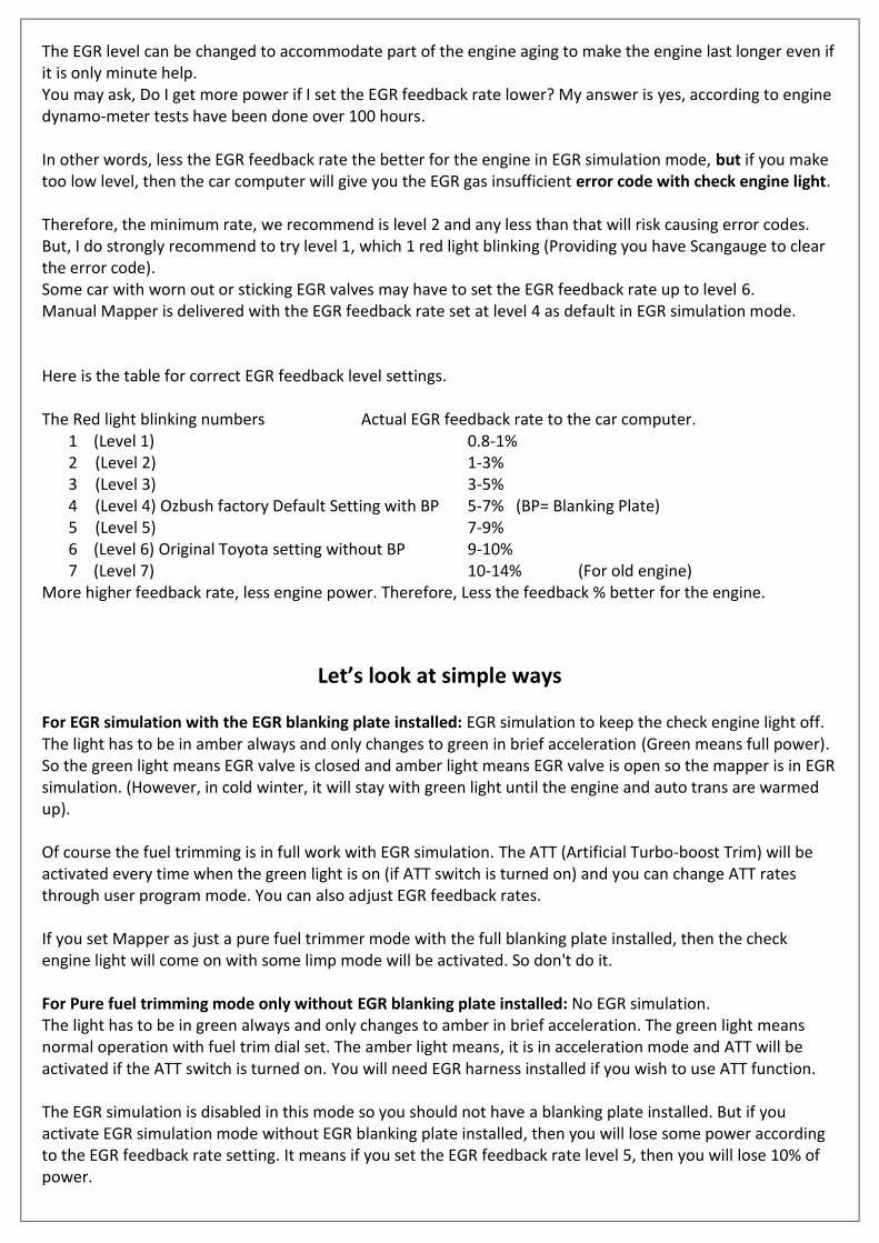
The EGR level can be changed to accommodate part of the engine aging to make the engine last longer even if it is only minute help. You may ask, Do I get more power if I set the EGR feedback rate lower? My answer is yes, according to engine dynamo-meter tests have been done over 100 hours. In other words, less the EGR feedback rate the better for the engine in EGR simulation mode, but if you make too low level, then the car computer will give you the EGR gas insufficient error code with check engine light. Therefore, the minimum rate, we recommend is level 2 and any less than that will risk causing error codes. But, I do strongly recommend to try level 1, which 1 red light blinking (Providing you have Scangauge to clear the error code). Some car with worn out or sticking EGR valves may have to set the EGR feedback rate up to level 6. Manual Mapper is delivered with the EGR feedback rate set at level 4 as default in EGR simulation mode. Here is the table for correct EGR feedback level settings. The Red light blinking numbers Actual EGR feedback rate to the car computer.
1 (Level 1) 0.8-1% 2 (Level 2) 1-3% 3 (Level 3) 3-5% 4 (Level 4) Ozbush factory Default Setting with BP 5-7% (BP= Blanking Plate) 5 (Level 5) 7-9% 6 (Level 6) Original Toyota setting without BP 9-10% 7 (Level 7) 10-14% (For old engine)
More higher feedback rate, less engine power. Therefore, Less the feedback % better for the engine.
Let’s look at simple ways
For EGR simulation with the EGR blanking plate installed: EGR simulation to keep the check engine light off. The light has to be in amber always and only changes to green in brief acceleration (Green means full power). So the green light means EGR valve is closed and amber light means EGR valve is open so the mapper is in EGR simulation. (However, in cold winter, it will stay with green light until the engine and auto trans are warmed up). Of course the fuel trimming is in full work with EGR simulation. The ATT (Artificial Turbo-boost Trim) will be activated every time when the green light is on (if ATT switch is turned on) and you can change ATT rates through user program mode. You can also adjust EGR feedback rates. If you set Mapper as just a pure fuel trimmer mode with the full blanking plate installed, then the check engine light will come on with some limp mode will be activated. So don't do it. For Pure fuel trimming mode only without EGR blanking plate installed: No EGR simulation. The light has to be in green always and only changes to amber in brief acceleration. The green light means normal operation with fuel trim dial set. The amber light means, it is in acceleration mode and ATT will be activated if the ATT switch is turned on. You will need EGR harness installed if you wish to use ATT function. The EGR simulation is disabled in this mode so you should not have a blanking plate installed. But if you activate EGR simulation mode without EGR blanking plate installed, then you will lose some power according to the EGR feedback rate setting. It means if you set the EGR feedback rate level 5, then you will lose 10% of power.
So please don't choose EGR simulation mode without the EGR blanking plate installed. Set the unit to the pure fuel trimmer mode in this case.
The Manual Mapper theory of operation The Manual Mapper has been designed to give more flexibility to the car user by trimming the air flow information to the car computer. Unlike many other power chip devices in the market, our manual mapper does not force more fuel into the cylinder without consent of the car computer. We believe the most of diesel engines in the market has already been tuned to maximum power from the factory and any more power extracting will seriously jeopardise the engine life. Our manual mapper will simply ask car computer permission by giving less or more air flow information. The car computer will accept total plus or minus 20% of error on mass air flow sensor input. For example, 1 PSI, which is one atmospheric pressure is turbo charged to 22 PSI then the car computer will try to maintain this 1:22 ratio most of time and it will accept 20% of the difference before error code is generated. To maintain constant turbo pressure, there is a controlling mechanism to adjust the turbo compression rate by turning vane disc to the turbine (it's called variable geometry). This mechanism is usually a vacuum operated lever or stepper motor to turn the vane disc. Therefore, if manual mapper reduces the air flow rate by say -10%, then the car computer will adjust the turbo pressure and also reducing the fuel injection accordingly. Likewise, if the manual mapper set dial to +10%, then the car computer will also adjust the turbo pressure and inject more fuel too. But this not the same as you are pushing the pedal to adjust speed or power. If you set the mapper dial to -15%, then you will find pedal response is very dull and you will struggle to climb on uphill. On the other hands, if you set the mapper dial to +10%, then uphill climbing response is very easier than without Manual Mapper installed. With this knowledge, manual mapper has trimmed range of -15% to +15%, which is a very conservative figure without pushing to the extreme end. Any more difference than 20%, the car computer will reject and generate error code with a check engine light on the dashboard. In many old car engines, the variable geometry vane disc in the turbocharger is seized up by constant heat and cannot rotate fully and causes the error condition in extreme cases. It is a quite common occurrence in Toyota 1KD-TV engines (P1251 error code). You will only find out when you buy up market power devices try to get some more power. Many people concerned about the over pressure problem when EGR pipe is fully blocked to stop EGR gas. Many worried what happens when you take your foot off the pedal and where those overcharged gasses will go? My answer is, it will dissipate through the turning cylinder. The cylinder is your turbo waste gate. Then they say wouldn’t it kill the engine with pre-detonation or stressing the engine parts? My answer is, how can a pure air can pre-detonate? When you take your foot off the pedal the fuel injection is stopped immediately and only pure air goes into the cylinder. And moreover, the pressure in the intake or cylinder is identical to the last burning pressure before you take your foot off the pedal. The air pressure is exactly same as the previous cycle when you were burning fuel. There is no special type of over air pressure condition is created. I must say they need to do some more study about diesel engine basics, in petrol engine yes, it can happen and you do need a waste gate to quickly relieve the pressure. When there is no fuel to burn in the cylinder, there is no danger whatsoever with only air. It will only do good thing like cooling the cylinder for the next combustion cycle for better efficiency.
Remember, when you accelerate to full power the EGR system is shut off by the car computer, the EGR pipe is blocked off by EGR valve and then the EGR valve is open again and remain open for emission control when the desired speed is achieved (decided by the car computer). The car computer also knows when and how much fuel will be injected. However, you will need to make sure the pressure difference between mass air flow (MAF) sensor and turbo boost (MAP) sensor must always be same compression constant ratio and must not deviate over 20% tolerance. ATT setting safety margins: Therefore, It is a very important that you should not create that condition in our Manual Mapper settings. For example, if you set the mapper dial at -10% for economy running and ATT (Artificial Turbo-boost Trim) setting is at +15%, then the total difference is now over 25% and this will cause the car computer to generate P0101 error code due to your setting is over 20% of tolerance (However, the error code is not always generated due to individual difference of the engine). P0101 error is the MAF sensor range and performance error. This error will put you into limp mode beware! In this case, your setting should be dialled at -5% and ATT setting +14%, so it will be total 19% tolerance with some safe margins. If you wish to run at the super economy mode, due to running out of fuel in the outback or whatever, then you should turn off the ATT then set the mapper dial at -15%. This setting will give you dull pedal response, but the car computer will try to give you the maximum mileage. I have had few experiences in the highway running out of fuel between fuel stations, I have seen some 5.5L/100km in moderate camping gear payload with mapper dial setting -15%. I got to the fuel station. Please note: We found ATT or EGR feedback settings are NOT same for every car. We have tried more than 20 Prado 150 and found ATT and EGR feedback settings were different for every car which they can accept without error. Therefore, I strongly recommend for you to try and find out settings for your car to make sure you can have reliable operation without error codes. You will need to carry a Scantool to clear the error codes to try out. Otherwise, if you are not sure then just leave factory default settings, ATT 10% and EGR level 3. Use fuel trim setting between -13% to 13%. Many customers found fuel trim dial -15% and ATT 5% was the most economical and don’t notice the car is struggling due to ATT 5% will give you initial push then go into the super economy mode -15% for cruising. For heavy towing customers: We recommend to turn off the ATT and just set fuel trim dial to +10%. I have seen a customer using ATT setting 10% and fuel trim 0% to tow his caravan. The fuel trim dial maximum +15% setting is not recommended without trial due to some car computers will reject and put up check engine light. So please try out before you commit any heavy towing. You must know your engine characteristic.
The effect of full blanking plate: The blanking plate will increase the engine power around 10-18kw in cruising. But many people cannot feel the increase of the power and kept the pedal in the same position. The end result is increased fuel consumption. Therefore, it is recommended to set Mapper dial around -5% to compensate the effect. Every engine is different, you need to experiment with your engine.
Emergency Fix: The Manual Mapper is designed and manufactured according to military specification up to 90%. However, any electronics equipment can fail, no matter how well designed, we even had a customer calling near desert asking for help because he accidentally smashed the switch in the Mapper unit with his spanner while he was fixing additional fuel filter. We have been helping stranded people unrelated our product too.
So here are some suggestions for you if you have a problem. 1… If you suspect Mapper has a problem then all you have to do is simply throw the power switch to “BYPASS”. In this position, the Mapper is out of the circuit all together and the problem should go away if there was a problem with Mapper. The associated error codes are P0101 or P0401. 2… If you still not sure then you can disconnect the Mapper physically and restored to the original connection, which only takes 1 minute. 3… The error code P0400 will come up with check engine light, even if you removed the Mapper because you still have the blanking plate installed, but this does not put the car into limp mode. You can still drive the car with full power as long as you like. (I know many people drive like this to save the engine from soot problem.) However, if you get P0101 error, then you have a faulty MAF sensor, the Mapper don’t have a problem. Because we deal with MAF sensor always, we found a surprising number of people have a MAF sensor problem regardless of the Mapper. Reminds you they do fail. So if you have a Manual Mapper problem, then all you have to do is to set the switch to bypass or physically disconnect it. You can still drive with error code P0401 (due to blanking plate). You do not need to remove the blanking plate. However, you will not know if there would be another problem cropping up because the check engine light is already on. Check the engine status with Scantool always to see if any other error codes are generated. You can still drive in limp mode even if you have a faulty MAF sensor (P0101 error code) to reach the nearest town to order the new MAF sensor. Emergency Field Master Reset for the car computer: To clear the check engine light and the error codes without Scantool. The scantool will clear any codes, but in case if you don’t own the scantools then this is a way to clear the error code and works most of the time. 1… Disconnect the Negative battery terminal to disconnect the power to the car computer. 2… Push on the brake pedal for two minutes to discharge any remaining charged power in the car wirings and devices. 3… Reconnect the battery terminal. This action should clear, the most of the codes but if you can’t then you are most likely to have a serious problem which turns on the check engine light straight away. Software Revision Notice: This manual is for revision V3.4 on. The difference of the old and new software is EGR rate settings. Before the V3.4 the EGR rate setting was up to Level 5 and default setting was 3. Otherwise functionally identical.
Disclaimer notice: Please take ample awareness about the Manual Mapper usage, we take as much research as possible to prevent any mishaps but the ultimate responsibility is on you. Please look after yourself and your car at best. Do not be distracted by your devices in the cabin. Look out on the road! We may not refund the unit in case of you have changed your mind because once you have installed the Mapper unit, then it is no longer re-saleable due to mechanical markings. The unit is resin sealed and can not be re-manufactured. Please always in communication with us for any difficulties or questions, we are not responsible for your action and consequent damages or costs. Please don’t hesitate to send any inquiries to [email protected]. We will try best to answer all we can.
Ozbush Electronics ©2017
www.ozbushelectronics.com.au
Email: [email protected]