anass 2007 - template - budapest university of … · web viewhorizontal reaction components of...
TRANSCRIPT

Horizontal reaction components of pointed vaults
Gábor Lengyel – Katalin Bagi (corresponding author)Department of Structural Mechanics
Budapest University of Technology and Economics1111 Budapest, Műegyetem rkp. 3. K.mf.63.
Abstract The magnitude of horizontal reactions under selfweight are analysed for pointed barrel vaults with different eccentricities. The magnitude is expressed as the function of the eccentricity (deviation of the pointed generator curve from the circle). Vaults with fixed supports and with increasing outwards support displacements are considered. An analytical model based on continuous Timoshenko beam theory is suggested for barrel vaults, and then checked with computer-simulated experiments. The results show that with increasing support separation, the horizontal reaction tends to a constant value when reaching the statically determinate state. After this, the horizontal reaction varies only because of the gradual modification of the geometry due to large support displacements.
Keywords 3DEC; masonry; pointed arc; geometry; support displacement
1 Introduction1.1 The analysed problemArches and vaults based on pointed generator curves are essential components of gothic architecture. Pointed structural shapes have preliminaries in Islamic architecture, and the idea may have been brought to the Christian Europe from Moorish Spain, or from the near East by the crusaders. The beauty of pointed shapes surely significantly contributed to the increasing popularity of this idea in cathedral art of the Christian world from the XIIth century, but without clear mechanical advantages such a rapid and wide spread would not have been possible. Pointed structures are known to express smaller lateral thrusts to their supports than circular vaults, which means that arches and vaults could be built higher and more slender, larger distances could be spanned over with shapes pointing towards the sky, and more light was allowed to enter through the large windows than ever in the constructions of the previous centuries. Pointed curves (which will serve below as generators for the vault shapes to be analysed) can most easily be produced with the help of circular arcs in the way shown in Figure 1: two arcs, having their radii R larger than half of the span L, and their centres O being located eccentrically (i.e. not coinciding with the middle of the span), intersect in a symmetrical manner. The larger is the radius of the arcs, the larger is the eccentricity (i.e. the deviation of the arc centre from the middle point of the span, quantified with the help of the scalar ) and the higher is the resulting pointed curve. Note that R = (0,5 + ) L which means that = 0 corresponds to the semicircular shape and = 0,5 belongs to the pointed arch based on the equilateral triangle. As long as the arc centre remains on the horizontal base line, the tangent is vertical at the two supports, but the generator curves become higher with increasing eccentricity.
Figure 1. The analysed pointed curves and thedefinition of the eccentricity parameter
1
O
R
L
L

This study focuses on the magnitude of lateral thrusts expressed on the supporting structural members (walls and pillars) by pointed barrel vaults. In the present study analytical investigations and discrete element simulations are performed, in order to assess how the magnitude of eccentricity influences the magnitude of horizontal thrust (normalized with the vertical reaction component, which is equal to the weight of the half of the structure). The analysed barrel vault is shown in Fig. 2. An analytical model based on the Timoshenko beam theory is developed, and the results are compared with DEM-simulated experimental results.
Figure 2.The analysed structure
The geometry of a vault is never perfect in reality. In addition to inevitable imperfections of the construction procedure, a primary reason is that displacements of the supports (particularly those caused by the forces expressed by the vault itself) lead to gradually increasing modifications of the vault shape and position. The dominant support displacement is usually the outwards translation of the underlying structural elements. In order to analyse this effect, during the computations the supports of the simulated vaults were gradually moved outwards in a quasi-static manner, and the horizontal reactions were recorded throughout the process. An important objective of the investigations was to see how the reactions varied before and after reaching the statically determinate state.
1.2 The applied methodsThe present paper compares analytical results on the horizontal reactions to the outcomes of numerical simulations. The two most important classes of analytical approaches to study the forces in masonry arches are Limit State Analysis and deformable continuum models. Being inspired by the classical works of Heyman (1966), (1969) etc. that were based on the idea of Kooharian (1952), several researchers applied Limit State Analysis to develop different techniques for the analysis of masonry arches. Following this approach, Romano and Ochsendorf (2010) focused on pointed masonry arches and analysed the effect of the deviation from circular shape, regarding minimum thickness, collapse loads, and the admissible domain of horizontal thrust. The authors determined the statically admissible range of the thrust through graphic statics, according to the Static Theorem of limit state analysis. Their results will be compared below to the outcomes of the present investigations. The investigations of De Rosa and Galizia (2007) were also based on the Static Theorem. Arches of different eccentricities (from semi-circular to pointed arch based on the equilateral triangle) were analysed under selfweight plus live load, and the highest possible live load multipliers were searched for. Their method took into consideration the frictional limit and the compression strength of the voussoirs (“yield domains” described the admissible relations between the different components of the contact forces and moment). Solving the optimization problem to maximize the load multiplier while satisfying the equilibrium conditions as well as the restrictions for contact forces and moments, it was found that the equilateral arch showed the best resistance to the live loads. It was also pointed out that sliding occurred only in case of small frictional resistance at the contacts (below 1733, depending on the arch shape). The application of deformable continuum models for masonry is perhaps less accepted in general, though the widely applied MEXE method for example is based on the elastic beam analysis of Pippard (1948). It was emphasized by Huerta (2001) citing the studies of Heyman that
2

the elastic solution (and particularly the internal force system) is rather sensitive to small disturbances of the geometry, e.g. to support displacements. In addition, if linearly elastic material behaviour is applied in the model, significant deviations can be expected from the real structural behaviour where the masonry can hardly resist tension. In spite of these doubts, a few authors took the challenge and applied continuous beam theories for masonry arches. The papers of Audenaert et al (2004), (2007) are excellent examples for this approach: the authors developed a linearly elastic – perfectly plastic – no-tension model in the frame of a classical beam bending approach. The discrete built-up of the masonry and the continuum-mechanical modelling approach are not necessarily in unresolvable contradiction. Finite element models can also be applied to study masonry arch behaviour, and the discrete nature of the masonry can be represented in different ways. Individual voussoirs and the mortar layers between them can be modelled, for instance, with 3D finite elements having different material properties for the mortar and for the blocks where contact elements represent the mortar-block interface. Hejazi and Jafari (2010) applied FEM this way to compare different bricklaying techniques, and analysed the stress distributions in the mortar and in the blocks. Alternatively, contact elements with suitable constitutive behaviour can also represent the joints. When such a detailed modelling is not necessary, homogenized continua can be defined, either as 1D beam models, or 2D shell or 3D body elements. The seeming contradiction between limit state analysis with rigid blocks, and micro-level continuum models where the blocks and the joints have finite resistance to different stress components, is partly resolved by the approach proposed by Foce and Sinopoli (2001), Foce and Aita (2003). The graphostatic method originally introduced by Durand-Claye (1867) searches for a range of admissible contact force systems that satisfy both the equilibrium conditions and the restrictions for compressive, tensional and frictional stresses in the joints. Using the method, Aita et al (2004) investigated the collapse modes (rotational and sliding) of pointed arches under selfweight, for different values of thickness and friction coefficients. The mechanical state (i.e. elastic, cracked for tension, crushed for compression) of points of arches having different circular, pointed or horizontally elongated ellipsoidal shapes were analysed in Aita et al (2009) and their load bearing capacity was compared. The higher load bearing of pointed arches was clearly shown.Continuous beam models are usually thought to be unreliable for masonry arches. To query this belief, in the present paper a continuous beam model (inspired by Oh et al, 1999) will be developed, and the range of validity of its predictions will be checked with DEM-simulated experiments.The computer simulations in the present study were done with 3DEC, a commercial discrete element code. The discrete element method (DEM) considers the structure to be a collection of separate blocks, “discrete elements”, each of which is able to move and – in most software – to deform independently of each other. The blocks may come into contact with each other hence distributed forces can be transmitted from one block to another, causing stresses and deformations in the blocks. They can slide along each other, be separated, or the contacts may be partially cracked. Because of its ability to follow the characteristic failure modes and collapse histories of masonry structures in detail, DEM can serve as a tool to check theoretical results with the help of computer-simulated experiments. A characteristic application of DEM can be found in Rizzi et al (2014): a discrete element code was used for the comparison of the theoretical predictions for circular arches by Milankovitch (1907), Heyman (1969) and Cochetti et al (2011).In that version of the 3DEC code which is applied in the present study the discrete elements are made deformable by being subdivided into uniform-strain tetrahedra whose nodal translations are the basic unknowns of the analysis. The discrete elements in 3DEC may have any polyhedral shape. The displacements of the nodes of the tetrahedra are to be calculated from Newton’s force-acceleration law. In the equations of motion the mass of a gridpoint is defined as the volume of the Voronoi-cell around that gridpoint multiplied with the material density of the element. Different forces acting on the Voronoi-cell like selfweight, drag force, distributed forces from neighbouring Voronoi cells inside the same discrete element, and contact forces expressed by the neighbouring discrete elements are reduced to the gridpoint. The joints between the elements may have, in principle, two different roles in DEM, depending on the problem to be modelled. The first option is that the joints represent some kind of mortar layer having a finite thickness in reality. In this case, the material parameters of the joints express
3

the deformability of these layers and their failure criteria. Therefore a normal and a tangential stiffness (i.e., resistance to relative translation) have to be prescribed along with fracture criteria (normal and shear strength) and perhaps a friction coefficient in order to define the conditions when the joints fail.The other option (the one used in the present study) is most suitable if there is no material layer modelled between the blocks in the real system. In this case the aim is to simulate dry contacts, or perhaps to neglect the weak mortar in an old masonry structure. The friction coefficient of the joints still has a real physical meaning, expressing the sliding criterion of the two contacting bricks or stone blocks along each other. A normal and a shear stiffness express the resistance to relative displacements of contacting material points in the contacts: the increments of the forces transmitted from one block to the other are the product of the increment of the relative normal or tangential translation of the two material points, and of the normal or shear stiffness. These contact stiffnesses are, in this case, artificial numerical penalty parameters only.The equations of motion are solved (the displacement increments of the nodes during consecutive finite t time intervals are determined) using a central difference scheme for numerical time integration. From the displacement increments done during a timestep the strain increments, changes of stresses and forces, etc. are then calculated: the simulation of the state changing is achieved by step-by-step calculation of the incremental motions of the gridpoints.Technical details of the applied 3DEC code are described in several papers, books and manuals, e.g. in Lemos (2016), Lengyel and Bagi (2015) or Szakaly et al (2016). The paper is organized as follows. Section 2 focuses on deriving theoretical predictions for the horizontal reaction of barrel vaults, treating them as continuous, two-dimensional structures (so a unit slice of the vault is considered), assuming that the analysed slice is in plane stress state. The derivations are then checked with the help of 3DEC simulations in Section 3, where the plane stress and the plane strain behaviour are also compared. Finally, in Section 4 the most important conclusions are drawn.
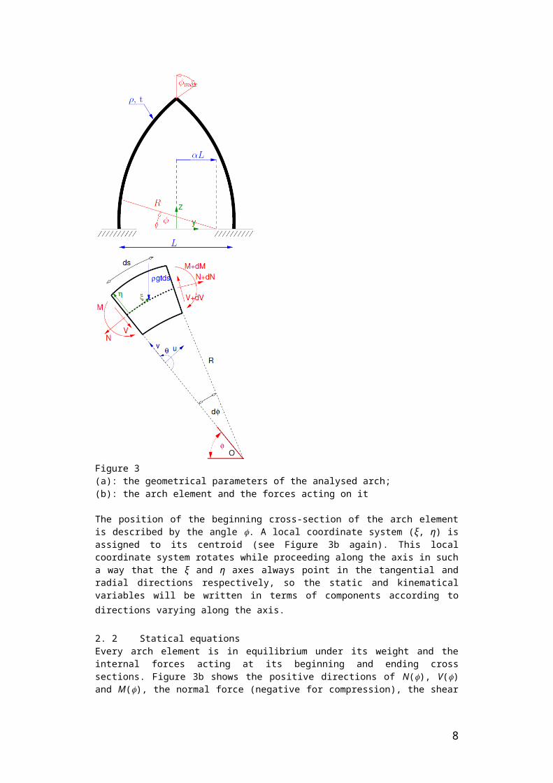
2 Theoretical analysis of the horizontal reaction of pointed barrel vaults2.1 Basic assumptions and notationsThe middle surface of the analysed pointed barrel vault is cylindrical, produced by two intersecting circular arcs which serve as the generator curve of the middle surface (see Figure 3a). Consider a unit thickness slice of the barrel vault with thickness t and material density ; this slice is modelled as a Timoshenko beam with curved axis (Henrych, 1981; Borg, 1959). The calculations are based on the following assumptions: The material of the arch is linearly elastic, and it resists arbitrary tension as well as compression and shear. (This assumption contradicts real masonry behaviour so its consequences will be analysed with the help of comparing the theoretical predictions to discrete element simulation results.) The translations and rotations are small. (Analysed support displacements will not exceed 0.03 % of the span, which corresponds to 3 mm for a 10 m span.) The arch is represented with its axis defined as the curve in the half of the thickness. The basis of the derivations will be the behaviour of an infinitesimally short arch element shown in Figure 3b, whose length ds is measured along the axis. (The mass centre of the arch element is located slightly outside the axis, but this deviation will be neglected.) According to the Timoshenko beam theory, the material points that form planar cross-sections being originally perpendicular to the axis of the beam will remain planar, though not necessarily perpendicular to the deformed axis.
4

Figure 3(a): the geometrical parameters of the analysed arch; (b): the arch element and the forces acting on it
The position of the beginning cross-section of the arch element is described by the angle . A local coordinate system (ξ, η) is assigned to its centroid (see Figure 3b again). This local coordinate system rotates while proceeding along the axis in such a way that the ξ and η axes always point in the tangential and radial directions respectively, so the static and kinematical variables will be written in terms of components according to directions varying along the axis.
2. 2 Statical equationsEvery arch element is in equilibrium under its weight and the internal forces acting at its beginning and ending cross sections. Figure 3b shows the positive directions of N(), V() and M(), the normal force (negative for compression), the shear force and the bending moment at respectively The equilibrium of the arch element can be expressed by the following three equations:
(1)
Since the angle d is small (cos (d) 1 and sin (d) d), hence after some rearrangements the three equations can be written as
(2)
These equations are, in principle, identical to those in Audenaert et al (2004), (2007).
2. 3 Kinematical equations
5

Three displacement variables will be used to characterise the kinematics of a cross-section at (see Figure 3b again). The translations u() and v() denote the tangential and radial translation components of the centroid of the cross-section, while () expresses the rotation of the material region forming the cross-section which is perpendicular to the axis in the initial state.(a) (b)
Figure 4.Calculation of the rotation of the axis in a curved element, (a) the translations of the axis; the rotation components of the cross section
In case of the Timoshenko theory the rotation () of the planar material region forming the cross-section is not equal to the rotation of the axis, (). Instead, () is the combined result of two effects: (1) as the planar set of material points forming the cross-section rotates while the arch element has zero shear deformation, the rotation of the material region is equal to (); and (2) the shear deformation () of the arch element (without any rotation of the axis) leads to the rotation of the material region equal to (). The rotation of the material region forming the cross section is () = () (). The rotation of the axis, i.e. () = () + (), can alternatively be expressed in terms of the translation components of the centroids at and at +d , taking into account that the angle d is small and that ds = R d (see Figure 4):
(3)
or equivalently: (4)
From the kinematic variables above, the deformations of the arch element, i.e. the elongation (), the shear deformation () and the curvature () have to be derived with the help of the derivatives with respect to the length parameter of the arch element, ds. These deformations of the arch element will be expressed now in terms of the relative displacements of the cross-sections at and at +d.First, the elongation of the axis is
(5a)
or . (5b)
Second, the shear deformation of the arch element, () = () (), can also be expressed in terms of the basic kinematical variables:
. (6)Finally, the normalised relative rotation of the cross-sections at and at +d:
6

. (7)
The constitutive equations will relate these three characteristics to the internal forces.
2. 4 Constitutive equationsAccording to Borg and Gennaro (1959), in a curved beam with small thickness the internal forces N(), V() and M() can be related to the deformations (), () and () in the following way:
; ; . (8)
Here E and G denote the Young‘s modulus and the shear modulus of the material of the arch. The Timoshenko shear coefficient k is chosen to 5/6 because of having a rectangular cross section. The geometrical characteristics I and A (inertia and area of the cross-section) are assumed to be constant along the arch, which means that the possibility of partial cracking or complete hinging of the cross-sections is excluded from the analysis. (Note that the Bresse-equations applied in Audenaert et al (2007) do not contain the effect of shear deformations, but on the other hand, in those papers a sophisticated elasto-plastic no-tension model is used for the behaviour of the cross-sections.)In a statically indeterminate structure the results may, in general, strongly be influenced by the actual material properties. In every calculation throughout the paper the Young‘s modulus E = 14.8 GPa, Poisson‘s ratio = 0.20 and material a density = 2348 kg/m3 (travertine limestone) were applied. In addition, a sensitivity test will also be presented below in Section 2. 6 to see how the material properties influence the statical behaviour.
2. 5 Boundary conditionsThe mechanical model of the half of the pointed arch is shown in Figure 5 and the boundary conditions are listed in Table 1 (dy and Rz denote horizontal outwards translation and vertical internal force component, respectively):
Figure 5.Boundaries of the half arch
Table 1.Boundary conditions of the half arch
Because of the symmetry of the problem, at the top of the arch the resultant of N(max) and V(max) should be horizontal; a statical boundary condition is received this way. Five kinematic boundary conditions can also be specified. The bottom left cross section of the arch remains horizontal and does not move vertically; its horizontal translation is zero or a prescribed value d. The top cross-section cannot rotate, neither translate horizontally, because of the symmetry of the problem again. (Note that these conditions exclude the occurrence of cracks at the support or the crown in the masonry.) The six boundary conditions can be written in terms of the statical and kinematical variables in the following way:
7
(9)
2. 6 Solution and the results
After substituting the kinematical (5b), (6) and (7) into the constitutive equations (8), three first-order differential equations are received, while the statical equations (2) are also three first-order differential equations. A system of six first-order differential equations is received, where the unknowns are the displacements, rotations, and internal forces (10):
(10)This system can be written in the form . The complete solution of this system consists of a homogeneous and a particular part: . The homogeneous system has six linearly independent solutions . A 66 matrix can be defined which consists of these six solution vectors:
(11)(Note that bold capitals denote matrices, so that X is a matrix whose columns are the six independent xi vectors.) The solution is the linear combination of the xi() vectors, so
. This system can be solved according to Arnold (1973), Tüfekci and Arpaci
(1998). The eigenvalues of the matrix A are: (i is the imaginary unit), so three duplicities in the eigenvalues are received. The unknown matrix X() can be written in the following form:
(12)where H1, H2, … H6 are the Hermitian matrix polynomials of matrix A and can be determined in the following way. Introduce the auxiliary complex variable, z. Every Hj should satisfy
, where
, and . The
coefficients αj0 , αj1 , … αj5 belonging to Hj are searched for, separately for every j. These coefficients can be calculated from the linear equation system (13) where the actual values z = i, z = 0 and z = i are the eigenvalues of matrix A:
8

. (13)
On the right side the j-th unit vector can be seen: for , for
and so on. In order to derive the particular part, the method of undetermined coefficients can be applied, where . The vector is a function of position along the arch, ϕ . By
substituting this expression into , the following relation is received:
(14)But matrix solves the homogeneous equation, so .
Consequently, , which yields the particular solution:
(15)Finally, the complete solution is the sum of the homogeneous and the particular part:
As mentioned above the homogeneous solution is the linear combination of the solution vectors. The unknown vector c (remember that ) has six scalar components, that have to be determined with the help of the six boundary conditions, see Eq. (9), as follows: The six boundary conditions set requirements for the five functions u(), v(), (), N() and V(). These are components of x() so they can be written as:
(note that the scalar function M() is not listed here, since no boundary condition is specified for the bending moment). Since the x1(), x2(), … x6() components of the homogeneous part and the xp() particular part are already determined, the only unknowns on the right side are the c1, c2, … c6 coefficients.The six boundary conditions can be collected into a linear equation system Mc +b = 0 where:
9

and
.
Now the unknown c can easily be determined from c = M-1 b . The results will be visualized and illustrated in the rest of Section 2.6.
Figure 6Reaction components acting on the bottom boundary
Now the results on two statical characteristics will be shown here. The first quantity (denoted by , named the normalized horizontal reaction), is the magnitude of the horizontal force component (see Figure 6), divided with the magnitude of the vertical component (i.e. with the weight of the half arch, shown in Figure 5):
.This quantity was determined for different eccentricities, thicknesses, and for different magnitudes of the horizontal support displacement d. The second quantity (e, the eccentricity of the compression force) can be different in every cross-section:
.This quantity expresses whether the whole cross-section is under compression: for e < -100% or for e > 100% the resultant of the normal stresses is outside the kernel of the cross-section, which means that tension occurs at a part of the cross-section according to the applied theoretical model, and in case of a no-tension material cracks should appear.Regarding the normalized horizontal reaction, first a sensitivity study was performed to clarify whether the material properties of the vaults make any influence on .
10

Figure 7Normalized horizontal reaction for different material parameters
The reactions were determined for circular arches having the same geometry with t = 0.08 L , using different Poisson’s ratios (from 0 to 0.5) and Young’s moduli (ranging over several orders of magnitude). The colour scale in Figure 7 indicates the corresponding values of . Obviously, the normalized horizontal reaction was practically independent of and E. Indeed, though the analysed arch model is statically indeterminate, since the material parameters were always constant along the arch in every case and the geometry was also the same, it was found that the equilibrium was maintained with the same direction and position of the reactions. After this test, all further calculations were based on properties of travertine limestone given in Section 2. 4.
Figure 8Normalized horizontal reaction as afunction of the eccentricity of the vaultshape, for selfweight with fixed support (d = 0), for t = 0.08L
Figure 8 shows how the normalized horizontal reaction depends on the shape of the arch. The calculations were done for the arch thickness t = 0.08 L. Proceeding leftwards along the horizontal axis the arch shape becomes more and more strongly pointed. According to the Timoshenko beam model, the horizontal reaction significantly decreases with increasing pointedness : it drops by about 45% when reaching the arch shape based on the equilateral triangle ( = 0.5); and by 55% in the case of = 1.0, if compared to the horizontal reaction of the circular arch ( = 0).
(a) (b)
Figure 9Normalized horizontal reaction, (a): as a function of the eccentricity of the arch, for different thicknesses; (b): as a function of the thickness of the arch, for different eccentricity parameters
Figure 9 also belongs to fixed supports. Arches having different thicknesses were analysed under selfweight. Similarly to Figure 8, it was found that pointed arches have smaller normalized horizontal reactions, and the increasing thickness of the arch make the direction of the resultant reaction more vertical.
11

The next diagram, Figure 10, focuses on the effect of outwards support displacements of arches with the same thickness, t = 0.08 L. The analytical derivation predicts that the increase of the support translation causes the horizontal reaction to decrease monotonically. Figure 10 shows a linear dependence of the normalized horizontal force on the magnitude of the displacement d, for every analysed arch shapes. For the circular arch ( = 0) the force decreases to zero and then turns to outwards direction already at around d/L = 0.017%, which corresponds to 1.7 mm for a 10 m span. Indeed, Figure 10 confirms that the elastic solution for the forces is very sensitive to the support displacements.
Figure 10Normalized horizontal reaction for different support displacements
Larger causes a slower decrease of the horizontal reaction with the support displacement, but the tendency is the same. Note that a negative means that since the horizontal reaction is directed outwards, significant tensioned zones exist in the vault. This is in contrast to real masonry behaviour, so the tension-resisting theoretical model cannot suitably reflect the horizontal reactions for circular or only slightly pointed shapes with even very small support displacements. The theory loses its validity for smaller displacement values in case of circular or slightly pointed arches than in case of strongly pointed shapes. The issue will be analysed now in more detail with the help of the eccentricity of the compression forces.The diagrams in Figure 11 illustrate how the e eccentricity of the compression force varies along the length of the arch submitted to its selfweight, without support displacements. (Note that going rightwards along the horizontal axis means proceeding upwards along the axis of the arch.) Solid lines belong to thin arches (t = 0.08 L); dotted lines correspond to thick arches (t = 0.20 L). According to the theoretical model, tension occurs within those cross-sections where the value of e falls outside the interval (100%; +100%). The diagrams show that strongly pointed arches and thick arches are, in general, more favourable: the eccentricities are smaller at most cross-sections. The neighbourhood of the crown carries large bending moments in all shapes, particularly in the case of small thickness. From among the three shapes (circular; pointed based on equilateral triangle; pointed with = 1.0) the arch based on an equilateral triangle is the most advantageous from the point of view of the eccentricity of the normal forces. Interesting to note that in case of the thick vaults the reactions act inside the kernel (e is smaller than 100%) for the circular as well as for the pointed shape. The four curves in Figure 12 belong to four different magnitudes of support displacement (red curve for fixed support). All diagrams were calculated for an arch with t /L= 0.08 (thin arch) and =0.0 (circular arch). The continuous beam model predicts that the eccentricity becomes very large around the crown already for the slightest displacement: d/L = 0.03 % means 3 mm translation for a 10 m span, which is in the range of construction errors.
12
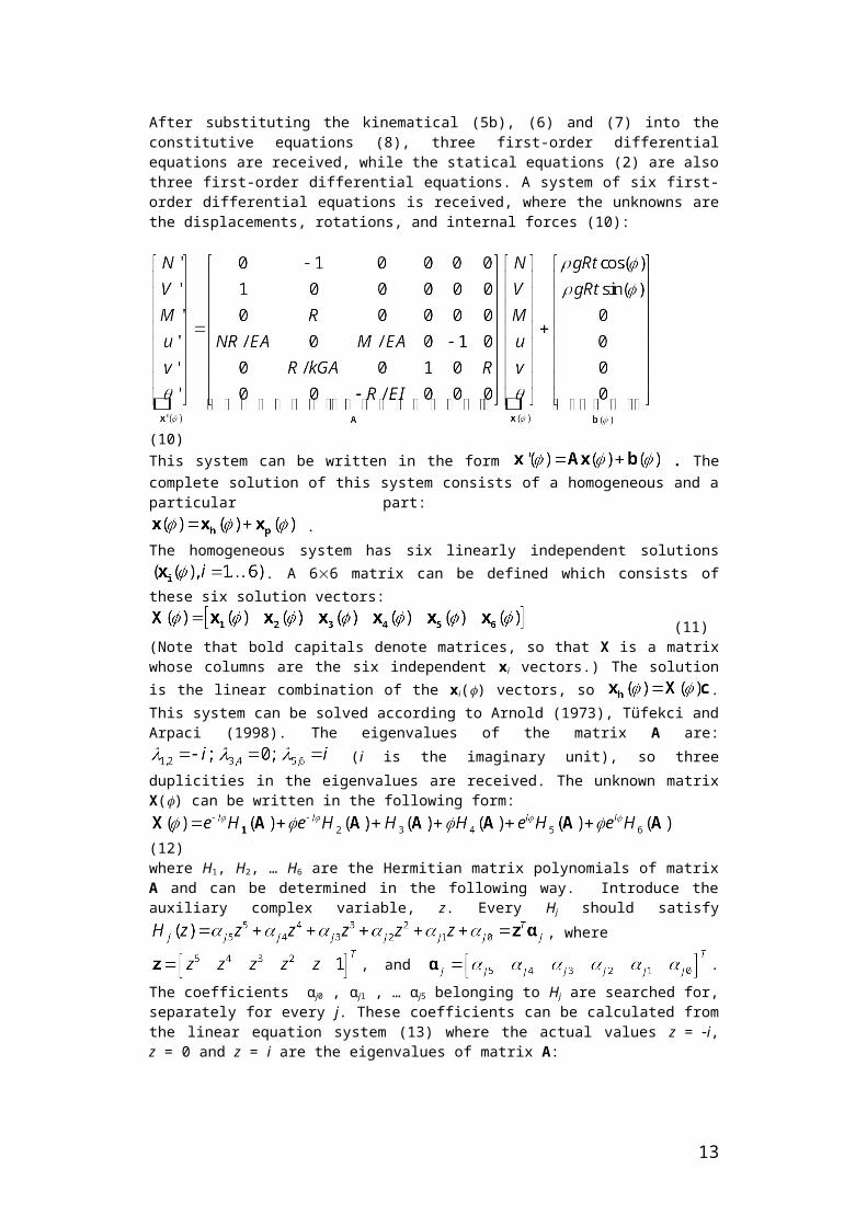
Figure 11 Figure 12Eccentricity of compression, for selfweight Eccentricity of compression, for
increasing support displacement
At first sight these results seem to suggest that the theoretical model is reliable only for fixed supports and thick structures. However, it will turn out from the discrete element simulation results in Section 3 that though the support displacements indeed make the continuous model unreliable, the arch thickness does not have an appreciable influence on the validity of the theoretical prediction of the reactions.
3 Discrete element analysis of the horizontal reaction of pointed barrel vaults
3.1 Geometrical and material parameters3DEC models of barrel vaults of different eccentricities were prepared to have the same reference surface with a span L = 10 m. The shell thickness was 60, 80 or 100 cm in the different models (t = 0.06 L, 0.08 L and 0.10 L). The longitudinal length of the analysed barrel slice was equal to the quarter of the thickness. The contacts between the bricks were planar and perpendicular to the (y, z) plane (see Figure 13) and to the generator curve.
(a) (b) (c)
Figure 133DEC model of barrel vaults: (a) the blocks of the analysed slice, (b): nodes on both faces (front and back) are supported against translation in the x direction, in order to produce plane strain state; (c): nodes only on the front face are supported in the x direction, to allow plane stress state
The trapezoid-shaped discrete elements were made deformable by subdividing them into tetrahedral uniform-strain finite elements. The finite element mesh density was approximately the
13

same everywhere, with the maximal edge size of the tetrahedra equal to one quarter of the thickness of the masonry shell.The blocks were linearly elastic, isotropic in the 3DEC model, with infinite resistance to tension, compression and shear. Material parameters corresponding to travertine limestone were applied again, with those data given in Section 2. 4. The joints between the blocks were considered to be dry so that there was no resistance against tension in the contacts, and the friction angle was set to 40 or 30 in the different tests. Based on the analysis in Simon and Bagi (2015), the normal and tangential stiffness of the joints was set to 103 GPa/m.
3.2 Boundaries and the applied loadsTable 2 summarizes the boundary conditions applied in the 3DEC simulations. While the analysed arch was in a plane stress state in the theoretical model, in the DEM simulations plane stress and plane strain states were both simulated, in order to see the difference. Considering a long barrel, plane stress state may be a good approximation towards the ends of the structure if ends of the barrel are not sufficiently supported in the longitudinal direction. Plane strain state may characterise the middle region of the barrel where the neighbourhood of the analysed slice does not allow for longitudinal translations and consequently, longitudinal strains are equal to zero. The plane strain state was achieved in the simulations by fixing all the nodes against longitudinal translations along both faces of the slice (see the dark dots in Figure 13a). To get a plane stress state, only the front face was supported (Figure 13b). Regarding the in-plane behaviour of the analysed arch (see Figure 5 again), the vaults were imagined to be supported by two longitudinal walls under the barrel whose contacts with the blocks of the barrel resisted no tension but arbitrarily high frictional force (the degree of friction was set to 90). This was achieved by allowing arbitrary upwards (but no downwards) vertical displacements and prescribed outwards displacements in the bottom nodes of the lowest block of the arch (these nodes formed the 0b boundary). Consequently, hinging and separation was possible between the barrel and the imagined supporting wall, but sliding could not occur. The sym boundary (neighbourhood of the crown) was defined in the way shown in Figure 13a: the top block represented the half of the crown stone, and the nodes located on the axis of symmetry were fixed against y-directional translation.
Table 2.Boundary conditions in the 3DEC simulation of barrel vaults
3.3 Simulation results for fixed supports, selfweight onlySeveral arch geometries were analysed under selfweight with no displacements of the supports. After equilibrating the vaults, the reaction components and the internal forces could be recorded and then analysed. In general, a surprisingly good agreement was found between the analytical solutions and the discrete element simulations, in spite of the fact that significant regions of the discrete systems were partially cracked.Figure 14 compares the analytical prediction given by the continuous Timoshenko beam to the discrete element simulation results for the plane stress state and also for the plane strain state. The diagram shows the normalized horizontal reaction as a function of the geometrical eccentricity parameter , for 40 friction angle and arch thickness t = 0.08 L (a relatively thin arch). Though it was clearly shown in Section 2.6 (Figure 11) that significant regions carry tension according to the continuous model, the comparison with DEM brought an unexpected finding: the discrete element results practically perfectly coincide with the theoretical predictions. Consequently, the presence of the cracks in the discrete model does not cause a considerable difference in the distribution of internal forces from those internal forces that were predicted by the continuous model. This statement is checked in Figure 15 with the help of the eccentricity parameter of the compression forces. The value of e is shown along the length of the arch, for = 0 (circular shape) and = 0.5 (pointed arch based on the equilateral triangle). Solid lines represent the discrete element simulations and dotted lines denote the analytical predictions. Indeed, the results on the position of the compression force show a very close
14

coincidence between the cracked discrete systems and the continuous beams, even at those regions where the eccentricity of the force is large.
Figure 14. Figure 15.Comparision of the analytical and DEM Eccentricity of the compression results on the normalized horizontal along the arch: analytical and DEM reaction (t = 0.08 L) results (t = 0.08 L; plane stress state)
This surprisingly good agreement remains valid for other arch thicknesses and friction coefficients. Very low frictional resistance (30) and different thicknesses (t = 0.06 L; 0.08 L and 0.10 L) were tested, for plane stress and for plane strain as well. The results on the horizontal reaction were practically identical (see Figure 16).
Figure 16.Normalized horizontal reaction for different arch thicknesses and frictional resistance in the contacts, (a): plane stress state, (b): plane strain state
These normalized horizontal reactions can be compared to those minimal and maximal admissible values found by Romano and Ochsendorf (2010) with the help of Limit State Analysis. For arches with t/L = 0.15 the horizontal thrust was found by them to vary between the minimal value 0.24 … 0.14 times the half of the weight, depending on the shape of the arch (the first value corresponds to the semicircular arch, = 0 according to the notations of the present paper, while the second value corresponds to the arch based on the equilateral triangle, = 1). The maximal value in Romano and Ochsendorf (2010) was 0.58 … 0.3 times the half weight, depending again on the eccentricity of the arch shape. Figure 16 shows that the results of the discrete element simulations and the analytical solution given in the present study vary from 0.4 to 0.18, so they are in the interior of the admissible domain found by Romano and Ochsendorf (2010).
3.4 Simulation results for support displacementsThe arches already equilibrated for selfweight were then submitted to slow support displacements. A quasi-static support displacement procedure was produced by applying prescribed velocity histories on the 0b boundary. The displacement was produced in 1 mm steps.
15

In each step the initial velocity was set to 0.0054 m/s, and then gradually decreased until reaching the 1mm displacement, after which the system was stopped and balanced (until the equilibrium error dropped below 10-5). This loading process was the result of a rather lengthy experimenting with different values of velocities and displacement step lengths, and these parameters gave the shortest computation times while keeping the structure always close to equilibrium throughout the whole process (the ratio of largest unbalanced force magnitude versus average applied force magnitude always remained under 1%) The reactions and internal forces were determined in the equilibrium state. A characteristic result is shown in Figure 17: with increasing displacements, the horizontal force was decreasing first, and then at a definite displacement value (about 0.04 % of the span, depending on the exact vault shape) it reached a steady magnitude which remained constant for further small displacements. (Obviously, the initially statically indeterminate arch became determinate at this stage of the displacement process, because of crack opening producing internal hinges.) The magnitude of this constant value of the normalized horizontal reaction will be termed the residual horizontal reaction. (Note that this aspect of the behaviour is already impossible to reflect with the help of the applied continuous analytical model: as previously illustrated by Figure 12, the compression eccentricities become huge for much smaller displacements.)
(a) (b)Figure 17.Normalized horizontal reaction for support displacements in the DEM model (t = 0.08 L; friction angle 40), (a): range of small displacements; (b): range of large displacements
The residual reaction is shown in Figure 18, for plane strain and plane stress state respectively. The curves in different colours belong to different arch thicknesses and friction coefficients. The thick black line represents the normalized horizontal reaction predicted by the analytical solution for selfweight, for t = 0.08 L.
(a) (b)Figure 18. The magnitude of normalized residual horizontal reaction for different arch geometries, (a): plane strain state; (b): plane stress state. Black line represents the analytical prediction for plane stress state, for fixed supports, t = 0.08 L
16

The residual reaction is, in general, slightly smaller in the case of plane strain state (i.e. the middle region of a long aisle vault) than in plane stress state. The friction coefficient does not considerably affect the residual reaction, but the thickness of the arch is important: arches with smaller thickness express a larger normalized horizontal reaction on the supporting structural members below. The residual thrust values can also be compared to those found by Romano and Ochsendorf (2010) with the help of Limit State Analysis. As already mentioned above, they found that for arches with t/L = 0.15 the horizontal thrust should be between the minimal value 0.24 … 0.14 times the half of the weight, and the maximal value 0.58 … 0.3 times the half weight, depending on the eccentricity parameter of the arch shape. (Remember that the first value always belongs to the semicircular arch, = 0, while the other value corresponds to the arch based on the equilateral triangle, = 1.) That thickness, t/L = 0.15, for which detailed comparable data were available, was bigger than even the largest thickness for which discrete element simulations were done in the present study, t/L = 0.10. The DEM simulations gave that for the thinnest arch, t = 0.06 L, the horizontal thrust was 0.4 … 0.23, very close to the analytical Timoshenko prediction. With increasing thickness, the normalized horizontal residual thrusts decreased, and approached towards the minimal normalized horizontal thrust predicted by the Limit State Analysis: for t = 0.10 L DEM gave 0.3 … 0.17.To summarize, the analytical solution gives an upper boundary to the values of res: note that the smallest analysed thickness, t = 0.06 L, is close to Heyman’s minimal wall thickness for the circular arch (Heyman 2009, Makris and Alexakis 2013). So it can be concluded that the continuum-based analytical solution gives a safe (but not economic) estimation of the horizontal reactions, not only for fixed supports but also for small support displacements. The simulations could have been continued until failure in order to get an insight to the variation of the horizontal force, but the huge computational times (i.e. months) did not allow for such an analysis.
4 ConclusionsVaults with pointed arches, in general, express smaller horizontal thrusts on their supports than vaults with circular or only slightly pointed arches. The horizontal reaction components of barrel vaults with fixed supports can reliably be predicted with the help of the proposed linearly elastic continuous beam model, in spite that the model does not take into account the possibility of cracking. This statement holds only for the case of no displacements at the supports.In the case of increasing outwards support displacements the barrel vaults reach a state when they abruptly become statically determinate, and after this the reactions remain practically constant for further small increase of the displacements (a residual horizontal reaction magnitude can be assigned to the barrel vaults). Then the increasing displacements modify the geometry of the vault so significantly that the horizontal reactions increase again, until failure. In the range of small displacements the continuous model gives a good approximation of the residual reaction for thin structures, and a safe but not economic approximation for vaults with large thickness.
AcknowledgementsThe authors express their gratitude to the ITASCA Education Partnership Program for providing a copy of the 3DEC software to assist the above research. Financial support of the OTKA 100770 project is gratefully acknowledged.
References[1] Aita, D, Barsott, R, Bennati, S, Foce, F (2004): The statics of pointed masonry arches
between ‘limit’ and ‘elastic’ analysis, In: P. Roca and C. Molins (eds): Arch Bridges IV, CIMNE, Barcelona, pp. 353-362
[2] Aita, D, Barsotti, R, Bennati, S. (2009): Load bearing capacity of circular, pointed and elliptical masonry arches. In: Procs. XIX Congresso AIMETA, 14-17 Sept 2009
17

[3] Aita, D, Barsott, R, Bennati, S (2015): Some explicit solutions for nonlinear elastic depressed masonry arches loaded to collapse. In: Procs. XXII Congresso AIMETA, 14-17 Sept 2015, Genova, pp. 354-359
[4] Alexakis, H, Makris, N. (2013): Minimum thickness of elliptical masonry arches. Acta Mechanica 224, pp. 2977-2991
[5] Arnold, V.I. (1973): Ordinary Differential Equations, MIT Press[6] Audenaert, A, Peremans, H, De Wilde, W.P. (2004): Static determination of the internal
forces and displacements in arch bridges. TMS (The Masonry Society) Journal, 22(1), pp. 97-109
[7] Audenaert, A, Peremans, H, Reniers, G. (2007): An analytical model to determine the ultimate load on masonry arch bridges. Journal of Engineering Mathematics 59, pp. 323-336
[8] Borg, S, Gennaro, J. (1959): Advanced Structural Analysis. Van Nostrand, New Jersey[9] De Rosa, E, Galizia, F. (2007): Evaluation of safety of pointed masonry arches through the
Static Theorem of Limit Analysis. In: Procs. Arch’07, 5th International Conference on Arch Bridges, Madeira, Portugal, pp. 659-668
[10] Cochetti, G, Colasante, G, Rizzi, E. (2011): On the analysis of minimum thickness in circular masonry arches. Applied Mechanics Reviews, ASME, 64(5), #051002 (27 pages)
[11] Coccia, S, Di Carlo, F, Rinaldi, Z. (2015): Collapse displacements for a mechanism of spreading-induced supports in a masonry arch. Int. J. Adv. Struct. Eng. 7, pp. 307-320
[12] Durand-Claye, A. (1867): Note sur la vérification de la stabilité des voutes en maconnerie et sur l’emploi des courbes de pression. Ann. des Ponts et Chaussées 13, pp. 63-93
[13] Foce, F, Sinopoli, A. (2001): Stability and strength of materials for static analysis of masonry arches: Durand-Claye’s method. In: C. Abdunur (ed.), Arch 01, 3rd International Conference on Arch Bridges, Presses de l’École Nationale des Ponts et Chaussées, 2001 Paris, pp. 437-443
[14] Foce, F, Aita, D. (2003): Betwen limit and elastic analysis. A critical re-examination of Durand-Claye’s method. In: S. Huerta (ed): Procs. First International Congress on Construction History, Inst. Juan de Herrera, 20-24 Jan 2003 Madrid, Vol. II, pp. 895-905
[15] Hejazi, M, Jafari, F. (2010): Structural effects of brick arrangement and span length on mid-pointed arches. Advanced Materials Research 133-134, pp. 411-416
[16] Henrych, J. (1981): The Dynamics of Arches and Frames. Elsevier, Amsterdam[17] Heyman, J. (1966): The Stone Skeleton. International Journal of Solids and Structures, 2,
pp. 249-279[18] Heyman, J. (1969): The safety of masonry arches. International Journal of Mechanical
Sciences 11(4), pp. 363-385[19] Heyman, J. (1982): The Masonry Arch. Ellis Horwood Ltd, Chichester, UK[20] Huerta, H. (2001): Mechanics of masonry vaults: The equilibrium approach. In: Historical
Constructions, eds. P.B.Lourenco and P.Roca, Guimares, 2001, pp. 47-69[21] Lemos, J.V. (2016): The basis for masonry analysis with UDEC and 3DEC. In:
Computational Modeling of Masonry Structures Using the Discrete Element Method, eds. V. Sarhosis et al, IGI Global (in press)
[22] Lengyel, G. – Bagi, K. (2015): Numerical analysis of the role of ribs in masonry cross vaults. Computers and Structures 158, pp. 42-60
[23] Kooharian, A. (1952): Limit analysis of voussoirs (segmental) and concrete arches. Journal of the American Concrete Institute 24(4), pp. 317-328
[24] Milankovitch, M. (1907): Theorie der Druckkurven. Z. Math Phys 55, pp. 1-27[25] Oh, S.J, Lee, B.K, Lee, I.W. (1999): Natural frequencies of non-circular arches with rotatory
inertia and shear deformation. Journal of Sound and Vibration 219(1), pp. 23-33[26] Pippard, A.J.S. (1948): The approximate estimation of safe loads on masonry bridges, Civil
Engineer in War 1, pp. 365-372
18

[27] Rizzi, E, Rusconi, F, Cocchetti, G. (2014): Analytical and numerical DDA analysis on the collapse mode of circular masonry arches. Engineering Structures 60, pp. 241-257
[28] Romano, A , Ochsendorf, J. (2010): The mechanics of gothic masonry arches. International Journal of Architectural Heritage 4(1), pp. 59-82
[29] Simon, J, Bagi, K. (2015): DEM analysis of the minimum thickness of oval masonry domes. International Journal of Architectural Heritage (accepted, in press)
[30] Szakaly, F, Hortobagyi, Zs, Bagi, K. (2016): Discrete element analysis of the shear resistance of planar walls with different bond patterns. Open Construction and Building Technology Journal10, pp. 190-202
[31] Tufekci, E. and Arpaci, A. (1998): „Exact Solution of In-Plane Vibrations of Circular Arches with Account Taken of Axial Extension, Transverse Shear and Rotary Inertia Effects”, Journal of Sound and Vibration, 209(5), pp. 845-856
19