analysis of the effect of roundness on drum...
TRANSCRIPT

ANALYSIS OF THE EFFECT OF ROUNDNESS ON DRUM BRAKE SQUEAL USING THE FINITE ELEMENT METHOD
by
ZAINAL NAZRI BIN MOHD YUSUF
Thesis submitted in fulfillment of the requirements for the degree
of Master of Science
DECEMBER 2009
ii
ACKNOWLEDGEMENTS
I would like to express my truly gratitude and highest appreciation to
my supervisor Assoc. Prof. Dr. Zaidi Mohd Ripin for his precious guidance,
support, training, advice and encouragement throughout my Master of
Science study.
I would like to express my gratefulness to my beloved family, wife and
sons for their inspiration and favorable support. I am thankful to Muhammad
Najib Abd. Hamid for his valuable data during this research works. Thank
also to my colleagues in the Mechanics Group as well as the administrative
staff of the Engineering Department for providing a congenial working
atmosphere. Thank you very much.
iii
TABLE OF CONTENTS Page
Acknowledgement ii
Table of contents iii
List of Tables vi
List of Figures vii
Nomenclatures x
Abstrak xii
Abstract xiii
CHAPTER ONE : INTRODUCTION
1.1 Background 1
1.2 Scope of works 2
1.3 Research objectives 3
1.4 Overview of Thesis 3
CHAPTER TWO : LITERATURE REVIEW
2.1 Introduction 5
2.2 Drum brake system 6
2.2.1 Brake drum and shoe arrangement 6
2.3 Friction and squeal in brake 8
2.4 The mechanism of brake squeal 10
2.4.1 Stick – slip theory 10
2.4.2 Sprag – slip theory 11
2.5 Previous brake squeal prediction and testing 12
2.5.1 Experimental analysis 12
2.5.2 Analytical and numerical analysis 14
2.6 Study on brake contact pressure analysis 17
2.7 Discussion 25
2.8 Summary 27

iv
CHAPTER THREE : METHODOLOGY
3.1 Introduction 29
3.2 Outline of methodology 31
3.3 Finite element modeling 31
3.3.1 Motorcycle brake drum 32
3.3.2 Motorcycle brake shoe 33
3.4 Theory of modal analysis 34
3.5 Finite element validation 36
3.6 Contact modeling and analysis 36
3.6.1 Contact analysis steps 38
3.6.2 Contact stiffness (kc) evaluation 39
3.7 Contact interface 41
3.8 Stability analysis 43
3.9 Assumption in present study 44
3.10 Summary 45
CHAPTER FOUR : VALIDATION OF FINITE ELEMENT MODEL
4.1 Introduction 46
4.2 Validation method 46
4.3 Drum mode shapes 49
4.4 Shoe mode shapes 50
4.5 Result 51
4.6 Summary 51
CHAPTER FIVE : RESULTS AND DISCUSSION
5.1 Introduction 52
5.2 Contact pressure distribution 52
5.3 Stability analysis 56
5.4 The effect of coefficient of friction (m) 59
5.4.1 Mode shape 62
5.5 The effect of center of pressure 64
5.6 The effect of actuation force 66

v
5.7 The effect of drum stiffness 68
5.8 The effect of friction material stiffness 69
5.9 The influence of leading and trailing shoe 70
5.10 Discussion 73
CHAPTER SIX: CONCLUSIONS AND RECOMMENDATIONS
6.1 Conclusions 76
6.2 Recommendations 77

vi
LIST OF TABLES
Page
Table 4.1 Experimental and finite element model validation for brake
drum
49
Table 4.2 Experimental and finite element model validation for brake
shoe
50
Table 4.3 Material properties for brake drum and brake shoe 51
Table 5.1 Contact pressure distribution on leading-trailing shoe for
not perfectly circular drum.
55

vii
LIST OF FIGURES
Page
Figure 2.1 Main components of drum brake system (Inokom, 2006) 6
Figure 2.2 Brake shoe arrangements (Limpert, 1999) 7
Figure 2.3 Relationship of shoe and brake factors and coefficient of friction for different shoe arrangements (Limpert, 1999)
8
Figure 2.4 The effect of coefficient of friction toward stability analysis (Flint and Hulten,2002)
9
Figure 2.5 Schematic of the tapered brake pad contacting a rotor used to explain the sprag-slip theory (Kinkaid et al. (2003))
11
Figure 2.6 The distribution of braking force on brake shoe (Inokom, 2006)
17
Figure 2.7 Drum brake pressure distributions (Day,1999) 18
Figure 2.8 Interface model spring stiffness with friction loading (Ouyang et al. (2005))
22
Figure 2.9 Inner profile of a motorcycle drum brake under 25mm scale using Mitutoyo Roundness RA-100 (Abd Hamid, 2007)
24
Figure 3.1 A motorcycle drum brake assembly used for the analysis (Abd Hamid, 2007)
29
Figure 3.2 The cross sectional area of the drum (dimension in mm) 30
Figure 3.3 The cross sectional area of the shoe (dimension in mm) 30
Figure 3.4 The Finite element model of brake drum
32
Figure 3.5 The Finite element model of brake shoe 33
Figure 3.6 Experimental modal analysis setup using LMS data acquisition system
36
Figure 3.7 Three dimensional finite element model using ABAQUS (Abd Hamid,2007)
37
viii
Figure 3.8 A typical contact interface (Bajaj et al.(2006))
41
Figure 3.9 (a) Lumped model for drum brake system.
42
Figure 3.9 (b) Free body diagram for active forces from the interface model
42
Figure 4.1 (a) Experimental Modal Analysis equipment setup
47
Figure 4.1 (b) Brake shoe experimental modal analysis
47
Figure 4.2 Validation flow process
48
Figure 5.1 Out of drum roundness measured using Mitutoyo Roundness (Abd Hamid, 2007)
Figure 5.2 Center of pressure for perfectly circular and not perfectly circular drum
53
Figure 5.3 Finite element model of a coupled drum-shoe
56
Figure 5.4 Complex eigenvalue analysis for 50N applied load and m = 0.3 for not perfectly circular drum
58
Figure 5.5 Instability versus coefficient of friction m
59
Figure 5.6 Instability frequency versus coefficient of friction m
60
Figure 5.7 Instability versus coefficient of friction for the perfectly and not perfectly circular drum
61
Figure 5.8 First radial mode at frequency 1657Hz
62
Figure 5.9 Second radial mode at frequency 2646Hz
63
Figure 5.10 Third radial mode at frequency 6558Hz
63
Figure 5.11 Center of pressure as a result of uniform pressure distribution
64
Figure 5.12 Location of center of pressure at 90 degrees drum rotation
64
Figure 5.13 Center of pressure of leading and trailing shoe and instability versus drum rotation at m=0.7
65
Figure 5.14 Instability versus applied forces at 6 kHz and (m=0.7) as a comparison with perfectly circular drum
67
ix
Figure 5.15 Instability versus drum stiffness at 6 kHz (m=0.7) 68 Figure 5.16 Instability versus friction materials stiffness at 6 kHz
(m=0.7)
69
Figure 5.17(a) Coupled drum-shoe leading
70
Figure 5.17(b) Coupled drum and shoe trailing
70
Figure 5.18 Instability of leading-trailing and center of pressure versus drum rotation at 6kHz (m=0.7)
71
Figure 5.19 Mode shape of a coupled drum-leading shoe
72
Figure 5.20 Mode shape of a coupled drum-trailing shoe
72

x
NOMENCLATURES
A : Area of the nth element
[ ]C,C : Damping matrices
CP : Contact pressure
E : Young’s Modulus of the material
LF : Lateral force
NF : Normal force
maxF : Maximum force
TF : Tangential force
f : Frequency
h : Thickness of the lining
j : 1-
[ ]K,K : Stiffness matrices
cK : Total contact stiffness
ithck : Local contact stiffness at i-th node
[ ]M,M : Mass matrices
m : Coefficient of friction
ks,mm : Static and kinetic coefficient of friction
su : Sliding velocity
w : Eigen frequency or natural frequency
y : Eigenvector or mode shape
xi
r : Density kg/m3
g : Poisson Ratio
_
x : Centroid of geometry
s : Real part of the system
l : Complex eigenvalue of the system

xii
ANALISIS KESAN KEBULATAN KE ATAS KEBISINGAN BREK GELENDONG MENGGUNAKAN KAEDAH UNSUR TERHINGGA
ABSTRAK
Kebisingan brek adalah dikaitkan dengan ketidakstabilan dinamik bagi
pasangan mod komponen-komponen individu sesuatu sistem brek. Ketika
proses menekan brek dilakukan, taburan tekanan sentuhan di sepanjang
antaramuka bahan geseran didapati tidak seragam. Di samping itu, kesan
kebulatan gelendong brek menunjukkan hubungan yang kuat terhadap
taburan tekanan tersebut. Kesan kebulatan gelendong brek terhadap
keupayaan kebisingan dikaji dalam penyelidikan ini. Satu pendekatan
pemodelan berangka dibangunkan dan ditentusahkan dengan kaedah modal
eksperimen untuk mengkaji taburan tekanan sentuhan dinamik dan
seterusnya mengkaji permulaan kebisingan dalam sistem brek. Ciri-ciri
getaran sistem brek ini dianggarkan dengan analisa nilai eigen kompleks.
Analisis menunjukkan bahawa perubahan tekanan yang berlaku
menyebabkan pusat tekanan berubah di antara pinggir depan dan pinggir
mengekor kasut brek dan didominasi oleh kasut depan berbanding kasut
mengekor. Hasil keputusan menunjukkan bahawa ketidakstabilan berlaku
pada zon 90, 180 dan 270 darjah putaran gelendong dan mencapai
maksimum ketidak stabilan pada 180 darjah. Analysis juga menunjukkan
bahawa kasut depan lebih cenderung menyumbang kepada ketidak stabilan
berbanding kasut mengekor.
xiii
ANALYSIS OF THE EFFECT OF ROUNDNESS ON DRUM BRAKE SQUEAL USING THE FINITE ELEMENT METHOD
ABSTRACT
Brake squeal is associated with the dynamic instability of a coupled mode of
individual components of brake system. During the braking process, the
contact pressure along the friction material interface is not uniformly
distributed. Furthermore the effect of roundness on drum brake shows the
strong relation towards contact pressure distribution. In this research, the
effect of roundness on drum brake towards squeal propensity was studied. A
numerical modeling approach was developed to determine the dynamic
contact pressure distribution and subsequently to investigate the onset of
squeal in a drum brake system. The vibration characteristics were
determined by a complex eigenvalue analysis. Analysis showed that
changes in contact pressure distribution would change the center of pressure
between the leading edge and trailing edge of the brake shoe. The results
showed that instability occurred at 90, 180 and 270 degrees drum rotation.
The analysis showed that the leading shoe is dominating the instability rather
than the trailing shoe.
1
CHAPTER ONE INTRODUCTION
1.1 Background
Brake is one of the most important elements in automotive which are
designed to absorb the kinetic energy in the process of slowing down or
stopping the vehicles. The brake system is designed mainly for the safety of
drivers and passengers on the road. Most of the cars brake system consists
of drum and disc brake which are fitted at the rear and front wheel
respectively. The actuation mechanism which is actuated by hydraulic
system provides a displacement to the brake shoe to have a contact between
lining and inner drum wall, hence applying the friction for reducing the speed
of the vehicle’s wheel. The contact established between the drum and shoe
lining becomes a major concern in this research. Brake capacity depends
upon the unit pressure between the braking surfaces, Coefficient of friction,
and the ability of the brake to dissipate heat equivalent to the energy being
absorbed.
The study of the brake system is very challenging as it involves a
friction forces generated during the braking process. Pressures which are
distributed along the mating surface will influence the stability of the brake
system and lead to the squeal noise problem. The consideration of out of
drum roundness towards contact behavior in drum brake assembly is studied
in this thesis. The complexity in determining the contact pressure
distributions are also shared by other researchers such as Hohmann et
al.(1999) and Huang and Shyr (2002). They claimed that contact pressure

2
distribution is difficult to obtain directly from the experiments. A few ideas
were developed to predict the contact pressure by finite element method and
some of them were validated through experimental method as conducted by
Abu Bakar et al. (2005). However, this method is limited to the static contact
pressure. To date, it remains impossible to measure dynamic contact
pressure distributions by experimental methods. The prediction of dynamic
contact pressure distributions were mostly done by finite element method.
The methodology presented in this thesis uses the finite element solver
known as ABAQUS v6.5-1 and ANSYS v9. The finite element ABAQUS is
used to investigate the contact behavior whilst ANSYS will be used to solve
the stability equation of drum brake.
1.2 Scope of works
A motorcycle drum brake with a diameter of 110 mm is chosen in this
study. Finite element model is developed using ANSYS solver package and
validate the model by using experimental modal analysis. The validated
model then is used to predict the instability in drum brake system by including
the effect of drum roundness.
3
1.3 Research objectives
The objectives of the research are:
1. To develop a finite element model of a motorcycle drum brake system
2. To validate the finite element model with experimental modal analysis
3. To study the effect of contact pressure distribution on stability
1.4 Overview of Thesis
This thesis is written to fulfill the Master programme requirement. In
addition, it is hope that this thesis provides useful information for future
reference in the related area of research. The objective of this research is to
increase the understanding of the contact pressure distribution under
dynamic condition. The information is vital in order to analyze and ultimately
predict the squeal propensity of the coupled drum brake system.
The work comprises a number of investigations relating to drum roundness,
contact pressure, friction and squeal generation in brake system. It is
presented according to the following outline:
Chapter One is an introductory chapter which indicates the purpose for the
research. In this chapter, a brief description of the brake system is mentioned
and the significance of roundness on drum brake is explained.
Chapter Two discusses a review of recent and past literatures on brake
squeal studies. The critical review on previous literatures mainly focuses on
4
the contact problems, friction sliding, squeal, discussion and conclusion of
the reviews.
Chapter Three discusses the details of the methodology used for the
analysis. The methodology for modal analysis, contact and stability are
explained.
Chapter Four provides the natural frequency extracted from modal analysis
for drum and shoe. The mode shapes data are used for correlation of squeal
analysis.
Chapter Five explains the detail on results and discussions for contact
pressure distribution and squeal analysis.
Chapter Six provides a brief summary of findings, and provides suggestion
for future research.
5
CHAPTER TWO LITERATURE REVIEW
2.1 Introduction
Brakes are machine elements used to slow the speed, maintain the
speed during downhill operation and hold the vehicle stationary after it has
come to a complete stop. The brake is designed to ensure the safety of
drivers and passengers on the road. The common brake system used
nowadays is a friction type that can be found in drum and disc brake which
includes caliper, disc rotor, internal shoe and brake drum (Limpert, 1999).
Generally, drum brake is installed at the rear wheel and the disc can be
found at the front wheel of the vehicle. The main difference between drum
and disc is the geometry of the rotor and linings. Automotive brake system
can be divided into three main parts namely rotor, brake lining and the
hydraulic system. This system is used extensively in all passenger cars.
Drum and disc rotor are fabricated as round and circular element for
brake system. Farago and Curtis (1994) defined the rotor as perfectly round
which have all points of its perimeter equidistant from its axis. When the
braking process takes place, frictional contact area between the drum is
formed and heat energy is generated. For the perfect round drum, contact
area distribution could be assumed higher and fewer hot spots formed. Abd.
Hamid (2007) measured the motorcycle drum brake using roundness
machine Mitutoyo RA-100. He found that the drum was not perfectly round
and lead to the non-uniform contact distribution during the braking process.
6
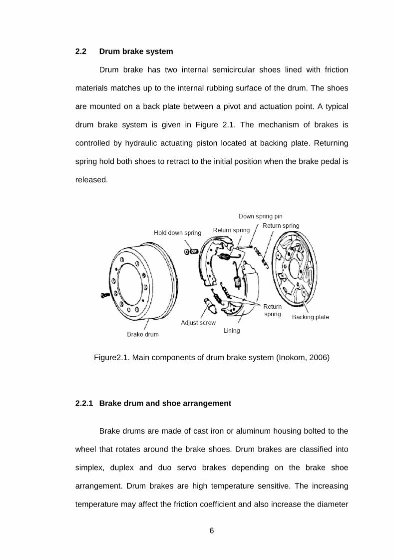
2.2 Drum brake system
Drum brake has two internal semicircular shoes lined with friction
materials matches up to the internal rubbing surface of the drum. The shoes
are mounted on a back plate between a pivot and actuation point. A typical
drum brake system is given in Figure 2.1. The mechanism of brakes is
controlled by hydraulic actuating piston located at backing plate. Returning
spring hold both shoes to retract to the initial position when the brake pedal is
released.
Figure2.1. Main components of drum brake system (Inokom, 2006)
2.2.1 Brake drum and shoe arrangement
Brake drums are made of cast iron or aluminum housing bolted to the
wheel that rotates around the brake shoes. Drum brakes are classified into
simplex, duplex and duo servo brakes depending on the brake shoe
arrangement. Drum brakes are high temperature sensitive. The increasing
temperature may affect the friction coefficient and also increase the diameter
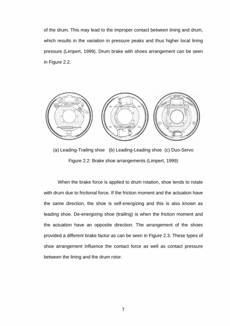
7
of the drum. This may lead to the improper contact between lining and drum,
which results in the variation in pressure peaks and thus higher local lining
pressure (Limpert, 1999). Drum brake with shoes arrangement can be seen
in Figure 2.2.
(a) Leading-Trailing shoe (b) Leading-Leading shoe (c) Duo-Servo
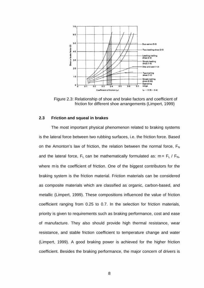
Figure 2.2: Brake shoe arrangements (Limpert, 1999)
When the brake force is applied to drum rotation, shoe tends to rotate
with drum due to frictional force. If the friction moment and the actuation have
the same direction, the shoe is self-energizing and this is also known as
leading shoe. De-energizing shoe (trailing) is when the friction moment and
the actuation have an opposite direction. The arrangement of the shoes
provided a different brake factor as can be seen in Figure 2.3. These types of
shoe arrangement influence the contact force as well as contact pressure
between the lining and the drum rotor.
8
Figure 2.3: Relationship of shoe and brake factors and coefficient of friction for different shoe arrangements (Limpert, 1999)
2.3 Friction and squeal in brakes
The most important physical phenomenon related to braking systems
is the lateral force between two rubbing surfaces, i.e. the friction force. Based
on the Amonton’s law of friction, the relation between the normal force, FN
and the lateral force, FL can be mathematically formulated as: m = FL / FN,
where m is the coefficient of friction. One of the biggest contributors for the
braking system is the friction material. Friction materials can be considered
as composite materials which are classified as organic, carbon-based, and
metallic (Limpert, 1999). These compositions influenced the value of friction
coefficient ranging from 0.25 to 0.7. In the selection for friction materials,
priority is given to requirements such as braking performance, cost and ease
of manufacture. They also should provide high thermal resistance, wear
resistance, and stable friction coefficient to temperature change and water
(Limpert, 1999). A good braking power is achieved for the higher friction
coefficient. Besides the braking performance, the major concern of drivers is
9
the annoying sounds also known as squeal generated during the braking
process.
Brake squeal is widely accepted as friction induced dynamic instability.
It is associated with the high level of vibration of the brake assembly when
the friction force is activated during the braking process. Brake squeal can be
described as an irritating sound with a main frequency between 1 to 15 kHz,
generated by the brake components (Papinniemi et al. (2002) and Ouyang et
al. (2005)). Previous researchers found that the presence of friction force into
the brake assembly was a major contributor towards the squeal propensity.
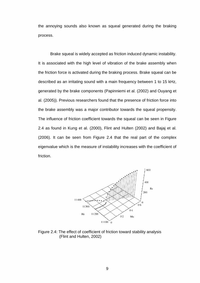
The influence of friction coefficient towards the squeal can be seen in Figure
2.4 as found in Kung et al. (2000), Flint and Hulten (2002) and Bajaj et al.
(2006). It can be seen from Figure 2.4 that the real part of the complex
eigenvalue which is the measure of instability increases with the coefficient of
friction.
Figure 2.4: The effect of coefficient of friction toward stability analysis (Flint and Hulten, 2002)

10
2.4 The mechanism of the brake squeal
There are several mechanisms which can be used to explain the
brake squeal phenomenon and these are described as follows:
2.4.1 Stick-slip theory
Friction produced by the contact of the shoe and drum in brake system
causes a stick-slip situation to occur, which is the primary reason for squeal.
Stick-slip refers to the phenomenon where friction coefficient mk was a
decreasing function of vs (Mc Millan, 1997). It is known that this relationship
can result in negative damping and lead to unstable oscillations. Stick
condition is occurs when the static friction coefficient is larger between two
surfaces. If an applied force is large enough to overcome the static friction,
the reduction of the friction to the kinetic friction can cause a sudden variation
in the velocity of the movement. In the stick phase, the applied tangential
force FT is exactly balanced by the frictional force F. This simply indicates
that the greater the applied force is, the greater the force due to static friction
will be and this can be described as:
mgFF smaxT m=£ (1)
In the case of slip, the effect of friction is to produce a force which opposes
the direction of motion. This relation can be described as:
0dvd
s
k <m
(2)

11
2.4.2 Sprag-slip theory
Sprag –slip or kinematics constraint or geometrically induced is used
to describe the theory of brake squeal. This theory was developed by
Spurr(1961) as mentioned by other researchers such as (Kinkaid, et al.
(2003), Ouyang et al. (2005) and Dai and Lim (2008). This model is very
significant in order to relate with the squeal propensity. The deformation of a
strut as it undergoes displacement due to friction causes the normal load to
increase and this in turn will increase the friction. The cycle continues until it
reaches an orientation known as sprag angle where further motion is
impossible. This action does not depend on a coefficient of friction varying
with the slipping velocity, but result from the geometric arrangement and
flexibility of the pad. He claimed that the variable contact both between the
piston and the backing plate and between the lining pad and rotor as a cause
of squeal propensity. The observation made by explaining how a pad with a
tapered shape achieves instability as the contact point shifted to the front of
the pivot. The developed idea was an important aspect in the design of disc
brake as the geometry of the pad should be as flat as possible to avoid the
pressure distribution from shifting to the pivot point.
Figure 2.5: Schematic of the tapered brake pad contacting a rotor used to explain the sprag-slip theory (Kinkaid et al. (2003)).
12
2.5 Previous brake squeal Prediction and testing
The mechanisms of squeal can be investigated, analyzed and
validated through methodologies such as vehicle testing, dynamometer test,
modal testing and finite element simulation. Studies of brake squeal can be
categorized into two methods which can be presented as experimental and
numerical analysis.
2.5.1 Experimental analysis
The experimental works on brake squeal have been carried out since
the mid-1970s. In 1978, work of Felske as reported by Kinkaid et al. (2003)
and Papinniemi et al. (2002) was carried out by using dual pulsed
holographic interferometry (DPHI). This experiment was successfully applied
to squealing brake systems. The mode shape from the vibrating object can
be determined by interpreting the fringe pattern. Fringe pattern can be
considered as topographical lines which give the absolute displacement of all
points on the object. The same method was also employed by Nishiwaki et
al. (1993), followed by Fieldhouse and Newcomb (1996) to investigate disc
brake noise. They conducted a parametric and geometric characteristic study
to determine the effect of component to the squeal propensity. They found
that pad leading edge abutment is extremely prone to squeal and concluded
that the noise can be linked to the coupling of the natural frequencies of the
individual parts when there are closed together.
13
McDaniel et al. (1999) studied acoustic radiation from a stationary
brake system. The methodology used in this study was the Laser Doppler
Vibrometer (LDV). The stationary brake was shaken by using the shaker
excitation at a certain frequency while LDV was directly scanned to one side
of the brake system. The methodology presented was independent of the
friction law, as the mechanical excitation used to excite the stationary brake
has created the interaction forces between the pad and rotor. The result
shows the good agreement as found in vibration patterns observed on
squealing brake system. They claimed that the rotor leads to flexural
wavelengths that are on the order of acoustic wavelengths.
Lee et al. (2001) studied the non-uniform cross sectional shoe which
was found to have an effect on the instability. They conducted an
experimental dynamometer test on a car drum brake. Modal analysis was
carried out for individual components followed by modal analysis for coupled
drum brake with an applied brake pressure. They found that the frequency
extraction for individual components is close to the coupled brake under an
applied braking pressure but only a small variation in shoe frequency. They
then conducted a theoretical model by including the kinetic and potential
energy between drum and shoe. According to Lee at al. (2001), squeal is
reduced when there is an increase of cross sectional area and a decrease of
bending stiffness. The minimum decreases of the cross section area could be
done by considering the strain energy distribution at the shoe back plate.
14
2.5.2 Analytical and numerical analysis
Most researches on brakes squeal focused on the numerical and
analytical methods due to a few reasons (Kinkaid et al, 2003) such as;
1) Expensive, this is mainly due to hardware cost and long turnaround
time for design iterations experimentally.
2) May predict the event at early design stage before production runs
3) May simulate different types of structure, operating condition and
materials compositions.
Brake squeal can be modeled by using analytical and numerical
methods to predict its occurrence. Modeling of the brake squeal is quite
challenging because brake system consists of a few components which may
contribute to a large number of degrees of freedom (d.o.f). Complex
eigenvalue analyses have been used to study the stability of the brake
system and predict the occurrence of the brake squeal. Through the complex
eigenvalue analyses the modal characteristic of the components can be
obtained. A latest review of brake squeal by Ouyang et al. (2005) revealed
that the analytical and numerical methods are still significant for brake squeal
studies. FEM was used to model the individual components of brake system
for the analysis.
Kung et al. (2000) studied on reducing low frequency squeal using
complex eigenvalue. They claimed that by changing the rotor material, it may
decouple the modal interaction and eliminate dynamic instability. Bajer et al.
(2003) combined a nonlinear static analysis and complex eigenvalue
15
extractions to study friction induced dynamic instability and proceed with
including lining wear effect to have a realistic contact patterns in Bajer et al.
(2004). According to Bajer et al. (2003, 2004), by including the positive
damping can result in eliminating some unstable modes at higher frequency
whilst including negative damping which does not trigger additional unstable
modes.
Work conducted by Fuadi (2003) used the finite element ANSYS for
modeling the drum brake system with three dimensional solid element. The
material properties are modeled in his analyses as linear elastic and
homogenous. He also incorporated the friction interface between the drum
and shoe by using the stiffness matrix and assuming that the contact
stiffness (kc) is uniformly distributed. By considering the contact stiffness
ranging from 70MN/m to 450 MN/m in his analysis resulted in 3 different
modes around 1300 Hz and 2000 Hz where these two modes tend to
coalesce when the coefficient of friction increases. Squeal occurred at the
minimum contact stiffness 90MN/m. He incorporated the damping effect and
found that squeal can be eliminated at higher frequency. Modification on the
shoe and drum back plate were made by changing their stiffness and found
that stiffening the drum and shoe back plate improves the system instability.
However his model did not validate with the experimental data.
Chung et al. (2003) conducted a virtual design of brake squeal. Their
work focused on design direction where they used baseline model to perform
sensitivity study and use the calculated sensitivity data to determine the
16
optimum combination to improve squeal noise. By introducing mode
convergence speed and examine the critical modes and its strain energy was
help to determine the effective changes to shift the natural frequency. They
found that by removing some material structure may shift natural frequency
and make minor influence on its mode shape and claimed that by separating
1.5% natural frequency is efficient way to suppress the system instability.
Bajaj et al. (2006) study the parametric sensitivity analysis on car
drum brake using complex eigenvalue. The purpose of their study is to
understand the mode “merging” and “veering” on the occurrence of brake
squeal. According to Bajaj, there were two conditions for mode merging: (1)
the separation between the frequencies of two modes of a statically coupled
system is sufficiently small, and (2) their component wise mode shapes
exhibit movement in opposite radial direction. When these two conditions are
met, the two modes have strong possibility to merge and can cause squeal in
the presence of friction coefficient. They found that the stability boundaries
are sensitive to changes in parameters such as lining stiffness. Decrease in
lining thickness increases in lining stiffness and may have different squeal
propensity. By incorporating the effect of hydraulic cylinder stiffness may
influence the stability of the system. However they did not furnish the
experimental results.
Liu et al. (2006) developed a finite element model of disc brake and
study the stability analysis using finite element ABAQUS. They found that
significant pad bending vibration may be responsible for causing the brake

17
squeal. They also investigated a few parameters such as brake pressure
applied and the stiffness of the rotor may also influence the stability of the
brake system. Increase the hydraulic pressure from 0.5 MPa to 2.0 MPa
increased the damping ratio and squeal propensity is increased. This is due
to the larger pressure inducing more friction between pad and disc. By
increasing the stiffness of the rotor can reduce the squeal propensity. Stiffen
the pad back plate cause a higher squeal propensity due to larger
deformation and vibration magnitude of the pad.
2.6 Study on brake contact pressure analysis
When the brake is applied, the brake line pressure acts on part of the
shoe back plate. This mechanism presses the friction material to form contact
to the inner drum wall. Contact distribution occurred at the shoe lining and it
has been reported that they are not uniformly distributed as established by
Day (1991), Hohmann et al. (1999), Eriksson (2000) as represented in Figure
2.6. This non-uniform pressure distribution is due to forces and moment
acting on the arrangement of brake shoes.
Figure 2.6: The distribution of braking force on brake shoe (Inokom, 2006)

18
Day (1991) investigated the drum brake interface pressure distribution
and found that the pressure distributions continually changed by the lining
wear. Heel and toe contact as described could result in increase of the brake
shoe factor whilst crown contact may decrease the brake shoe factor. He
also mentioned that drum flexure and shoe deformation will induce different
contact pressure distribution and resulted in non-uniform wear pattern. He
conducted an analysis on contact pressure for different shoe arrangements
and found that shoe sliding abutment show a greater tendency towards a U-
shape distribution than pivoted shoe drum brake as shown in Figure 2.7.
Figure 2.7: Drum brake pressure distributions (Day, 1991)

19
Hohmann et al. (1999) conducted a numerical simulation for drum
brake and has included applied brake pressure to press the lining plate to the
drum wall followed by rotating the drum for sliding motion to see the pressure
distribution pattern. This method considered the effect of stick-slip condition
that can explain the behavior of the contact pressure distribution. They used
an S-cam brake shoe for actuation mechanism. They found that contact
pressure distribution is higher on the lining plate close to the center of leading
edge for leading shoe whilst trailing shoe exhibit peak contact pressure at
cam side.
The surface roughness of the brake pad is a factor that lead to the
non-uniformity of the contact force and resulted in the highly localized
pressures. Eriksson (2000) revealed that only small parts of the surfaces
were in real contact. Sherif (2004) investigated the effect of surface
topography of pad/disc assembly towards squeal generation. He performed
an experiment to determine surface parameters of pad/disc assembly using
the Talyserf-5. When the squeal triggered both frictions pad and disc were
measured, he found that the glazed pad surface and worn-out disc were
likely to generate squeal but for glazed pad and abraded disc, no squeal
appeared. However, pad with the smooth disc is not suitable for squeal
establishment.
Huang and Shyr (2002) analyzed a drum brake using boundary
element method (BEM). A two-dimensional drum brake was modeled. Drum
was modeled as rigid body. Their early work was based on the similarity
20
between the calculated results and existing data before conducting the
analysis. The analysis was conducted by neglecting wear and thermal effect
and assumed that there was the perfect initial contact between the contact
surface of the lining plate and the circular profile of drum. Their report
showed that maximum pressure distribution was shifted from the supporting
point (pivot) towards the actuation side when the Young’s modulus of metal
shoe increased and resulted in more uniform pressure distribution. By
increasing the arc length of metal shoe, more pressure distribution was
achieved by decreasing the pressure close to the pivot point. They also
reported that the increase of thickness of the lining plate resulted in more
uniform pressure distribution. They also found that larger actuation force with
the actuation angle of 35o may improve the braking effort.
Ioannidis et al. (2003) conducted a non-linear analysis of a leading-
trailing shoe drum brake. A three dimensional finite element model of drum
brake was coupled with flexible-to-flexible surfaces contact algorithms. They
included the static contact at the first step followed by gradually applied
rotation to the drum. By considering uniform installation gap, they found that
there was still non-uniform pressure distribution on lining under perfect
contact condition. The location of the pressure distribution was higher at the
leading edge then trailing edge. Applying 0.3mm installation gap has resulted
in contact pressure pattern which was highly concentrated at the center of
the friction material for leading shoe. It has shown that the installation gap
can provide up to 60% of the maximum lining area in contact at leading shoe
whilst 25% of the maximum lining area for the trailing shoe. Latter in their

21
analysis, they also predicted the onset of squeal by using complex
eigenvalue method and found that under perfect initial contact (zero initial
gap), more unstable mode were produced compared to the initial uniform
installation gap of 0.3mm under the same actuation loads.
Contact problem required contact stiffness between the two contact
surfaces. The high stiffness value can lead to difficulties on convergence. But
the low contact stiffness may cause excessive penetration and large relative
displacement between the contacting nodes. This problem can cause
inaccurate simulation for the contact behavior. The best contact stiffness can
be estimated as:
linnlinn h/A.EK = (3)
Where:
Kn = contact stiffness at the nth element
An = area of the nth element
Elin = Young’s Modulus of the material for the contact problem
(Smaller values of E are chosen)
hlin = thickness of the lining.
The contact stiffness from contact analysis could affect the squeal to the
brake system. Elin is dependent on contact pressure at the friction interface
Bajaj et al. (2006). The unsuitable contact stiffness could lead to
convergence difficulties when performing analysis.

22
Work by Fuadi (2003) studied contact interaction between shoe lining
and drum wall of a drum brake. He assumed that the distribution of contact
stiffness along the mating surfaces as uniformly distributed and reported that
the minimum value for contact stiffness was 90MN/m. This resulted in squeal
generation even though uniform distribution was considered. Most of the
finite element model incorporates the geometric coupling between shoe and
rotor. This can be illustrated by a spring that links a pair of nodes on the
surface of the rotor and the shoe or pad in contact as shown in Figure 2.8.
Figure 2.8: Interface model spring stiffness with friction loading (Ouyang et al. (2005))
Bajaj et al. (2006) modeled and studied the parameter sensitivity
analysis of a car drum brake. They claimed that the interface pressure
distribution depended on the local contact pressure as work conducted by
Lee et al. (2003). Lee et al. (2003) performed the non-linear contact analysis
to determine the pressure distribution at the friction interface followed by
system linearization and a complex modal analysis. Contact stiffness
depended on the Young Modulus of the friction material. According to Ripin
et al. (2005), their work focused on the contact pressure of drum brake using
ABAQUS and then the value obtained from the contact interaction was used
to obtain the ratio for contact stiffness of Kc = 90MN/m as shown in the

23
equation (4). A two-dimensional finite element model has been developed to
carry out the contact pressure on the shoe lining.
cn
1ii
ici K
cp
cpkå
=
= (4)
The uniform contact which was obtained then was used to carry out the
stability analysis using the complex eigenvalue method. The result showed
that the non-uniform contact stiffness resulted in one unstable mode at
frequency of 1452 Hz. This is a good sign for further analysis by using the
contact stiffness ratio. However, there is a significant effect on the contact
pressure from the leading edge to the trailing edge.
Abu Bakar et al. (2003) investigated the influence of contact pressure
distribution on pad surface. The results showed that the higher contact
pressure occurred at the leading edge than the trailing. Some modifications
was made on the structures to improve the pressure distribution. The area of
contact pressure may vary due to the orientation of the components
installation. Increase in the contact area region would increase the uniform
distribution, thus reducing the squeal index. The work based on tribology was
also conducted by Abu Bakar et al. (2005). It was found that the contact area
increased as wear progresses in time, hence more uniform distribution was
achieved. It is a good reason for engineer to design the pad so that the
geometry of the brake would be considered in order to have a good uniform
contact and subsequently less partial wear at the certain portion of the pad.
24
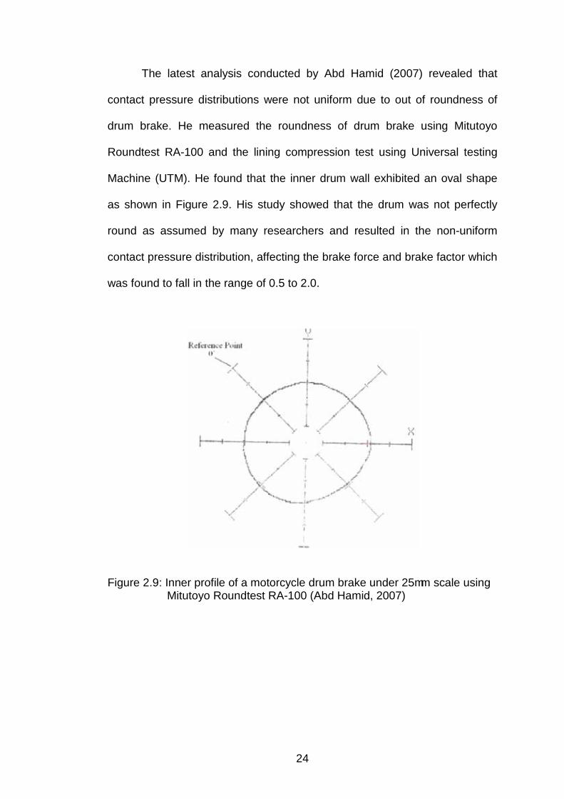
The latest analysis conducted by Abd Hamid (2007) revealed that
contact pressure distributions were not uniform due to out of roundness of
drum brake. He measured the roundness of drum brake using Mitutoyo
Roundtest RA-100 and the lining compression test using Universal testing
Machine (UTM). He found that the inner drum wall exhibited an oval shape
as shown in Figure 2.9. His study showed that the drum was not perfectly
round as assumed by many researchers and resulted in the non-uniform
contact pressure distribution, affecting the brake force and brake factor which
was found to fall in the range of 0.5 to 2.0.
Figure 2.9: Inner profile of a motorcycle drum brake under 25mm scale using Mitutoyo Roundtest RA-100 (Abd Hamid, 2007)