analysis of one and two-story single family home fire ... · analysis of one and two-story single...
TRANSCRIPT

Analysis of One and Two-Story Single Family Home Fire Dynamics and the Impact of Firefighter Horizontal Ventilation

Analysis of One and Two-Story Single Family Home Fire Dynamics
page 2
This paper describes experimental investigations on fire service ventilation practices in modern house geometries. Two houses were constructed inside a large fire facility. The first of two houses constructed was a one-story, 111.5 m2, 3 bedroom, 1 bathroom house with 8 total rooms. The second house was a two-story 297.3 m2, 4 bedroom, 2.5 bathroom house with 12 total rooms. The second house featured a modern open floor plan, two-story great room and open foyer. Fifteen experiments were conducted varying the ventilation locations and the number of ventilation openings. Ventilation scenarios included ventilating the front door only, opening the front door and a window near and remote from the seat of the fire, opening a window only and ventilating a higher opening in the two-story house. One scenario in each house was conducted in triplicate to examine repeatability. The results of these experiments examine potential occupant tenability and provide knowledge for the fire service for them to examine their horizontal ventilation standard operating procedures and training content. The fire dynamics resulting from ventilation practices such as ventilation near or remote from the seat of the fire and high versus low in relation to the fire are examined. Several other tactical considerations were developed utilizing the data from these experiments to provide specific examples of changes that can be adopted based on a departments current strategies and tactics. Such tactical considerations and a systems approach to fire service tactics should be investigated further.
Analysis of One and Two-Story Single Family Home Fire Dynamics and the Impact of Firefighter Horizontal Ventilation
IntroductionVentilation is frequently used as a firefighting tactic to control and fight fires. In firefighting, ventilation refers to the process of creating an opening so that heat and smoke will be released, permitting the firefighters to locate and attack the fire. If used properly, ventilation improves visibility and reduces the chance of flashover or back draft. However, poorly placed or timed
ventilation may increase the air supply to the fire, causing it to rapidly grow and spread [1].
When ventilation is increased, either through tactical action of firefighters or unplanned ventilation resulting from effects of the fire (e.g., failure of a window) or human action (e.g., door opened), heat release will increase, potentially resulting in flashover conditions. These changing fire conditions
Stephen Kerber

page 3
Analysis of One and Two-Story Single Family Home Fire Dynamics
are sometimes unexpectedly swift, providing little time for firefighters to react and respond. The changing dynamics of residential fires as a result of the changes in construction materials, building contents, and building size and geometry over the past 50 years add complexity to the influence of ventilation on fire behavior [2].
Traditional fire service training does not effectively replicate the impact of ventilation. A large number of fire training buildings are made of concrete or standard shipping containers and utilize small fuel loads to increase the safety of the training exercises. As a result, any ventilation practices utilized in these buildings leads to improved conditions. If instructors do not explain how these
training exercises differ from ventilation under real world conditions, firefighters may gain a false sense of reality and potentially use incorrect tactics during actual incidents.
The rate for traumatic firefighter deaths occurring outside structures or from cardiac arrest has declined while, at the same time, the rate of firefighter deaths occurring inside structures has continued to climb over the past 30 years [3]. It is believed that one significant contributing factor is the lack of understanding of fire behavior in residential structures resulting from both natural ventilation and the use of ventilation as a firefighter practice. Three recent ventilation related incidents have resulted in firefighter fatalities and were investigated by the
National Institute for Occupational Safety and Health (NIOSH). In 2010, a fire in a one-story house claimed the life of a firefighter and the investigation report suggests, ‘‘Fire departments should ensure that fire fighters and officers have a sound understanding of fire behavior and the ability to recognize indicators of fire development and the potential for extreme fire behavior [4].’’ The second incident occurred in 2000 and resulted in NIOSH suggesting, ‘‘Ventilation timing is extremely important and must be carefully coordinated between both fire attack and ventilation crews. [5].’’ A third incident in 2008 claimed the life of one firefighter and one civilian. The NIOSH report conclusion states ‘‘This contributory factor (tactical ventilation)
EXPERIMENT STRUCTURE LOCATION OF IGNITION VENTILATION PARAMETERS
1 1-Story Living Room Front door
2 2-Story Family Room Front door
3 1-Story Living Room Front door + LR window
4 2-Story Family Room Front door + FR1 window
5 1-Story Living Room LR window only
6 2-Story Family Room FR1 window only
7 1-Story Living Room Front door + BR2 window
8 2-Story Family Room Front door + BR3 window
9 1-Story Living Room Front door + LR window (Repeat Exp. 3)
10 2-Story Family Room Front door + FR1 window (Repeat Exp. 4)
11 2-Story Family Room Front door + FR1 window (Repeat Exp. 4)
12 1-Story Living Room Front door + LR window (Repeat Exp. 3)
13 2-Story Family Room Front door + FR3 Window
14 1-Story Living Room Front door + 4 windows (LR, BR1, BR2, BR3)
15 2-Story Family Room Front door + 4 windows (LR, Den, FR1, FR2)
Table 1: Experimental series

page 4
Analysis of One and Two-Story Single Family Home Fire Dynamics
points to the need for training on the influence of tactical operations (particularly ventilation) on fire behavior [6].’’ There has been little research conducted to provide the fire service with data they need to update their ventilation tactics especially with changes to the fire environment over the last several decades.
Traditionally, the fire service has adapted their tactics based on knowledge or experience gained while fighting fires and passing that information on through the generations. This approach can be very slow to adapt to changes and can be incorrect because rarely are two fires identical so the variables encountered are never well understood. The research in this study examines these variables to provide the scientific knowledge currently lacking in the fire service needed to supplement their training system.
Full-Scale House ExperimentsTo examine ventilation practices as well as the impact of changes in modern house geometries, two houses were constructed inside a large fire experimental facility. Fifteen experiments were conducted varying the ventilation locations and the number of ventilation openings (Table 1). Ventilation scenarios were designed to examine common fire service practices and included the following: ventilating the front door only, opening the front door and a window near and remote from the seat of the fire, opening a window only, and ventilating a higher opening in the two-story house. One scenario in each structure was conducted in triplicate to examine repeatability. Experiments in each house were conducted 3 days apart
to allow for ambient conditions inside the houses between 15 and 22°C and below 50% relative humidity prior to ignition.
One-Story Structure
Seven of the experiments took place in the one-story house. The house was designed to be representative of a home constructed in the mid-twentieth century with walls and doorways separating all of the rooms and 2.4 m ceilings. The one-story house had an area of 111.5 m2; with three bedrooms, one bathroom and eight total rooms (Figure 1). The home was wood framed, lined with two layers of gypsum board (Base layer 16 mm, Surface layer 13 mm) to protect the structure and allow for multiple experiments. All of the windows were filled with plugs so that window opening could be controlled by removing the plugs at the time specified for each experiment.
Two-Story Structure
The two-story house had an area of 297.3 m2; with four bedrooms, 2.5 bathrooms house and 12 total rooms (Figures 2, 3). The house incorporated modern features such as an open floor plan, two-story great room, and open foyer. The home was also a wood framed structure lined with two layers of gypsum board (Base layer 16 mm, Surface layer 13 mm). All of the windows were filled with plugs so that window opening could be controlled by removing the plugs at the time specified for each experiment.
Fuel Load
Both houses were furnished with like furnishings. Figures 4, 5 6 show three dimensional renderings of both houses with furniture locations. The living
room (LR) in the one-story house, along with the family room and the LR in the two-story house, were furnished similarly with two sofas, armoire, television, end table, coffee table, chair, two pictures, lamp with shade and two curtains. The floor was covered with polyurethane foam padding and polyester carpet. The fuel loading was approximately 29 kg/m2.
In order to characterize the living/family room fuel load it was placed in a 5.5 m wide by 4.0 m deep room with a 2.4 m high ceiling. The room had a 3.7 m wide by 2.1 m tall opening on the front wall. The room was placed under an oxygen consumption calorimeter and a peak heat release rate of 11.3 MW was measured.
Bedroom 1 in both houses was furnished with a queen bed comprised of a mattress, box spring, wood frame, two pillows and comforter. The room also contained a dresser, armoire and television. The floor was covered with polyurethane foam padding and polyester carpet. The remainder of the bedrooms (2–4) in both houses was furnished with the same bed, armoire, television and flooring compliment as well as a smaller dresser, headboard, and a framed mirror.
The dining room of both houses was furnished with a solid wood table and four upholstered chairs. The kitchens were furnished with the same table and chairs as the dining room, as well as a dishwasher, stove, refrigerator and oriented strand board base cabinets with cement board counters. The floors of both rooms were also cement board to simulate a tile floor. The two-story house also had a den on the first floor in which a stuffed chair was placed as a target fuel.

page 5
Analysis of One and Two-Story Single Family Home Fire Dynamics
Instrumentation
The measurements taken during the experiments included gas temperature, gas velocity, gas concentrations, and video recording. Gas temperature was measured with bare-bead, Chromel–Alumel (type K) thermocouples, with a 0.5 mm nominal diameter. Thermocouple arrays locations are shown in Figures 1, 2 and 3. The thermocouples were located in the LR and hallway in the one-story house and foyer and second floor hallway
in the two-story house. Each location had an array of thermocouples with measurement locations of 0.03 m, 0.3 m, 0.6 m, 0.9 m, 1.2 m, 1.5 m, 1.8 m and 2.1 m below the ceiling. The thermocouple arrays located in the dining room, kitchen, den and bedrooms had measurement locations of 0.3 m, 0.9 m, 1.5 m, and 2.1 m below the ceiling. The family room had thermocouple locations every 0.3 m below the ceiling down to the floor.
Gas velocity was measured utilizing
differential pressure transducers connected to bidirectional velocity probes. These probes were located in the front doorway and the window used for ventilation (Figures 1, 2, 3). There were five probes on the vertical centerline of each doorway located at 0.3 m from the top of the doorway, the center of the doorway, and 0.3 m from the bottom of the doorway. Thermocouples were co-located with the bidirectional probes to complete the gas velocity measurement.
Figure 1: One-Story house floor plan
Figure 2: Two-Story house first floor plan Figure 3: Two-Story house second floor plan

page 6
Analysis of One and Two-Story Single Family Home Fire Dynamics
Gas concentrations of oxygen, carbon monoxide, and carbon dioxide were measured in four locations in the structure. Concentrations were measured at 0.3 m and 1.5 m from the floor in the LR and at 1.5 m from the floor in bedrooms 2 and 3 of the one-story house (Figure 1). Concentrations were measured at 0.3 m and 1.5 m from the floor in the family room and second floor hallway of the two-story house (Figures 2, 3). Gas concentration measurements after water flow into the structure may not be accurate due to the impact of moisture on the gas measurement equipment.
Video cameras were placed inside and outside the building to monitor both smoke and fire conditions throughout each experiment. Eight video camera views were recorded during each experiment.
Experimental Methodology
All of the experiments began with all of the exterior doors and windows closed and all of the interior doors in the same locations, either open or closed. The interior doors to Bedroom 3 in the one-story house and Bedroom 2 in the
two-story house were closed for every experiment. The fire was ignited on a sofa in the LR of the one-story house (Figure 4) and on a sofa in the family room for the two-story house (Figure 6) using a remote ignition device comprised of three stick matches.
The flaming fire was allowed to grow until ventilation operations were simulated. The one-story house was ventilated at 8 min after ignition. This was determined based on three factors; time to achieve ventilation limited conditions in the house, potential response and intervention times of the fire service, and window failure times from previous window failure experiments [7]. The two-story house was ventilated 10 min after ignition. The additional 2 min enabled ventilation limited conditions, as the larger volume needed more time to consume the available oxygen.
When more than one ventilation opening was created in an experiment, such as opening the door and a window, the subsequent openings were made in 15 s intervals. This time was arrived at by assuming well timed and efficient
ventilation by the fire service independent of the ventilation scenario.
After ventilation, the fire was allowed to grow until flashover or perceived maximum burning rate based on the temperatures, observation of exterior conditions, and monitoring of the internal video. Once the fire maintained a peak for a period of time, with respect given to wall lining integrity, a firefighting hose stream was flowed in through an external opening. The experiment was terminated approximately 1 min after the hose stream, and suppression was completed by a deluge sprinkler system and the firefighting crew.
One-Story Experimental Results
Seven experiments were conducted in the one-story structure (Table 1). Data graphs are provided for temperatures throughout the structure at 2.1 m and 0.9 m from the floor for each experiment. Each graph has the events labeled across the top with a vertical line indicating when they occurred. Additional data for each experiment including temperatures at additional elevations, gas concentrations, and gas velocities is
Figure 5: 3D rendering of the One-Story house Figure 6: 3D rendering of the Two-Story house Figure 7: 3D rendering of the First Floor of the Two-Story house
page 7
Analysis of One and Two-Story Single Family Home Fire Dynamics
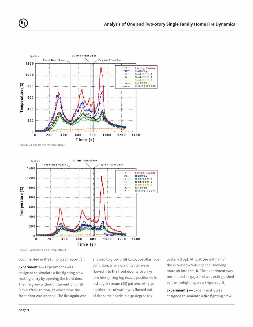
documented in the full project report [7].
Experiment 1 — Experiment 1 was designed to simulate a fire fighting crew making entry by opening the front door. The fire grew without intervention until 8 min after ignition, at which time the front door was opened. The fire again was
allowed to grow until 12:30, post-flashover condition, when 10 s of water were flowed into the front door with a 379 lpm firefighting fog nozzle positioned in a straight stream (SS) pattern. At 13:30 another 10 s of water was flowed out of the same nozzle in a 30 degree fog
pattern (Fog). At 14:15 the left half of the LR window was opened, allowing more air into the LR. The experiment was terminated at 15:30 and was extinguished by the firefighting crew (Figures 7, 8).
Experiment 3 — Experiment 3 was designed to simulate a fire fighting crew
Figure 7: Experiment 1-2.1 m temperatures
Figure 8: Experiment 1-0.9 m temperatures

page 8
Analysis of One and Two-Story Single Family Home Fire Dynamics
making entry through the front door and having a ventilation opening made shortly after near the seat of the fire. The fire grew without intervention until 8 min after ignition, at which time the front door was opened. Fifteen seconds later, the LR window was opened. The fire again was allowed to grow until 10:22 when 10 s of water were flowed into the
LR window with a firefighting fog nozzle positioned in a straight stream pattern. The experiment was terminated at 11:30 and was extinguished by the firefighting crew (Figures 9, 10).
Experiment 5 — Experiment 5 was designed to simulate a fire fighting crew making a ventilation opening near
the seat of the fire prior to entry. The fire grew without intervention until 8 min after ignition, at which time the LR window was opened. The fire again was allowed to grow until 11:32 when 10 s of water were flowed into the LR window with a firefighting fog nozzle positioned in a straight stream pattern. The experiment was terminated at 12:45 and
Figure 9: Experiment 3-2.1 m temperatures
Figure 10: Experiment 3-0.9 m temperatures

page 9
Analysis of One and Two-Story Single Family Home Fire Dynamics
was extinguished by the firefighting crew (Figures 11, 12).
Experiment 7 — Experiment 7 was designed to simulate a fire fighting crew making entry through the front door and having a ventilation opening made shortly after, remote from the seat of the fire. The fire grew without intervention
until 8 min after ignition, at which time the front door was opened, followed 15 s later by the opening of the Bedroom 2 (BR2) window. The fire again was allowed to grow until 15:46 when 10 s of water were flowed into the front door with a irefighting fog nozzle positioned in a straight stream pattern. The experiment
was terminated at 16:40 and was extinguished by the firefighting crew (Figures 13, 14).
Experiment 9 — Experiment 9 replicated Experiment 3 and was the second of three replicate experiments to examine repeatability. The fire grew without intervention until 8 min after
Figure 11: Experiment 5-2.1 m temperatures
Figure 12: Experiment 5-0.9 m temperatures

page 10
Analysis of One and Two-Story Single Family Home Fire Dynamics
ignition, at which time the front door was opened. Fifteen seconds after the front door was opened, the LR window was opened. The fire again was allowed to grow until 11:12 when 10 s of water were flowed into the LR window with a firefighting fog nozzle positioned in a straight stream pattern. The experiment
was terminated at 12:20 and was extinguished by the firefighting crew (Figures 15, 16).
Experiment 12 — Experiment 12 was the third of three replicate experiments to examine repeatability. The fire grew without intervention until 8 min after
ignition, at which time the front door was opened. Fifteen seconds after the front door was opened, the LR window was opened. The fire again was allowed to grow until 11:09 when 10 s of water were flowed into the LR window with a firefighting fog nozzle positioned in a straight stream pattern. The experiment
Figure 13: Experiment 7-2.1 m temperatures
Figure 14: Experiment 7-0.9 m temperatures

page 11
Analysis of One and Two-Story Single Family Home Fire Dynamics
was terminated at 12:20 and was extinguished by the firefighting crew (Figures 17, 18).
Experiment 14 — Experiment 14 was designed to examine the impact of ventilating with several openings. The fire grew without intervention until 8
min after ignition, at which time the front door was opened. Fifteen seconds after the front door was opened, the LR window was opened. In fifteen second intervals, the Bedroom 1 (BR1) window, Bedroom 2 (BR2) window, and Bedroom 3 (BR3) window were opened. The fire
again was allowed to grow until 13:02 when 10 s of water were flowed into the LR window with a firefighting fog nozzle positioned in a fog stream pattern. The experiment was terminated at 14:10 and was extinguished by the firefighting crew (Figures 19, 20).
Figure 15: Experiment 9-2.1 m temperatures
Figure 16: Experiment 9-0.9 m temperatures
page 12
Analysis of One and Two-Story Single Family Home Fire Dynamics
Two-Story Experimental Results
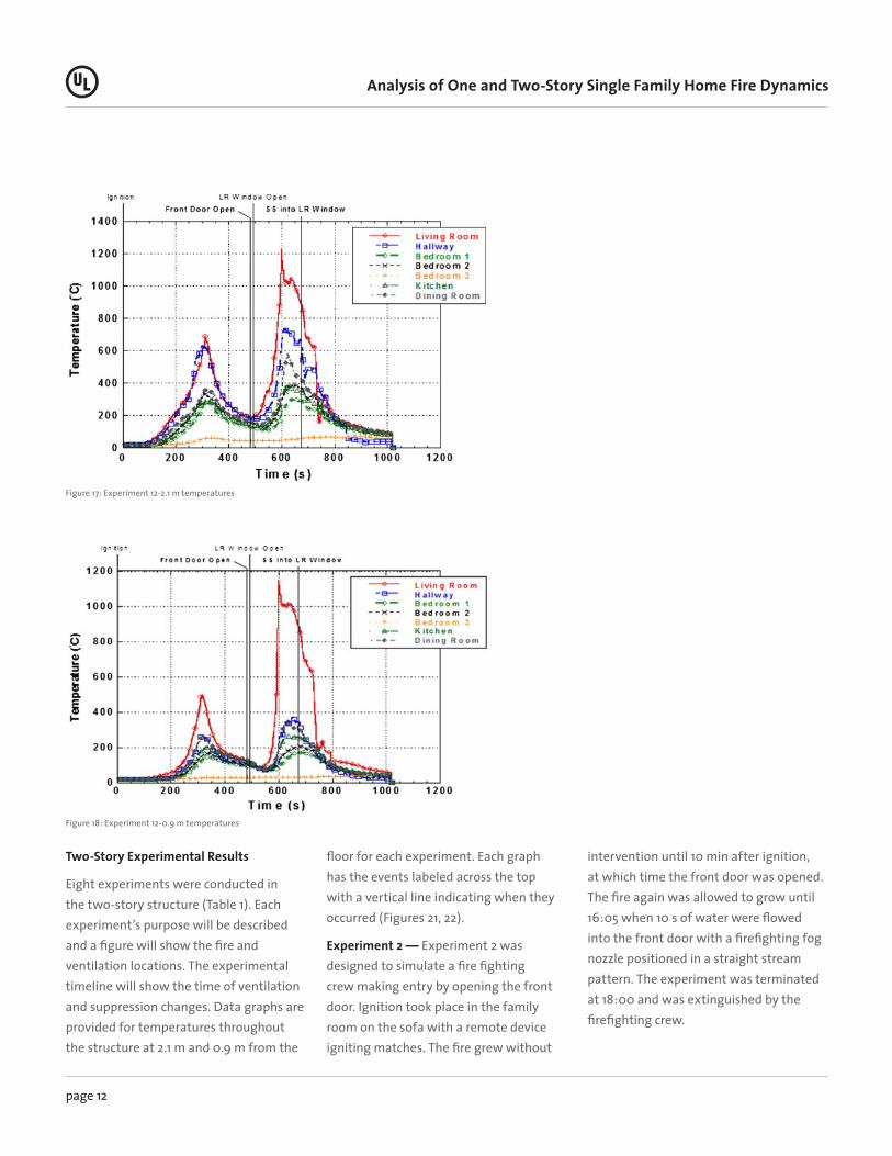
Eight experiments were conducted in the two-story structure (Table 1). Each experiment’s purpose will be described and a figure will show the fire and ventilation locations. The experimental timeline will show the time of ventilation and suppression changes. Data graphs are provided for temperatures throughout the structure at 2.1 m and 0.9 m from the
floor for each experiment. Each graph has the events labeled across the top with a vertical line indicating when they occurred (Figures 21, 22).
Experiment 2 — Experiment 2 was designed to simulate a fire fighting crew making entry by opening the front door. Ignition took place in the family room on the sofa with a remote device igniting matches. The fire grew without
intervention until 10 min after ignition, at which time the front door was opened. The fire again was allowed to grow until 16:05 when 10 s of water were flowed into the front door with a firefighting fog nozzle positioned in a straight stream pattern. The experiment was terminated at 18:00 and was extinguished by the firefighting crew.
Figure 17: Experiment 12-2.1 m temperatures
Figure 18: Experiment 12-0.9 m temperatures

page 13
Analysis of One and Two-Story Single Family Home Fire Dynamics
Experiment 4 — Experiment 4 was designed to simulate a fire fighting crew making entry through the front door and having a ventilation opening made shortly after, near the seat of the fire. Ignition took place in the LR on the sofa with a remote device igniting matches. The fire grew without intervention until 10 min after ignition, at which time the front door was opened. Fifteen seconds
later, the first floor family room (FR1) window was opened. The fire again was allowed to grow until 17:31 when 10 s of water were flowed into the family room window with a firefighting fog nozzle positioned in a straight stream pattern. The experiment was terminated at 18:30 and was extinguished by the firefighting crew (Figures 23, 24).
Experiment 6 — Experiment 6 was designed to simulate a fire fighting crew making a ventilation opening near the seat of the fire prior to entry. Ignition took place in the family room on the sofa. The fire grew without intervention until 10 min after ignition, at which time the first floor family room (FR1) window was opened. The fire again was allowed to grow until 16:32 when 10 s of water
Figure 19: Experiment 14-2.1 m temperatures
Figure 20: Experiment 14-0.9 m temperatures

page 14
Analysis of One and Two-Story Single Family Home Fire Dynamics
were flowed into the family room (FR1) window with a firefighting fog nozzle positioned in a straight stream pattern. The experiment was terminated at 17:30 and was extinguished by the firefighting crew (Figures 25, 26).
Experiment 8 — Experiment 8 was designed to simulate a fire fighting crew making entry through the front door and having a ventilation opening made
shortly after remote from the seat of the fire. Ignition took place in the family room on the sofa. The fire grew without intervention until 10 min after ignition, at which time the front door was opened followed 15 s later by the opening of the Bedroom 3 (BR3) window. The fire again was allowed to grow until 17:32 when 10 s of water were flowed into the BR3 window with a firefighting fog nozzle
positioned in a straight stream pattern. The experiment was terminated at 18:30 and was extinguished by the firefighting crew (Figures 27, 28).
Experiment 10 — Experiment 10 was the second of three replicate experiments to examine repeatability. Ignition took place in the family room on the sofa. The fire grew without intervention until 10 min after ignition, at which time the front
Figure 21: Experiment 2-2.1 m temperatures
Figure 22: Experiment 2-0.9 m temperatures

page 15
Analysis of One and Two-Story Single Family Home Fire Dynamics
door was opened. Fifteen seconds after the front door was opened the family room (FR1) window was opened. The fire again was allowed to grow until 24:16 when 10 s of water were flowed into the family room window with a firefighting fog nozzle positioned in a straight stream pattern. The experiment was terminated at 25:30 and was extinguished by the firefighting crew (Figures 29, 30).
Experiment 11 — Experiment 11 was the third of three replicate experiments to examine repeatability. Ignition took place in the family room on the sofa. The fire grew without intervention until 10 min after ignition, at which time the front door was opened. Fifteen seconds after the front door was opened, the family room (FR1) window was opened. The fire again was allowed to grow until 15:17
when 10 s of water were flowed into the family room window with a firefighting fog nozzle positioned in a straight stream pattern. The experiment was terminated at 16:30 and was extinguished by the firefighting crew (Figures 31, 32).
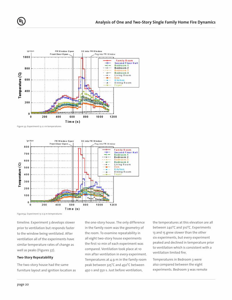
Experiment 13 — Experiment 13 was designed to examine the impact of ventilation horizontally as high as possible near the seat of the fire. Ignition
Figure 23: Experiment 4-2.1 m temperatures
Figure 24: Experiment 4-0.9 m temperatures

page 16
Analysis of One and Two-Story Single Family Home Fire Dynamics
took place in the family room on the sofa. The fire grew without intervention until 10 min after ignition, at which time the front door was opened. Fifteen seconds after the front door was opened, the second floor family room (FR3) window was opened. The fire again was allowed to grow until 12:28 when 10 s of water were flowed into the FR3 window with
a firefighting fog nozzle positioned in a straight stream pattern. A second 10 s burst of water was directed into the same window at 14:28 with the same nozzle positioned in a fog pattern. The experiment was terminated at 15:30 and was extinguished by the firefighting crew (Figures 33, 34).
Experiment 15 — Experiment 15 was designed to examine the impact of ventilating with several openings. Ignition took place in the family room on the sofa. The fire grew without intervention until 10 min after ignition, at which time the front door was opened. Fifteen seconds after the front door was opened, the LR (LR) window was opened. In fifteen
Figure 25: Experiment 6-2.1 m temperatures
Figure 26: Experiment 6-0.9 m temperatures

page 17
Analysis of One and Two-Story Single Family Home Fire Dynamics
second intervals, the den window, FR1 window, and FR2 window were opened. The fire again was allowed to grow until 14:33 when 10 s of water were flowed into the FR1 window with a firefighting fog nozzle positioned in a fog stream pattern. The experiment was terminated at 16:00 and was extinguished by the firefighting crew (Figures 35, 36).
DiscussionThe repeatability of these experiments was examined by comparing the first 8 min of the one-story experiments and the first 10 min of the two-story experiments. Another important factor in these experiments is tenability of potential occupants in the structures prior to fire department intervention, as well
as after fire department intervention. Firefighter ventilation practices will also be discussed. The temperature data will be compared to examine the conditions in the houses dependent upon which ventilation openings are made. Firefighters are taught to ventilate based on the location of the fire and in coordination with the operation that is
Figure 27: Experiment 8-2.1 m temperatures
Figure 28: Experiment 8-0.9 m temperatures

page 18
Analysis of One and Two-Story Single Family Home Fire Dynamics
being implemented. These comparisons provide a way to examine why they are taught those strategies and what those concepts mean for the tenability and fire dynamics within the houses.
One-Story Repeatability
In order to compare the ventilation practices, great emphasis was placed on
ensuring pre-ignition conditions were as identical as possible. Multiple pieces of the same furniture were purchased and the positioning of the furniture was the same between experiments. Ignition was initiated in the same location and the amount of air leakage area was controlled by filling cracks around the doors and windows with fiberglass insulation.
Of the seven experiments, Experiment 3 had a slower growing fire and Experiment 14 had a faster growing fire. The other five experiments grew similarly for the first 8 min before ventilation. Temperatures near the ceiling in the LR of the five similar experiments reached approximately 700°C at around 320 s and quickly decreased to 175°C at 480 s as
Figure 29: Experiment 10-2.1 m temperatures
Figure 30: Experiment 10-0.9 m temperatures

page 19
Analysis of One and Two-Story Single Family Home Fire Dynamics
the oxygen was consumed in the house. The temperatures at the same elevation in Bedroom 2 (most remote from the LR) reached 350°C before decreasing to an average of 150°C as the fire became ventilation limited.
As a whole, the set of experiments in the one-story structure showed repeatability prior to ventilation. The two experiments
which showed different growth rates from the others, 3 and 14, still had similar temperatures at the time of ventilation. Every experiment was within 50°C at the time of ventilation at the two measurement locations chosen, which were remote from each other.
Experiments 3, 9 and 12 followed the same timeline to examine repeatability
during the entire experiment. In all three experiments, the front door was opened at 8 min and the LR window was opened 15 s later. The fire was allowed to burn until a post flashover condition was reached. Figure 37 shows the temperature versus time at 2.1 m above the floor in the LR and bedroom 2 (BR2). Experiments 9 and 12 were similar throughout the entire
Figure 31: Experiment 11-2.1 m temperatures
Figure 32: Experiment 11-0.9 m temperatures
page 20
Analysis of One and Two-Story Single Family Home Fire Dynamics
timeline. Experiment 3 develops slower prior to ventilation but responds faster to the window being ventilated. After ventilation all of the experiments have similar temperature rates of change as well as peaks (Figures 37).
Two-Story Repeatability
The two-story house had the same furniture layout and ignition location as
the one-story house. The only difference in the family room was the geometry of the room. To examine repeatability in all eight two-story house experiments the first 10 min of each experiment was compared. Ventilation took place at 10 min after ventilation in every experiment. Temperatures at 4.9 m in the family room peak between 325°C and 450°C between 450 s and 550 s. Just before ventilation,
the temperatures at this elevation are all between 240°C and 310°C. Experiments 13 and 15 grew slower than the other six experiments, but every experiment peaked and declined in temperature prior to ventilation which is consistent with a ventilation limited fire.
Temperatures in Bedroom 3 were also compared between the eight experiments. Bedroom 3 was remote
Figure 33: Experiment 13-2.1 m temperatures
Figure34: Experiment 13-0.9 m temperatures

page 21
Analysis of One and Two-Story Single Family Home Fire Dynamics
from the family room and is a good indication of heat flow to the second floor of the house. At 2.1 m above the floor in Bedroom 3, all of the temperatures peaked around 200°C and leveled off or slightly decreased up to the time of ventilation.
Experiments 4, 10 and 11 followed the same timeline to examine repeatability
during the entire experiment. In all three experiments, the front door was opened at 10 min and the FR1 window was opened 15 s later. The fire was allowed to burn until a post flashover condition was reached. Figure 38 shows the temperature versus time at 4.9 m above the floor in the Family Room and Bedroom 2. Each of these experiments followed similar
trends, however had very different times to peak after ventilation. In experiments 4 and 11 the fire spread to both sofas in the family room before becoming ventilation limited. In Experiment 10 this did not occur, therefore, the fire grew more slowly after ventilation. Once the second sofa became involved in the fire, the temperatures near the ceiling of the
Figure 35: Experiment 15-2.1 m temperatures
Figure 36: Experiment 15-0.9 m temperatures

page 22
Analysis of One and Two-Story Single Family Home Fire Dynamics
family room increased at a similar rate as the other two replicate experiments (Figures 38).
Tenability
Two measures of tenability were used during these experiments; temperature and gas concentration. In order to estimate the time to untenability for potential occupants, the fractional
effective dose (FED) methodology from ISO 13571 [8] was utilized. This methodology provides specified thresholds and allows for calculation of time to incapacitation based on an accumulated exposure to either heat or toxic gases. Two typical thresholds were chosen for this analysis; FED = 0.3 and FED = 1.0. FED = 0.3 is the criterion used to
determine the time of incapacitation of susceptible people (11% of the population) and FED = 1.0 is used for healthy adults (50% of the population).
FED’s were calculated for elevations of 0.3 m and 1.5 m from the floor for both houses. The 1.5 m elevation is representative of a person’s head height while walking and the 0.3 m elevation is
Figure 37: Exp. 3, 9, 12 Repeatability—2.1 m temperatures
Figure 38: Exp. 4, 10, 11 Repeatability—4.9 m family room temperatures

page 23
Analysis of One and Two-Story Single Family Home Fire Dynamics
representative of the worst case scenario of a person lying on the floor. The time to exceed the thresholds for all of the experiments in each house for both heat and carbon monoxide were averaged and shown in Tables 2 and 3.
Examining the average FED’s, it is clear that heat causes incapacitation prior to the toxic gases in these experiments. If the occupant was in the living/family room or standing (1.5 m) in the open bedrooms, the average times to
incapacitation in the one and two-story houses occur prior to the simulated fire department arrival at 8 min or 10 min after ignition. Incapacitation of victims lying on the floor (0.3 m) in the bedrooms occurred after fire department
TEMPERATURE CARBON MONOXIDE
0.3 M 1.5 M 0.3 M 1.5 M
0.3 1 0.3 1 0.3 1 0.3 1
Living Room 5:31 6:08 4:05 4:27 7:30 9:15 6:12 7:09
Bedroom 1 11:30 NA 5:19 6:26 - - - -
Bedroom 2 11:46 NA 5:02 5:36 - - 6:19 7:20
Bedroom 3 NA NA NA NA - - NA NA
TEMPERATURE CARBON MONOXIDE
0.3 M 1.5 M 0.3 M 1.5 M
0.3 1 0.3 1 0.3 1 0.3 1
Family Room 6:30 7:38 5:45 6:22 15:46 16:00 14:56 18:34
Bedroom 1 12:25 17:27 7:10 9:27 - - - -
Bedroom 2 NA NA NA NA - - - -
Bedroom 3 8:10 12:58 6:17 7:35 - - - -
Bedroom 3 10:53 16:11 6:28 7:53 - - - -
Kitchen 15:19 17:28 6:52 8:08 - - - -
Second Floor Hall - - - - 16:00 18:47 12:52 16:54
Table 2: FED results for the One-Story house
Table 2: FED results for the Two-Story house
NA, not achieved; –, not a measurement locationNote: Temperature results standard deviation = 1:33, carbon monoxide results standard deviation = 1:54
NA, not achieved; –, not a measurement locationNote: Temperature results standard deviation = 3:50, carbon monoxide results standard deviation = 5:31

page 24
Analysis of One and Two-Story Single Family Home Fire Dynamics
ventilation, or did not occur in the bedroom with the closed door. This demonstrates two important concepts;
1. it is evident that there are places in these homes where people could be in need of rescue, and
2. firefighter ventilation practices need to be done properly because they can have a significant impact on the occupants inside the structure.
Ventilate Near and Remote to the Fire
The main guidance firefighters are given in their basic ventilation training is to ventilate as close to the seat of the fire as possible. This is meant to release the heat and smoke from the fire and to localize the growth of the fire to the area of origin. Ventilating remote from the seat of the fire creates the potential to spread the fire to uninvolved parts of the house by creating a flow path and source of oxygen from that uninvolved area.
Experiment 12 and Experiment 7 in the one-story house are compared in Figure 39. The RED lines represent the temperatures 1.5 m above the floor during the experiment when the front door was opened, followed by opening the LR window. The BLUE lines are measurements in the same locations but from the experiment where the front door was opened followed by the opening of the window in Bedroom 2, remote from the fire. The graph shows a slightly faster growing fire when ventilated near the seat of the fire. This can be expected because the source of oxygen is in the fire room and the fire
can react to this and increase its heat release rate. The bedrooms also increase in temperature but Bedroom 2 only peaks at approximately 250°C and Bedroom 1 peaks at 210°C. Then they begin to decrease in temperature because of the lack of oxygen available to burn at that side of the house.
When ventilated remote from the seat of the fire, the LR temperature does not peak as high because it has less oxygen supplied to it. The difference is in the bedrooms. An area that was previously limited in temperature because it was out of the flow path has now become part of the flow path. This increases the temperatures to close to 500°C in Bedroom 2 and up to 300°C in Bedroom 1. If the fire had not been suppressed in order to save the structure for subsequent experiments, both bedrooms would have become involved in fire, creating an undesired situation from a ventilation choice. Bedroom 3 was unaffected by either ventilation scenario because the door was closed (Figures 39).
Experiment 4 and Experiment 8 in the two-story house are compared in Figure 40. The RED lines represent the temperatures 1.5 m above the floor during the experiment where the front door was opened, followed by opening the family room window (FR1). The BLUE lines are measurements in the same locations but from the experiment where the front door was opened followed by the opening of the window in Bedroom 3. Ventilating near the seat of the fire localizes the combustion. This also creates the highest peak temperature (775°C) in the family room because all of the available oxygen is coming right into the family room.
Unlike the ranch house, ventilating near the seat of the fire peaked later than ventilating remote from the seat of the fire because the remote vent location was on the second floor which allowed more air to enter from the front door and grow the fire. This air was limited, which did not allow for temperatures to peak as high as the experiment with two ventilation points near the seat of the fire. Comparing the bedroom temperatures highlights the impact of creating a flow path through the bedroom. When Bedroom 3 was not in the flow path, its peak temperature was 250°C. However, when it was in the flow path, temperatures increased to 575°C.
Ventilating High Versus Ventilating Low
When determining how to most effectively ventilate a room, it would be intuitive to ventilate near the top of the room since that is where the hot gases from a fire develop a layer. One must also consider how the cool air enters the room as the hot gases are leaving the room. If the fire is ventilation limited, than the additional air can generate more energy than can be exhausted out of the ventilation openings. In this scenario, ventilating the top of the room did not provide the temperature relief that was intended.
The temperatures at 0.3 m above the floor and 4.9 m above the floor are plotted in Figure 41. In Experiments 11 and 13, the fire grew, became ventilation limited and then the temperatures decreased. Once the door and window were opened, the high ventilation window caused temperatures to increase much faster than the low ventilation window. The

page 25
Analysis of One and Two-Story Single Family Home Fire Dynamics
high window experiment reached 950°C at the ceiling and 650°C at the floor at approximately 720 s. The low window experiment reached 800°C at the ceiling and 500°C at the floor at approximately 870 s.
This is a dramatic difference in fire growth. Allowing air into a ventilation limited fire low and letting the hot gases
out high can create prime conditions for a flashover, even in a large volume like the two-story family room. Another point illustrated by this graph is that the family room did not cool much, if at all, when the high window was ventilated. The temperature 0.3 m above the floor did not decrease from 125°C before it increased exponentially to 650°C. This
is counterintuitive to the reason the fire service would create a ventilation opening in the first place, which is to reduce the temperature low in the room where they would be operating. In this case, the ventilation limited fire responded so quickly to the additional air that it did not cool the family room.
Figure 40: Comparison of family room and bedroom temperatures at 1.5 m above the floor
Figure 39: Comparison of living room and bedroom temperatures at 1.5 m above the floor when ventilated near and remote from the fire

page 26
Analysis of One and Two-Story Single Family Home Fire Dynamics
ConclusionsThis study consisted of a series of 15 full-scale residential structure fires to examine fire behavior and the impact of firefighter ventilation tactics. This fire research project developed the empirical data needed to quantify the fire behavior associated with these scenarios, and to develop the necessary firefighting ventilation practices to reduce firefighter death and injury.
The fires in both houses repeated ventilation limited conditions, which was necessary to assess the different ventilation practices of the fire service. Tenability in these two homes was limited for occupants. But the possibility of savable lives, especially behind closed doors, should be considered by the fire service in their risk analysis. The results of this series of experiments were similar to other studies; when a flaming furniture fire occurs in a home, occupants have a short time to evacuate safely. This
furthers the need for smoke alarms and residential sprinkler systems to increase occupant safety.
This research study developed empirical fire experiment data to demonstrate fire behavior resulting from one and two-story home fires and the impact of ventilation opening locations during fire service operations. This data has been used to provide education and guidance to the fire service in proper use of ventilation as a firefighting tactic that will result in mitigation of the firefighter injury and death risk associated with improper use of ventilation [9].
Future Research NeedsThere are several variable changes that could be done to further validate and expand the conclusions from this series of experiments. The first variable that could be altered is the fire location. These experiments focused on LR or family room fires. Additional experiments with fires in
the kitchen or bedrooms would allow for analysis of fire spread from these locations.
Future experiments should also consider creating a ventilation opening after one already exists (from the fire creating one of its own by failing a window, or a door being left open by an escaping occupant, or a window left open on a warm day). There are also two more types of ventilation in addition to horizontal ventilation that are frequently used by the fire service: vertical ventilation and positive pressure ventilation. They did not fit into the scope of this project but should be analyzed in a similar manner. Very little research has been conducted on these common fire service tactics used in a house.
Figure 41: Comparison of ventilating high and low
page 27
Analysis of One and Two-Story Single Family Home Fire Dynamics
AcknowledgmentsThe author would like to thank the Grant Program Directorate in the Federal Emergency Management Agency for funding this research through the Fire Prevention and Safety Grants (FP&S) as part of the Assistance to Firefighters Grants Program.
1. Svensson, S (2005) Fire ventilation. Swedish Rescue Services Agency. Karlstad, Sweden. https://msb.se/RibData/Filer/pdf/20879.pdf
2. Kerber, S (2011) Analysis of changing residential fire dynamics and its implications on firefighter operational timeframes. Fire Technol Online First
3. Fahy RF (2010) U.S. fire service fatalities in structure fires, 1977–2009, National Fire Protection Research Foundation
4. National Institute of Occupational Safety and Health (2010) One career fire fighter/para- medic dies and a part-time fire fighter/paramedic is injured when caught in a residential structure flashover-Illinois, Report No. 2010-10
5. National Institute of Occupational Safety and Health (2000) Volunteer fire fighter dies fighting a structure fire at a local residence-Texas, Report F2000-09
6. National Institute of Occupational Safety and Health (2008) Volunteer fire fighter and trapped resident die and a volunteer lieutenant is injured following a duplex fire-Pennsyl- vania, Report F2008-06
7. Kerber S (2009) Impact of ventilation on fire behavior in legacy and contemporary resi- dential construction. UL, Northbrook
8. ISO 13571 (2007) Life-threatening components of fire: Guidelines for the estimation of time available for escape using fire data
9. http://www.ul.com/global/eng/pages/offerings/industries/buildingmaterials/fire/fireservice/ ventilation/. Accessed 12 Feb 2012
UL and the UL logo are trademarks of UL LLC © 2012. No part of this document may be copied or distributed without the prior written consent of UL LLC 2012.