analysis of hysteretic response of glass infilled wooden frames
TRANSCRIPT

This article was downloaded by: [North Dakota State University]On: 18 October 2014, At: 17:13Publisher: Taylor & FrancisInforma Ltd Registered in England and Wales Registered Number: 1072954 Registered office: MortimerHouse, 37-41 Mortimer Street, London W1T 3JH, UK
Journal of Civil Engineering and ManagementPublication details, including instructions for authors and subscription information:http://www.tandfonline.com/loi/tcem20
Analysis of hysteretic response of glass infilledwooden framesDavid Antolinca, Vlatka Rajčićb & Roko Žarnićaa Faculty of Civil and Geodetic Engineering, University of Ljubljana, Jamova 2, 1000Ljubljana, Sloveniab Faculty of Civil Engineering, University of Zagreb, Kačićeva 26, 10000 Zagreb, CroatiaPublished online: 04 Jul 2014.
To cite this article: David Antolinc, Vlatka Rajčić & Roko Žarnić (2014) Analysis of hysteretic response of glass infilledwooden frames, Journal of Civil Engineering and Management, 20:4, 600-608, DOI: 10.3846/13923730.2014.899265
To link to this article: http://dx.doi.org/10.3846/13923730.2014.899265
PLEASE SCROLL DOWN FOR ARTICLE
Taylor & Francis makes every effort to ensure the accuracy of all the information (the “Content”) containedin the publications on our platform. However, Taylor & Francis, our agents, and our licensors make norepresentations or warranties whatsoever as to the accuracy, completeness, or suitability for any purpose ofthe Content. Any opinions and views expressed in this publication are the opinions and views of the authors,and are not the views of or endorsed by Taylor & Francis. The accuracy of the Content should not be reliedupon and should be independently verified with primary sources of information. Taylor and Francis shallnot be liable for any losses, actions, claims, proceedings, demands, costs, expenses, damages, and otherliabilities whatsoever or howsoever caused arising directly or indirectly in connection with, in relation to orarising out of the use of the Content.
This article may be used for research, teaching, and private study purposes. Any substantial or systematicreproduction, redistribution, reselling, loan, sub-licensing, systematic supply, or distribution in anyform to anyone is expressly forbidden. Terms & Conditions of access and use can be found at http://www.tandfonline.com/page/terms-and-conditions
Corresponding author: Roko Žarnić E-mail: [email protected] Copyright © 2014 Vilnius Gediminas Technical University (VGTU) Press www.tandfonline.com/tcem 600
JOURNAL OF CIVIL ENGINEERING AND MANAGEMENT
ISSN 1392-3730 / eISSN 1822-3605 2014 Volume 20(4): 600–608
doi:10.3846/13923730.2014.899265
ANALYSIS OF HYSTERETIC RESPONSE OF GLASS INFILLED WOODEN FRAMES
David ANTOLINCa, Vlatka RAJČIĆb, Roko ŽARNIĆa aFaculty of Civil and Geodetic Engineering, University of Ljubljana, Jamova 2, 1000 Ljubljana, Slovenia
bFaculty of Civil Engineering, University of Zagreb, Kačićeva 26, 10000 Zagreb, Croatia Received 01 Jul 2013; accepted 17 Oct 2013
Abstract. The idea of the present study is to determine the performance of timber-glass hybrid shear wall exposed to monotone and cyclic horizontal in-plane load at the level of story height which is simulation of situation during earth-quake or wind load. Fourteen quasi-static in-plane racking tests of shear wall specimens have been conducted where the specimens are composed of laminated timber frame and heat strengthened laminated glass panels, which are adhesive less, connected to wooden frame with friction only. For the evaluation of the experimental results the software (HYSPA+) was developed which is giving the information on normalised stiffness degradation and equivalent viscous damping coefficient based on the in-plane hysteresis response. The results are showing that described structural components are ductile with relatively high potential for dissipating of induced energy due to friction connection of glass panel and wooden frame. Ob-served damages were concentrated in timber frame joints, while glass panels remained entirely undamaged. In continua-tion of development of glass infilled wooden frames the configuration of frame joints will be modified to achieve its high-er load bearing capacity and lower deformability. Keywords: laminated glass, timber frame, hybrid shear wall, stiffness degradation, damping, cyclic load. Reference to this paper should be made as follows: Antolinc, D.; Rajčić, V.; Žarnić, R. 2014. Analysis of hysteretic re-sponse of glass infilled wooden frames, Journal of Civil Engineering and Management 20(4): 600–608. http://dx.doi.org/10.3846/13923730.2014.899265
Introduction Use of glass as a structural material has received consid-erable interest over the past decade, which is reflected in development of the new generation of structural codes (Žarnić et al. 2007). In the majority of modern earthquake resistant building design codes, glass facades in buildings are considered as non-structural elements, despite the fact that the term “structural glass” is usually referred to the glass facades. Considering the relative novelty of struc-tural use of glass, several research directions are still open. In particular, novel structural components com-posed of structural glass and other contemporary materi-als need to be developed in order to facilitate the use of these materials in buildings.
Building experiences story drifts during an earthquake, which can result in development of serious damage to the glazing when it is not properly designed. In order to mitigate the damage of non-structural elements, the story drifts need to be limited which can be achieved by the adequate design (and execution) of the building’s structural components. The inter-story drift limits as defi-ned in the Eurocode 8 (2004) depend on the type and behaviour of non-structural elements (i.e. glass facade), and are categorized into three groups. The most rigorous drift limit requirement is set for brittle materials attached to the main structure (0.5% of the story height), while for
the ductile non-structural elements it is limited to 0.75% of the story height. In the building with non-structural components separated from the main structure, the inter-story drifts can amount up to 1% of the story height. The-se requirements are obligatory in order to diminish the life safety hazard of the building occupants from falling glass and in order to limit post-earthquake repairing costs.
The general purpose of the research reported in this paper is development and testing of tool for analysis of hysteretic behaviour of wall panels in general. The main information related to response of the structural element on earthquake action that can be obtained from hysteretic curves is the level of ductility, energy dissipation and stiffness degradation. The application of tool is illustrated for the case of hysteretic response of glass infilled wooden frames.
The combination of laminated timber frame and laminated glass presents an innovative approach for achieving improved earthquake resistance of buildings. Timber frame can be easily inserted in any type of struc-tural system and at the same time enables the efficient and safe load transfer from the structural system to the inserted glass panel. To achieve adequate post-fracture behavior of the glass panel, heat strengthened laminated glass is used to provide high load bearing capacity after the potential cracking of the glass during an earthquake or extreme wind action. Panels composed of laminated or
Dow
nloa
ded
by [
Nor
th D
akot
a St
ate
Uni
vers
ity]
at 1
7:13
18
Oct
ober
201
4
Journal of Civil Engineering and Management, 2014, 20(4): 600–608
601
cross-laminated timber and laminated glass have a wide range of applications, among which the building refur-bishment (Kaklauskas et al. 2005) presents only one of the possibilities.
1. Literature review During the last two decades numerous in-plane racking tests of the wood-framed panels have been conducted. Among them the load-bearing glazing systems are rather rare (Antolinc et al. 2012). The majority of conducted in-plane racking tests on glazing systems (Behr et al. 1995; Behr 2001, 2006; Eva, Hutchinson 2011; Hutchinson et al. 2011; Memari et al. 2007; McBean 2005; Sivaneru-pan et al. 2008, 2011; Pantelides et al. 1996) are mostly dealing with glass panels shattering with glass fragments falling out of the framework and drift capacity of the whole system. There are also a few studies in which the glass panels are employed as a bracing and load-bearing elements. Niedermaier’s (2003) research of the shear wall assembled of timber frame and glass panels can be con-sidered as pioneering work in this field. The conceptual difference of his study compared to the previous ones is that the glass panel, glued to the timber frame, does not have just a function of transparent barrier between exteri-or and interior but it is also acting as an in-plane load bearing element. Such curtain wall can well contribute to stabilizing of building in horizontal direction. The author concludes that timber-glass hybrid can represent a very efficient alternative to conventional stiffening systems for timber structures.
An extensive research on glass panels acting as a shear wall has also been performed by Huveners (2009). His research has focused on steel frame with a single glass sheet that is circumferentially adhesive bonded to the frame and as such, it is considered as a load-bearing element. He has compared the results of three different types of steel to glass glued connection. The first type of joint connected circumferentially surface of glass sheets across its entire thickness. The second type of joint was in form of both-sided circumferentially lateral glass-to-steel glued connection, while the third type was only one-sided lateral glued connection. Influence of different types of adhesives (polyurethane and epoxy) was studied as well. The specimens were tested for the horizontal in-plane point load at the top transom. He concluded that glass panels as bracing elements in steel frames have a great potential. Polyurethane joints show more acceptable be-havior than stiffer epoxy-based joints.
Another concept where the glass panels are used so-lely without any additional frame is applied in fully transparent pavilions. In this case, glass panels are consi-dered to act as the vertical structural elements that have to support and transfer all the applied loads from the roof to the foundation. They also stabilize and stiffen the entire structure (Močibob 2008). Two approaches to design of fully transparent pavilions have been studied (Močibob 2008). In the first one, the glass panel is attached to the substructure by the bolted connections at the corners (point support concept). In the second one, named linear support concept, glass panels are linearly connected to the
substructure by adhesives along the top (roof) and bottom (foundation) edges of panel. Panels are simultaneously loaded by the in-plane shear and vertical load along their upper edge and by the out-of-plane load q, which is dist-ributed evenly across its surface. The research concludes that point supported glass panel has a high potential as a load bearing structural member for in-plane shear transfer where the linearly supported glass panel has a limited potential because of large deformation and low strength.
Mechanical pre-stressing of the glass panel, which can be further used as a structural bracing, can enhance in-plane shear capacity of windowpanes. This concept was a subject of research of Freitag and Woerner (2009) who tested two pre-stressing systems. In the first system, pre-stressing of the glass panel was induced in the corners of the steel frame. In the second one, pre-stressing was applied circumferentially along the edges of panel. Pre-stressing of glass panels diminish tensile stresses induced by the action of the lateral in-plane load. The authors conclude that proposed window system can serve as bra-cing structural component.
From the short overview of research follows that glass panels, if designed properly, can be used as bracing structural element with the minimal risk of glass falling out of supporting frame. Specific combination of glass panel and frame can have a considerable energy dissipa-tive capacity, which can be activated during the event of the earthquake, in some cases even similar to the diagonal hydraulic dampers as described by Sung et al. (2010).
2. Experimental program In order to learn about the hysteretic behavior and to evaluate stiffness, damping and energy dissipation of the above described wood-glass hybrid structural component, the in-plane racking tests have been conducted. 2.1. Test specimens Three different types of specimens have been tested with the racking facility. Dimensions of specimens were 3222 mm in length and 2722 mm in height (Fig. 2). Frame infill was composed of two laminated glass panels having dimensions of 2900 mm in length and 2400 mm in height. Each panel was composed of two heat strength-ened glass sheets, each of them 10 mm thick. They were bonded together by 1.6 mm film of ethylene and vinyl acetate copolymer EVA (EVA SAFE interlayer). Six timber frames were made of three-layered cross-laminated wood (specimens FR3-FR8), while the other six were made of glue-laminated wood (specimens FR9-FR14). Cross section of frame elements was 90 mm in height and 160 mm in depth. For the production of frames the wood of class GL24h has been used.
All three types of specimens were of the same ge-ometry and dimensions, with different detailing of timber frame joints (labeled CD1, CD2 and CD3) as presented in Figure 1. Two steel bolts (∅ 20 mm) connected timber frame elements in the joint of type CD1. In other two types of joints – CD2 and CD3 – only one steel bolt (∅ 24 mm) was used as a connector. In order to prevent
Dow
nloa
ded
by [
Nor
th D
akot
a St
ate
Uni
vers
ity]
at 1
7:13
18
Oct
ober
201
4
D. Antolinc et al. Analysis of histeretic response of glass infilled wooden frames
602
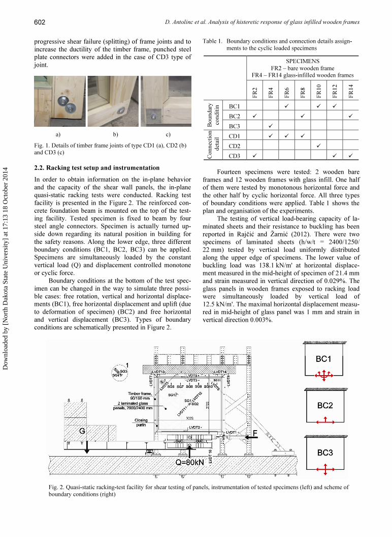
progressive shear failure (splitting) of frame joints and to increase the ductility of the timber frame, punched steel plate connectors were added in the case of CD3 type of joint.
a) b) c) Fig. 1. Details of timber frame joints of type CD1 (a), CD2 (b) and CD3 (c)
2.2. Racking test setup and instrumentation In order to obtain information on the in-plane behavior and the capacity of the shear wall panels, the in-plane quasi-static racking tests were conducted. Racking test facility is presented in the Figure 2. The reinforced con-crete foundation beam is mounted on the top of the test-ing facility. Tested specimen is fixed to beam by four steel angle connectors. Specimen is actually turned up-side down regarding its natural position in building for the safety reasons. Along the lower edge, three different boundary conditions (BC1, BC2, BC3) can be applied. Specimens are simultaneously loaded by the constant vertical load (Q) and displacement controlled monotone or cyclic force.
Boundary conditions at the bottom of the test spec-imen can be changed in the way to simulate three possi-ble cases: free rotation, vertical and horizontal displace-ments (BC1), free horizontal displacement and uplift (due to deformation of specimen) (BC2) and free horizontal and vertical displacement (BC3). Types of boundary conditions are schematically presented in Figure 2.
Table 1. Boundary conditions and connection details assign-ments to the cyclic loaded specimens
SPECIMENS
FR2 – bare wooden frame FR4 – FR14 glass-infilled wooden frames
FR2
FR4
FR6
FR8
FR10
FR12
FR14
Boun
dary
cond
itin BC1 � � �
BC2 � � � BC3 �
Conn
ection
de
tail CD1 � � �
CD2 � CD3 � � �
Fourteen specimens were tested: 2 wooden bare
frames and 12 wooden frames with glass infill. One half of them were tested by monotonous horizontal force and the other half by cyclic horizontal force. All three types of boundary conditions were applied. Table 1 shows the plan and organisation of the experiments.
The testing of vertical load-bearing capacity of la-minated sheets and their resistance to buckling has been reported in Rajčić and Žarnić (2012). There were two specimens of laminated sheets (h/w/t = 2400/1250/ 22 mm) tested by vertical load uniformly distributed along the upper edge of specimens. The lower value of buckling load was 138.1 kN/m' at horizontal displace-ment measured in the mid-height of specimen of 21.4 mm and strain measured in vertical direction of 0.029%. The glass panels in wooden frames exposed to racking load were simultaneously loaded by vertical load of 12.5 kN/m'. The maximal horizontal displacement measu-red in mid-height of glass panel was 1 mm and strain in vertical direction 0.003%.
Fig. 2. Quasi-static racking-test facility for shear testing of panels, instrumentation of tested specimens (left) and scheme of boundary conditions (right)
Dow
nloa
ded
by [
Nor
th D
akot
a St
ate
Uni
vers
ity]
at 1
7:13
18
Oct
ober
201
4
Journal of Civil Engineering and Management, 2014, 20(4): 600–608
603
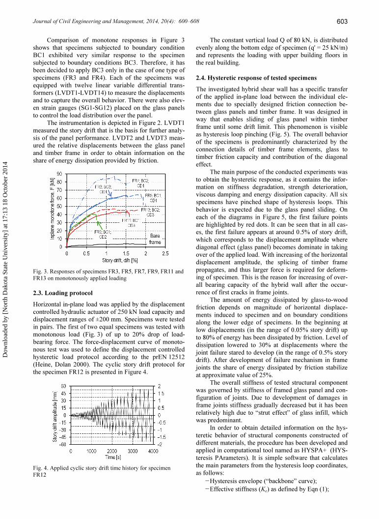
Comparison of monotone responses in Figure 3 shows that specimens subjected to boundary condition BC1 exhibited very similar response to the specimen subjected to boundary conditions BC3. Therefore, it has been decided to apply BC3 only in the case of one type of specimens (FR3 and FR4). Each of the specimens was equipped with twelve linear variable differential trans-formers (LVDT1-LVDT14) to measure the displacements and to capture the overall behavior. There were also elev-en strain gauges (SG1-SG12) placed on the glass panels to control the load distribution over the panel.
The instrumentation is depicted in Figure 2. LVDT1 measured the story drift that is the basis for further analy-sis of the panel performance. LVDT2 and LVDT3 meas-ured the relative displacements between the glass panel and timber frame in order to obtain information on the share of energy dissipation provided by friction.
Fig. 3. Responses of specimens FR3, FR5, FR7, FR9, FR11 and FR13 on monotonously applied loading 2.3. Loading protocol Horizontal in-plane load was applied by the displacement controlled hydraulic actuator of 250 kN load capacity and displacement ranges of ±200 mm. Specimens were tested in pairs. The first of two equal specimens was tested with monotonous load (Fig. 3) of up to 20% drop of load-bearing force. The force-displacement curve of monoto-nous test was used to define the displacement controlled hysteretic load protocol according to the prEN 12512 (Heine, Dolan 2000). The cyclic story drift protocol for the specimen FR12 is presented in Figure 4.
Fig. 4. Applied cyclic story drift time history for specimen FR12
The constant vertical load Q of 80 kN, is distributed evenly along the bottom edge of specimen (q' = 25 kN/m) and represents the loading with upper building floors in the real building.
2.4. Hysteretic response of tested specimens The investigated hybrid shear wall has a specific transfer of the applied in-plane load between the individual ele-ments due to specially designed friction connection be-tween glass panels and timber frame. It was designed in way that enables sliding of glass panel within timber frame until some drift limit. This phenomenon is visible as hysteresis loop pinching (Fig. 5). The overall behavior of the specimens is predominantly characterized by the connection details of timber frame elements, glass to timber friction capacity and contribution of the diagonal effect.
The main purpose of the conducted experiments was to obtain the hysteretic response, as it contains the infor-mation on stiffness degradation, strength deterioration, viscous damping and energy dissipation capacity. All six specimens have pinched shape of hysteresis loops. This behavior is expected due to the glass panel sliding. On each of the diagrams in Figure 5, the first failure points are highlighted by red dots. It can be seen that in all cas-es, the first failure appears at around 0.5% of story drift, which corresponds to the displacement amplitude where diagonal effect (glass panel) becomes dominate in taking over of the applied load. With increasing of the horizontal displacement amplitude, the splicing of timber frame propagates, and thus larger force is required for deform-ing of specimen. This is the reason for increasing of over-all bearing capacity of the hybrid wall after the occur-rence of first cracks in frame joints.
The amount of energy dissipated by glass-to-wood friction depends on magnitude of horizontal displace-ments induced to specimen and on boundary conditions along the lower edge of specimens. In the beginning at low displacements (in the range of 0.05% story drift) up to 80% of energy has been dissipated by friction. Level of dissipation lowered to 30% at displacements where the joint failure stared to develop (in the range of 0.5% story drift). After development of failure mechanism in frame joints the share of energy dissipated by friction stabilize at approximate value of 25%.
The overall stiffness of tested structural component was governed by stiffness of framed glass panel and con-figuration of joints. Due to development of damages in frame joints stiffness gradually decreased but it has been relatively high due to “strut effect” of glass infill, which was predominant.
In order to obtain detailed information on the hys-teretic behavior of structural components constructed of different materials, the procedure has been developed and applied in computational tool named as HYSPA+ (HYS-teresis PArameters). It is simple software that calculates the main parameters from the hysteresis loop coordinates, as follows:
− Hysteresis envelope (“backbone” curve); − Effective stiffness (Ke) as defined by Eqn (1);
Dow
nloa
ded
by [
Nor
th D
akot
a St
ate
Uni
vers
ity]
at 1
7:13
18
Oct
ober
201
4

D. Antolinc et al. Analysis of histeretic response of glass infilled wooden frames
604
− Idealized bilinear envelope as defined in Figure 6; − Ductility factor (µ) as defined by Eqn (1); − Secant stiffness (Ki) associated with each hysteresis
cycle defined by the hysteresis turning point (Fig. 7);
− Parameters of the stiffness degradation curve (n and C), as defined by Eqn (4);
− Strength deterioration defined as lowering of strength at hysteresis turning point due to cyclic re-peating of hysteretic loading;
− Equivalent viscous damping coefficient (ξ) that quantifies the hysteretic energy dissipation. Each of the above listed properties of glass infilled
wooden frames is discussed below except the strength deterioration, because it was of negligible amount.
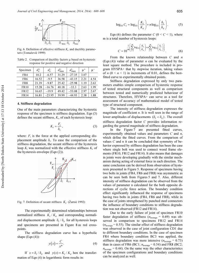
3. Ductility In general, ductility factor (µ) is defined as a ratio be-tween the ultimate displacement and displacement on elastic limit (Eqn (1)). In herein proposed procedure the
parameters of ductility are derived as presented in Fig-ure 6. The idealized bi-linear hysteresis envelope is de-fined by the energy equality principle of surfaces. They are defined by the experimentally obtained hysteresis “backbone” curve and idealized envelope. The idealized envelope is created by the best fitting of bi-liner shape to the “backbone” curve shape. In the case of discussed structural component the value of effective stiffness Ke is defined by the displacement coordinate δcr obtained from “backbone” curve at level of 67% of maximal force (Fmax). Because the response of structural component might be asymmetric, the idealized envelope is calculated separately for each direction of load action (i.e. “positive” and “negative” direction of force action) (Table 2): u
e
δµ = δ ; (1)
max23e
ee cr
FFK = =δ δ
. (2)
Fig. 5. Hysteresis responses of specimens FR4 (a), FR6 (b), FR8 (c), FR10 (d), FR12 (e) and FR14 (f)
Dow
nloa
ded
by [
Nor
th D
akot
a St
ate
Uni
vers
ity]
at 1
7:13
18
Oct
ober
201
4
Journal of Civil Engineering and Management, 2014, 20(4): 600–608
605
Fig. 6. Definition of effective stiffness Ke and ductility parame-ters (Tomaževič 1999)
Table 2. Comparison of ductility factors µ based on hysteresis response for positive and negative direction
Specimen ed + ed − maxd + maxd − +µ µ− FR4 10.2 –6.57 31.29 –27.35 3.07 FR6 16.52 –9.5 36.58 –43.15 2.21 4.54 FR8 21.39 –9.87 25.42 –25.98 1.19 2.63 FR10 15.28 –16.76 40.18 –33.3 2.63 1.99 FR12 16.65 –19.9 49.42 –53.08 2.97 2.67 FR14 16.81 –23.95 39.99 –44.93 2.38 1.88
4. Stiffness degradation One of the main parameters characterizing the hysteretic response of the specimen is stiffness degradation. Eqn (3) defines the secant stiffness, Ki, of each hysteresis loop: i
ii
FK =δ
, (3)
where: Fi is the force at the applied corresponding dis-placement amplitude δi. To ease the comparison of the stiffness degradation, the secant stiffness of the hysteresis loop Ki was normalized with the effective stiffness Ke of the hysteresis envelope (Eqn (2)).
Fig. 7. Definition of secant stiffness iK (Žarnić 1992)
The experimentally determined relationships between
normalized stiffness /i eK K and corresponding normali-zed displacement amplitude /i eδ δ for all hysteresis loops and specimens are presented in Figure 8 as red cross-points.
The stiffness degradation curve has a hyperbolic shape (Eqn (4)): ( ) .
n
Cy x x= (4) If /i ex = δ δ and ( ) / i ey x K K= hen the transfor-
mation of Eqn (4) in logarithmic form results in:
10 10 10log log logi ii
e e
KC nK
δ= + δ . (5)
Eqn (6) defines the parameter C (0 < C < 1), where m is a total number of hysteresis loops:
10 101 1
1 log log10
m mi i
e ei i
K nm KC = =
δ + δ =∑ ∑ . (6)
From the known relationship between C and n (Eqn (4)) value of parameter n can be evaluated by the least square method. The procedure is included in pro-gram HYSPA+ that by stepwise iteration, taking values of n (0 < n < 1) in increments of 0.01, defines the best-fitted curve to experimentally obtained points.
Stiffness degradation expressed by only two para-meters enables simple comparison of hysteretic response of tested structural components as well as comparison between tested and numerically predicted behaviour of structures. Therefore, HYSPA+ can serve as a tool for assessment of accuracy of mathematical model of tested type of structural component.
The intensity of stiffness degradation expresses the magnitude of coefficient n. It is well seen in the range of lower amplitudes of displacements ( )i eδ < δ . The overall stiffness degradation factor C provides information re-garding the general magnitude of stiffness degradation.
In the Figure 7 are presented fitted curves, experimentally obtained values and parameters C and n, which define the fitted curves. From the comparison of values C and n it can be concluded that symmetry of be-havior expressed by stiffness degradation has been the case where single bolt was used to connect wood frame ele-ments (FR10, FR12 and FR14). It also means that damages in joints were developing gradually with the similar mech-anism during acting of external force in each direction. The same conclusion can be derived from observation of hyste-resis presented in Figure 5. Response of specimens having two bolts in joints (FR4, FR6 and FR8) was asymmetric as can be seen both from Figures 5 and 7. Also, different intensity of stiffness degradation can be observed from the values of parameter n calculated for the both opposite di-rections of cyclic force action. The boundary condition effect significantly influenced the response of specimens having two bolts in joints (FR4, FR6 and FR8), while in the case of joints strengthened by punched steel connectors the influence of boundary conditions to stiffness degrada-tion was not observed (FR12 and FR14).
Due to the early failure of joint of specimen FR10 faster degradation of stiffness (naverage = 0.69) was ob-served in comparison to specimens FR12 and FR14 (naverage = 0.55). The similar effect of stiffness degradation was observed in the case of joint configuration CD1 due to different boundary conditions. In the case of specimen FR4 where boundary condition BC3 was applied, the stiffness degradation was more intensive (naverage = 0.73) than in cases of FR6 (BC1; naverage = 0.54) and FR8 (BC2; naverage = 0.44). On the same way the other characteristics of the specimen configurations and boundary conditions can be analyzed as well.
Dow
nloa
ded
by [
Nor
th D
akot
a St
ate
Uni
vers
ity]
at 1
7:13
18
Oct
ober
201
4

D. Antolinc et al. Analysis of histeretic response of glass infilled wooden frames
606
5. Equivalent viscous damping The equivalent viscous damping coefficient ξ is quantify-ing the hysteresis response of structural components, and as such, it is one of the key indicators describing their behavior. It is defined by expression:
( )max min
1 12 2 22 2
D D DE EE p n
E E EE E E K u K u
+ −ξ = = =π π + π +
.
(7) In above equation DE stands for the dissipated en-
ergy in hysteresis loop, EE for the elastic strain energy, EE+ and EE− for the elastic strain energy in positive and
negative direction of force action, pK and nK for secant
stiffness of the loop in positive and negative direction, and maxd and mind for the maximum and minimum displacements of the considered loop. The parameters employed in the Eqn (7) are graphically presented in Figure 9 below.
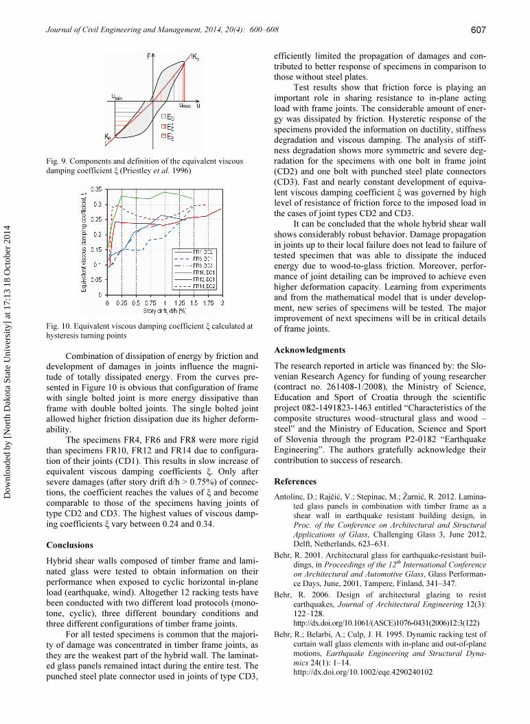
Equivalent viscous damping ξ calculated at hystere-sis turning points is presented in Figure 10. For speci-mens FR10, FR12 and FR14, it can be observed that al-most constant maximum value of ξ is recorded at relatively small displacements, which can be explained with influence of glass-to-wood friction dissipation of energy at lower displacement amplitudes. In the case of FR4, FR8 and FR8 energy was dissipated due to gradual development of damages in frame joints and by friction along the frame-to-glass contact.
Fig. 8. Normalised stiffness degradation with calculated stiffness degradation characteristic factors C and n for specimens FR4 (a), FR6 (b), FR8 (c), FR10 (d), FR12 (e) and FR14 (f)
Dow
nloa
ded
by [
Nor
th D
akot
a St
ate
Uni
vers
ity]
at 1
7:13
18
Oct
ober
201
4
Journal of Civil Engineering and Management, 2014, 20(4): 600–608
607
Fig. 9. Components and definition of the equivalent viscous damping coefficient ξ (Priestley et al. 1996)
Fig. 10. Equivalent viscous damping coefficient ξ calculated at hysteresis turning points
Combination of dissipation of energy by friction and
development of damages in joints influence the magni-tude of totally dissipated energy. From the curves pre-sented in Figure 10 is obvious that configuration of frame with single bolted joint is more energy dissipative than frame with double bolted joints. The single bolted joint allowed higher friction dissipation due its higher deform-ability.
The specimens FR4, FR6 and FR8 were more rigid than specimens FR10, FR12 and FR14 due to configura-tion of their joints (CD1). This results in slow increase of equivalent viscous damping coefficients ξ. Only after severe damages (after story drift d/h > 0.75%) of connec-tions, the coefficient reaches the values of ξ and become comparable to those of the specimens having joints of type CD2 and CD3. The highest values of viscous damp-ing coefficients ξ vary between 0.24 and 0.34.
Conclusions Hybrid shear walls composed of timber frame and lami-nated glass were tested to obtain information on their performance when exposed to cyclic horizontal in-plane load (earthquake, wind). Altogether 12 racking tests have been conducted with two different load protocols (mono-tone, cyclic), three different boundary conditions and three different configurations of timber frame joints.
For all tested specimens is common that the majori-ty of damage was concentrated in timber frame joints, as they are the weakest part of the hybrid wall. The laminat-ed glass panels remained intact during the entire test. The punched steel plate connector used in joints of type CD3,
efficiently limited the propagation of damages and con-tributed to better response of specimens in comparison to those without steel plates.
Test results show that friction force is playing an important role in sharing resistance to in-plane acting load with frame joints. The considerable amount of ener-gy was dissipated by friction. Hysteretic response of the specimens provided the information on ductility, stiffness degradation and viscous damping. The analysis of stiff-ness degradation shows more symmetric and severe deg-radation for the specimens with one bolt in frame joint (CD2) and one bolt with punched steel plate connectors (CD3). Fast and nearly constant development of equiva-lent viscous damping coefficient ξ was governed by high level of resistance of friction force to the imposed load in the cases of joint types CD2 and CD3.
It can be concluded that the whole hybrid shear wall shows considerably robust behavior. Damage propagation in joints up to their local failure does not lead to failure of tested specimen that was able to dissipate the induced energy due to wood-to-glass friction. Moreover, perfor-mance of joint detailing can be improved to achieve even higher deformation capacity. Learning from experiments and from the mathematical model that is under develop-ment, new series of specimens will be tested. The major improvement of next specimens will be in critical details of frame joints.
Acknowledgments The research reported in article was financed by: the Slo-venian Research Agency for funding of young researcher (contract no. 261408-1/2008), the Ministry of Science, Education and Sport of Croatia through the scientific project 082-1491823-1463 entitled “Characteristics of the composite structures wood–structural glass and wood – steel” and the Ministry of Education, Science and Sport of Slovenia through the program P2-0182 “Earthquake Engineering”. The authors gratefully acknowledge their contribution to success of research.
References Antolinc, D.; Rajčić, V.; Stepinac, M.; Žarnić, R. 2012. Lamina-
ted glass panels in combination with timber frame as a shear wall in earthquake resistant building design, in Proc. of the Conference on Architectural and Structural Applications of Glass, Challenging Glass 3, June 2012, Delft, Netherlands, 623–631.
Behr, R. 2001. Architectural glass for earthquake-resistant buil-dings, in Proceedings of the 12th International Conference on Architectural and Automotive Glass, Glass Performan-ce Days, June, 2001, Tampere, Finland, 341–347.
Behr, R. 2006. Design of architectural glazing to resist earthquakes, Journal of Architectural Engineering 12(3): 122–128. http://dx.doi.org/10.1061/(ASCE)1076-0431(2006)12:3(122)
Behr, R.; Belarbi, A.; Culp, J. H. 1995. Dynamic racking test of curtain wall glass elements with in-plane and out-of-plane motions, Earthquake Engineering and Structural Dyna-mics 24(1): 1–14. http://dx.doi.org/10.1002/eqe.4290240102
Dow
nloa
ded
by [
Nor
th D
akot
a St
ate
Uni
vers
ity]
at 1
7:13
18
Oct
ober
201
4

D. Antolinc et al. Analysis of histeretic response of glass infilled wooden frames
608
Eurocode 8: Design of structures for earthquake resistance. Part 1: General rules, seismic actions and rules for buil-dings. European pre-standard, ENV 1998-1, CEN, Brus-sels, 2008.
Eva, C.; Hutchinson, T. C. 2011. Experimental evaluation of the in-plane seismic behaviour of storefront window systems, Earthquake Spectra 27(4): 997–1021. http://dx.doi.org/10.1193/1.3651407
Freitag, C.; Woerner, J-D. 2009. Glass as structural bracings – shear capacity of mechanically pre-stressed windowpanes, in Proceedings of the 11th International Conference on Architectural and Automotive Glass, Glass Performance Days, June, 2009, Tampere, Finland, 329–333.
Heine, C. P.; Dolan, J. D. 2000. Cyclic response of multiple bolted connections, in World Conference on Timber Engi-neering, 2000, Whistler Resort, British Columbia, Cana-da. 7 p.
Hutchinson, T. C.; Jian, Z.; Eva, C. 2011. Development of a drift protocol for seismic performance evaluation conside-ring damage index concept, Earthquake Spectra 27(4): 1049–1076. http://dx.doi.org/10.1193/1.3652707
Huveners, E. 2009. Circumferentially adhesive bonded glass panes for bracing steel frames in facades: PhD Thesis. TU Eindhoven, Netherlands.
Kaklauskas, A.; Zavadskas, E. K.; Raslanas, S. 2005. Multiva-riant design and multiple criteria analysis of building re-furbishments, Energy and Buildings 37(4): 361–372. http://dx.doi.org/10.1016/j.enbuild.2004.07.005
McBean, P. 2005. Drift intolerant facade systems and flexible shear walls. Do we have a problem?, in Proc. of the An-nual Technical Conference of the Australian Earthquake Engineering Society, 2005, Albury, Australia, 1–8.
Memari, A. M.; Shirazi, A.; Kremer, P. A. 2007. Static finite element analysis of architectural glass curtain walls under in-plane loads and corresponding full-scale test, Structural Engineering and Mechanics 25(4): 365–382. http://dx.doi.org/10.12989/sem.2007.25.4.365
Močibob, D. 2008. Glass panel under shear loading – Use of glass envelopes in building stabilization: PhD Thesis. EPFL, Switzerland.
Niedermaier, P. 2003. Shear-strength of glass panel elements in combination with timber frame constructions, in Proc. of the 8th International Conference on Architectural and Automotive Glass, Glass Performance Days, June, 2003, Tampere, Finland, 262–264.
Pantelides, C. P.; Truman, K. Z.; Behr, R. A.; Belarbi, A. 1996. Development of a loading history for seismic testing of architectural glass in a shop-front wall system, Enginee-ring Structures 18(12): 917–935. http://dx.doi.org/10.1016/0141-0296(95)00224-3
Priestley, M. J. N.; Seible, F.; Calvi, G. M. 1996. Seismic design and retrofit of bridges. John Wiley & Sons, Inc. 721 p. http://dx.doi.org/10.1002/9780470172858
Rajčić, V.; Žarnić, R. 2012. Racking performance of wood-framed glass panels, in Quenneville, P. (Ed.). WCTE 2012: The Future of Timber Engineering: Final Papers. Auckland: WCTE, 57–62.
Sivanerupan, S.; Wilson, J. L.; Gad, E. F. 2008. Drift perfor-mance of façade systems, in Proc. of the Earthquake En-gineering in Australia Conference, November, 2008, Bal-larat, Victoria, Australia, 21–23.
Sivanerupan, S.; Wilson, J. L.; Gad, E. F.; Lam, N. T. K. 2011. Structural analysis and design of glazed curtain wall sys-tems, Australian Journal of Structural Engineering 2(1): 57–67.
Sung, W.; Shih, M.; Zhao, Y. 2010. Energy dissipation behav-iors and seismic reduction performance of a proposed ve-locity and displacement dependent hydraulic damper (VDHD), Journal of Civil Engineering and Management 16(3): 428–438. http://dx.doi.org/10.3846/jcem.2010.49
Tomaževič, M. 1999. Earthquake-resistant design of masonry buildings. Imperial College Press. 268 p. http://dx.doi.org/10.1142/p055
Žarnić, R. 1992. Neelastični odziv armiranobetonskih okvirov z zidanimi polnili na potresno obtežbo [Inelastic response of reinforced concrete frames with masonry filler on the seismic load]: PhD Thesis. University of Ljubljana, Facul-ty of Civil and Geodetic Engineering, Slovenia. 195 p.
Žarnić, R.; Tsionis, G.; Gutierrez, E.; Pinto, A.; Geradin, M.; Dimova, S. 2007. Purpose and justification for new de-sign standards regarding the use of glass products in civil engineering works: support to the implementation, har-monization and further development of the Eurocodes. JCR Scientific and Technical Reports, EUR 22856 EN. 1st ed. Luxembourg: Office for Official Publications of the European Communities: Joint Research Centre Euro-pean Commission. 30 p.
David ANTOLINC. PhD, Teaching Assistant at the Faculty of Civil and Geodetic Engineering at the University of Ljubljana. Publications: 9 articles about structural glass and computational modelling of FRP structures. Research inter-ests: structural glass in earthquake resistant buildings, composite materials and resistance of buildings on blast loads. Vlatka RAJČIĆ. PhD, Professor at the Faculty of Civil Engineering at the University of Zagreb. Participating in many international projects, lately was dissemination leader of recent FP7 projects EU-CHIC, WP leader in FP7 SMooHS, FP7 Climate for Culture. She is a coordinator of the Horizontal Issue: Ethics, Education and Training in Cultural Heritage of the activities of Focus Area Cultural Heritage (FACH) within the European Construction Technology Platform (ECTP). Publications: 5 university textbooks and more than 100 articles in books, journals and conference proceedings. Research interests: development of hybrid structural elements of wood and emerging materials (structural glass, steel, cross-laminated wood, FRP), design of contemporary large-span timber structures, research in structural aspects of cultural her-itage buildings. Roko ŽARNIĆ. PhD, Professor at the Faculty of Civil and Geodetic Engineering at the University of Ljubljana. Partici-pating in 31 international projects (EU FP4 to FP7, EUREKA and COST), coordinating the recent EU FP7 Project EU-CHIC, Coordinator of the Focus Area Cultural Heritage (FACH) within the ECTP. Publications: 2 university textbooks and more than 260 articles in books, journals and conference proceedings. Research interests: development of structural elements of wood and emerging materials (FRP, laminated glass, laminated wood), research in earthquake strengthening of masonry and reinforced concrete structures, research in material and structural aspects of cultural heritage buildings and development of strategies for preservation and preventive conservation of heritage buildings and objects.
Dow
nloa
ded
by [
Nor
th D
akot
a St
ate
Uni
vers
ity]
at 1
7:13
18
Oct
ober
201
4