analysis of distributed flexible ac transmission system devices for power system … ·...
TRANSCRIPT

Volume 2 | Special Issue 01 | October 2016| ISSN: 2455-3778| www.ijmtst.com 189
Proceedings of National Conference on Computing, Electrical, Electronics and Sustainable Energy Systems
Analysis of Distributed Flexible AC
Transmission System Devices for
Power System Control
M. Kaveri1 | M. John Srinivasa Rao2
1PG Scholar, Department of EEE, Godavari Institute of Engineering and Technology, Rajahmundry, Andhra Pradesh, India. 2Assistant Professor, Department of EEE, Godavari Institute of Engineering and Technology, Rajahmundry, Andhra Pradesh, India.
ABSTRACT
This paper reviews the importance of a flexible ac distribution system device for microgrid
applications. The device aims to improve the power quality and reliability of the overall power
distribution system that the Microgrid is connected to. Extended Kalman filters are also studied for
frequency tracking and to extract the harmonic spectra of the grid voltage and the load currents in the
microgrid. Also this paper high lights on DG grouping in order to harmonize the investment of assets,
the quality of power supply and the cooperation with the existing power grid.
KEYWORDS: Extended Kalman filter, microgrid, Harmonized grouping, power quality, Security
enhancement
Copyright © 2016 International Journal for Modern Trends in Science and Technology
All rights reserved.
I. INTRODUCTION
For traditional power distribution system, the
concept of microgrid has offered consumers a
reliability and reduction in total energy losses
and it has become a promising
alternative.[1],[2] While connecting microgrid to
the distribution grid, the impact of power
quality (PQ) problem on the overall power
system performance has to be considered.
These PQ problem includes voltage and
frequency deviation in the grid voltage and
harmonics in the voltage and load currents. To
mitigate these problem various equipments
such as active filters[3],[4], uninterrupted
power supplies[5],[6], dynamic voltage
restorers,[7],[8] and UPQC [9] are usually
installed by the consumers to protect their
loads and system against PQ disturbances in
distribution network. But these devices are
installed at the consumer sides and the PQ
problems that they are capable to handle are
usually limited. In this paper a flexible ac
distribution system devices are of series and
shunt voltage source inverters (VSIs) for the
microgrid. The device is installed at the point of
common coupling (PCC) of the distribution grid
that the microgrid and other electrical loads are
connected to. Also, during islanded operation of
the microgrid, the device can provide real and
reactive power to the microgrid. The device will
accomplish the following tasks simultaneously:
1. Compensating for harmonics in the grid voltage and load currents;
2. Real and reactive power control for load sharing during peak periods and power factor correction at the grid side;
3. Maintaining PQ despite slight voltage and frequency variations in the grid voltage; and
4. Momentarily dispatching real and reactive power to the microgrid when it becomes islanded.
II. SYSTEM ARCHITECTURE
The configuration of the microgrid
considered in this paper for implementation of
the flexible ac distribution system device is
shown in Fig. 1. microgrid consists of three
radial feeders (1, 2 and 3) where feeders 1 and
3 are each connected to a distributed
Volume 2 | Special Issue 01 | October 2016| ISSN: 2455-3778| www.ijmtst.com 190
Proceedings of National Conference on Computing, Electrical, Electronics and Sustainable Energy Systems
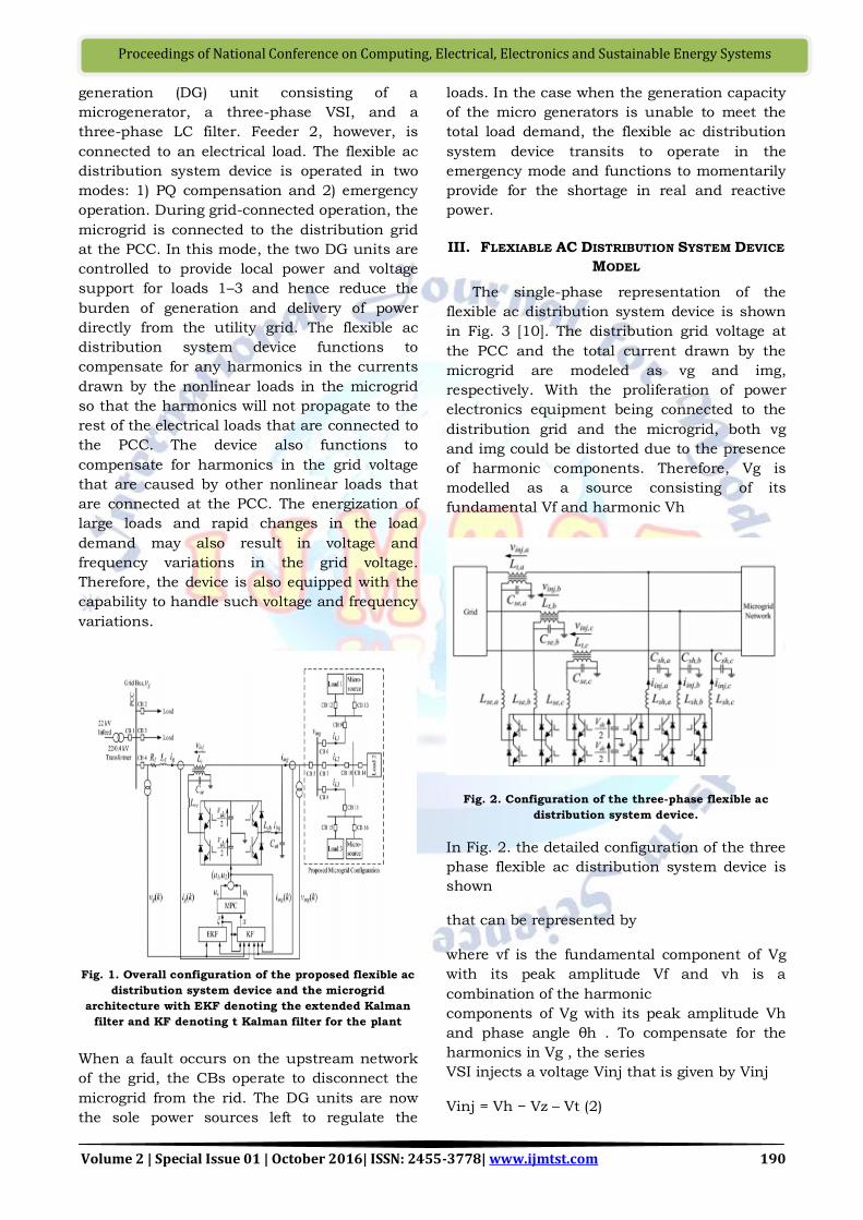
generation (DG) unit consisting of a
microgenerator, a three-phase VSI, and a
three-phase LC filter. Feeder 2, however, is
connected to an electrical load. The flexible ac
distribution system device is operated in two
modes: 1) PQ compensation and 2) emergency
operation. During grid-connected operation, the
microgrid is connected to the distribution grid
at the PCC. In this mode, the two DG units are
controlled to provide local power and voltage
support for loads 1–3 and hence reduce the
burden of generation and delivery of power
directly from the utility grid. The flexible ac
distribution system device functions to
compensate for any harmonics in the currents
drawn by the nonlinear loads in the microgrid
so that the harmonics will not propagate to the
rest of the electrical loads that are connected to
the PCC. The device also functions to
compensate for harmonics in the grid voltage
that are caused by other nonlinear loads that
are connected at the PCC. The energization of
large loads and rapid changes in the load
demand may also result in voltage and
frequency variations in the grid voltage.
Therefore, the device is also equipped with the
capability to handle such voltage and frequency
variations.
Fig. 1. Overall configuration of the proposed flexible ac
distribution system device and the microgrid
architecture with EKF denoting the extended Kalman
filter and KF denoting t Kalman filter for the plant
When a fault occurs on the upstream network
of the grid, the CBs operate to disconnect the
microgrid from the rid. The DG units are now
the sole power sources left to regulate the
loads. In the case when the generation capacity
of the micro generators is unable to meet the
total load demand, the flexible ac distribution
system device transits to operate in the
emergency mode and functions to momentarily
provide for the shortage in real and reactive
power.
III. FLEXIABLE AC DISTRIBUTION SYSTEM DEVICE
MODEL
The single-phase representation of the
flexible ac distribution system device is shown
in Fig. 3 [10]. The distribution grid voltage at
the PCC and the total current drawn by the
microgrid are modeled as vg and img,
respectively. With the proliferation of power
electronics equipment being connected to the
distribution grid and the microgrid, both vg
and img could be distorted due to the presence
of harmonic components. Therefore, Vg is
modelled as a source consisting of its
fundamental Vf and harmonic Vh
Fig. 2. Configuration of the three-phase flexible ac
distribution system device.
In Fig. 2. the detailed configuration of the three
phase flexible ac distribution system device is
shown
that can be represented by
where vf is the fundamental component of Vg
with its peak amplitude Vf and vh is a
combination of the harmonic
components of Vg with its peak amplitude Vh
and phase angle θh . To compensate for the
harmonics in Vg , the series
VSI injects a voltage Vinj that is given by Vinj
Vinj = Vh − Vz – Vt (2)

Volume 2 | Special Issue 01 | October 2016| ISSN: 2455-3778| www.ijmtst.com 191
Proceedings of National Conference on Computing, Electrical, Electronics and Sustainable Energy Systems
Similarly, img is also modelled as two
components consisting of fundamental if and
harmonic ih with their peak amplitudes If and
Ih, respectively and is represented by
where ϕf and ϕh are the respective phase angles
of the fundamental and harmonic components
of img, and if,p and if,q are the instantaneous
fundamental phase and quadrature
components of img. To achieve unity power
factor at the grid side, compensate for the
harmonics in the microgrid current and achieve
load sharing concurrently, the shunt VSI
injects a current iinj that is given by
iinj = (if,p − ig) + if,q + ih + iCsh
where ig is the grid current. The switched
voltage across the series and shunt VSIs of the
flexible ac distribution system device are
represented by u1 (Vdc/2) and u2 (Vdc/2) ,
respectively. To eliminate the high switching
frequency components generated by the series
and shunt VSIs, two second-order low-pass
interfacing filters which are represented by Lse,
Cse, Lsh , and Csh are incorporated. The losses
of the series and shunt VSIs are modeled as
Rse and Rsh , respectively.
Fig. 3. Single-phase representation of the flexible ac
distribution system device.
IV. PHOTOVOLTAIC ARRAY
Photovoltaic (PV) is a method of generating
electrical power by converting solar radiation
into direct current electricity using
semiconductors that exhibit the photovoltaic
effect. Photovoltaic power generation employs
solar panels comprising a number of cells
containing a photovoltaic material. Materials
presently used for photovoltaic include mono
crystalline silicon, polycrystalline silicon,
amorphous silicon, cadmium telluride, and
copper indium serenade/sulfide. Due to the
growing demand for renewable energy sources,
the manufacturing of solar cells and
photovoltaic arrays has advanced considerably
in recent years
Fig.4 PV effect converts the photon energy into voltage
across the pn junction
Fig 4:The photovoltaic effect is different in that
the generated electrons are transferred between
different bands (i.e. from the valence to
conduction bands) within the material,
resulting in the buildup of a voltage between
two electrodes. In most photovoltaic
applications the radiation is sunlight and for
this reason the devices are known as solar
cells. In the case of a p-n junction solar cell,
illumination of the material results in the
generation of an electric current as excited
electrons and the remaining holes are swept in
different directions by the built-in electric field
of the depletion region.
V. MPPT CONTROLLER
Maximum power point tracker (or MPPT) is
a high efficiency DC to DC converter that
presents an optimal electrical load to a solar
panel or array and produces a voltage suitable
for the load. PV cells have a single operating
point where the values of the current (I) and
Voltage (V) of the cell result in a maximum
power output. These values correspond to a
particular load resistance, which is equal to V/I
as specified by Ohm's Law. A PV cell has an
exponential relationship between current and
voltage, and the maximum power point (MPP)
occurs at the knee of the curve, where the
resistance is equal to the negative of the
differential resistance (V/I = -dV/dI). Maximum
power point trackers utilize some type of
control circuit or logic to search for this point
and thus to allow the converter circuit to

Volume 2 | Special Issue 01 | October 2016| ISSN: 2455-3778| www.ijmtst.com 192
Proceedings of National Conference on Computing, Electrical, Electronics and Sustainable Energy Systems
extract the maximum power available from a
cell. Traditional solar inverters perform MPPT
for an entire array as a whole. In such systems
the same current, dictated by the inverter,
flows though all panels in the string. But
because different panels have different IV
curves, i.e. different MPPs (due to
manufacturing tolerance, partial shading, etc.)
this architecture means some panels will be
performing below their MPP, resulting in the
loss of energy. Some companies (see power
optimizer) are now placing peak power point
converters into individual panels, allowing each
to operate at peak efficiency despite uneven
shading, soiling or electrical mismatch.
VI. HYBRID SOURCE FOR DC LINK VOLTAGE
The proposed source for the dc-link voltage
of the flexible ac distribution system device
consists of a PV array and a battery as shown
in Fig. 5. The PV array and the battery are
connected to the VSI of the device through a
boost converter and a buck–boost converter,
respectively, to facilitate charging and
discharging operations for the battery and
to regulate the dc-link voltage at the desired
level. To maintain the dc-link at the reference
voltage V*dc/2, a dual loop control scheme in
[14], which consists of an outer voltage loop
and an inner current loop for the bidirectional
converter, is implemented to compensate for
the variation in the output voltage Vdc/2 of the
dc/dc boost converter. In this section, the
operation of the PV/battery system is briefly
explained. When there is ample sunlight, the
PV array is controlled by the dc/dc boost
converter to operate in the MPPT mode to
deliver its maximum dc power Ppv at Vdc/2,
which induces a voltage error (V ∗ dc/2 −
Vdc/2) at the dc-link. The error is passed to a
PI controller, which produces a reference
battery current i∗ b for the inner current loop
to operate the battery in either the charging
mode for a positive error or discharging mode
for a negative error. When the battery is in the
charging mode, the bidirectional converter
operates as a buck converter by turning switch
Q3a OFF and applying the control signal from
the controller to switch Q2a ON as shown in
Fig. 6. Conversely, when the battery is in the
discharging mode, the bidirectional converter
operates as a boost converter by turning switch
Q2a OFF and applying the control signal from
the controller to switch Q3a ON as shown in
Fig. 7. Figs. 6 and 7 illustrate the charging and
discharging operations of Battery 1, so as to
maintain the upper dc-link voltage at a desired
value. The same charging and discharging
operations are applied to Battery 2 such that
the dc-link voltages for both the upper and
lower dc-link capacitors are maintained at V
∗ dc/2. When the PV array is subject to
prolonged period of sunless hours and the
state-of-charge of the battery falls below a
preset limit, a selfcharging technique from the
grid can be incorporated
Fig.6:Proposed PV/battery system for the device.

Volume 2 | Special Issue 01 | October 2016| ISSN: 2455-3778| www.ijmtst.com 193
Proceedings of National Conference on Computing, Electrical, Electronics and Sustainable Energy Systems
VII. HARMONIZED GROUPING OF NATURAL
RESOURCE DG AND SECURITY
ENHANCEMENT
Output of the natural resource DG, such as
the wind plant and the PV plant, is
considerably fluctuated with the weather
condition. The kW-balance of the total DG
output and the demand has to be continuously
maintained even in lots of uncertain factors.
The battery can be used for absorbing the
mismatch energy of the supply-demand
balancing in the DG group. From the
economical viewpoint, the harmonized grouping
can be realized by minimizing the asset
investment of the natural resource DG plants
and the battery subject to the engineering
constraints. The O&M cost, the quality of
supply power, the environmental impact and
other factors would be included for evaluating
the performance of DG grouping. In the model
analysis of the harmonized DG grouping, we
assume that the kW-balance in the DG group
is realized on the average value basis. Total
kW-fluctuation of the natural resource plant
has to be regulated by the adjustable power of
the battery and the spinning reserve from the
utility in order to maintain the specified quality
of power supply.
Fig 7 Typical Grouping of DG
VIII. SIMULATION RESULTS
Fig8: Simulation implementation of Micro Grid
This simulation diagram for this system is
shown in fig8: And results are verified under
two cases.
Case 1: with PI Controller In this the
conventional PI controller is used for series and
shunt controllers. The obtained results are
shown in below Figures
Fig8:Simulation result for Feeder currents 1, 2 and 3
Fig8:shows the simulation results for the
system feeder currents under without and with
compensation.
Fig9:Simulation result for Grid, Series Converter and
Micro-Grid Voltage
Fig9: shows the simulation results for the
system micro grid voltage under without and
with compensation
Figure 10:Simulation result for Grid, Series Converter
and Micro-Grid Current

Volume 2 | Special Issue 01 | October 2016| ISSN: 2455-3778| www.ijmtst.com 194
Proceedings of National Conference on Computing, Electrical, Electronics and Sustainable Energy Systems
Figure 10:shows the simulation results for the
system Micro-Grid Currents under without and
with compensation
Fig 11: Simulation result for Active Power under
Islanded condition
Fig11: shows the simulation result for the
active and reactive powers under Islanded
condition. In this case we consider the islanded
condition at time t=0.17sec and at that the grid
is disconnected from the system. Case 1.with PI
controller
Fig12: shows the total harmonic distortion values
under with PI controller.
IX. CONCLUSION
In this paper, a flexible ac distribution
system device for microgrid applications has
been presented. In this paper, the solution
integrates EKF into the control design for
frequency tracking and to extract the harmonic
spectra of the grid voltage and the load
currents. The device is installed at the PCC
that the microgrid and other electrical
networks are connected to and is designed to
tackle a wide range of PQ issues. It also
operates as a DG unit to perform load sharing
when the cost of generation from the grid is
high such that peak shaving is achieved and
also during islanded operation of the microgrid.
The conclusion is device can handle a wide
range of PQ issues, thus increasing the overall
PQ and reliability of the microgrid. However,
the proposed design concept still needs further
validation by experimental studies because
measurement errors due to inaccuracies of the
voltage and current sensors, and modeling
errors due to variations in system parameters
could affect the performance of the device in
practical implementation. The security
enhancement of multiple distributed generation
(DG) by the harmonized grouping.
REFERENCES
[1] F.Wang, J. L.Duarte, and M.A.M. Hendrix, "Grid-
Interfacing Converter Systems with Enhanced
Voltage Quality for Microgrid Application
Concept and Implementation" IEEE 2011.
Volume: 26, Issue: 12
[2] F.Wang, J.L.Duarte, and M.A.M.Hendrix, “Pliant
active and reactive power control for grid-
interactive converters under unbalanced voltage
dips,” IEEE Transactions on Power Electronics,
in press, 2010. Volume: 26, Issue: 5.
[3] H.Farhangi, “The path of the smart grid,” IEEE
Power Energy Mag.,vol. 8, no. 1, pp. 18-28,
Jan./Feb. 2010
[4] H.Fujita, and H.Akagi, “The unified power
quality conditioner: the integration of series- and
shunt-active filters,” IEEE Trans. Power
Electron., vol. 13, no. 2, pp. 315-322, Mar. 1998
[5] S.Silva, P.F.Donoso-Garcia, P.C.Cortizo, and
P.F.Seixas, “A three phase line-interactive ups
system implementation with series-parallel
active power-line conditioning capabilities,”
IEEE Trans. Ind. Appl., vol. 38, no. 6, pp. 1581-
1590, Nov./Dec. 2002.
[6] B.Han, B.Bae, H.Kim, and S.Baek, “Combined
operation of unified power-quality conditioner
with distributed generation,” IEEE Trans. Power
Delivery, vol. 21, no. 1, pp. 330-338, Jan. 2006.
[7] H.Tao, “Integration of sustainable energy
sources through power electronic converters in
small distributed electricity generation systems,”
PhD dissertation, Eindhoven university of
technology, 2008.
[8] J.M.Guerrero, L.G.D.Vicuna, J.Matas,
M.Castilla, and J.Miret, “A wireless controller to
enhance dynamic performance of parallel
inverters in distributed generation systems,”
IEEE Trans. Power Electron., vol. 19, no. 5, pp.
1205-1213, Sept. 2004.
[9] Y.W.Li, and C.-N.Kao, “An accurate power
control strategies for power-electronic-interfaced
distributed generation units operating in a low-
voltage multi bus micro grid,” IEEE Trans. Power
Electron., vol. 24, no. 12, pp. 2977-2988, Dec.
2009.
[10] F.Wang, J.LDuarte, and M.A.M.Hendrix,
“Reconfiguring grid interfacing converters for
power quality improvement,” in Proc. IEEE

Volume 2 | Special Issue 01 | October 2016| ISSN: 2455-3778| www.ijmtst.com 195
Proceedings of National Conference on Computing, Electrical, Electronics and Sustainable Energy Systems
Benelux Young Researchers Symposium \ in
Electrical Power Engineering, 2008, pp. 1-6.
[11] Sungwoo Bae, Alexis Kwasinski “Dynamic
Modeling and Operation Strategy for a Microgrid
with Wind and Photovoltaic Resources” IEEE
2012 TRANSACTIONS ON SMART GRID Volume:
3, Issue: 4
[12] L.H.Tey, Member, IEEE, P.L.So, Senior
Member, IEEE, and Y.C.Chu, Member, IEEE
“Improvement of Power Quality Using Adaptive
Shunt Active Filter”IEEE TRANSACTIONS ON
POWER DELIVERY, VOL. 20, NO. 2, APRIL2005.