modicon tm5 / tm7 flexible system - system planning and ......eio0000000426.03 modicon tm5 / tm7...
TRANSCRIPT

Modicon TM5 / TM7 Flexible System
EIO0000000426 04/2012
EIO
0000
0004
26.0
3
www.schneider-electric.com
Modicon TM5 / TM7 Flexible SystemSystem Planning and Installation Guide
04/2012

The information provided in this documentation contains general descriptions and/or technical characteristics of the performance of the products contained herein. This documentation is not intended as a substitute for and is not to be used for determining suitability or reliability of these products for specific user applications. It is the duty of any such user or integrator to perform the appropriate and complete risk analysis, evaluation and testing of the products with respect to the relevant specific application or use thereof. Neither Schneider Electric nor any of its affiliates or subsidiaries shall be responsible or liable for misuse of the information contained herein. If you have any suggestions for improvements or amendments or have found errors in this publication, please notify us.
No part of this document may be reproduced in any form or by any means, electronic or mechanical, including photocopying, without express written permission of Schneider Electric.
All pertinent state, regional, and local safety regulations must be observed when installing and using this product. For reasons of safety and to help ensure compliance with documented system data, only the manufacturer should perform repairs to components.
When devices are used for applications with technical safety requirements, the relevant instructions must be followed.
Failure to use Schneider Electric software or approved software with our hardware products may result in injury, harm, or improper operating results.
Failure to observe this information can result in injury or equipment damage.
© 2012 Schneider Electric. All rights reserved.
2 EIO0000000426 04/2012

Table of Contents
Safety Information . . . . . . . . . . . . . . . . . . . . . . . . . . . . . . 7About the Book . . . . . . . . . . . . . . . . . . . . . . . . . . . . . . . . . 9
Part I Introduction to the TM5 / TM7 System . . . . . . . . . . . 15Chapter 1 Basics of the TM5 / TM7 System . . . . . . . . . . . . . . . . . . . 17
TM5 / TM7 Controller System Architecture . . . . . . . . . . . . . . . . . . . . . . . . 18TM5 / TM7 Distributed I/Os Architecture . . . . . . . . . . . . . . . . . . . . . . . . . . 21 Color Coding of the TM5 System . . . . . . . . . . . . . . . . . . . . . . . . . . . . . . . 24
Chapter 2 Description of the TM5 System . . . . . . . . . . . . . . . . . . . . 27Controller Description . . . . . . . . . . . . . . . . . . . . . . . . . . . . . . . . . . . . . . . . 28Field Bus Interface Description . . . . . . . . . . . . . . . . . . . . . . . . . . . . . . . . . 34Compact I/O Description . . . . . . . . . . . . . . . . . . . . . . . . . . . . . . . . . . . . . . 39Slice Description . . . . . . . . . . . . . . . . . . . . . . . . . . . . . . . . . . . . . . . . . . . . 43Accessories . . . . . . . . . . . . . . . . . . . . . . . . . . . . . . . . . . . . . . . . . . . . . . . . 47
Chapter 3 Description of the TM7 System . . . . . . . . . . . . . . . . . . . . 53Field Bus Interface I/O Block Description . . . . . . . . . . . . . . . . . . . . . . . . . 54Expansion Blocks Description . . . . . . . . . . . . . . . . . . . . . . . . . . . . . . . . . . 57Accessories . . . . . . . . . . . . . . . . . . . . . . . . . . . . . . . . . . . . . . . . . . . . . . . . 60
Part II TM5 System . . . . . . . . . . . . . . . . . . . . . . . . . . . . . . . . 65Chapter 4 Initial Planning Considerations . . . . . . . . . . . . . . . . . . . . 67
4.1 Operating Environment . . . . . . . . . . . . . . . . . . . . . . . . . . . . . . . . . . . . . . . 68Environmental Characteristics. . . . . . . . . . . . . . . . . . . . . . . . . . . . . . . . . . 68
4.2 Mechanical Requirements. . . . . . . . . . . . . . . . . . . . . . . . . . . . . . . . . . . . . 71Enclosing the TM5 System . . . . . . . . . . . . . . . . . . . . . . . . . . . . . . . . . . . . 72Mounting Positions . . . . . . . . . . . . . . . . . . . . . . . . . . . . . . . . . . . . . . . . . . 81
4.3 TM5 Power System. . . . . . . . . . . . . . . . . . . . . . . . . . . . . . . . . . . . . . . . . . 84TM5 Power Distribution Description . . . . . . . . . . . . . . . . . . . . . . . . . . . . . 85TM5 Power Distribution Mounting Rules . . . . . . . . . . . . . . . . . . . . . . . . . . 92TM5 Power Distribution System Implementation . . . . . . . . . . . . . . . . . . . 94Example 1: Current Consumed by a Local Configuration . . . . . . . . . . . . . 97Example 2: Current Consumed by a Remote Configuration . . . . . . . . . . . 103
EIO0000000426 04/2012 3

4.4 Electrical Requirements . . . . . . . . . . . . . . . . . . . . . . . . . . . . . . . . . . . . . . 106Wiring Rules and Recommendations. . . . . . . . . . . . . . . . . . . . . . . . . . . . 107Selecting an External 24 Vdc Power Supply . . . . . . . . . . . . . . . . . . . . . . 113Wiring the Power Supply . . . . . . . . . . . . . . . . . . . . . . . . . . . . . . . . . . . . . 114Grounding the System . . . . . . . . . . . . . . . . . . . . . . . . . . . . . . . . . . . . . . . 123
Chapter 5 Installation Procedures . . . . . . . . . . . . . . . . . . . . . . . . . . . 129Installation Requirements . . . . . . . . . . . . . . . . . . . . . . . . . . . . . . . . . . . . 130Installation Quick Start Guide . . . . . . . . . . . . . . . . . . . . . . . . . . . . . . . . . 133The Layout of your TM5 System . . . . . . . . . . . . . . . . . . . . . . . . . . . . . . . 135DIN Rail Installation . . . . . . . . . . . . . . . . . . . . . . . . . . . . . . . . . . . . . . . . . 136Controller Installation . . . . . . . . . . . . . . . . . . . . . . . . . . . . . . . . . . . . . . . . 138Field Bus Interface Installation. . . . . . . . . . . . . . . . . . . . . . . . . . . . . . . . . 140Compact I/O Installation. . . . . . . . . . . . . . . . . . . . . . . . . . . . . . . . . . . . . . 143Slices Installation . . . . . . . . . . . . . . . . . . . . . . . . . . . . . . . . . . . . . . . . . . . 145Equipment Removal. . . . . . . . . . . . . . . . . . . . . . . . . . . . . . . . . . . . . . . . . 152Expanding the TM5 System. . . . . . . . . . . . . . . . . . . . . . . . . . . . . . . . . . . 154Addressing. . . . . . . . . . . . . . . . . . . . . . . . . . . . . . . . . . . . . . . . . . . . . . . . 156Coding the TM5 System . . . . . . . . . . . . . . . . . . . . . . . . . . . . . . . . . . . . . 160Labeling the TM5 System . . . . . . . . . . . . . . . . . . . . . . . . . . . . . . . . . . . . 166Installation of Accessories . . . . . . . . . . . . . . . . . . . . . . . . . . . . . . . . . . . . 170
Chapter 6 Commissioning and Maintaining . . . . . . . . . . . . . . . . . . . 175Diagnostics . . . . . . . . . . . . . . . . . . . . . . . . . . . . . . . . . . . . . . . . . . . . . . . 176Hot Swapping Electronic Modules . . . . . . . . . . . . . . . . . . . . . . . . . . . . . . 179
Part III TM7 System . . . . . . . . . . . . . . . . . . . . . . . . . . . . . . . . 183Chapter 7 Initial Planning Considerations . . . . . . . . . . . . . . . . . . . . 185
7.1 Operating Environment . . . . . . . . . . . . . . . . . . . . . . . . . . . . . . . . . . . . . . 186Environmental Characteristics . . . . . . . . . . . . . . . . . . . . . . . . . . . . . . . . . 186
7.2 Mechanical Requirements . . . . . . . . . . . . . . . . . . . . . . . . . . . . . . . . . . . . 189Mechanical Requirements . . . . . . . . . . . . . . . . . . . . . . . . . . . . . . . . . . . . 189
7.3 TM7 Power System . . . . . . . . . . . . . . . . . . . . . . . . . . . . . . . . . . . . . . . . . 192TM7 Power Distribution Description. . . . . . . . . . . . . . . . . . . . . . . . . . . . . 193TM7 Power Distribution System Implementation . . . . . . . . . . . . . . . . . . . 198Example 1: Current Consumed by a TM7 Distributed I/O Configuration . 199Example 2: Current Consumed by a Remote Configuration . . . . . . . . . . 205
7.4 Electrical Requirements . . . . . . . . . . . . . . . . . . . . . . . . . . . . . . . . . . . . . . 211Wiring Rules and Recommendations. . . . . . . . . . . . . . . . . . . . . . . . . . . . 212Selecting an External 24 Vdc Power Supply . . . . . . . . . . . . . . . . . . . . . . 216Wiring the Power Supply . . . . . . . . . . . . . . . . . . . . . . . . . . . . . . . . . . . . . 217
Chapter 8 Installation Procedures . . . . . . . . . . . . . . . . . . . . . . . . . . . 223Installation Requirements . . . . . . . . . . . . . . . . . . . . . . . . . . . . . . . . . . . . 224Installation Guidelines . . . . . . . . . . . . . . . . . . . . . . . . . . . . . . . . . . . . . . . 227Addressing. . . . . . . . . . . . . . . . . . . . . . . . . . . . . . . . . . . . . . . . . . . . . . . . 235
Chapter 9 Commissioning and Maintaining . . . . . . . . . . . . . . . . . . . 237Diagnostics . . . . . . . . . . . . . . . . . . . . . . . . . . . . . . . . . . . . . . . . . . . . . . . 237
4 EIO0000000426 04/2012
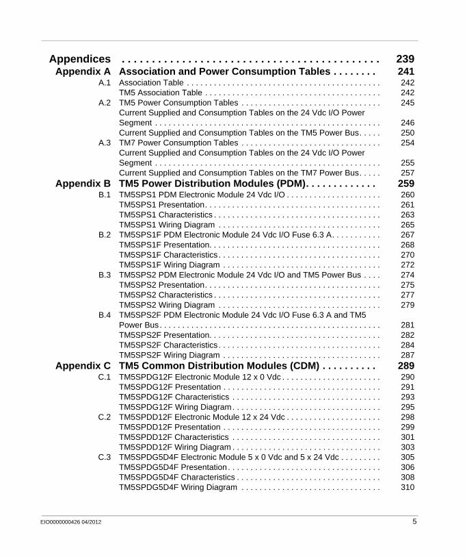
Appendices . . . . . . . . . . . . . . . . . . . . . . . . . . . . . . . . . . . . . . . . . . . 239Appendix A Association and Power Consumption Tables . . . . . . . . 241
A.1 Association Table . . . . . . . . . . . . . . . . . . . . . . . . . . . . . . . . . . . . . . . . . . . 242TM5 Association Table . . . . . . . . . . . . . . . . . . . . . . . . . . . . . . . . . . . . . . . 242
A.2 TM5 Power Consumption Tables . . . . . . . . . . . . . . . . . . . . . . . . . . . . . . . 245Current Supplied and Consumption Tables on the 24 Vdc I/O Power Segment . . . . . . . . . . . . . . . . . . . . . . . . . . . . . . . . . . . . . . . . . . . . . . . . . . 246Current Supplied and Consumption Tables on the TM5 Power Bus. . . . . 250
A.3 TM7 Power Consumption Tables . . . . . . . . . . . . . . . . . . . . . . . . . . . . . . . 254Current Supplied and Consumption Tables on the 24 Vdc I/O Power Segment . . . . . . . . . . . . . . . . . . . . . . . . . . . . . . . . . . . . . . . . . . . . . . . . . . 255Current Supplied and Consumption Tables on the TM7 Power Bus. . . . . 257
Appendix B TM5 Power Distribution Modules (PDM). . . . . . . . . . . . . 259B.1 TM5SPS1 PDM Electronic Module 24 Vdc I/O . . . . . . . . . . . . . . . . . . . . . 260
TM5SPS1 Presentation. . . . . . . . . . . . . . . . . . . . . . . . . . . . . . . . . . . . . . . 261TM5SPS1 Characteristics . . . . . . . . . . . . . . . . . . . . . . . . . . . . . . . . . . . . . 263TM5SPS1 Wiring Diagram . . . . . . . . . . . . . . . . . . . . . . . . . . . . . . . . . . . . 265
B.2 TM5SPS1F PDM Electronic Module 24 Vdc I/O Fuse 6.3 A. . . . . . . . . . . 267TM5SPS1F Presentation. . . . . . . . . . . . . . . . . . . . . . . . . . . . . . . . . . . . . . 268TM5SPS1F Characteristics . . . . . . . . . . . . . . . . . . . . . . . . . . . . . . . . . . . . 270TM5SPS1F Wiring Diagram . . . . . . . . . . . . . . . . . . . . . . . . . . . . . . . . . . . 272
B.3 TM5SPS2 PDM Electronic Module 24 Vdc I/O and TM5 Power Bus . . . . 274TM5SPS2 Presentation. . . . . . . . . . . . . . . . . . . . . . . . . . . . . . . . . . . . . . . 275TM5SPS2 Characteristics . . . . . . . . . . . . . . . . . . . . . . . . . . . . . . . . . . . . . 277TM5SPS2 Wiring Diagram . . . . . . . . . . . . . . . . . . . . . . . . . . . . . . . . . . . . 279
B.4 TM5SPS2F PDM Electronic Module 24 Vdc I/O Fuse 6.3 A and TM5 Power Bus. . . . . . . . . . . . . . . . . . . . . . . . . . . . . . . . . . . . . . . . . . . . . . . . . 281TM5SPS2F Presentation. . . . . . . . . . . . . . . . . . . . . . . . . . . . . . . . . . . . . . 282TM5SPS2F Characteristics . . . . . . . . . . . . . . . . . . . . . . . . . . . . . . . . . . . . 284TM5SPS2F Wiring Diagram . . . . . . . . . . . . . . . . . . . . . . . . . . . . . . . . . . . 287
Appendix C TM5 Common Distribution Modules (CDM) . . . . . . . . . . 289C.1 TM5SPDG12F Electronic Module 12 x 0 Vdc . . . . . . . . . . . . . . . . . . . . . . 290
TM5SPDG12F Presentation . . . . . . . . . . . . . . . . . . . . . . . . . . . . . . . . . . . 291TM5SPDG12F Characteristics . . . . . . . . . . . . . . . . . . . . . . . . . . . . . . . . . 293TM5SPDG12F Wiring Diagram. . . . . . . . . . . . . . . . . . . . . . . . . . . . . . . . . 295
C.2 TM5SPDD12F Electronic Module 12 x 24 Vdc . . . . . . . . . . . . . . . . . . . . . 298TM5SPDD12F Presentation . . . . . . . . . . . . . . . . . . . . . . . . . . . . . . . . . . . 299TM5SPDD12F Characteristics . . . . . . . . . . . . . . . . . . . . . . . . . . . . . . . . . 301TM5SPDD12F Wiring Diagram . . . . . . . . . . . . . . . . . . . . . . . . . . . . . . . . . 303
C.3 TM5SPDG5D4F Electronic Module 5 x 0 Vdc and 5 x 24 Vdc . . . . . . . . . 305TM5SPDG5D4F Presentation . . . . . . . . . . . . . . . . . . . . . . . . . . . . . . . . . . 306TM5SPDG5D4F Characteristics . . . . . . . . . . . . . . . . . . . . . . . . . . . . . . . . 308TM5SPDG5D4F Wiring Diagram . . . . . . . . . . . . . . . . . . . . . . . . . . . . . . . 310
EIO0000000426 04/2012 5
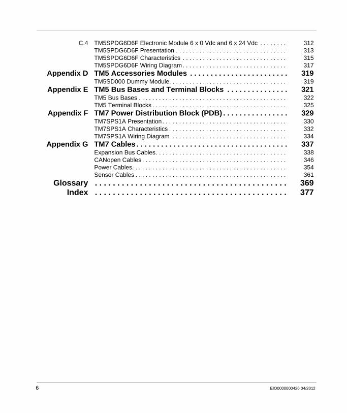
C.4 TM5SPDG6D6F Electronic Module 6 x 0 Vdc and 6 x 24 Vdc . . . . . . . . 312TM5SPDG6D6F Presentation . . . . . . . . . . . . . . . . . . . . . . . . . . . . . . . . . 313TM5SPDG6D6F Characteristics . . . . . . . . . . . . . . . . . . . . . . . . . . . . . . . 315TM5SPDG6D6F Wiring Diagram. . . . . . . . . . . . . . . . . . . . . . . . . . . . . . . 317
Appendix D TM5 Accessories Modules . . . . . . . . . . . . . . . . . . . . . . . . 319TM5SD000 Dummy Module. . . . . . . . . . . . . . . . . . . . . . . . . . . . . . . . . . . 319
Appendix E TM5 Bus Bases and Terminal Blocks . . . . . . . . . . . . . . . 321TM5 Bus Bases . . . . . . . . . . . . . . . . . . . . . . . . . . . . . . . . . . . . . . . . . . . . 322TM5 Terminal Blocks . . . . . . . . . . . . . . . . . . . . . . . . . . . . . . . . . . . . . . . . 325
Appendix F TM7 Power Distribution Block (PDB) . . . . . . . . . . . . . . . . 329TM7SPS1A Presentation. . . . . . . . . . . . . . . . . . . . . . . . . . . . . . . . . . . . . 330TM7SPS1A Characteristics . . . . . . . . . . . . . . . . . . . . . . . . . . . . . . . . . . . 332TM7SPS1A Wiring Diagram . . . . . . . . . . . . . . . . . . . . . . . . . . . . . . . . . . 334
Appendix G TM7 Cables . . . . . . . . . . . . . . . . . . . . . . . . . . . . . . . . . . . . . 337Expansion Bus Cables. . . . . . . . . . . . . . . . . . . . . . . . . . . . . . . . . . . . . . . 338CANopen Cables . . . . . . . . . . . . . . . . . . . . . . . . . . . . . . . . . . . . . . . . . . . 346Power Cables. . . . . . . . . . . . . . . . . . . . . . . . . . . . . . . . . . . . . . . . . . . . . . 354Sensor Cables . . . . . . . . . . . . . . . . . . . . . . . . . . . . . . . . . . . . . . . . . . . . . 361
Glossary . . . . . . . . . . . . . . . . . . . . . . . . . . . . . . . . . . . . . . . . . . . 369Index . . . . . . . . . . . . . . . . . . . . . . . . . . . . . . . . . . . . . . . . . . . 377
6 EIO0000000426 04/2012
§
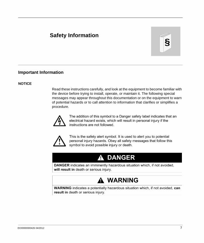
Safety InformationImportant Information
NOTICE
Read these instructions carefully, and look at the equipment to become familiar with the device before trying to install, operate, or maintain it. The following special messages may appear throughout this documentation or on the equipment to warn of potential hazards or to call attention to information that clarifies or simplifies a procedure.
EIO0000000426 04/2012 7

PLEASE NOTE
Electrical equipment should be installed, operated, serviced, and maintained only by qualified personnel. No responsibility is assumed by Schneider Electric for any consequences arising out of the use of this material.
A qualified person is one who has skills and knowledge related to the construction and operation of electrical equipment and its installation, and has received safety training to recognize and avoid the hazards involved.
8 EIO0000000426 04/2012
About the Book
At a Glance
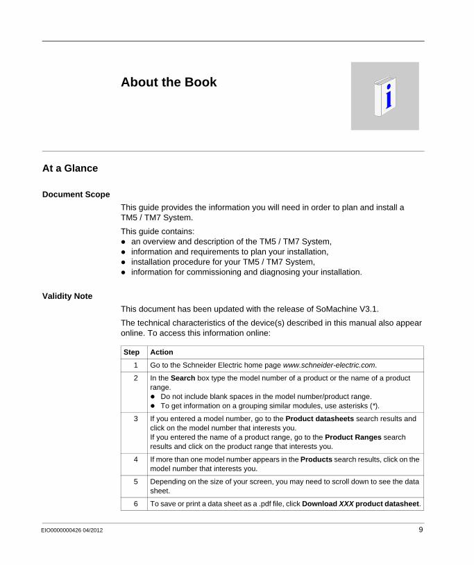
Document Scope
This guide provides the information you will need in order to plan and install a TM5 / TM7 System.
This guide contains:an overview and description of the TM5 / TM7 System,information and requirements to plan your installation,installation procedure for your TM5 / TM7 System,information for commissioning and diagnosing your installation.
Validity Note
This document has been updated with the release of SoMachine V3.1.
The technical characteristics of the device(s) described in this manual also appear online. To access this information online:
Step Action
1 Go to the Schneider Electric home page www.schneider-electric.com.
2 In the Search box type the model number of a product or the name of a product range.
Do not include blank spaces in the model number/product range.To get information on a grouping similar modules, use asterisks (*).
3 If you entered a model number, go to the Product datasheets search results and click on the model number that interests you.If you entered the name of a product range, go to the Product Ranges search results and click on the product range that interests you.
4 If more than one model number appears in the Products search results, click on the model number that interests you.
5 Depending on the size of your screen, you may need to scroll down to see the data sheet.
6 To save or print a data sheet as a .pdf file, click Download XXX product datasheet.
EIO0000000426 04/2012 9
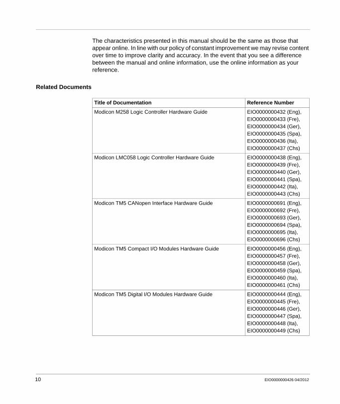
The characteristics presented in this manual should be the same as those that appear online. In line with our policy of constant improvement we may revise content over time to improve clarity and accuracy. In the event that you see a difference between the manual and online information, use the online information as your reference.
Related Documents
Title of Documentation Reference Number
Modicon M258 Logic Controller Hardware Guide EIO0000000432 (Eng), EIO0000000433 (Fre), EIO0000000434 (Ger), EIO0000000435 (Spa), EIO0000000436 (Ita), EIO0000000437 (Chs)
Modicon LMC058 Logic Controller Hardware Guide EIO0000000438 (Eng), EIO0000000439 (Fre), EIO0000000440 (Ger), EIO0000000441 (Spa), EIO0000000442 (Ita), EIO0000000443 (Chs)
Modicon TM5 CANopen Interface Hardware Guide EIO0000000691 (Eng), EIO0000000692 (Fre), EIO0000000693 (Ger), EIO0000000694 (Spa), EIO0000000695 (Ita), EIO0000000696 (Chs)
Modicon TM5 Compact I/O Modules Hardware Guide EIO0000000456 (Eng), EIO0000000457 (Fre), EIO0000000458 (Ger), EIO0000000459 (Spa), EIO0000000460 (Ita), EIO0000000461 (Chs)
Modicon TM5 Digital I/O Modules Hardware Guide EIO0000000444 (Eng), EIO0000000445 (Fre), EIO0000000446 (Ger), EIO0000000447 (Spa), EIO0000000448 (Ita), EIO0000000449 (Chs)
10 EIO0000000426 04/2012
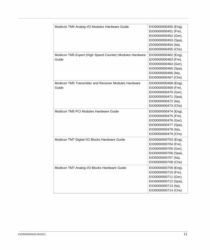
Modicon TM5 Analog I/O Modules Hardware Guide EIO0000000450 (Eng), EIO0000000451 (Fre), EIO0000000452 (Ger), EIO0000000453 (Spa), EIO0000000454 (Ita), EIO0000000455 (Chs)
Modicon TM5 Expert (High Speed Counter) Modules Hardware Guide
EIO0000000462 (Eng), EIO0000000463 (Fre), EIO0000000464 (Ger), EIO0000000465 (Spa), EIO0000000466 (Ita), EIO0000000467 (Chs)
Modicon TM5 Transmitter and Receiver Modules Hardware Guide
EIO0000000468 (Eng), EIO0000000469 (Fre), EIO0000000470 (Ger), EIO0000000471 (Spa), EIO0000000472 (Ita), EIO0000000473 (Chs)
Modicon TM5 PCI Modules Hardware Guide EIO0000000474 (Eng), EIO0000000475 (Fre), EIO0000000476 (Ger), EIO0000000477 (Spa), EIO0000000478 (Ita), EIO0000000479 (Chs)
Modicon TM7 Digital I/O Blocks Hardware Guide EIO0000000703 (Eng), EIO0000000704 (Fre), EIO0000000705 (Ger), EIO0000000706 (Spa), EIO0000000707 (Ita), EIO0000000708 (Chs)
Modicon TM7 Analog I/O Blocks Hardware Guide EIO0000000709 (Eng), EIO0000000710 (Fre), EIO0000000711 (Ger), EIO0000000712 (Spa), EIO0000000713 (Ita), EIO0000000714 (Chs)
EIO0000000426 04/2012 11
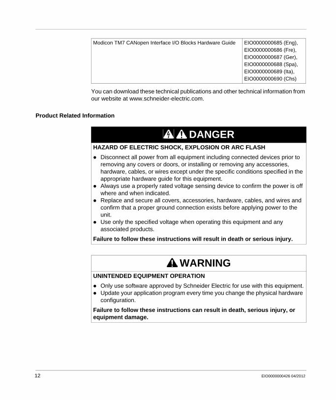
You can download these technical publications and other technical information from our website at www.schneider-electric.com.
Product Related Information
Modicon TM7 CANopen Interface I/O Blocks Hardware Guide EIO0000000685 (Eng), EIO0000000686 (Fre), EIO0000000687 (Ger), EIO0000000688 (Spa), EIO0000000689 (Ita), EIO0000000690 (Chs)
DANGERHAZARD OF ELECTRIC SHOCK, EXPLOSION OR ARC FLASH
Disconnect all power from all equipment including connected devices prior to removing any covers or doors, or installing or removing any accessories, hardware, cables, or wires except under the specific conditions specified in the appropriate hardware guide for this equipment.Always use a properly rated voltage sensing device to confirm the power is off where and when indicated.Replace and secure all covers, accessories, hardware, cables, and wires and confirm that a proper ground connection exists before applying power to the unit.Use only the specified voltage when operating this equipment and any associated products.
Failure to follow these instructions will result in death or serious injury.
WARNINGUNINTENDED EQUIPMENT OPERATION
Only use software approved by Schneider Electric for use with this equipment.Update your application program every time you change the physical hardware configuration.
Failure to follow these instructions can result in death, serious injury, or equipment damage.
12 EIO0000000426 04/2012
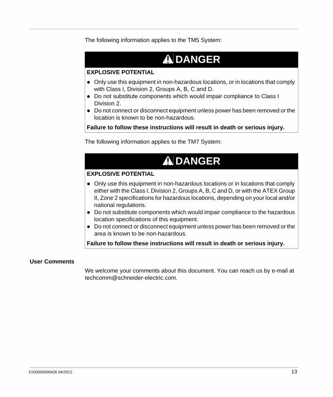
The following information applies to the TM5 System:
The following information applies to the TM7 System:
User Comments
We welcome your comments about this document. You can reach us by e-mail at [email protected].
DANGEREXPLOSIVE POTENTIAL
Only use this equipment in non-hazardous locations, or in locations that comply with Class I, Division 2, Groups A, B, C and D.Do not substitute components which would impair compliance to Class I Division 2.Do not connect or disconnect equipment unless power has been removed or the location is known to be non-hazardous.
Failure to follow these instructions will result in death or serious injury.
DANGEREXPLOSIVE POTENTIAL
Only use this equipment in non-hazardous locations or in locations that comply either with the Class I, Division 2, Groups A, B, C and D, or with the ATEX Group II, Zone 2 specifications for hazardous locations, depending on your local and/or national regulations.Do not substitute components which would impair compliance to the hazardous location specifications of this equipment.Do not connect or disconnect equipment unless power has been removed or the area is known to be non-hazardous.
Failure to follow these instructions will result in death or serious injury.
EIO0000000426 04/2012 13

14 EIO0000000426 04/2012
EIO0000000426 04/2012
I
Modicon TM5 / TM7 Flexible System
Introduction to the TM5 / TM7 System
EIO0000000426 04/2012
Introduction to the TM5 / TM7 System
Overview
This manual provides an overview of the TM5 and TM7 system:The TM5 System is comprised of IP20-rated components with which you can create local, remote and / or distributed I/O architectures. A typical TM5 System includes a controller and may include field bus interface, slices, compact I/O and accessories. These components must be installed in enclosures appropriate to the intended operating environment.The TM7 System is comprised of IP67-rated components with which you can create remote and / or distributed I/O architectures. TM7 System including field bus interface I/O blocks, expansion blocks and accessories can be used in environments conforming to IP67 (splashing water, oil, dust, etc...).
What’s in this Part?
This part contains the following chapters:
Chapter Chapter Name Page
1 Basics of the TM5 / TM7 System 17
2 Description of the TM5 System 27
3 Description of the TM7 System 53
15

Introduction to the TM5 / TM7 System
16 EIO0000000426 04/2012
EIO0000000426 04/2012
1
Modicon TM5 / TM7 Flexible System
Basics of the TM5 / TM7 System
EIO0000000426 04/2012
Basics of the TM5 / TM7 System
Overview
This chapter provides an overview of the TM5 / TM7 System architecture (local, remote and distributed). Also the color coding principle of the TM5 System is described.
What’s in this Chapter?
This chapter contains the following topics:
Topic Page
TM5 / TM7 Controller System Architecture 18
TM5 / TM7 Distributed I/Os Architecture 21
Color Coding of the TM5 System 24
17

Basics of the TM5 / TM7 System
TM5 / TM7 Controller System Architecture
Introduction
The TM5 / TM7 System is a flexible control system:
The flexibility is obtained by the association of:TM5 System
ControllerField bus interface moduleCompact I/OSlicesAccessories
TM7 SystemTM7 Field bus interface I/O blocksBlocksAccessories
The controller with embedded I/Os and networking is the main component of the TM5 / TM7 System. It can be expanded by compact I/O, slices and/or blocks.
An expansion module is a compact I/O or a slice in this documentation.
The compact I/O is used to expand and adjust the number of I/O in the TM5 System to the exact needs of your application.
18 EIO0000000426 04/2012
Basics of the TM5 / TM7 System
A slice has one of the following functions in the TM5 System:Expansion I/Os orPower distribution orCommon distribution orExpansion bus
A block has one of the following functions in the TM7 System:Expansion I/Os orPower distribution
The expansion modules and blocks are used:to expand and adjust the number of I/O in a TM5 / TM7 System to the exact needs of your application.to manage the distribution of power for electronic modules and I/O (for example separation of 24 Vdc inputs from 24 Vdc outputs...)
Application requirements determine the architecture of your TM5 / TM7 System.
Depending on your needs, the local configuration architecture may optionally be expanded to include remote expansion I/Os and/or distributed I/O systems.
Remote I/O expansions are made by extending the internal TM5 data bus through the use of TM5 Transmitters and Receivers.
Distributed I/O expansions are made through the use of industrial networks (such as CANopen, Ethernet,...). These networks can be created using the integrated communication ports on the controller or the optional TM5 PCI modules.
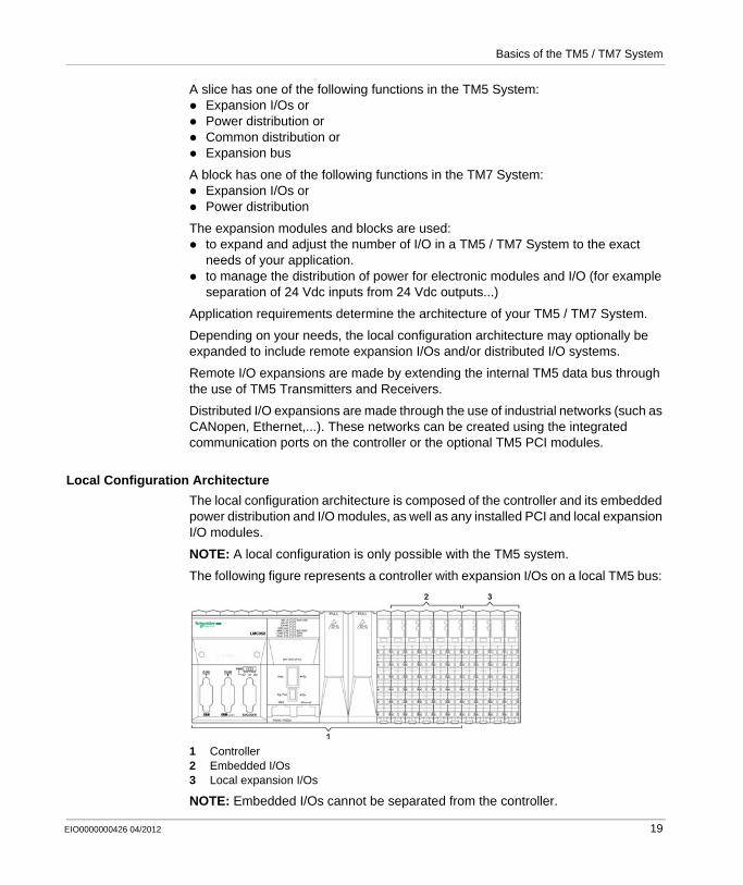
Local Configuration Architecture
The local configuration architecture is composed of the controller and its embedded power distribution and I/O modules, as well as any installed PCI and local expansion I/O modules.
NOTE: A local configuration is only possible with the TM5 system.
The following figure represents a controller with expansion I/Os on a local TM5 bus:
1 Controller2 Embedded I/Os3 Local expansion I/Os
NOTE: Embedded I/Os cannot be separated from the controller.
EIO0000000426 04/2012 19
Basics of the TM5 / TM7 System
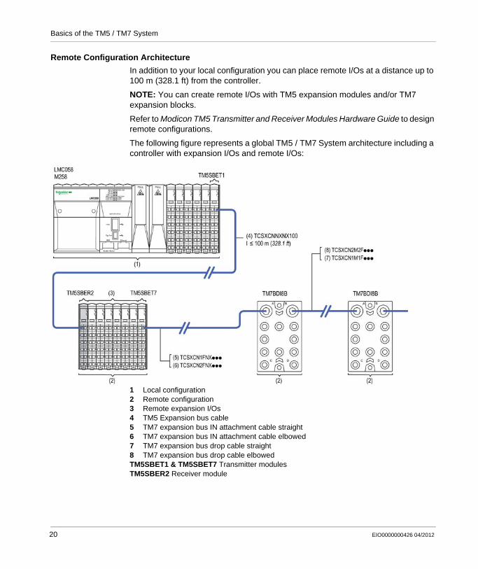
Remote Configuration Architecture
In addition to your local configuration you can place remote I/Os at a distance up to 100 m (328.1 ft) from the controller.
NOTE: You can create remote I/Os with TM5 expansion modules and/or TM7 expansion blocks.
Refer to Modicon TM5 Transmitter and Receiver Modules Hardware Guide to design remote configurations.
The following figure represents a global TM5 / TM7 System architecture including a controller with expansion I/Os and remote I/Os:
1 Local configuration2 Remote configuration3 Remote expansion I/Os4 TM5 Expansion bus cable5 TM7 expansion bus IN attachment cable straight6 TM7 expansion bus IN attachment cable elbowed7 TM7 expansion bus drop cable straight8 TM7 expansion bus drop cable elbowedTM5SBET1 & TM5SBET7 Transmitter modulesTM5SBER2 Receiver module
20 EIO0000000426 04/2012
Basics of the TM5 / TM7 System
TM5 / TM7 Distributed I/Os Architecture
Introduction
The TM5 / TM7 System is an open system and can operate with the following open field bus standards:
CANopen for TM5 / TM7 SystemSERCOS for TM5 System
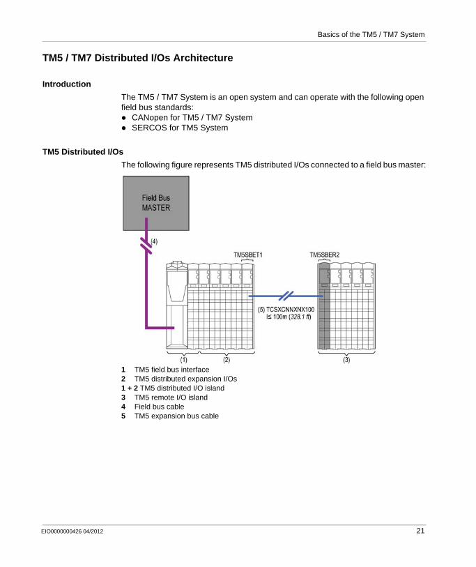
TM5 Distributed I/Os
The following figure represents TM5 distributed I/Os connected to a field bus master:
1 TM5 field bus interface2 TM5 distributed expansion I/Os1 + 2 TM5 distributed I/O island3 TM5 remote I/O island4 Field bus cable5 TM5 expansion bus cable
EIO0000000426 04/2012 21
Basics of the TM5 / TM7 System
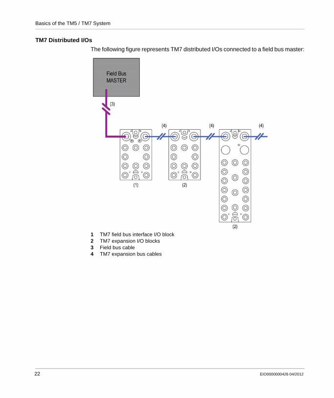
TM7 Distributed I/Os
The following figure represents TM7 distributed I/Os connected to a field bus master:
1 TM7 field bus interface I/O block2 TM7 expansion I/O blocks3 Field bus cable4 TM7 expansion bus cables
22 EIO0000000426 04/2012
Basics of the TM5 / TM7 System
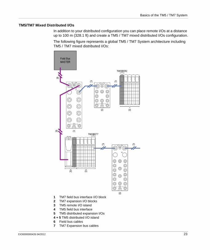
TM5/TM7 Mixed Distributed I/Os
In addition to your distributed configuration you can place remote I/Os at a distance up to 100 m (328.1 ft) and create a TM5 / TM7 mixed distributed I/Os configuration.
The following figure represents a global TM5 / TM7 System architecture including TM5 / TM7 mixed distributed I/Os:
1 TM7 field bus interface I/O block2 TM7 expansion I/O blocks3 TM5 remote I/O island4 TM5 field bus interface5 TM5 distributed expansion I/Os4 + 5 TM5 distributed I/O island6 Field bus cables7 TM7 Expansion bus cables
EIO0000000426 04/2012 23

Basics of the TM5 / TM7 System
Color Coding of the TM5 System
Overview
The following figure shows colors of the TM5 components:
1 Controller2 Field bus interface3 Slices4 Compact I/O
Controller Color Assignment
The color of all the controllers and their removable terminal blocks is white.
24 EIO0000000426 04/2012

Basics of the TM5 / TM7 System
Field Bus Interface Color Assignment
Two colors are used for the four components of a field bus interface (see page 34):White for the:
field bus interface bus base and,field bus interface module.
Gray for the:Interface Power Distribution Module (IPDM) and,associated terminal block.
Slice Color Assignment
For all modules other than the Compact I/O, an assembled TM5 module (referred to as a slice) is composed of a bus base, an electronic module, and a terminal block. Each slice (see page 43) of the TM5 System is color coded for improved identification.
Three colors are used:WhiteGrayBlack
The color of a slice is defined by a combination of:Input or output voltage,Functionality.
The following table gives the colors of the different types of slices:
Voltage Functionality White Gray Black
24 Vdc I/Os X – –
Power distribution – X –
TM5 bus transmission X – –
TM5 bus reception – X –
100...240 Vac I/Os – – X
24 Vdc / 230 Vac Relay – – X
EIO0000000426 04/2012 25
Basics of the TM5 / TM7 System
NOTE: Check the compatibility of components with the association table (see page 242) before installation.
Compact I/O Color Assignment
The color of all the compact I/O and their removable terminal blocks is white.
DANGERINCOMPATIBLE COMPONENTS CAUSE ELECTRONIC SHOCK OR ARC FLASH
Do not associate components of a slice that have different colors.Always confirm the compatibility of slice components and modules before installation using the association table in this manual.Ensure that a correct terminal block is installed on the appropriate electronic module.
Failure to follow these instructions will result in death or serious injury.
26 EIO0000000426 04/2012
EIO0000000426 04/2012
2
Modicon TM5 / TM7 Flexible System
Description of the TM5 System
EIO0000000426 04/2012
Description of the TM5 System
Overview
This chapter provides a brief description of the constituent parts of the TM5 System. It describes the controller, the field bus interface, the slice, the compact I/O module and the accessories.
What’s in this Chapter?
This chapter contains the following topics:
Topic Page
Controller Description 28
Field Bus Interface Description 34
Compact I/O Description 39
Slice Description 43
Accessories 47
27
Description of the TM5 System
Controller Description
Introduction
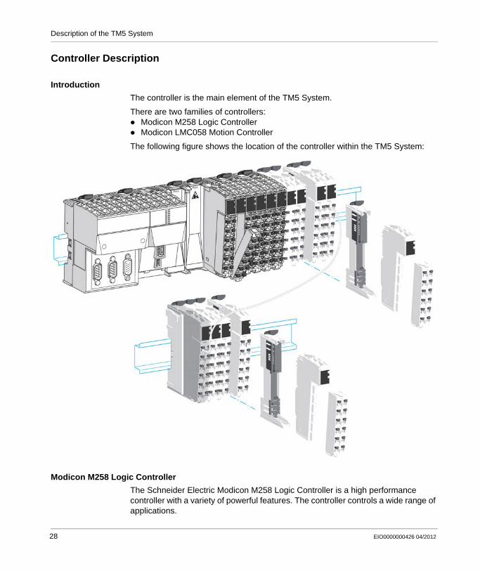
The controller is the main element of the TM5 System.
There are two families of controllers:Modicon M258 Logic ControllerModicon LMC058 Motion Controller
The following figure shows the location of the controller within the TM5 System:
Modicon M258 Logic Controller
The Schneider Electric Modicon M258 Logic Controller is a high performance controller with a variety of powerful features. The controller controls a wide range of applications.
28 EIO0000000426 04/2012

Description of the TM5 System
Mechanical, hardware, and firmware features are described in the Modicon M258 Hardware Guide.
The following tables describes the controller references available for your TM5 System:
Modicon LMC058 Motion Controller
The Schneider Electric Modicon LMC058 Motion Controller (LMC058) is a high performance motion controller with a variety of powerful features. The LMC058 controls a wide range of applications.
Mechanical, hardware, and firmware features are described in the Modicon LMC058 Hardware Guide.
The following tables describes the controller references available for your TM5 System:
PCI CAN USB A USB Pgr Eth SL
TM258LD42DT 0 0 1 1 1 1
TM258LD42DT4L 2 0 1 1 1 1
TM258LF42DT•• 0 1 1 1 1 1
TM258LF42DT4L•• 2 1 1 1 1 1
TM258LF66DT4L•• 2 1 1 1 1 1
TM258LF42DR•• 2 1 1 1 1 1
Embedded expert I/O Embedded regular I/O
Fast Inputs
Fast Outputs
Regular Inputs
Digital Inputs
Digital Outputs
Analog Inputs
TM258LD42DT 2x 5 2 2 1x 12 12 0x 0
TM258LD42DT4L 2x 5 2 2 1x 12 12 1x 4
TM258LF42DT•• 2x 5 2 2 1x 12 12 0x 0
TM258LF42DT4L•• 2x 5 2 2 1x 12 12 1x 4
TM258LF66DT4L•• 2x 5 2 2 2x 12 12 1x 4
TM258LF42DR•• 2x 5 2 2 2x 6 6 Relays 0x 0
PCI CAN USB A USB Pgr Eth SL ENC
LMC058LF42•• 0 2 1 1 1 1 1
LMC058LF424•• 2 2 1 1 1 1 1
EIO0000000426 04/2012 29
Description of the TM5 System
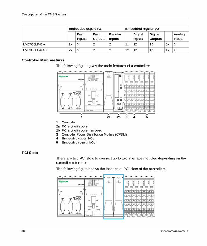
Controller Main Features
The following figure gives the main features of a controller:
1 Controller2a PCI slot with cover2b PCI slot with cover removed3 Controller Power Distribution Module (CPDM)4 Embedded expert I/Os5 Embedded regular I/Os
PCI Slots
There are two PCI slots to connect up to two interface modules depending on the controller reference.
The following figure shows the location of PCI slots of the controllers:
Embedded expert I/O Embedded regular I/O
Fast Inputs
Fast Outputs
Regular Inputs
Digital Inputs
Digital Outputs
Analog Inputs
LMC058LF42•• 2x 5 2 2 1x 12 12 0x 0
LMC058LF424•• 2x 5 2 2 1x 12 12 1x 4
30 EIO0000000426 04/2012

Description of the TM5 System
The PCI modules are used for specific application expansions of the controller. They are inserted in the PCI slots of the controller:
For more details refer to the Modicon TM5 PCI Modules Hardware Guide.
Controller Power Distribution Module (CPDM)
The distribution of power by the CDPM consists of three dedicated electrical circuits:
Reference Type Description
TM5PCRS2 Serial line TM5 interface electronic module, 1 RS-232, electrically isolated
TM5PCRS4 Serial line TM5 interface electronic module, 1 RS-485, electrically isolated
TM5PCDPS Profibus DP TM5 interface electronic module, 1 RS-485, electrically isolated
NOTICEELECTROSTATIC DISCHARGE
Ensure that empty PCI slots have their covers in place before applying power to the controller.Never touch an exposed PCI connector.
Failure to follow these instructions can result in equipment damage.
Designation Description
24 Vdc embedded expert modules power
24 Vdc power that serves the embedded expert I/O modules of the controller and the encoder (depends on references)
24 Vdc Main power 24 Vdc power that serves the electronics of the controller and generates independent power for:
PCI communication modules (depends on references),Modbus connected devices,USB keys,Electronics of the embedded regular I/O,TM5 power bus that serves the expansion modules.
24 Vdc I/O power segment
The 24 Vdc power that serves:the embedded regular I/O,the sensors and actuators connected to the embedded regular I/O,the expansion modules,the sensors and actuators connected to the expansion modules,the external devices connected to the Common Distribution Modules (CDM).
EIO0000000426 04/2012 31

Description of the TM5 System
The following figure shows the terminal block assignments of the CPDM:
1 24 Vdc embedded expert modules power2 24 Vdc Main power3 24 Vdc I/O power segment
Embedded Expert I/Os
The following figure shows the location of the expert I/Os of the controller:
The controllers have two embedded expert I/O groups. Each group contains:5 fast inputs2 regular inputs2 fast outputs
32 EIO0000000426 04/2012

Description of the TM5 System
Each group can be configured as:1 to 4 simple High Speed Counters (HSC)1 main HSC1 Pulse Width Modulated (PWM) output1 frequency generator1 encoder interface
Fast inputs resolution is up to 200 kHz.
NOTE: When a fast input is not used by special function, it can be used as a regular input.
Fast outputs resolution is up to 100 kHz.
NOTE: When a fast output is not used by special function, it can be used as a regular output.
Embedded Regular I/Os
The following figure shows the location of the embedded regular I/Os of the controller:
The following table gives a short description of the different regular I/Os embedded in the controller, depending on the controller reference:
Regular I/Os Short Description
Digital Inputs 24 Vdc sink / 1 or 2 wires / input Type 1
Digital Outputs 24 Vdc source / 1 wire / transistor / 0.5 A
Analog Inputs 12 bit resolution / -10...+10 Vdc / 0...20 mA / 4...20 mA
Relay Outputs 2 A / 30 Vdc / 240 Vac
EIO0000000426 04/2012 33

Description of the TM5 System
Field Bus Interface Description
Introduction
The TM5 field bus interface is the first element of the TM5 distributed I/O island (see page 21). The following figure shows the location of the TM5 field bus interface in a distributed I/O island:
34 EIO0000000426 04/2012
Description of the TM5 System
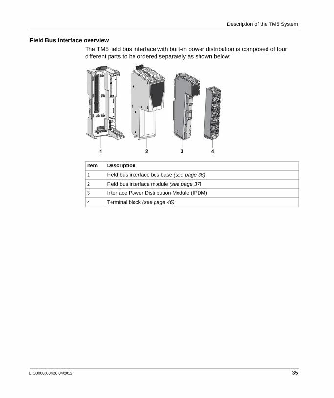
Field Bus Interface overview
The TM5 field bus interface with built-in power distribution is composed of four different parts to be ordered separately as shown below:
Item Description
1 Field bus interface bus base (see page 36)
2 Field bus interface module (see page 37)
3 Interface Power Distribution Module (IPDM)
4 Terminal block (see page 46)
EIO0000000426 04/2012 35
Description of the TM5 System
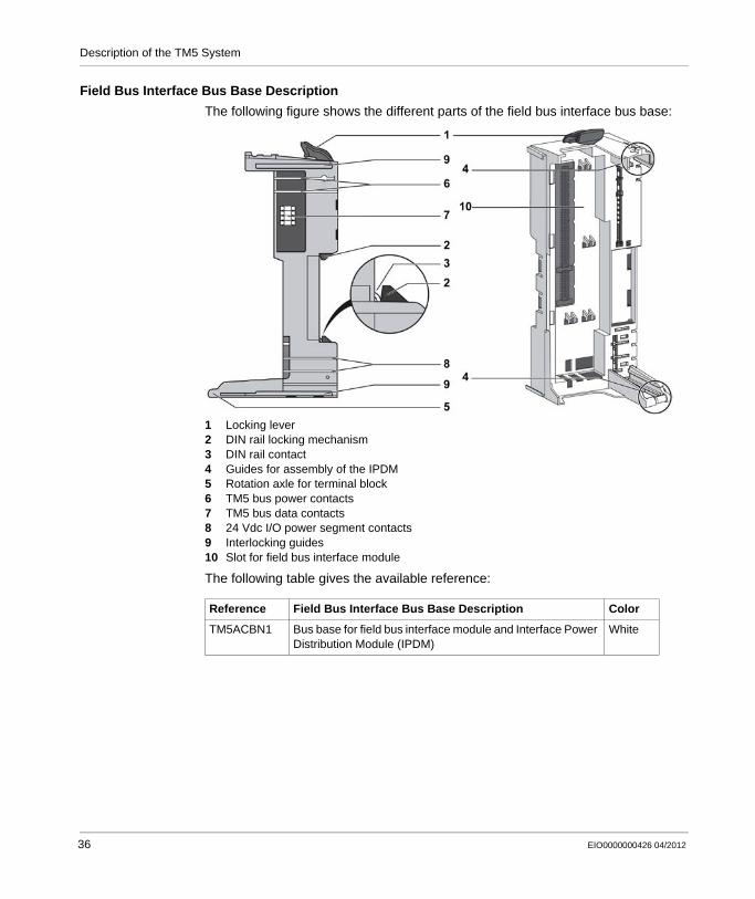
Field Bus Interface Bus Base Description
The following figure shows the different parts of the field bus interface bus base:
1 Locking lever2 DIN rail locking mechanism3 DIN rail contact4 Guides for assembly of the IPDM5 Rotation axle for terminal block6 TM5 bus power contacts7 TM5 bus data contacts8 24 Vdc I/O power segment contacts9 Interlocking guides10 Slot for field bus interface module
The following table gives the available reference:
Reference Field Bus Interface Bus Base Description Color
TM5ACBN1 Bus base for field bus interface module and Interface Power Distribution Module (IPDM)
White
36 EIO0000000426 04/2012

Description of the TM5 System
Field Bus Interface Module Description
The following figure shows the front view of the field bus interface module:
1 Locking clip2 Front view3 Field bus connector
The following table gives the available reference:
Interface Power Distribution Module (IPDM)
The following table gives the available reference:
The distribution of the power by the IPDM consists of two dedicated electrical circuits:
Reference Field Bus Interface Module Description Color
TM5NCO1 CANopen interface module White
TM5NS31 SERCOS® Ι Ι Ι interface module White
Reference IPDM Description (see page 45) Color
TM5SPS3 Field bus interface 24 Vdc power supply Gray
Designation: Description:
24 Vdc Main power 24 Vdc power that serves the electronics of the field bus Interface Module and generates independent power for the TM5 power bus that serves the expansion modules.
24 Vdc I/O power segment
The 24 Vdc power that serves:the expansion modules,the sensors and actuators connected to the expansion modules,the external devices connected to the Common Distribution Modules (CDM).
EIO0000000426 04/2012 37
Description of the TM5 System
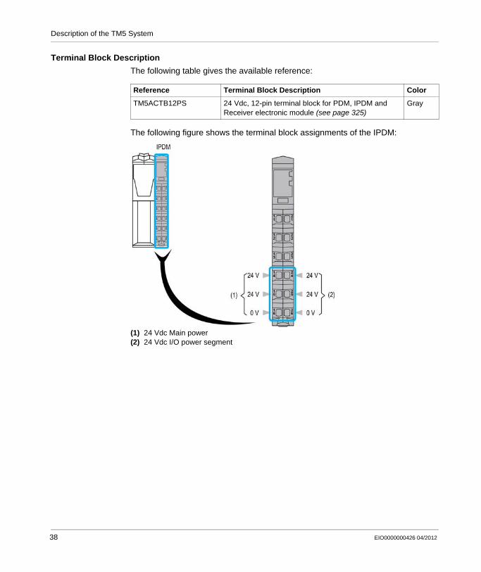
Terminal Block Description
The following table gives the available reference:
The following figure shows the terminal block assignments of the IPDM:
(1) 24 Vdc Main power(2) 24 Vdc I/O power segment
Reference Terminal Block Description Color
TM5ACTB12PS 24 Vdc, 12-pin terminal block for PDM, IPDM and Receiver electronic module (see page 325)
Gray
38 EIO0000000426 04/2012
Description of the TM5 System
Compact I/O Description
Introduction
The TM5 Compact I/O are I/O expansion modules for your TM5 system. The compact I/O are a group of regular TM5 electronic I/O modules under a single reference. The individual electronic modules are identified by an abbreviated designation on their front face, while the reference of the entire group can be found on the side of the compact I/O module. The abbreviated designation on the individual module faces corresponds to the last characters of the individual module references.The terminals blocks are assembled on the compact I/O when delivered.
The compact I/O uses a single address on the TM5 Bus.
The electronic modules included in the compact I/O are not individually replaceable.
NOTE: Unlike the TM5 digital and analog I/O electronic modules, the compact I/O do not have hot-swap capability. Do not attempt to hot swap these modules.
WARNINGUNINTENDED EQUIPMENT OPERATION
Do not attempt to hot swap TM5 Compact I/O.
Failure to follow these instructions can result in death, serious injury, or equipment damage.
EIO0000000426 04/2012 39

Description of the TM5 System
The following figure shows a TM5 Compact I/O as the second component of a remote island:
Compact I/O
The range of compact I/O includes:digital input electronic modulesdigital output electronic modulesanalog input electronic modulesanalog output electronic modules
Every electronic module channel has a status LED.
Mechanical and hardware features are described in the Modicon TM5 Compact I/O Modules Hardware Guide.
The following table describes the compact I/O reference available for your TM5 System:
Reference Number and Channel Type
Digital Inputs
Digital Outputs Analog Inputs Analog Outputs
TM5C24D18T 2x12In 24 3x6Out 18 – 0 – 0
TM5C12D8T 3x4In 12 2x4Out 8 – 0 – 0
TM5C24D12R 2x12In 24 2x6Rel 12 Relays – 0 – 0
TM5CAI8O8VL – 0 – 0 2x4AI ±10 V 8 2x4AO ±10 V 8
TM5CAI8O8CL – 0 – 0 2x4AI 0-20 mA / 4-20 mA 8 2x4AO 0-20 mA 8
40 EIO0000000426 04/2012
Description of the TM5 System
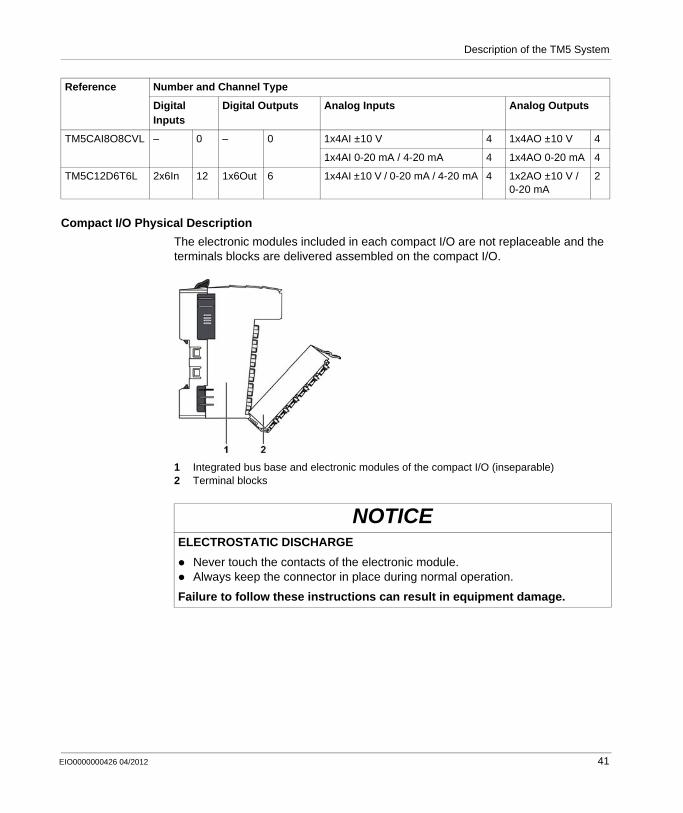
Compact I/O Physical Description
The electronic modules included in each compact I/O are not replaceable and the terminals blocks are delivered assembled on the compact I/O.
1 Integrated bus base and electronic modules of the compact I/O (inseparable)2 Terminal blocks
TM5CAI8O8CVL – 0 – 0 1x4AI ±10 V 4 1x4AO ±10 V 4
1x4AI 0-20 mA / 4-20 mA 4 1x4AO 0-20 mA 4
TM5C12D6T6L 2x6In 12 1x6Out 6 1x4AI ±10 V / 0-20 mA / 4-20 mA 4 1x2AO ±10 V / 0-20 mA
2
Reference Number and Channel Type
Digital Inputs
Digital Outputs Analog Inputs Analog Outputs
NOTICEELECTROSTATIC DISCHARGE
Never touch the contacts of the electronic module.Always keep the connector in place during normal operation.
Failure to follow these instructions can result in equipment damage.
EIO0000000426 04/2012 41
Description of the TM5 System
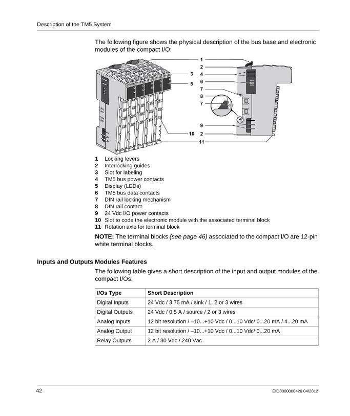
The following figure shows the physical description of the bus base and electronic modules of the compact I/O:
1 Locking levers2 Interlocking guides3 Slot for labeling4 TM5 bus power contacts5 Display (LEDs)6 TM5 bus data contacts7 DIN rail locking mechanism8 DIN rail contact9 24 Vdc I/O power contacts10 Slot to code the electronic module with the associated terminal block11 Rotation axle for terminal block
NOTE: The terminal blocks (see page 46) associated to the compact I/O are 12-pin white terminal blocks.
Inputs and Outputs Modules Features
The following table gives a short description of the input and output modules of the compact I/Os:
I/Os Type Short Description
Digital Inputs 24 Vdc / 3.75 mA / sink / 1, 2 or 3 wires
Digital Outputs 24 Vdc / 0.5 A / source / 2 or 3 wires
Analog Inputs 12 bit resolution / –10...+10 Vdc / 0...10 Vdc/ 0...20 mA / 4...20 mA
Analog Output 12 bit resolution / –10...+10 Vdc / 0...10 Vdc/ 0...20 mA
Relay Outputs 2 A / 30 Vdc / 240 Vac
42 EIO0000000426 04/2012
Description of the TM5 System
Slice Description
Overview
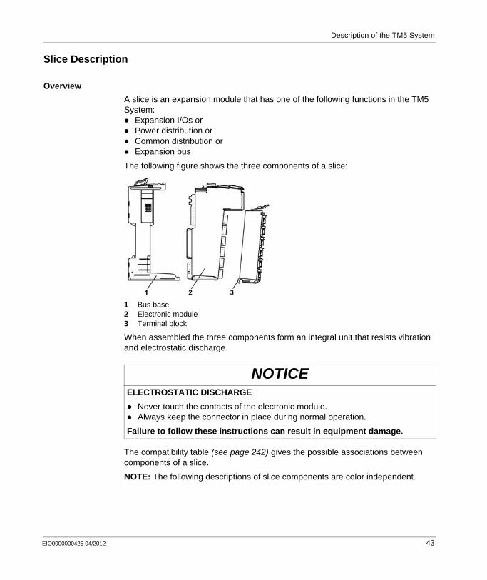
A slice is an expansion module that has one of the following functions in the TM5 System:
Expansion I/Os orPower distribution orCommon distribution orExpansion bus
The following figure shows the three components of a slice:
1 Bus base2 Electronic module3 Terminal block
When assembled the three components form an integral unit that resists vibration and electrostatic discharge.
The compatibility table (see page 242) gives the possible associations between components of a slice.
NOTE: The following descriptions of slice components are color independent.
NOTICEELECTROSTATIC DISCHARGE
Never touch the contacts of the electronic module.Always keep the connector in place during normal operation.
Failure to follow these instructions can result in equipment damage.
EIO0000000426 04/2012 43
Description of the TM5 System
Bus Base Description
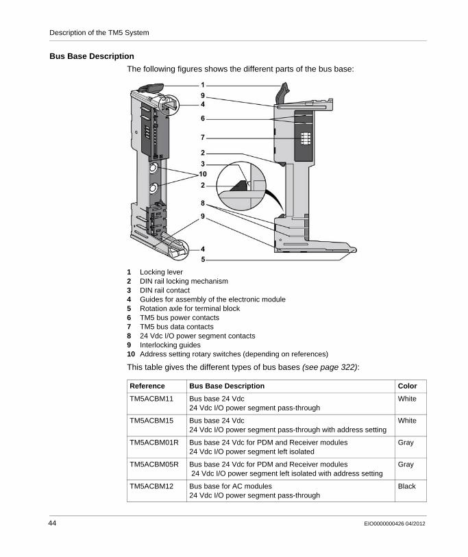
The following figures shows the different parts of the bus base:
1 Locking lever2 DIN rail locking mechanism3 DIN rail contact4 Guides for assembly of the electronic module5 Rotation axle for terminal block6 TM5 bus power contacts7 TM5 bus data contacts8 24 Vdc I/O power segment contacts9 Interlocking guides10 Address setting rotary switches (depending on references)
This table gives the different types of bus bases (see page 322):
Reference Bus Base Description Color
TM5ACBM11 Bus base 24 Vdc24 Vdc I/O power segment pass-through
White
TM5ACBM15 Bus base 24 Vdc24 Vdc I/O power segment pass-through with address setting
White
TM5ACBM01R Bus base 24 Vdc for PDM and Receiver modules24 Vdc I/O power segment left isolated
Gray
TM5ACBM05R Bus base 24 Vdc for PDM and Receiver modules 24 Vdc I/O power segment left isolated with address setting
Gray
TM5ACBM12 Bus base for AC modules24 Vdc I/O power segment pass-through
Black
44 EIO0000000426 04/2012
Description of the TM5 System
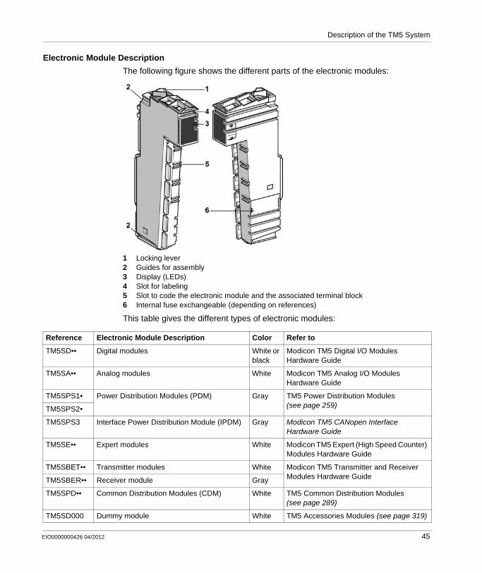
Electronic Module Description
The following figure shows the different parts of the electronic modules:
1 Locking lever2 Guides for assembly3 Display (LEDs)4 Slot for labeling5 Slot to code the electronic module and the associated terminal block6 Internal fuse exchangeable (depending on references)
This table gives the different types of electronic modules:
Reference Electronic Module Description Color Refer to
TM5SD•• Digital modules White or black
Modicon TM5 Digital I/O Modules Hardware Guide
TM5SA•• Analog modules White Modicon TM5 Analog I/O Modules Hardware Guide
TM5SPS1• Power Distribution Modules (PDM) Gray TM5 Power Distribution Modules (see page 259)TM5SPS2•
TM5SPS3 Interface Power Distribution Module (IPDM) Gray Modicon TM5 CANopen Interface Hardware Guide
TM5SE•• Expert modules White Modicon TM5 Expert (High Speed Counter) Modules Hardware Guide
TM5SBET•• Transmitter modules White Modicon TM5 Transmitter and Receiver Modules Hardware GuideTM5SBER•• Receiver module Gray
TM5SPD•• Common Distribution Modules (CDM) White TM5 Common Distribution Modules (see page 289)
TM5SD000 Dummy module White TM5 Accessories Modules (see page 319)
EIO0000000426 04/2012 45
Description of the TM5 System
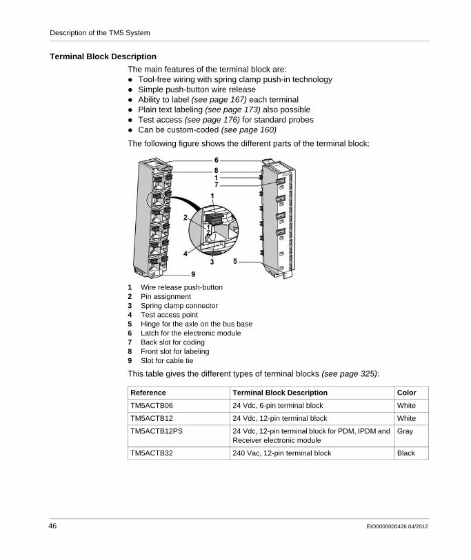
Terminal Block Description
The main features of the terminal block are:Tool-free wiring with spring clamp push-in technologySimple push-button wire releaseAbility to label (see page 167) each terminalPlain text labeling (see page 173) also possibleTest access (see page 176) for standard probesCan be custom-coded (see page 160)
The following figure shows the different parts of the terminal block:
1 Wire release push-button2 Pin assignment3 Spring clamp connector4 Test access point5 Hinge for the axle on the bus base6 Latch for the electronic module7 Back slot for coding8 Front slot for labeling9 Slot for cable tie
This table gives the different types of terminal blocks (see page 325):
Reference Terminal Block Description Color
TM5ACTB06 24 Vdc, 6-pin terminal block White
TM5ACTB12 24 Vdc, 12-pin terminal block White
TM5ACTB12PS 24 Vdc, 12-pin terminal block for PDM, IPDM and Receiver electronic module
Gray
TM5ACTB32 240 Vac, 12-pin terminal block Black
46 EIO0000000426 04/2012
Description of the TM5 System
Accessories
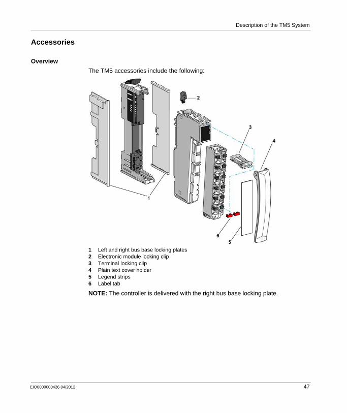
Overview
The TM5 accessories include the following:
1 Left and right bus base locking plates2 Electronic module locking clip3 Terminal locking clip4 Plain text cover holder5 Legend strips6 Label tab
NOTE: The controller is delivered with the right bus base locking plate.
EIO0000000426 04/2012 47
Description of the TM5 System
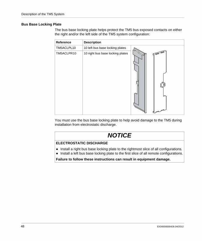
Bus Base Locking Plate
The bus base locking plate helps protect the TM5 bus exposed contacts on either the right and/or the left side of the TM5 system configuration:
You must use the bus base locking plate to help avoid damage to the TM5 during installation from electrostatic discharge.
Reference Description
TM5ACLPL10 10 left bus base locking plates
TM5ACLPR10 10 right bus base locking plates
NOTICEELECTROSTATIC DISCHARGE
Install a right bus base locking plate to the rightmost slice of all configurations.Install a left bus base locking plate to the first slice of all remote configurations.
Failure to follow these instructions can result in equipment damage.
48 EIO0000000426 04/2012
Description of the TM5 System
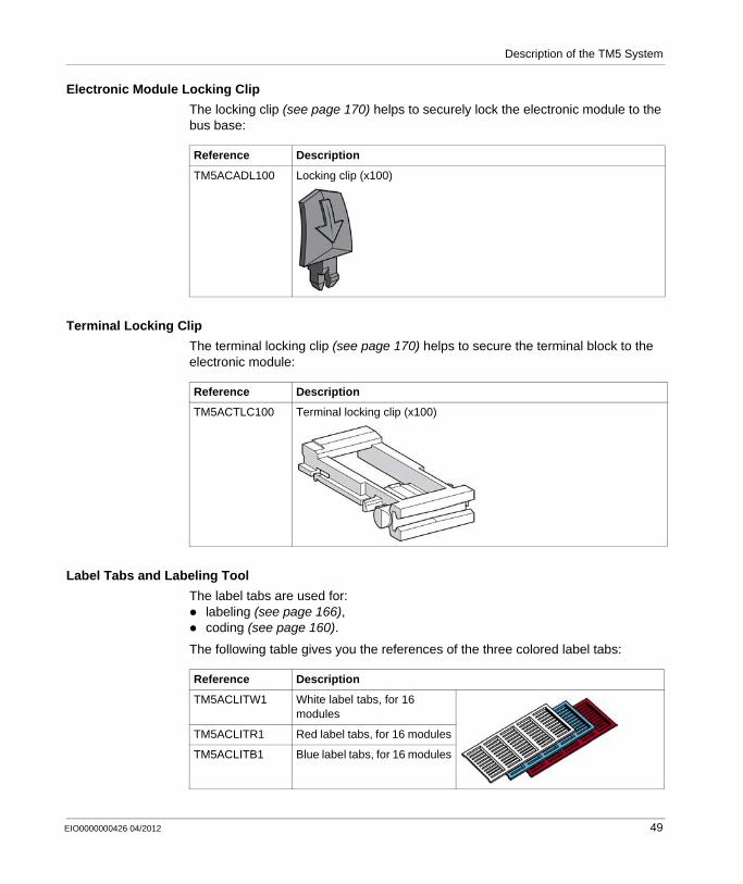
Electronic Module Locking Clip
The locking clip (see page 170) helps to securely lock the electronic module to the bus base:
Terminal Locking Clip
The terminal locking clip (see page 170) helps to secure the terminal block to the electronic module:
Label Tabs and Labeling Tool
The label tabs are used for:labeling (see page 166),coding (see page 160).
The following table gives you the references of the three colored label tabs:
Reference Description
TM5ACADL100 Locking clip (x100)
Reference Description
TM5ACTLC100 Terminal locking clip (x100)
Reference Description
TM5ACLITW1 White label tabs, for 16 modules
TM5ACLITR1 Red label tabs, for 16 modules
TM5ACLITB1 Blue label tabs, for 16 modules
EIO0000000426 04/2012 49
Description of the TM5 System
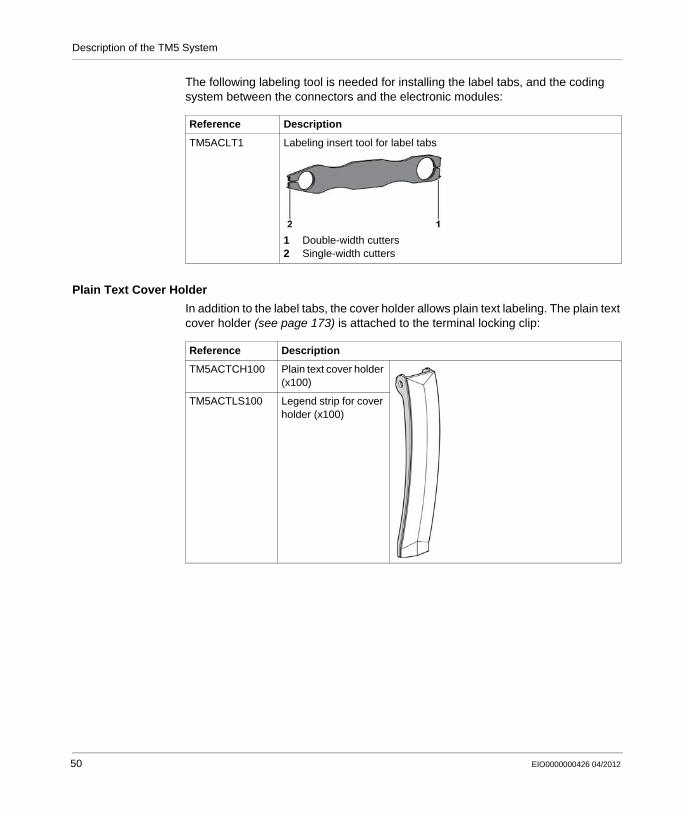
The following labeling tool is needed for installing the label tabs, and the coding system between the connectors and the electronic modules:
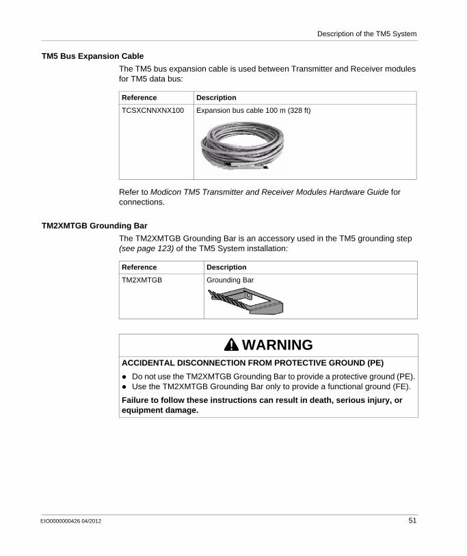
Plain Text Cover Holder
In addition to the label tabs, the cover holder allows plain text labeling. The plain text cover holder (see page 173) is attached to the terminal locking clip:
Reference Description
TM5ACLT1 Labeling insert tool for label tabs
1 Double-width cutters2 Single-width cutters
Reference Description
TM5ACTCH100 Plain text cover holder (x100)
TM5ACTLS100 Legend strip for cover holder (x100)
50 EIO0000000426 04/2012
Description of the TM5 System
TM5 Bus Expansion Cable
The TM5 bus expansion cable is used between Transmitter and Receiver modules for TM5 data bus:
Refer to Modicon TM5 Transmitter and Receiver Modules Hardware Guide for connections.
TM2XMTGB Grounding Bar
The TM2XMTGB Grounding Bar is an accessory used in the TM5 grounding step (see page 123) of the TM5 System installation:
Reference Description
TCSXCNNXNX100 Expansion bus cable 100 m (328 ft)
Reference Description
TM2XMTGB Grounding Bar
WARNINGACCIDENTAL DISCONNECTION FROM PROTECTIVE GROUND (PE)
Do not use the TM2XMTGB Grounding Bar to provide a protective ground (PE).Use the TM2XMTGB Grounding Bar only to provide a functional ground (FE).
Failure to follow these instructions can result in death, serious injury, or equipment damage.
EIO0000000426 04/2012 51

Description of the TM5 System
52 EIO0000000426 04/2012

EIO0000000426 04/2012
3
Modicon TM5 / TM7 Flexible System
Description of the TM7 System
EIO0000000426 04/2012
Description of the TM7 System
Overview
This chapter provides a brief description of the constituent parts of the TM7 System. It describes the field bus interface I/O block, the expansion block and the accessories.
What’s in this Chapter?
This chapter contains the following topics:
Topic Page
Field Bus Interface I/O Block Description 54
Expansion Blocks Description 57
Accessories 60
53
Description of the TM7 System
Field Bus Interface I/O Block Description
Field Bus Interface I/O Blocks
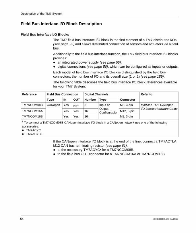
The TM7 field bus interface I/O block is the first element of a TM7 distributed I/Os (see page 22) and allows distributed connection of sensors and actuators via a field bus.
Additionally to the field bus interface function, the TM7 field bus interface I/O blocks provides:
an integrated power supply (see page 55).digital connections (see page 56), which can be configured as inputs or outputs.
Each model of field bus interface I/O block is distinguished by the field bus connectors, the number of I/O and its overall size (1 or 2) (see page 189).
The following table describes the field bus interface I/O block references available for your TM7 System:
If the CANopen interface I/O block is at the end of the line, connect a TM7ACTLA M12 CAN bus terminating resistor (see page 61):
to the accessory TM7ACYC• for a TM7NCOM08B.to the field bus OUT connector for a TM7NCOM16A or TM7NCOM16B.
Reference Field Bus Connection Digital Channels Refer to
Type IN OUT Number Type Connector
TM7NCOM08B CANopen Yes No1 8 Input or Output Configurable
M8, 3-pin Modicon TM7 CANopen I/O Blocks Hardware Guide
TM7NCOM16A Yes Yes 16 M12, 5-pin
TM7NCOM16B Yes Yes 16 M8, 3-pin
1 To connect a TM7NCOM08B CANopen interface I/O block in a CANopen network use one of the following accessories:
TM7ACYCTM7ACYCJ
54 EIO0000000426 04/2012
Description of the TM7 System
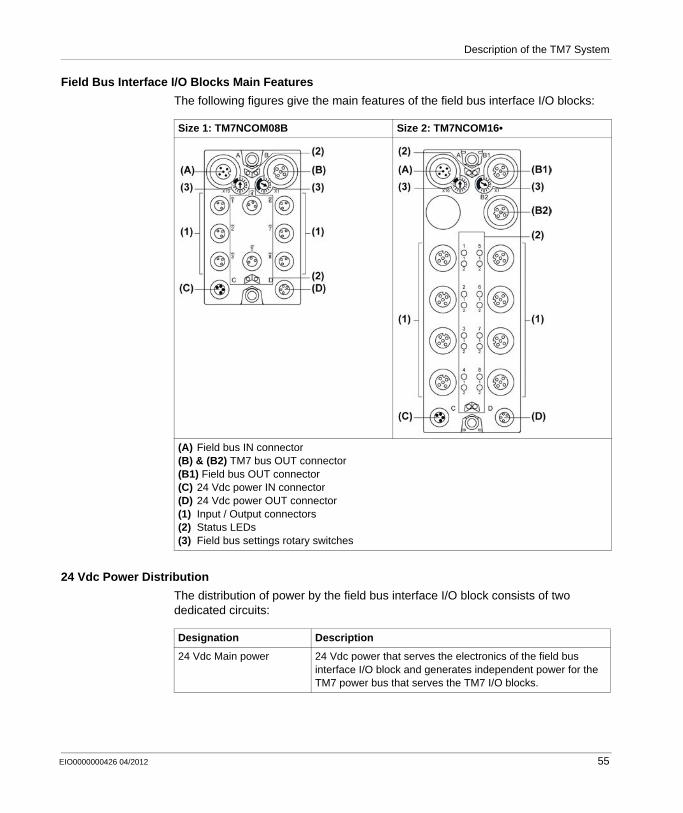
Field Bus Interface I/O Blocks Main Features
The following figures give the main features of the field bus interface I/O blocks:
24 Vdc Power Distribution
The distribution of power by the field bus interface I/O block consists of two dedicated circuits:
Size 1: TM7NCOM08B Size 2: TM7NCOM16•
(A) Field bus IN connector(B) & (B2) TM7 bus OUT connector(B1) Field bus OUT connector(C) 24 Vdc power IN connector(D) 24 Vdc power OUT connector(1) Input / Output connectors(2) Status LEDs(3) Field bus settings rotary switches
Designation Description
24 Vdc Main power 24 Vdc power that serves the electronics of the field bus interface I/O block and generates independent power for the TM7 power bus that serves the TM7 I/O blocks.
EIO0000000426 04/2012 55
Description of the TM7 System
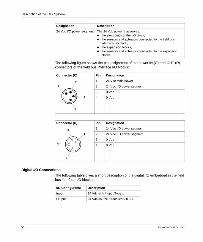
The following figure shows the pin assignment of the power IN (C) and OUT (D) connectors of the field bus interface I/O blocks:
Digital I/O Connections
The following table gives a short description of the digital I/O embedded in the field bus interface I/O blocks:
24 Vdc I/O power segment The 24 Vdc power that serves:the electronics of the I/O block,the sensors and actuators connected to the field bus interface I/O block,the expansion blocks,the sensors and actuators connected to the expansion blocks.
Connector (C) Pin Designation
1 24 Vdc Main power
2 24 Vdc I/O power segment
3 0 Vdc
4 0 Vdc
Connector (D) Pin Designation
1 24 Vdc I/O power segment
2 24 Vdc I/O power segment
3 0 Vdc
4 0 Vdc
Designation Description
12
3
4
12
3
4
I/O Configurable Description
Input 24 Vdc sink / input Type 1
Output 24 Vdc source / transistor / 0.5 A
56 EIO0000000426 04/2012

Description of the TM7 System
Expansion Blocks Description
Introduction
There are two main types of TM7 expansion blocks:TM7 Power Distribution Block (PDB) (see page 329)TM7 I/O block
Both the TM7 Power Distribution Blocks and TM7 I/O blocks make use of two power buses and a data bus to perform their functions. These buses are organized as follows:
TM7 bus: this bus includes one data bus and one power bus, named as follows:TM7 power bus: distributes power to supply the electronics of the TM7 I/O blocks. This bus receives its power from a TM5SBET7 Transmitter module. If necessary, the power on the TM7 power bus can be reinforced by adding a TM7 PDB.
TM7 data bus: passes data between the controller and the TM7 expansion blocks.
24 Vdc I/O power segment: distributes power to the inputs, outputs and the connected sensors and actuators of the TM7 I/O blocks. Each TM5 / TM7 System can have multiple 24 Vdc I/O power segments, depending on considerations such as power consumption and separation of I/O types.
I/O Block Main Features
Each I/O block reference is distinguished by its type and number of I/O and its physical size. TM7 I/O blocks come in two sizes, designated as size (1 or 2) (see page 189).
Reference Description Refer to
TM7BA•• Analog input, or output or mixed input and output block
Modicon TM7 Analog I/O Block Hardware Guide
TM7BD•• Digital input, or output or mixed input and output block
Modicon TM7 Digital I/O Block Hardware Guide
EIO0000000426 04/2012 57
Description of the TM7 System
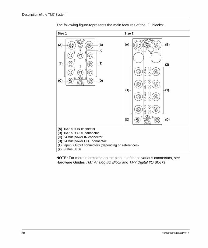
The following figure represents the main features of the I/O blocks:
NOTE: For more information on the pinouts of these various connectors, see Hardware Guides TM7 Analog I/O Block and TM7 Digital I/O Blocks
Size 1 Size 2
(A) TM7 bus IN connector(B) TM7 bus OUT connector(C) 24 Vdc power IN connector(D) 24 Vdc power OUT connector(1) Input / Output connectors (depending on references)(2) Status LEDs
58 EIO0000000426 04/2012
Description of the TM7 System
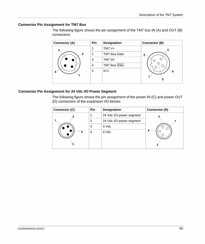
Connector Pin Assignment for TM7 Bus
The following figure shows the pin assignment of the TM7 bus IN (A) and OUT (B) connectors:
Connector Pin Assignment for 24 Vdc I/O Power Segment
The following figure shows the pin assignment of the power IN (C) and power OUT (D) connectors of the expansion I/O blocks:
Connector (A) Pin Designation Connector (B)
1 TM7 V+
2 TM7 Bus Data
3 TM7 0V
4 TM7 Bus Data
5 N.C.1
23
4 4
32
15
Connector (C) Pin Designation Connector (D)
1 24 Vdc I/O power segment
2 24 Vdc I/O power segment
3 0 Vdc
4 0 Vdc
12
3
4
12
3
4
EIO0000000426 04/2012 59
Description of the TM7 System
Accessories
Overview
The TM7 accessories include the following:useable with all expansion blocks:
M8 and M12 sealing plugs,support for block label,expansion bus, power distribution and sensor cables,torque wrench.
useable with analog temperature input blocks only:M12 thermocouple plug.
useable with the smaller size 1 expansion blocks:DIN rail mounting plate
useable with field bus interface I/O blocks only:CAN bus Y connector,CAN Y cableCAN bus cables,CAN bus terminating resistor.
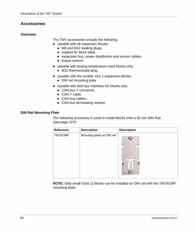
DIN Rail Mounting Plate
The following accessory is used to install blocks onto a 35 mm DIN Rail (see page 227):
NOTE: Only small (Size 1) blocks can be installed on DIN rail with the TM7ACMP mounting plate.
Reference Description Description
TM7ACMP Mounting plate on DIN rail
60 EIO0000000426 04/2012

Description of the TM7 System
Support For Block Label
The support for block labels allows labeling the blocks (see page 234):
M12 CAN Bus Terminating Resistor
The M12 CAN bus terminating resistor is connected on the last field bus interface I/O block of the CANopen network. It is connected:
to the accessory TM7ACYC• for a TM7NCOM08B.to the field bus OUT connector for a TM7NCOM16A or TM7NCOM16B.
M12 Thermocouple Plug
The M12 thermocouple plug is used for compensation of the temperature at measurement points:
Reference Description
TM7ACTLA M12 CAN bus terminating resistor
Reference Description
TM7ACTHA M12 thermocouple plug
EIO0000000426 04/2012 61
Description of the TM7 System
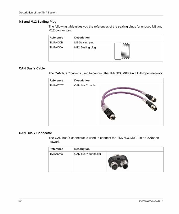
M8 and M12 Sealing Plug
The following table gives you the references of the sealing plugs for unused M8 and M12 connectors:
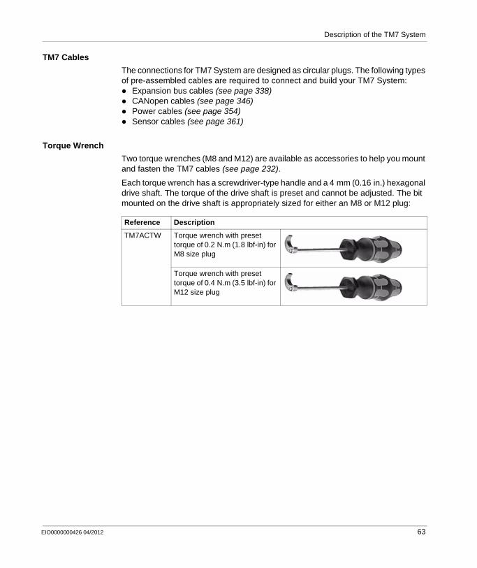
CAN Bus Y Cable
The CAN bus Y cable is used to connect the TM7NCOM08B in a CANopen network:
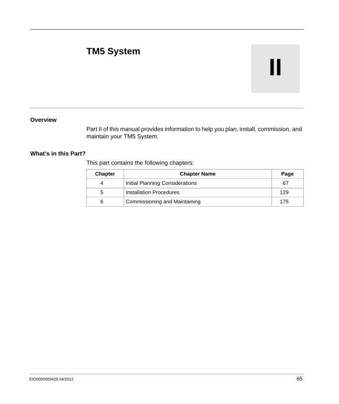
CAN Bus Y Connector
The CAN bus Y connector is used to connect the TM7NCOM08B in a CANopen network:
Reference Description
TM7ACCB M8 Sealing plug
TM7ACCA M12 Sealing plug
Reference Description
TM7ACYCJ CAN bus Y cable
Reference Description
TM7ACYC CAN bus Y connector
62 EIO0000000426 04/2012
Description of the TM7 System
TM7 Cables
The connections for TM7 System are designed as circular plugs. The following types of pre-assembled cables are required to connect and build your TM7 System:
Expansion bus cables (see page 338)CANopen cables (see page 346)Power cables (see page 354)Sensor cables (see page 361)
Torque Wrench
Two torque wrenches (M8 and M12) are available as accessories to help you mount and fasten the TM7 cables (see page 232).
Each torque wrench has a screwdriver-type handle and a 4 mm (0.16 in.) hexagonal drive shaft. The torque of the drive shaft is preset and cannot be adjusted. The bit mounted on the drive shaft is appropriately sized for either an M8 or M12 plug:
Reference Description
TM7ACTW Torque wrench with preset torque of 0.2 N.m (1.8 lbf-in) for M8 size plug
Torque wrench with preset torque of 0.4 N.m (3.5 lbf-in) for M12 size plug
EIO0000000426 04/2012 63

Description of the TM7 System
64 EIO0000000426 04/2012
EIO0000000426 04/2012
II
Modicon TM5 / TM7 Flexible System
TM5 System
EIO0000000426 04/2012
TM5 System
Overview
Part II of this manual provides information to help you plan, install, commission, and maintain your TM5 System.
What’s in this Part?
This part contains the following chapters:
Chapter Chapter Name Page
4 Initial Planning Considerations 67
5 Installation Procedures 129
6 Commissioning and Maintaining 175
65

TM5 System
66 EIO0000000426 04/2012

EIO0000000426 04/2012
4
Modicon TM5 / TM7 Flexible System
Planning
EIO0000000426 04/2012
Initial Planning Considerations
Overview
This chapter provides information that is helpful in the early planning stages for a TM5 System. It includes the requirements for enclosing the TM5 System in a protective housing and for determining the type of power supply source required for the configuration you choose.
What’s in this Chapter?
This chapter contains the following sections:
Section Topic Page
4.1 Operating Environment 68
4.2 Mechanical Requirements 71
4.3 TM5 Power System 84
4.4 Electrical Requirements 106
67

Planning
4.1 Operating Environment
Environmental Characteristics
Introduction
The following information describes the system-wide environmental requirements and characteristics for the TM5 System.
The general environmental characteristics are common to all components of the TM5 System.
Enclosure Requirements
TM5 components are designed as Zone B, Class A industrial equipment according to IEC/CISPR Publication 11. If they are used in environments other than those described in the standard, or in environments that do not meet the specifications in this manual, your ability to meet electromagnetic compatibility requirements in the presence of conducted and/or radiated interference may be reduced.
All TM5 components meet European Community (CE) requirements for open equipment as defined by EN61131-2. You must install them in an enclosure designed for the specific environmental conditions and to minimize the possibility of unintended contact with hazardous voltages. Your enclosure should be constructed of metal to improve the electromagnetic immunity of your TM5 System. Your enclosure should have a keyed locking mechanism to minimize unauthorized access.
Environmental Characteristics
This equipment meets UL, CSA, GOST-R and c-Tick certifications and CE requirements as indicated in the table below. This equipment is intended for use in a Pollution Degree 2 industrial environment.
The table below provides the general environmental characteristics:
Characteristic Specification
This product is compliant with Europe RoHS recommendations and China RoHS regulations.
Standard IEC61131-2 ed. 3 2007
Agencies UL 508CSA 22.2 No. 142-M1987CSA 22.2 No. 213-M1987
68 EIO0000000426 04/2012

Planning
NOTE: Replacement of the battery in the controllers other than with the type specified in this documentation may present a risk of fire or explosion. For more important information concerning the procedures for replacing lithium batteries, please consult the hardware guide for your controller.
Ambient operating temperature
Horizontal installation -10...60 ° C (14...140 ° F)1, 3
Vertical installation -10...50 ° C (14...122 ° F)3
Storage temperature -40...70 ° C (-40...158 ° F)2
Relative humidity 5...95% (non-condensing)
Degree of pollution IEC60664 2
Degree of protection
IEC61131-2 IP20
Corrosion immunity No
Operating altitude 0...2,000 m (0...6,560 ft.)
Storage altitude 0...3,000 m (0...9,842 ft.)
Vibration resistance
Mounted on a DIN rail 3.5 mm (0.138 in.) fixed amplitude from 5...8.4 Hz
9.8 m/s2 (1 gn) fixed acceleration from 8.4...150 Hz
Mechanical shock resistance 147 m/s2 (15 gn) for a duration of 11 ms
Connection type Removable spring terminal block
Connector insertion/removal cycles 50
Controller RTC Battery Type Renata Type CR2477 (replaceable)
Note:1 Some devices have temperature operating restrictions that require de-rating between
55 ° C and 60 ° C (131 ° F and 140 ° F), and may be subject to other possible restrictions. See the specific characteristics for your electronic module.
2 All controllers with a battery installed must be stored in the temperature range between -30...70 ° C (-22...158 ° F).
3 For compliance to Class I, Div 2 environment ratings, do not operate this device in locations with ambient temperatures less than 0 ° C (32° F).
Characteristic Specification
EIO0000000426 04/2012 69
Planning
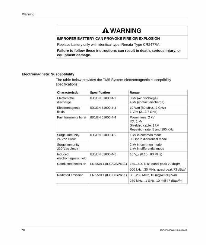
Electromagnetic Susceptibility
The table below provides the TM5 System electromagnetic susceptibility specifications:
WARNINGIMPROPER BATTERY CAN PROVOKE FIRE OR EXPLOSION
Replace battery only with identical type: Renata Type CR2477M.
Failure to follow these instructions can result in death, serious injury, or equipment damage.
Characteristic Specification Range
Electrostatic discharge
IEC/EN 61000-4-2 8 kV (air discharge)4 kV (contact discharge)
Electromagnetic fields
IEC/EN 61000-4-3 10 V/m (80 MHz...2 GHz)1 V/m (2...2.7 GHz)
Fast transients burst IEC/EN 61000-4-4 Power lines: 2 kVI/O: 1 kVShielded cable: 1 kVRepetition rate: 5 and 100 KHz
Surge immunity 24 Vdc circuit
IEC/EN 61000-4-5 1 kV in common mode0.5 kV in differential mode
Surge immunity 230 Vac circuit
2 kV in common mode1 kV in differential mode
Induced electromagnetic field
IEC/EN 61000-4-6 10 Veff (0.15...80 MHz)
Conducted emission EN 55011 (IEC/CISPR11) 150...500 kHz, quasi peak 79 dBµV
500 kHz...30 MHz, quasi peak 73 dBµV
Radiated emission EN 55011 (IEC/CISPR11) 30...230 MHz, 10 m@40 dBµV/m
230 MHz...1 GHz, 10 m@47 dBµV/m
70 EIO0000000426 04/2012
Planning
4.2 Mechanical Requirements
Introduction
This section provides information for enclosing the TM5 System in a protective housing.
What’s in this Section?
This section contains the following topics:
Topic Page
Enclosing the TM5 System 72
Mounting Positions 81
EIO0000000426 04/2012 71
Planning
Enclosing the TM5 System
Introduction
Components of the TM5 System are mounted "side by side". There is no space between the TM5 components.
The TM5 System components have an IP20 rating and must be enclosed. For optimal cooling and air circulation, an adequate clearance must be respected between your TM5 System (installed in the enclosure) and surrounding fixed objects (such as wire ducts and inside surfaces of the enclosure).
Size of the Enclosure
The size of the enclosure is determined by the number of expansion modules that are used with the controller, the field bus interface and any other auxiliary equipment. Spacing requirements (see page 74) must be included in determining the size of the enclosure.
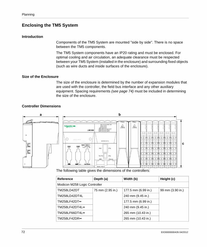
Controller Dimensions
The following table gives the dimensions of the controllers:
Reference Depth (a) Width (b) Height (c)
Modicon M258 Logic Controller
TM258LD42DT 75 mm (2.95 in.) 177.5 mm (6.99 in.) 99 mm (3.90 in.)
TM258LD42DT4L 240 mm (9.45 in.)
TM258LF42DT•• 177.5 mm (6.99 in.)
TM258LF42DT4L•• 240 mm (9.45 in.)
TM258LF66DT4L•• 265 mm (10.43 in.)
TM258LF42DR•• 265 mm (10.43 in.)
72 EIO0000000426 04/2012
Planning
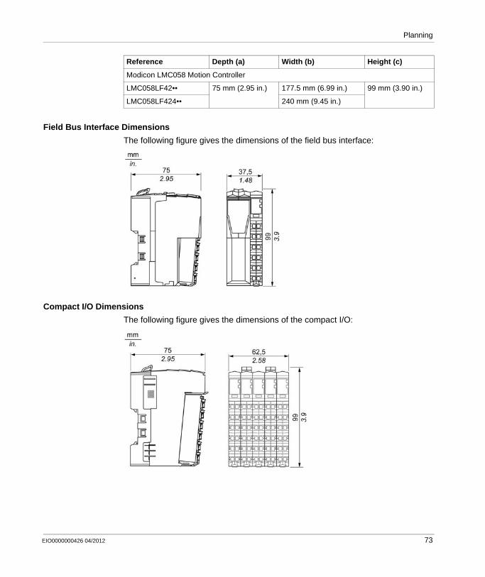
Field Bus Interface Dimensions
The following figure gives the dimensions of the field bus interface:
Compact I/O Dimensions
The following figure gives the dimensions of the compact I/O:
Modicon LMC058 Motion Controller
LMC058LF42•• 75 mm (2.95 in.) 177.5 mm (6.99 in.) 99 mm (3.90 in.)
LMC058LF424•• 240 mm (9.45 in.)
Reference Depth (a) Width (b) Height (c)
EIO0000000426 04/2012 73

Planning
Slice Dimensions
The following figure gives the dimensions of the slice:
Spacing Requirements
NOTE: Keep adequate spacing for proper ventilation and to maintain an ambient temperature as described in the environmental characteristics (see page 68).
Clearances must be respected when installing the product.
There are 3 types of clearances:Between the TM5 System and all sides of the cabinet (including the panel door). This type of clearance allows proper circulation of air around the TM5 System.Between the TM5 System terminal blocks and the wiring ducts. This distance helps avoid electromagnetic interference between the controller and the wiring ducts.Between the TM5 System and other heat generating devices installed in the same cabinet.
74 EIO0000000426 04/2012
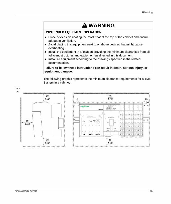
Planning
The following graphic represents the minimum clearance requirements for a TM5 System in a cabinet:
WARNINGUNINTENDED EQUIPMENT OPERATION
Place devices dissipating the most heat at the top of the cabinet and ensure adequate ventilation.Avoid placing this equipment next to or above devices that might cause overheating.Install the equipment in a location providing the minimum clearances from all adjacent structures and equipment as directed in this document.Install all equipment according to the drawings specified in the related documentation.
Failure to follow these instructions can result in death, serious injury, or equipment damage.
EIO0000000426 04/2012 75
Planning
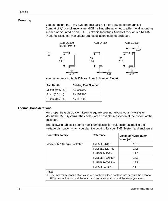
Mounting
You can mount the TM5 System on a DIN rail. For EMC (Electromagnetic Compatibility) compliance, a metal DIN rail must be attached to a flat metal mounting surface or mounted on an EIA (Electronic Industries Alliance) rack or in a NEMA (National Electrical Manufacturers Association) cabinet enclosure.
You can order a suitable DIN rail from Schneider Electric:
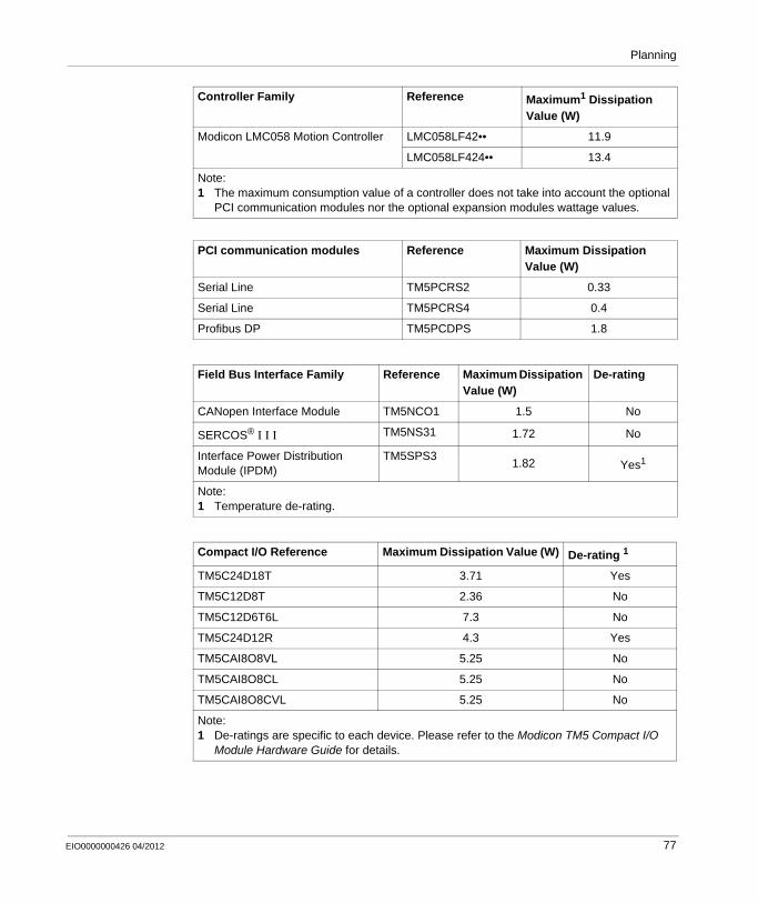
Thermal Considerations
For proper heat dissipation, keep adequate spacing around your TM5 System. Mount the TM5 System in the coolest area possible, most often at the bottom of the enclosure.
The following tables list some maximum dissipation values for estimating the wattage dissipation when you plan the cooling for your TM5 System and enclosure:
Rail Depth Catalog Part Number
15 mm (0.59 in.) AM1DE200
8 mm (0.31 in.) AM1DP200
15 mm (0.59 in.) AM1ED200
Controller Family Reference Maximum1 Dissipation Value (W)
Modicon M258 Logic Controller TM258LD42DT 12.3
TM258LD42DT4L 14.6
TM258LF42DT•• 12.5
TM258LF42DT4L•• 14.8
TM258LF66DT4L•• 18.2
TM258LF42DR•• 14.8
Note:1 The maximum consumption value of a controller does not take into account the optional
PCI communication modules nor the optional expansion modules wattage values.
76 EIO0000000426 04/2012
Planning
Modicon LMC058 Motion Controller LMC058LF42•• 11.9
LMC058LF424•• 13.4
PCI communication modules Reference Maximum Dissipation Value (W)
Serial Line TM5PCRS2 0.33
Serial Line TM5PCRS4 0.4
Profibus DP TM5PCDPS 1.8
Field Bus Interface Family Reference Maximum Dissipation Value (W)
De-rating
CANopen Interface Module TM5NCO1 1.5 No
SERCOS® Ι Ι Ι TM5NS31 1.72 No
Interface Power Distribution Module (IPDM)
TM5SPS31.82 Yes1
Note:1 Temperature de-rating.
Compact I/O Reference Maximum Dissipation Value (W) De-rating 1
TM5C24D18T 3.71 Yes
TM5C12D8T 2.36 No
TM5C12D6T6L 7.3 No
TM5C24D12R 4.3 Yes
TM5CAI8O8VL 5.25 No
TM5CAI8O8CL 5.25 No
TM5CAI8O8CVL 5.25 No
Note:1 De-ratings are specific to each device. Please refer to the Modicon TM5 Compact I/O
Module Hardware Guide for details.
Controller Family Reference Maximum1 Dissipation Value (W)
Note:1 The maximum consumption value of a controller does not take into account the optional
PCI communication modules nor the optional expansion modules wattage values.
EIO0000000426 04/2012 77
Planning
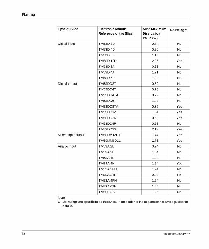
Type of Slice Electronic Module Reference of the Slice
Slice Maximum Dissipation Value (W)
De-rating 1
Digital input TM5SDI2D 0.54 No
TM5SDI4D 0.86 No
TM5SDI6D 1.16 No
TM5SDI12D 2.06 Yes
TM5SDI2A 0.82 No
TM5SDI4A 1.21 No
TM5SDI6U 1.02 No
Digital output TM5SDO2T 0.59 No
TM5SDO4T 0.78 No
TM5SDO4TA 0.79 No
TM5SDO6T 1.02 No
TM5SDO8TA 0.35 Yes
TM5SDO12T 1.54 Yes
TM5SDO2R 0.58 Yes
TM5SDO4R 0.93 No
TM5SDO2S 2.13 Yes
Mixed input/output TM5SDM12DT 1.44 Yes
TM5SMM6D2L 1.75 Yes
Analog input TM5SAI2L 0.94 No
TM5SAI2H 1.34 No
TM5SAI4L 1.24 No
TM5SAI4H 1.64 Yes
TM5SAI2PH 1.24 No
TM5SAI2TH 0.86 No
TM5SAI4PH 1.24 No
TM5SAI6TH 1.05 No
TM5SEAISG 1.25 No
Note:1 De-ratings are specific to each device. Please refer to the expansion hardware guides for
details.
78 EIO0000000426 04/2012
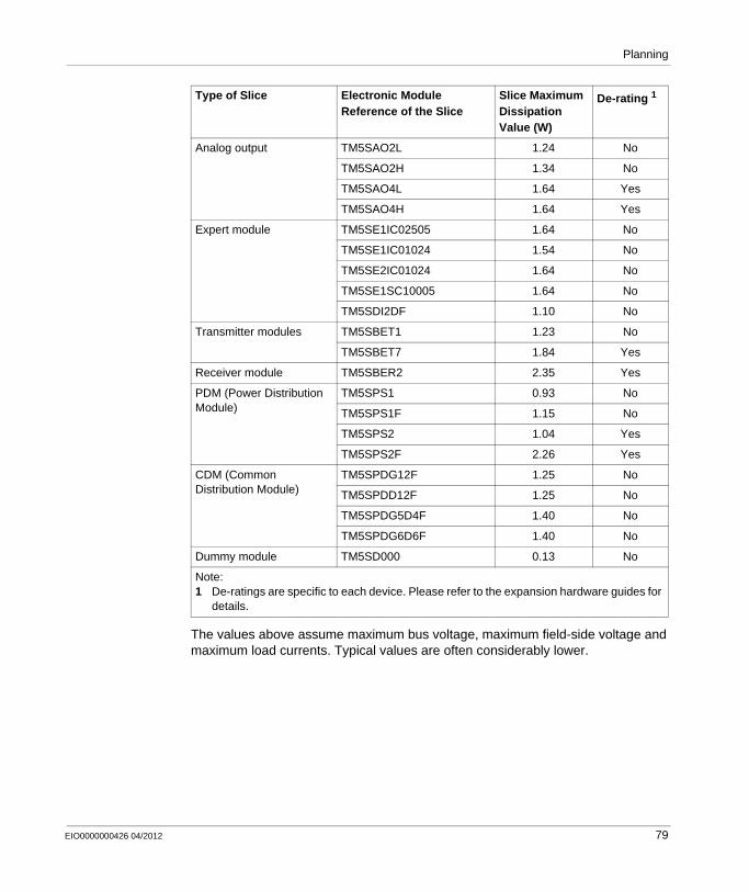
Planning
The values above assume maximum bus voltage, maximum field-side voltage and maximum load currents. Typical values are often considerably lower.
Analog output TM5SAO2L 1.24 No
TM5SAO2H 1.34 No
TM5SAO4L 1.64 Yes
TM5SAO4H 1.64 Yes
Expert module TM5SE1IC02505 1.64 No
TM5SE1IC01024 1.54 No
TM5SE2IC01024 1.64 No
TM5SE1SC10005 1.64 No
TM5SDI2DF 1.10 No
Transmitter modules TM5SBET1 1.23 No
TM5SBET7 1.84 Yes
Receiver module TM5SBER2 2.35 Yes
PDM (Power Distribution Module)
TM5SPS1 0.93 No
TM5SPS1F 1.15 No
TM5SPS2 1.04 Yes
TM5SPS2F 2.26 Yes
CDM (Common Distribution Module)
TM5SPDG12F 1.25 No
TM5SPDD12F 1.25 No
TM5SPDG5D4F 1.40 No
TM5SPDG6D6F 1.40 No
Dummy module TM5SD000 0.13 No
Type of Slice Electronic Module Reference of the Slice
Slice Maximum Dissipation Value (W)
De-rating 1
Note:1 De-ratings are specific to each device. Please refer to the expansion hardware guides for
details.
EIO0000000426 04/2012 79
Planning
NOTE: Keep adequate spacing for proper ventilation and to maintain an ambient temperature. Maximum ambient temperature depends on the mounting position.
WARNINGUNINTENDED EQUIPMENT OPERATION
Place devices dissipating the most heat at the top of the cabinet and ensure adequate ventilation.Avoid placing this equipment next to or above devices that might cause overheating.Install the equipment in a location providing the minimum clearances from all adjacent structures and equipment as directed in this document.Install all equipment according to the drawings specified in the related documentation.
Failure to follow these instructions can result in death, serious injury, or equipment damage.
80 EIO0000000426 04/2012
Planning
Mounting Positions
Introduction
This section shows the correct mounting positions for the TM5 System.
Local, remote and distributed configurations follow the same rules.
The TM5 System should only be positioned as shown in the correct (see page 81) or acceptable (see page 81) mounting position figures.
Correct Mounting Position
The TM5 System must be mounted horizontally on a vertical plane as shown in the figures below:
NOTE: Keep adequate spacing for proper ventilation and to maintain an ambient temperature as described in the environmental characteristics (see page 68).
Acceptable Mounting Positions
Whenever possible, the TM5 System should only be positioned as shown in the figure above.
EIO0000000426 04/2012 81
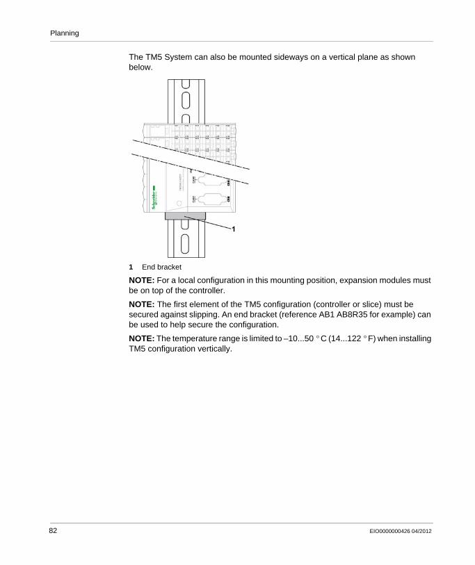
Planning
The TM5 System can also be mounted sideways on a vertical plane as shown below.
1 End bracket
NOTE: For a local configuration in this mounting position, expansion modules must be on top of the controller.
NOTE: The first element of the TM5 configuration (controller or slice) must be secured against slipping. An end bracket (reference AB1 AB8R35 for example) can be used to help secure the configuration.
NOTE: The temperature range is limited to –10...50 ° C (14...122 ° F) when installing TM5 configuration vertically.
82 EIO0000000426 04/2012

Planning
Incorrect Mounting Position
The figures below show incorrect mounting positions:
EIO0000000426 04/2012 83
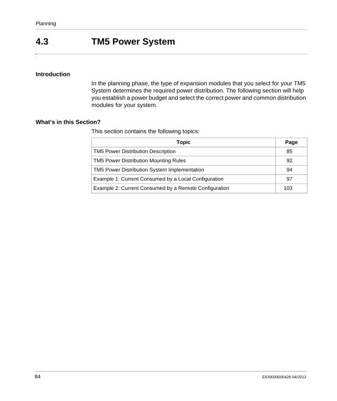
Planning
4.3 TM5 Power System
Introduction
In the planning phase, the type of expansion modules that you select for your TM5 System determines the required power distribution. The following section will help you establish a power budget and select the correct power and common distribution modules for your system.
What’s in this Section?
This section contains the following topics:
Topic Page
TM5 Power Distribution Description 85
TM5 Power Distribution Mounting Rules 92
TM5 Power Distribution System Implementation 94
Example 1: Current Consumed by a Local Configuration 97
Example 2: Current Consumed by a Remote Configuration 103
84 EIO0000000426 04/2012
Planning
TM5 Power Distribution Description
Power Distribution Overview
The first (leftmost) component in the local (see page 19), remote (see page 20) and distributed (see page 21) configurations of the TM5 System distributes power for the 24 Vdc I/O power segment and generates power for the TM5 power bus. There are other components that distribute power to create separate 24 Vdc I/O power segments, and others that distribute power and additionally generate supplemental power to the TM5 power bus.
The Controller Power Distribution Module (CPDM) is the beginning of the power distribution for the local configuration.
The TM5SBER2 Receiver module is the beginning of the power distribution for the remote configuration.
The TM5SBET7 Transmitter module (see page 195) is the beginning of the power distribution for the TM7 power bus.
The Interface Power Distribution Module (IPDM) of the field bus interface is the beginning of the power distribution for the distributed configuration.
Where and when needed, Power Distribution Modules (PDM) could be added to:Divide the 24 Vdc I/O power segment into several separated 24 Vdc I/O power segments, or;Divide the 24 Vdc I/O power segment into several separated 24 Vdc I/O power segments and provide supplementary power to the TM5 power bus if required by your I/O configuration.
EIO0000000426 04/2012 85
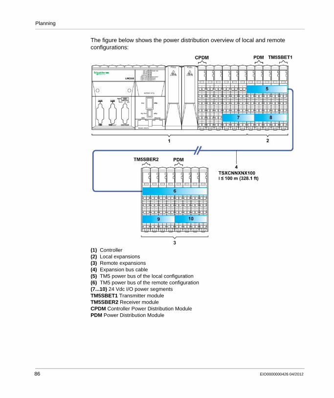
Planning
The figure below shows the power distribution overview of local and remote configurations:
(1) Controller(2) Local expansions(3) Remote expansions(4) Expansion bus cable(5) TM5 power bus of the local configuration(6) TM5 power bus of the remote configuration(7...10) 24 Vdc I/O power segmentsTM5SBET1 Transmitter moduleTM5SBER2 Receiver moduleCPDM Controller Power Distribution ModulePDM Power Distribution Module
86 EIO0000000426 04/2012
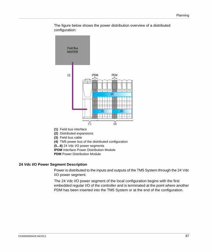
Planning
The figure below shows the power distribution overview of a distributed configuration:
(1) Field bus interface(2) Distributed expansions(3) Field bus cable(4) TM5 power bus of the distributed configuration(5...6) 24 Vdc I/O power segmentsIPDM Interface Power Distribution ModulePDM Power Distribution Module
24 Vdc I/O Power Segment Description
Power is distributed to the inputs and outputs of the TM5 System through the 24 Vdc I/O power segment.
The 24 Vdc I/O power segment of the local configuration begins with the first embedded regular I/O of the controller and is terminated at the point where another PDM has been inserted into the TM5 System or at the end of the configuration.
EIO0000000426 04/2012 87
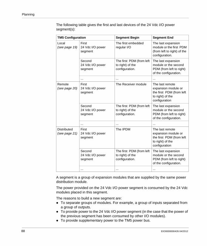
Planning
The following table gives the first and last devices of the 24 Vdc I/O power segment(s):
A segment is a group of expansion modules that are supplied by the same power distribution module.
The power provided on the 24 Vdc I/O power segment is consumed by the 24 Vdc modules placed in this segment.
The reasons to build a new segment are:To separate groups of modules. For example, a group of inputs separated from a group of outputs.To provide power to the 24 Vdc I/O power segment (in the case that the power of the previous segment has been consumed by other I/O modules).To provide supplementary power to the TM5 power bus.
TM5 Configuration Segment Begin Segment End
Local (see page 19)
First24 Vdc I/O power segment
The first embedded regular I/O
The last expansion module or the first PDM (from left to right) of the configuration.
Second24 Vdc I/O power segment
The first PDM (from left to right) of the configuration.
The last expansion module or the second PDM (from left to right) of the configuration.
... ... ...
Remote (see page 20)
First24 Vdc I/O power segment
The Receiver module The last remote expansion module or the first PDM (from left to right) of the configuration
Second24 Vdc I/O power segment
The first PDM (from left to right) of the configuration.
The last expansion module or the second PDM (from left to right) of the configuration.
... ... ...
Distributed (see page 21)
First24 Vdc I/O power segment
The IPDM The last remote expansion module or the first PDM (from left to right) of the configuration
Second24 Vdc I/O power segment
The first PDM (from left to right) of the configuration.
The last expansion module or the second PDM (from left to right) of the configuration.
... ... ...
88 EIO0000000426 04/2012
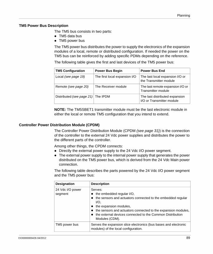
Planning
TM5 Power Bus Description
The TM5 bus consists in two parts:TM5 data busTM5 power bus
The TM5 power bus distributes the power to supply the electronics of the expansion modules of a local, remote or distributed configuration. If needed the power on the TM5 bus can be reinforced by adding specific PDMs depending on the reference.
The following table gives the first and last devices of the TM5 power bus:
NOTE: The TM5SBET1 transmitter module must be the last electronic module in either the local or remote TM5 configuration that you intend to extend.
Controller Power Distribution Module (CPDM)
The Controller Power Distribution Module (CPDM (see page 31)) is the connection of the controller to the external 24 Vdc power supplies and distributes the power to the different parts of the controller.
Among other things, the CPDM connects:Directly the external power supply to the 24 Vdc I/O power segment.The external power supply to the internal power supply that generates the power distributed on the TM5 power bus, which is derived from the 24 Vdc Main power connection.
The following table describes the parts powered by the 24 Vdc I/O power segment and the TM5 power bus:
TM5 Configuration Power Bus Begin Power Bus End
Local (see page 19) The first local expansion I/O The last local expansion I/O or the Transmitter module
Remote (see page 20) The Receiver module The last remote expansion I/O or Transmitter module
Distributed (see page 21) The IPDM The last distributed expansion I/O or Transmitter module
Designation Description
24 Vdc I/O power segment
Serves:the embedded regular I/O,the sensors and actuators connected to the embedded regular I/O,the expansion modules,the sensors and actuators connected to the expansion modules,the external devices connected to the Common Distribution Modules (CDM).
TM5 power bus Serves the expansion slice electronics (bus bases and electronic modules) of the local configuration.
EIO0000000426 04/2012 89

Planning
Interface Power Distribution Module (IPDM)
The Interface Power Distribution Module (IPDM (see page 37)) is the connection of the field bus interface to the external 24 Vdc power supplies.
Among other things, the IPDM connects:Directly the external power supply to the 24 Vdc I/O power segment.The external power supply to the internal power supply that generates the power distributed on the TM5 power bus, which is derived from the 24 Vdc Main power connection.
The following table describes the parts powered by the 24 Vdc I/O power segment and the TM5 power bus:
Receiver Module (TM5SBER2)
The TM5SBER2 integrates an electronic power supply that generates the power distributed by the TM5 power bus.
It also connects the external 24 Vdc power supply to the 24 Vdc I/O power segment.
The following table describes the parts powered by the 24 Vdc I/O power segment and the TM5 power bus:
Designation Description
24 Vdc I/O power segment
Serves:the distributed expansion modules,the sensors and actuators connected to the distributed expansion modules,the external devices connected to the Common Distribution Modules (CDM) of the distributed configuration.
TM5 power bus Serves the electronic of the expansions (bus bases and electronic modules) of the distributed configuration.
Designation Description
24 Vdc I/O power segment
Serves:the remote expansion modules,the sensors and actuators connected to the remote expansion modules,the external devices connected to the Common Distribution Modules (CDM) of the remote configuration.
TM5 power bus Serves the electronic of the expansions (bus bases and electronic modules).
90 EIO0000000426 04/2012
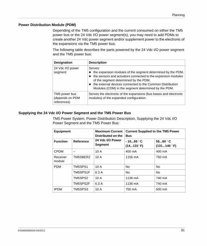
Planning
Power Distribution Module (PDM)
Depending of the TM5 configuration and the current consumed on either the TM5 power bus or the 24 Vdc I/O power segment(s), you may need to add PDMs to create another 24 Vdc power segment and/or supplement power to the electronic of the expansions via the TM5 power bus.
The following table describes the parts powered by the 24 Vdc I/O power segment and the TM5 power bus:
Supplying the 24 Vdc I/O Power Segment and the TM5 Power Bus
TM5 Power System, Power Distribution Description, Supplying the 24 Vdc I/O Power Segment and the TM5 Power Bus:
Designation Description
24 Vdc I/O power segment
Serves:the expansion modules of the segment determined by the PDM,the sensors and actuators connected to the expansion modules of the segment determined by the PDM,the external devices connected to the Common Distribution Modules (CDM) in the segment determined by the PDM.
TM5 power bus (depends on PDM references)
Serves the electronic of the expansions (bus bases and electronic modules) of the expanded configuration.
Equipment Maximum Current Distributed on the 24 Vdc I/O Power Segment
Current Supplied to the TM5 Power Bus
Function Reference - 10...55 ° C (14...131° F)
55...60 ° C (131...140 ° F)
CPDM – 10 A 400 mA 400 mA
Receiver module
TM5SBER2 10 A 1156 mA 750 mA
PDM TM5SPS1 10 A No No
TM5SPS1F 6.3 A No No
TM5SPS2 10 A 1136 mA 740 mA
TM5SPS2F 6.3 A 1136 mA 740 mA
IPDM TM5SPS3 10 A 750 mA 500 mA
EIO0000000426 04/2012 91
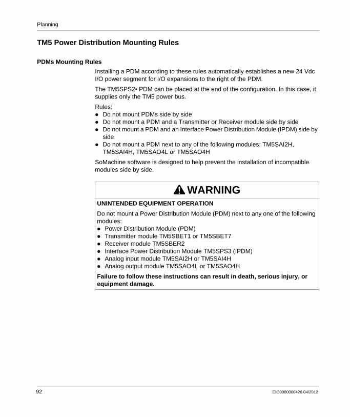
Planning
TM5 Power Distribution Mounting Rules
PDMs Mounting Rules
Installing a PDM according to these rules automatically establishes a new 24 Vdc I/O power segment for I/O expansions to the right of the PDM.
The TM5SPS2• PDM can be placed at the end of the configuration. In this case, it supplies only the TM5 power bus.
Rules:Do not mount PDMs side by sideDo not mount a PDM and a Transmitter or Receiver module side by sideDo not mount a PDM and an Interface Power Distribution Module (IPDM) side by sideDo not mount a PDM next to any of the following modules: TM5SAI2H, TM5SAI4H, TM5SAO4L or TM5SAO4H
SoMachine software is designed to help prevent the installation of incompatible modules side by side.
WARNINGUNINTENDED EQUIPMENT OPERATION
Do not mount a Power Distribution Module (PDM) next to any one of the following modules:
Power Distribution Module (PDM)Transmitter module TM5SBET1 or TM5SBET7Receiver module TM5SBER2Interface Power Distribution Module TM5SPS3 (IPDM)Analog input module TM5SAI2H or TM5SAI4HAnalog output module TM5SAO4L or TM5SAO4H
Failure to follow these instructions can result in death, serious injury, or equipment damage.
92 EIO0000000426 04/2012
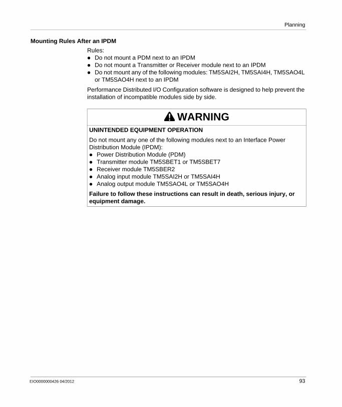
Planning
Mounting Rules After an IPDM
Rules:Do not mount a PDM next to an IPDMDo not mount a Transmitter or Receiver module next to an IPDMDo not mount any of the following modules: TM5SAI2H, TM5SAI4H, TM5SAO4L or TM5SAO4H next to an IPDM
Performance Distributed I/O Configuration software is designed to help prevent the installation of incompatible modules side by side.
WARNINGUNINTENDED EQUIPMENT OPERATION
Do not mount any one of the following modules next to an Interface Power Distribution Module (IPDM):
Power Distribution Module (PDM)Transmitter module TM5SBET1 or TM5SBET7Receiver module TM5SBER2Analog input module TM5SAI2H or TM5SAI4HAnalog output module TM5SAO4L or TM5SAO4H
Failure to follow these instructions can result in death, serious injury, or equipment damage.
EIO0000000426 04/2012 93

Planning
TM5 Power Distribution System Implementation
Power Distribution Planning
The power distribution system supplies the 24 Vdc I/O power segment and the TM5 power bus for local, remote and distributed configurations.
The planning of your TM5 power distribution system should follow this order:
To plan the power distribution of the TM5 System you must calculate the:Current consumption on the 24 Vdc I/O power segment(s)Current consumption on the TM5 power bus segment or segments in the case of remote configurations(s).
Current Consumed on the 24 Vdc I/O Power Segment
The current consumed on the 24 Vdc I/O power segment is composed of
The current consumed by the electronic modules1.The current consumed by the loads connected to the DC outputs of the modules supplied by the 24 Vdc I/O power segment.The current consumed to supply the sensors and actuators connected to the electronics modules.The current consumed to supply external devices connected to the Common Distribution Modules (CDM)
Note:1 For the electronics modules with 24 Vdc inputs, this current includes the input
signal currents for all inputs in activated state.
Step Description
1 Plan your TM5 System (controller and expansion modules, remote and distributed islands).
2 (Optionally) Create some 24 Vdc power segments by adding PDM type TM5SPS1•, for example, to separate the input slices from output slices. Another example is to separate the AC slices from DC slices.
3 Calculate the current consumed on each 24 Vdc I/O power and insert additional PDM type TM5SPS1• to create segments where and when needed.
4 Calculate the current consumed on the TM5 power bus segment(s) and replace PDM type TM5SPS1• with type TM5SPS2• or provide additional PDM type TM5SPS2• where and when needed.
94 EIO0000000426 04/2012

Planning
The following figure shows how the 24 Vdc I/O power segment is created, and power is distributed, by the association of the I/O slices:
1 Bus base2 Electronic module3 Terminal blockA DC Input or output slicesB DC Input slices with sensor supplyC DC Output slices with actuator supplyD CDM with external device
EIO0000000426 04/2012 95
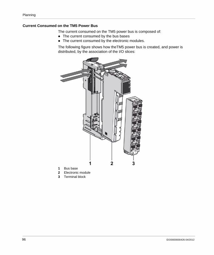
Planning
Current Consumed on the TM5 Power Bus
The current consumed on the TM5 power bus is composed of:The current consumed by the bus basesThe current consumed by the electronic modules.
The following figure shows how theTM5 power bus is created, and power is distributed, by the association of the I/O slices:
1 Bus base2 Electronic module3 Terminal block
96 EIO0000000426 04/2012
Planning
Example 1: Current Consumed by a Local Configuration
Introduction
This first example is for a local configuration (controller and its local expansion modules). A later example (see page 103) is based on a remote configuration (TM5 Receiver module and its remote expansion modules). From these examples, you should be able to make the calculations necessary for your TM5 System.
In a local configuration, the Controller Power Distribution Module (CPDM) connects:directly the external power supply to the 24 Vdc I/O power segment.the external power supply to the internal power supply that generates the power distributed on the TM5 power bus, which is derived from the 24 Vdc Main power connection.
All current consumption values are documented in the TM5 Consumption Table (see page 250).
Planning Example
This configuration example includes:The controller TM258LF42DT equipped with embedded DI12DE and DO12TE electronic modules.Some expansion modules:
TM5SAI4LTM5SDI12DTM5SDI4DTM5SDM12DTTM5SDI4ATM5SDO4TATM5SDO12TTM5SDO2TTM5SDO2R
Assumptions used for the purposes of calculating the consumption of this example:CPDM: The maximum current distributed on the 24 Vdc I/O power segment is
limited by an external isolated power supply of 6300 mA.DO12TE: Only 50 % of the outputs are active at any given time, and that the
maximum current draw of any given output is 500 mA, or 3000 mA total for the module.
TM5SDI4D: The current to supply the electronic sensors of this example has been estimated at 50 mA per sensor, or 200 mA total for the module.
TM5SDM12DT: The sum of the current draw for all outputs connected to the module is never more than 1500 mA at any given time.
TM5SDO12T: Only 50% of the outputs are active at any given time, and that the maximum current draw of any given output is 500 mA, or 3000 mA total for the module.
EIO0000000426 04/2012 97
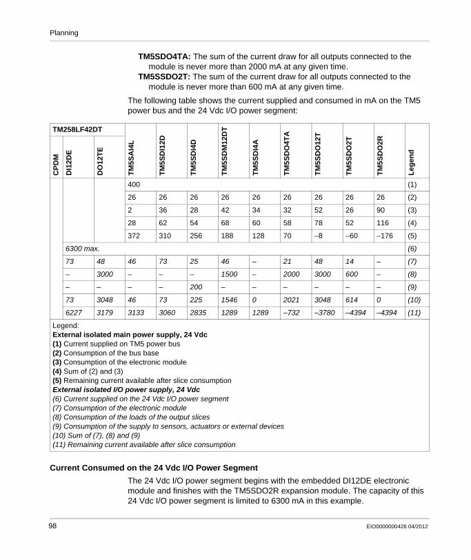
Planning
TM5SDO4TA: The sum of the current draw for all outputs connected to the module is never more than 2000 mA at any given time.
TM5SSDO2T: The sum of the current draw for all outputs connected to the module is never more than 600 mA at any given time.
The following table shows the current supplied and consumed in mA on the TM5 power bus and the 24 Vdc I/O power segment:
Current Consumed on the 24 Vdc I/O Power Segment
The 24 Vdc I/O power segment begins with the embedded DI12DE electronic module and finishes with the TM5SDO2R expansion module. The capacity of this 24 Vdc I/O power segment is limited to 6300 mA in this example.
TM258LF42DTT
M5S
AI4
L
TM
5SD
I12D
TM
5SD
I4D
TM
5SD
M12
DT
TM
5SD
I4A
TM
5SD
O4T
A
TM
5SD
O12
T
TM
5SD
O2T
TM
5SD
O2R
Leg
end
CP
DM
DI1
2DE
DO
12T
E
400 (1)
26 26 26 26 26 26 26 26 26 (2)
2 36 28 42 34 32 52 26 90 (3)
28 62 54 68 60 58 78 52 116 (4)
372 310 256 188 128 70 –8 –60 –176 (5)
6300 max. (6)
73 48 46 73 25 46 – 21 48 14 – (7)
– 3000 – – – 1500 – 2000 3000 600 – (8)
– – – – 200 – – – – – – (9)
73 3048 46 73 225 1546 0 2021 3048 614 0 (10)
6227 3179 3133 3060 2835 1289 1289 –732 –3780 –4394 –4394 (11)
Legend:External isolated main power supply, 24 Vdc (1) Current supplied on TM5 power bus(2) Consumption of the bus base(3) Consumption of the electronic module(4) Sum of (2) and (3)(5) Remaining current available after slice consumptionExternal isolated I/O power supply, 24 Vdc (6) Current supplied on the 24 Vdc I/O power segment(7) Consumption of the electronic module(8) Consumption of the loads of the output slices(9) Consumption of the supply to sensors, actuators or external devices(10) Sum of (7), (8) and (9)(11) Remaining current available after slice consumption
98 EIO0000000426 04/2012

Planning
In this example, the total current consumed on the 24 Vdc I/O power segment is 10694 mA and exceeds the 6300 mA capacity of this segment.
This requires you to divide the existing segment into two segments by adding a PDM. For this example, a TM5SPS1F (internal fuse of 6300 mA max.) between the TM5SDI4A and TM5SDO4TA electronic modules is needed.
The first 24 Vdc I/O power segment begins with the embedded DI12DE module and finishes with the TM5SDI4A expansion module once the PDM is installed.
The second 24 Vdc I/O power segment begins with the TM5SPS1F PDM and finishes with the TM5SDO2R expansion module.
The following table shows, the current supplied and consumed in mA on the 24 Vdc I/O power segment after the addition of the PDM:
TM258LF42DT
TM
5SA
I4L
TM
5SD
I12D
TM
5SD
I4D
TM
5SD
M12
DT
TM
5SD
I4A
TM
5SP
1F
TM
5SD
O4T
A
TM
5SD
O12
T
TM
5SD
O2T
TM
5SD
O2R
Leg
end
CP
DM
DI1
2DE
DO
12T
E
400 (1)
26 26 26 26 26 26 26 26 26 26 (2)
2 36 28 42 34 40 32 52 26 90 (3)
28 62 54 68 60 66 58 78 52 116 (4)
372 310 256 188 128 62 4 –74 –126 –242 (5)
6300 max. 6300 max. (6)
73 48 46 73 25 46 – 25 21 48 14 – (7)
– 3000 – – – 1500 – – 2000 3000 600 – (8)
– – – – 200 – – – – – – – (9)
73 3048 46 73 225 1546 0 25 2021 3048 614 0 (10)
6227 3179 3133 3060 2835 1289 1289 6275 4254 1206 592 592 (11)
Legend:External isolated main power supply, 24 Vdc (1) Current supplied on TM5 power bus(2) Consumption of the bus base(3) Consumption of the electronic module(4) Sum of (2) and (3)(5) Remaining current available after slice consumptionExternal isolated I/O power supply, 24 Vdc (6) Current supplied on the 24 Vdc I/O power segment(7) Consumption of the electronic module(8) Consumption of the loads of the output slices(9) Consumption of the supply to sensors, actuators or external devices(10) Sum of (7), (8) and (9)(11) Remaining current available after slice consumption
EIO0000000426 04/2012 99
Planning
The total current consumed on the first 24 Vdc I/O power segment is 5011 mA and does not exceed the 6300 mA capacity of this segment.
The total current consumed on the second 24 Vdc I/O power segment is 5708 mA and does not exceed the 6300 mA capacity of that segment.
The next step is to calculate the current consumed on the TM5 power bus to validate the configuration of this example.
Current Consumed on the TM5 Power Bus
The controller generates 400 mA on the TM5 power bus to supply expansion slices. The TM5 power bus begins with the TM5SAI4L expansion module and terminates with the TM5SDO2R expansion module.
100 EIO0000000426 04/2012

Planning
The following table shows, the current supplied and consumed in mA on the TM5 power bus:
The total current consumed on the TM5 power bus is 642 mA, and exceeds the 400 mA capacity of the segment.
You must supplement the TM5 power bus by substituting the TM5SPS1F PDM with a TM5SPS2F type PDM .
The CPDM and the TM5SPS2F PDM provide 1576 mA (400 mA + 1176 mA) of current to the TM5 power bus.
TM258LF42DT
TM
5SA
I4L
TM
5SD
I12D
TM
5SD
I4D
TM
5SD
M12
DT
TM
5SD
I4A
TM
5SP
1F
TM
5SD
O4T
A
TM
5SD
O12
T
TM
5SD
O2T
TM
5SD
O2R
Leg
end
CP
DM
DI1
2DE
DO
12T
E
400 (1)
26 26 26 26 26 26 26 26 26 26 (2)
2 36 28 42 34 40 32 52 26 90 (3)
28 62 54 68 60 66 58 78 52 116 (4)
372 310 256 188 128 62 4 –74 –126 –242 (5)
6300 max. 6300 max. (6)
73 48 46 73 25 46 – 25 21 48 14 – (7)
– 3000 – – – 1500 – – 2000 3000 600 – (8)
– – – – 200 – – – – – – – (9)
73 3048 46 73 225 1546 0 25 2021 3048 614 0 (10)
6227 3179 3133 3060 2835 1289 1289 6275 4254 1206 592 592 (11)
Legend:External isolated main power supply, 24 Vdc (1) Current supplied on TM5 power bus(2) Consumption of the bus base(3) Consumption of the electronic module(4) Sum of (2) and (3)(5) Remaining current available after slice consumptionExternal isolated I/O power supply, 24 Vdc (6) Current supplied on the 24 Vdc I/O power segment(7) Consumption of the electronic module(8) Consumption of the loads of the output slices(9) Consumption of the supply to sensors, actuators or external devices(10) Sum of (7), (8) and (9)(11) Remaining current available after slice consumption
EIO0000000426 04/2012 101

Planning
The following table shows, the current supplied and consumed in mA on the TM5 power bus:
The total current consumed on the TM5 power bus is 602 mA, and does not exceed the 1576 mA capacity of the TM5 power bus.
The preceding table shows the final configuration of the example with the current supplied and consumed in mA on the TM5 power bus and the 24 Vdc I/O power segments.
TM258LF42DT
TM
5SA
I4L
TM
5SD
I12D
TM
5SD
I4D
TM
5SD
M12
DT
TM
5SD
I4A
TM
5SP
2F
TM
5SD
O4T
A
TM
5SD
O12
T
TM
5SD
O2T
TM
5SD
O2R
Leg
end
CP
DM
DI1
2DE
DO
12T
E
1576 (1)
26 26 26 26 26 26 26 26 26 26 (2)
2 36 28 42 34 – 32 52 26 90 (3)
28 62 54 68 60 26 58 78 52 116 (4)
1548 1486 1432 1364 13046 1278 1220 1142 1090 974 (5)
6300 max. 6300 max. (6)
73 48 46 73 25 46 – 25 21 48 14 – (7)
– 3000 – – – 1500 – – 2000 3000 600 – (8)
– – – – 200 – – – – – – – (9)
73 3048 46 73 225 1546 0 25 2021 3048 614 0 (10)
6227 3179 3133 3060 2835 1289 1289 6275 4254 1206 592 592 (11)
Legend:External isolated main power supply, 24 Vdc (1) Current supplied on TM5 power bus(2) Consumption of the bus base(3) Consumption of the electronic module(4) Sum of (2) and (3)(5) Remaining current available after slice consumptionExternal isolated I/O power supply, 24 Vdc (6) Current supplied on the 24 Vdc I/O power segment(7) Consumption of the electronic module(8) Consumption of the loads of the output slices(9) Consumption of the supply to sensors, actuators or external devices(10) Sum of (7), (8) and (9)(11) Remaining current available after slice consumption
102 EIO0000000426 04/2012
Planning
Example 2: Current Consumed by a Remote Configuration
Introduction
This example is for a remote configuration (TM5 Receiver module and its expansion modules). From this example, you should be able to make the calculations necessary for your TM5 System.
In a remote configuration, the TM5SBER2 Receiver module connects:directly the external power supply to the 24 Vdc I/O power segment.the external power supply to the internal power supply that generates the power distributed on the TM5 power bus.
All current consumption values are documented in the TM5 Consumption Table (see page 250).
Planning Example
This configuration example includes:The TM5SBER2 Receiver module.Some expansion slices:
TM5SAI4LTM5SDI12DTM5SDI4DTM5SDM12DTTM5SDI4ATM5SDO12TTM5SDO2TTM5SDO2R
Assumptions used for the purposes of calculating the consumption of this example:TM5SBER2: The maximum current distributed on the 24 Vdc I/O power segment
is limited by an external isolated power supply of 6300 mA.TM5SDI4D: The current to supply the electronic sensors of this example has
been estimated at 50 mA per sensor, or 200 mA total for the module.TM5SDM12DT: The sum of the current draw for all outputs connected to the
module is never more than 1500 mA at any given time.TM5SDO12T: Only 50 % of the outputs are active at any given time, and that the
maximum current draw of any given output is 500 mA, or 3000 mA total for the module.
TM5SSDO2T: The sum of the current draw for all outputs connected to the module is never more than 600 mA at any given time.
EIO0000000426 04/2012 103
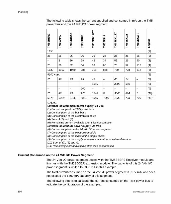
Planning
The following table shows the current supplied and consumed in mA on the TM5 power bus and the 24 Vdc I/O power segment:
Current Consumed on the 24 Vdc I/O Power Segment
The 24 Vdc I/O power segment begins with the TM5SBER2 Receiver module and finishes with the TM5SDO2R expansion module. The capacity of this 24 Vdc I/O power segment is limited to 6300 mA in this example.
The total current consumed on the 24 Vdc I/O power segment is 5577 mA, and does not exceed the 6300 mA capacity of this segment.
The following step is to calculate the current consumed on the TM5 power bus to validate the configuration of the example.
TM
5SB
ER
2
TM
5SA
I4L
TM
5SD
I12D
TM
5SD
I4D
TM
5SD
M12
DT
TM
5SD
I4A
TM
5SD
O12
T
TM
5SD
O2T
TM
5SD
O2R
Leg
end
1156 (1)
26 26 26 26 26 26 26 26 26 (2)
– 2 36 28 42 34 52 26 90 (3)
26 28 62 54 68 60 78 52 116 (4)
1130 1102 1040 986 918 858 780 728 612 (5)
6300 max. (6)
25 46 73 25 46 – 48 14 – (7)
– – – – 1500 – 3000 600 – (8)
– – – 200 – – – – – (9)
25 46 73 225 1546 0 3048 614 0 (10)
6275 6229 6156 5931 4385 4385 1337 723 723 (11)
Legend:External isolated main power supply, 24 Vdc (1) Current supplied on TM5 power bus(2) Consumption of the bus base(3) Consumption of the electronic module(4) Sum of (2) and (3)(5) Remaining current available after slice consumptionExternal isolated I/O power supply, 24 Vdc (6) Current supplied on the 24 Vdc I/O power segment(7) Consumption of the electronic module(8) Consumption of the loads of the output slices(9) Consumption of the supply to sensors, actuators or external devices(10) Sum of (7), (8) and (9)(11) Remaining current available after slice consumption
104 EIO0000000426 04/2012
Planning
Current Consumed on the TM5 Power Bus
The TM5SBER2 Receiver module generates 1156 mA on the TM5 power bus to supply remote expansion I/Os. The TM5 power bus begins with the TM5SBER2 remote expansion module and terminates with the TM5SDO2R remote expansion module.
The total current consumed on the TM5 power bus is 544 mA, and does not exceed the 1156 mA capacity of the TM5 power bus.
Final Configuration of the Example
This configuration does not need an additional PDM for power distribution.
Depending on the application, a PDM can be inserted to create separated groups (see page 87).
EIO0000000426 04/2012 105
Planning
4.4 Electrical Requirements
Introduction
The following section provides the general wiring rules and recommendations for the TM5 System. Considerations and techniques for grounding the TM5 System are also presented.
What’s in this Section?
This section contains the following topics:
Topic Page
Wiring Rules and Recommendations 107
Selecting an External 24 Vdc Power Supply 113
Wiring the Power Supply 114
Grounding the System 123
106 EIO0000000426 04/2012
Planning
Wiring Rules and Recommendations
Introduction
There are several rules that must be followed when wiring the TM5 System.
Wiring Rules
The following rules must be applied when wiring the TM5 System:I/O and communication wiring must be kept separate from the power wiring. Route these 2 types of wiring in separate cable ducting.Verify that the operating conditions and environment are within the specification values.Use proper wire sizes to meet voltage and current requirements.Use copper conductors only.Use twisted-pair, shielded cables for analog, expert or fast I/O and TM5 bus signals.Use twisted-pair, shielded cables for encoder, networks and field bus (CAN, serial, Ethernet).
DANGERHAZARD OF ELECTRIC SHOCK, EXPLOSION OR ARC FLASH
Disconnect all power from all equipment including connected devices prior to removing any covers or doors, or installing or removing any accessories, hardware, cables, or wires except under the specific conditions specified in the appropriate hardware guide for this equipment.Always use a properly rated voltage sensing device to confirm the power is off where and when indicated.Replace and secure all covers, accessories, hardware, cables, and wires and confirm that a proper ground connection exists before applying power to the unit.Use only the specified voltage when operating this equipment and any associated products.
Failure to follow these instructions will result in death or serious injury.
EIO0000000426 04/2012 107
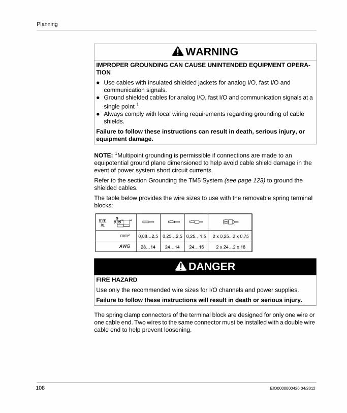
Planning
NOTE: 1Multipoint grounding is permissible if connections are made to an equipotential ground plane dimensioned to help avoid cable shield damage in the event of power system short circuit currents.
Refer to the section Grounding the TM5 System (see page 123) to ground the shielded cables.
The table below provides the wire sizes to use with the removable spring terminal blocks:
The spring clamp connectors of the terminal block are designed for only one wire or one cable end. Two wires to the same connector must be installed with a double wire cable end to help prevent loosening.
WARNINGIMPROPER GROUNDING CAN CAUSE UNINTENDED EQUIPMENT OPERA-TION
Use cables with insulated shielded jackets for analog I/O, fast I/O and communication signals.Ground shielded cables for analog I/O, fast I/O and communication signals at a
single point 1
Always comply with local wiring requirements regarding grounding of cable shields.
Failure to follow these instructions can result in death, serious injury, or equipment damage.
DANGERFIRE HAZARD
Use only the recommended wire sizes for I/O channels and power supplies.
Failure to follow these instructions will result in death or serious injury.
108 EIO0000000426 04/2012
Planning
Terminal Block
Plugging a terminal block into the incorrect electronic module can cause an electric shock or unintended operation of the application and/or damage the electronic module.
NOTE: To help prevent a terminal block from being inserted incorrectly, clearly and uniquely code and label each terminal block and electronic module according to the instructions in Coding the TM5 System (see page 160).
Stress Relief Using Cable Tie
There are two methods to reduce the stress on cables:The terminal blocks (see page 46) have slots to attach cable ties. A cable tie can be fed through this slot to secure cables and wires to reduce stress between them and the terminal block connections.After grounding the TM5 System via the TM2XMTGB grounding plate (see page 125), wires can be bundled and fixed to the grounding plate tabs using wire ties to reduce stress on the cables.
The table below provides the size of the cable tie and shows the two methods to reduce the stress on the cables:
DANGERLOOSE WIRING CAUSES ELECTRIC SHOCK
Do not insert more than one wire per connector of the terminal block without a double wire cable end.
Failure to follow these instructions will result in death or serious injury.
DANGERUNINTENDED EQUIPMENT OPERATION OR ELECTRIC SHOCK
Be sure to connect the terminal blocks to their designated location.
Failure to follow these instructions will result in death or serious injury.
Cable Tie Size Terminal block TM2XMTGB Grounding plate
Thickness 1.2 mm (0.05 in.) maximum 1.2 mm (0.05 in.)
Width 4 mm (0.16 in.) maximum 2.5...3 mm (0.1...0.12 in.)
EIO0000000426 04/2012 109
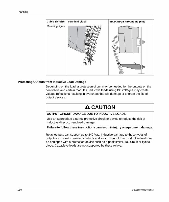
Planning
Protecting Outputs from Inductive Load Damage
Depending on the load, a protection circuit may be needed for the outputs on the controllers and certain modules. Inductive loads using DC voltages may create voltage reflections resulting in overshoot that will damage or shorten the life of output devices.
Relay outputs can support up to 240 Vac. Inductive damage to these types of outputs can result in welded contacts and loss of control. Each inductive load must be equipped with a protection device such as a peak limiter, RC circuit or flyback diode. Capacitive loads are not supported by these relays.
Mounting figure
Cable Tie Size Terminal block TM2XMTGB Grounding plate
CAUTIONOUTPUT CIRCUIT DAMAGE DUE TO INDUCTIVE LOADS
Use an appropriate external protective circuit or device to reduce the risk of inductive direct current load damage.
Failure to follow these instructions can result in injury or equipment damage.
110 EIO0000000426 04/2012
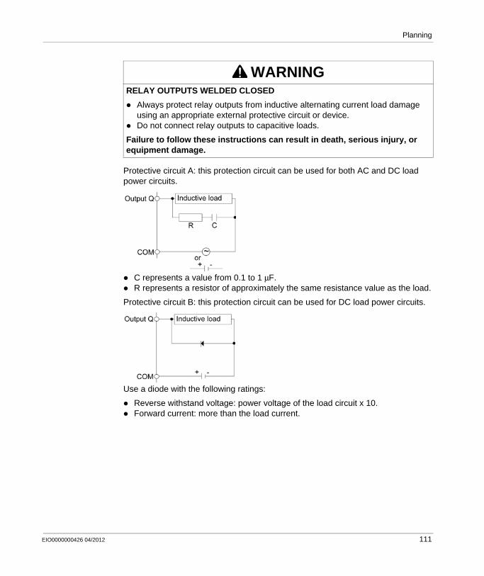
Planning
Protective circuit A: this protection circuit can be used for both AC and DC load power circuits.
C represents a value from 0.1 to 1 μF.R represents a resistor of approximately the same resistance value as the load.
Protective circuit B: this protection circuit can be used for DC load power circuits.
Use a diode with the following ratings:
Reverse withstand voltage: power voltage of the load circuit x 10.Forward current: more than the load current.
WARNINGRELAY OUTPUTS WELDED CLOSED
Always protect relay outputs from inductive alternating current load damage using an appropriate external protective circuit or device.Do not connect relay outputs to capacitive loads.
Failure to follow these instructions can result in death, serious injury, or equipment damage.
EIO0000000426 04/2012 111
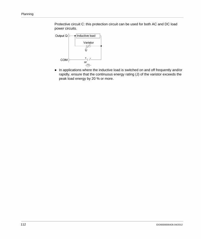
Planning
Protective circuit C: this protection circuit can be used for both AC and DC load power circuits.
In applications where the inductive load is switched on and off frequently and/or rapidly, ensure that the continuous energy rating (J) of the varistor exceeds the peak load energy by 20 % or more.
112 EIO0000000426 04/2012
Planning
Selecting an External 24 Vdc Power Supply
Characteristics of the 24 Vdc Power Supply
The TM5 System requires power supplies with a nominal voltage of 24 Vdc. The 24 Vdc power supplies must be rated Safety Extra Low Voltage (SELV) or Protective Extra Low Voltage (PELV) according to IEC 61140. These power supplies are isolated between the electrical input and output circuits of the power supply.
Calculating the Power Supply Requirement
Refer to Power Distribution System Design (see page 94).
WARNINGPOTENTIAL OF OVERHEATING AND FIRE
Do not connect the modules directly to line voltage.Use only isolating PELV or SELV power supplies to supply power to the modules.
Failure to follow these instructions can result in death, serious injury, or equipment damage.
EIO0000000426 04/2012 113
Planning
Wiring the Power Supply
Overview
To distribute current for the 24 Vdc I/O power segment(s) and TM5 power bus according to the power distribution description (see page 85), the following modules are connected to an external source:
Controller Power Distribution Module (CPDM)Interface Power Distribution Module (IPDM)Receiver module (TM5SBER2)Power Distribution Module (PDM) TM5SPS1• Power Distribution Module (PDM) TM5SPS2•
Source power for these can come from one or more supplies. Your requirements are dictated by:
voltage and current needsisolation requirements
Wiring the Controller Power Distribution Module (CPDM)
The CPDM (see page 89) is the connection of the controller to the external 24 Vdc power supplies and the beginning of the power distribution for the local configuration. Power can be supplied by two or three external isolated power supplies depending on current needs and capabilities.
There are three power connections to be made to the CPDM from your source power supplies:
WARNINGPOTENTIAL OF OVERHEATING AND FIRE
Do not connect the modules directly to line voltage.Use only isolating PELV or SELV power supplies to supply power to the modules.
Failure to follow these instructions can result in death, serious injury, or equipment damage.
Connections 2 Power Supplies 3 Power Supplies
24 Vdc embedded expert modules power PS1 PS0
24 Vdc Main power that generates power for TM5 power bus
PS1
24 Vdc I/O power segment PS2 PS2
114 EIO0000000426 04/2012
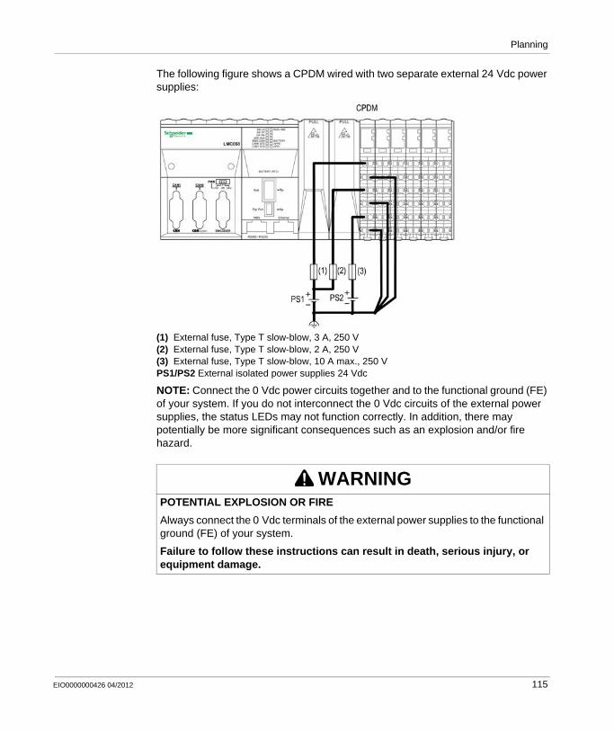
Planning
The following figure shows a CPDM wired with two separate external 24 Vdc power supplies:
(1) External fuse, Type T slow-blow, 3 A, 250 V(2) External fuse, Type T slow-blow, 2 A, 250 V(3) External fuse, Type T slow-blow, 10 A max., 250 VPS1/PS2 External isolated power supplies 24 Vdc
NOTE: Connect the 0 Vdc power circuits together and to the functional ground (FE) of your system. If you do not interconnect the 0 Vdc circuits of the external power supplies, the status LEDs may not function correctly. In addition, there may potentially be more significant consequences such as an explosion and/or fire hazard.
WARNINGPOTENTIAL EXPLOSION OR FIRE
Always connect the 0 Vdc terminals of the external power supplies to the functional ground (FE) of your system.
Failure to follow these instructions can result in death, serious injury, or equipment damage.
EIO0000000426 04/2012 115

Planning
The following figure shows the wiring of the CPDM with three separate external 24 Vdc power supplies:
(1) External fuse, Type T slow-blow, 3 A, 250 V(2) External fuse, Type T slow-blow, 2 A, 250 V(3) External fuse, Type T slow-blow, 10 A max., 250 VPS0/PS1/PS2 External isolated power supply 24 Vdc
NOTE: Connect the 0 Vdc power circuits together and to the functional ground (FE) of your system. If you do not interconnect the 0 Vdc circuits of the external power supplies, the status LEDs may not function correctly. In addition, there may potentially be more significant consequences such as an explosion and/or fire hazard.
Wiring the Interface Power Distribution Module (TM5SPS3)
The IPDM (TM5SPS3) (see page 90) is the first connection of the distributed configuration to the external 24 Vdc power supplies. Power is supplied by two external isolated power supplies.
WARNINGPOTENTIAL EXPLOSION OR FIRE
Always connect the 0 Vdc terminals of the external power supplies to the functional ground (FE) of your system.
Failure to follow these instructions can result in death, serious injury, or equipment damage.
116 EIO0000000426 04/2012

Planning
There are two power connections to be made to the IPDM (IPDM TM5SPS3) from your source power supplies:
(2) External fuse, Type T slow-blow, 1 A, 250 V(3) External fuse, Type T slow-blow, 10 A max., 250 VPS1/PS2 External isolated power supply 24 Vdc
NOTE: Connect the 0 Vdc power circuits together and to the functional ground (FE) of your system. If you do not interconnect the 0 Vdc circuits of the external power supplies, the status LEDs may not function correctly. In addition, there may potentially be more significant consequences such as an explosion and/or fire hazard.
Connections 2 Power Supplies
24 Vdc Main power that generates power for TM5 power bus
PS1
24 Vdc I/O power segment PS2
WARNINGPOTENTIAL EXPLOSION OR FIRE
Always connect the 0 Vdc terminals of the external power supplies to the functional ground (FE) of your system.
Failure to follow these instructions can result in death, serious injury, or equipment damage.
EIO0000000426 04/2012 117
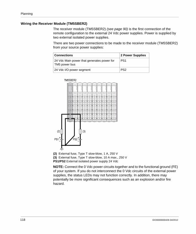
Planning
Wiring the Receiver Module (TM5SBER2)
The receiver module (TM5SBER2) (see page 90) is the first connection of the remote configuration to the external 24 Vdc power supplies. Power is supplied by two external isolated power supplies.
There are two power connections to be made to the receiver module (TM5SBER2) from your source power supplies:
(2) External fuse, Type T slow-blow, 1 A, 250 V(3) External fuse, Type T slow-blow, 10 A max., 250 VPS1/PS2 External isolated power supply 24 Vdc
NOTE: Connect the 0 Vdc power circuits together and to the functional ground (FE) of your system. If you do not interconnect the 0 Vdc circuits of the external power supplies, the status LEDs may not function correctly. In addition, there may potentially be more significant consequences such as an explosion and/or fire hazard.
Connections 2 Power Supplies
24 Vdc Main power that generates power for TM5 power bus
PS1
24 Vdc I/O power segment PS2
118 EIO0000000426 04/2012
Planning
Wiring the Power Distribution Module TM5SPS1•
The TM5SPS1• (PDM) divides the 24 Vdc I/O power segment into several separated 24 Vdc I/O power segments (see page 87). Each separated 24 Vdc I/O power segment is supplied by one external isolated power supply depending on current needs and capabilities.
There is one power connection to be made to each TM5SPS1• (PDM) from your source power supplies:
WARNINGPOTENTIAL EXPLOSION OR FIRE
Always connect the 0 Vdc terminals of the external power supplies to the functional ground (FE) of your system.
Failure to follow these instructions can result in death, serious injury, or equipment damage.
Segment Begin Connection Power Supplies
CPDM for local configuration or the receiver module for remote configuration or the IPDM for distributed configuration
24 Vdc I/O power segment 1 PS2
First PDM (from left to right) of the configuration
24 Vdc I/O power segment 2 PS3
Second PDM (from left to right) of the configuration
24 Vdc I/O power segment 3 PS4
... ... ...
EIO0000000426 04/2012 119
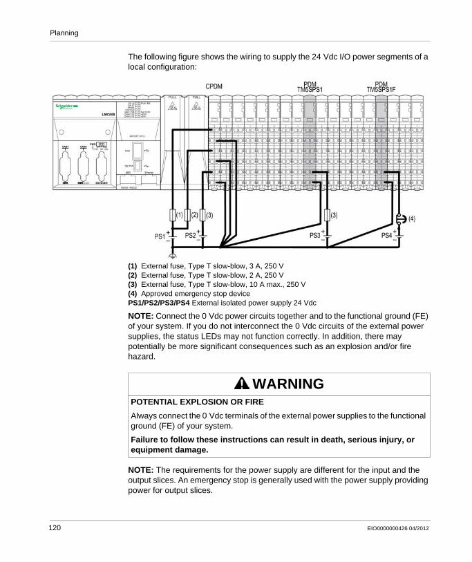
Planning
The following figure shows the wiring to supply the 24 Vdc I/O power segments of a local configuration:
(1) External fuse, Type T slow-blow, 3 A, 250 V(2) External fuse, Type T slow-blow, 2 A, 250 V(3) External fuse, Type T slow-blow, 10 A max., 250 V(4) Approved emergency stop devicePS1/PS2/PS3/PS4 External isolated power supply 24 Vdc
NOTE: Connect the 0 Vdc power circuits together and to the functional ground (FE) of your system. If you do not interconnect the 0 Vdc circuits of the external power supplies, the status LEDs may not function correctly. In addition, there may potentially be more significant consequences such as an explosion and/or fire hazard.
NOTE: The requirements for the power supply are different for the input and the output slices. An emergency stop is generally used with the power supply providing power for output slices.
WARNINGPOTENTIAL EXPLOSION OR FIRE
Always connect the 0 Vdc terminals of the external power supplies to the functional ground (FE) of your system.
Failure to follow these instructions can result in death, serious injury, or equipment damage.
120 EIO0000000426 04/2012
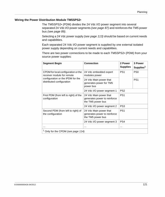
Planning
Wiring the Power Distribution Module TM5SPS2•
The TM5SPS2• (PDM) divides the 24 Vdc I/O power segment into several separated 24 Vdc I/O power segments (see page 87) and reinforces the TM5 power bus (see page 89).
Selecting a 24 Vdc power supply (see page 113) should be based on current needs and capabilities.
Each separated 24 Vdc I/O power segment is supplied by one external isolated power supply depending on current needs and capabilities.
There are two power connections to be made to each TM5SPS2• (PDM) from your source power supplies:
Segment Begin Connection 2 Power Supplies
3 Power
Supplies1
CPDM for local configuration or the receiver module for remote configuration or the IPDM for the distributed configuration
24 Vdc embedded expert modules power
PS1 PS0
24 Vdc Main power that generates power for TM5 power bus
PS1
24 Vdc I/O power segment 1 PS2
First PDM (from left to right) of the configuration
24 Vdc Main power that generates power to reinforce the TM5 power bus
PS1
24 Vdc I/O power segment 2 PS3
Second PDM (from left to right) of the configuration
24 Vdc Main power that generates power to reinforce the TM5 power bus
PS1
24 Vdc I/O power segment 3 PS4
... ... ...
1 Only for the CPDM (see page 114).
EIO0000000426 04/2012 121
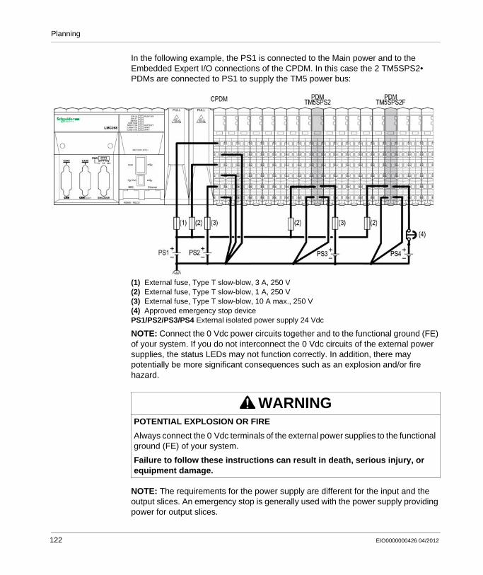
Planning
In the following example, the PS1 is connected to the Main power and to the Embedded Expert I/O connections of the CPDM. In this case the 2 TM5SPS2• PDMs are connected to PS1 to supply the TM5 power bus:
(1) External fuse, Type T slow-blow, 3 A, 250 V(2) External fuse, Type T slow-blow, 1 A, 250 V(3) External fuse, Type T slow-blow, 10 A max., 250 V(4) Approved emergency stop devicePS1/PS2/PS3/PS4 External isolated power supply 24 Vdc
NOTE: Connect the 0 Vdc power circuits together and to the functional ground (FE) of your system. If you do not interconnect the 0 Vdc circuits of the external power supplies, the status LEDs may not function correctly. In addition, there may potentially be more significant consequences such as an explosion and/or fire hazard.
NOTE: The requirements for the power supply are different for the input and the output slices. An emergency stop is generally used with the power supply providing power for output slices.
WARNINGPOTENTIAL EXPLOSION OR FIRE
Always connect the 0 Vdc terminals of the external power supplies to the functional ground (FE) of your system.
Failure to follow these instructions can result in death, serious injury, or equipment damage.
122 EIO0000000426 04/2012
Planning
Grounding the System
Introduction
To help minimize the effects of electromagnetic interference, cables carrying the fast I/O, analog I/O, network and field bus communication signals must be shielded.
NOTE: 1Multipoint grounding is permissible if connections are made to an equipotential ground plane dimensioned to help avoid cable shield damage in the event of power system short circuit currents.
The use of shielded cables requires compliance with the following wiring rules:For protective ground connections (PE), metal conduit or ducting can be used for part of the shielding length, provided there is no break in the continuity of the ground connections. For functional ground (FE), the shielding is intended to attenuate electromagnetic interference and the shielding must be continuous for the length of the cable. If the purpose is both functional and protective, as is often the case for communication cables, the cable should have continuous shielding.Wherever possible, keep cables carrying one type of signal separate from the cables carrying other types of signals or power.
WARNINGIMPROPER GROUNDING CAN CAUSE UNINTENDED EQUIPMENT OPERA-TION
Use cables with insulated shielded jackets for analog I/O, fast I/O and communication signals.Ground shielded cables for analog I/O, fast I/O and communication signals at a
single point 1
Always comply with local wiring requirements regarding grounding of cable shields.
Failure to follow these instructions can result in death, serious injury, or equipment damage.
EIO0000000426 04/2012 123
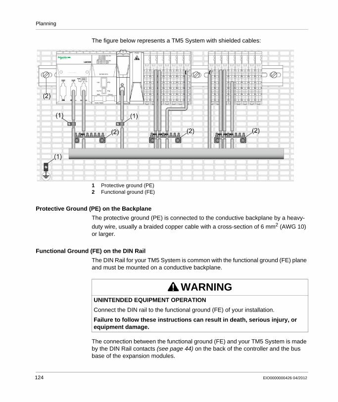
Planning
The figure below represents a TM5 System with shielded cables:
1 Protective ground (PE)2 Functional ground (FE)
Protective Ground (PE) on the Backplane
The protective ground (PE) is connected to the conductive backplane by a heavy-
duty wire, usually a braided copper cable with a cross-section of 6 mm2 (AWG 10) or larger.
Functional Ground (FE) on the DIN Rail
The DIN Rail for your TM5 System is common with the functional ground (FE) plane and must be mounted on a conductive backplane.
The connection between the functional ground (FE) and your TM5 System is made by the DIN Rail contacts (see page 44) on the back of the controller and the bus base of the expansion modules.
WARNINGUNINTENDED EQUIPMENT OPERATION
Connect the DIN rail to the functional ground (FE) of your installation.
Failure to follow these instructions can result in death, serious injury, or equipment damage.
124 EIO0000000426 04/2012
Planning
Shielded Cables Connections
Cables carrying the fast I/O, analog I/O, network and field bus communication signals must be shielded. The shielding must be securely connected to ground. The fast I/O and analog I/O shields may be connected either to the functional ground (FE) of your system via the TM2XMTGB grounding bar or to the protective ground (PE). The field bus communication cable shields must be connected to the protective ground (PE) with a connecting clamp secured to the conductive backplane of your installation.
The shielding of the following cables must be connected to the protective ground (PE):
CANopenModbus
NOTE: The functional ground of the Ethernet connection is internal.
WARNINGACCIDENTAL DISCONNECTION FROM PROTECTIVE GROUND (PE)
Do not use the TM2XMTGB Grounding Bar to provide a protective ground (PE).Use the TM2XMTGB Grounding Bar only to provide a functional ground (FE).
Failure to follow these instructions can result in death, serious injury, or equipment damage.
DANGERHAZARD OF ELECTRIC SHOCK
Make sure that CANopen and Modbus cables are securely connected to the protective ground (PE).
Failure to follow these instructions will result in death or serious injury.
EIO0000000426 04/2012 125
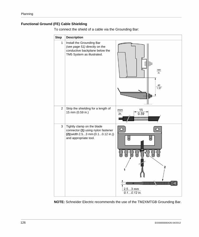
Planning
Functional Ground (FE) Cable Shielding
To connect the shield of a cable via the Grounding Bar:
NOTE: Schneider Electric recommends the use of the TM2XMTGB Grounding Bar.
Step Description
1 Install the Grounding Bar (see page 51) directly on the conductive backplane below the TM5 System as illustrated.
2 Strip the shielding for a length of 15 mm (0.59 in.)
3 Tightly clamp on the blade connector (1) using nylon fastener (2)(width 2.5...3 mm (0.1...0.12 in.)) and appropriate tool.
126 EIO0000000426 04/2012
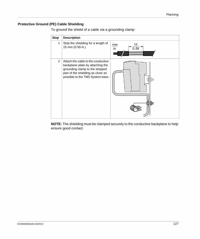
Planning
Protective Ground (PE) Cable Shielding
To ground the shield of a cable via a grounding clamp:
NOTE: The shielding must be clamped securely to the conductive backplane to help ensure good contact.
Step Description
1 Strip the shielding for a length of 15 mm (0.59 in.)
2 Attach the cable to the conductive backplane plate by attaching the grounding clamp to the stripped part of the shielding as close as possible to the TM5 System base.
EIO0000000426 04/2012 127

Planning
128 EIO0000000426 04/2012
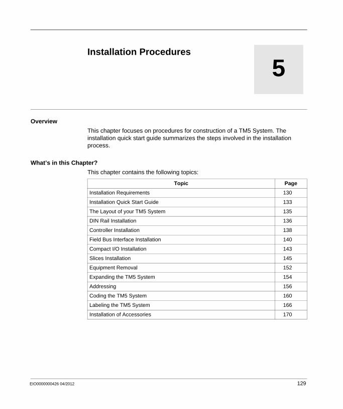
EIO0000000426 04/2012
5
Modicon TM5 / TM7 Flexible System
Installation Procedures
EIO0000000426 04/2012
Installation Procedures
Overview
This chapter focuses on procedures for construction of a TM5 System. The installation quick start guide summarizes the steps involved in the installation process.
What’s in this Chapter?
This chapter contains the following topics:
Topic Page
Installation Requirements 130
Installation Quick Start Guide 133
The Layout of your TM5 System 135
DIN Rail Installation 136
Controller Installation 138
Field Bus Interface Installation 140
Compact I/O Installation 143
Slices Installation 145
Equipment Removal 152
Expanding the TM5 System 154
Addressing 156
Coding the TM5 System 160
Labeling the TM5 System 166
Installation of Accessories 170
129
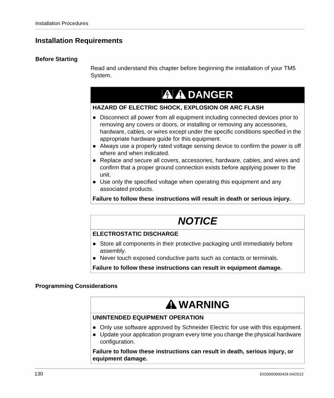
Installation Procedures
Installation Requirements
Before Starting
Read and understand this chapter before beginning the installation of your TM5 System.
Programming Considerations
DANGERHAZARD OF ELECTRIC SHOCK, EXPLOSION OR ARC FLASH
Disconnect all power from all equipment including connected devices prior to removing any covers or doors, or installing or removing any accessories, hardware, cables, or wires except under the specific conditions specified in the appropriate hardware guide for this equipment.Always use a properly rated voltage sensing device to confirm the power is off where and when indicated.Replace and secure all covers, accessories, hardware, cables, and wires and confirm that a proper ground connection exists before applying power to the unit.Use only the specified voltage when operating this equipment and any associated products.
Failure to follow these instructions will result in death or serious injury.
NOTICEELECTROSTATIC DISCHARGE
Store all components in their protective packaging until immediately before assembly.Never touch exposed conductive parts such as contacts or terminals.
Failure to follow these instructions can result in equipment damage.
WARNINGUNINTENDED EQUIPMENT OPERATION
Only use software approved by Schneider Electric for use with this equipment.Update your application program every time you change the physical hardware configuration.
Failure to follow these instructions can result in death, serious injury, or equipment damage.
130 EIO0000000426 04/2012

Installation Procedures
Operating Environment
DANGEREXPLOSIVE POTENTIAL
Only use this equipment in non-hazardous locations, or in locations that comply with Class I, Division 2, Groups A, B, C and D.Do not substitute components which would impair compliance to Class I Division 2.Do not connect or disconnect equipment unless power has been removed or the location is known to be non-hazardous.
Failure to follow these instructions will result in death or serious injury.
WARNINGUNINTENDED EQUIPMENT OPERATION
Install and operate this equipment according to the environmental conditions described in the operating limits.
Failure to follow these instructions can result in death, serious injury, or equipment damage.
EIO0000000426 04/2012 131

Installation Procedures
Installation Considerations
NOTE: Schneider Electric recommends the use of UL-recognized and CSA approved JDYX2 or JDYX8 fuse types.
WARNINGUNINTENDED EQUIPMENT OPERATION
Use appropriate safety interlocks where personnel and/or equipment hazards exist.Install and operate this equipment in an enclosure appropriately rated for its intended environment.Use the sensor and actuator power supplies only for supplying power to the sensors or actuators connected to the module.Power line and output circuits must be wired and fused in compliance with local and national regulatory requirements for the rated current and voltage of the particular equipment.Do not use this equipment in safety-critical machine functions.Do not disassemble, repair, or modify this equipment.Do not connect any wiring to reserved, unused connections, or to connections designated as Not Connected (N.C.).
Failure to follow these instructions can result in death, serious injury, or equipment damage.
132 EIO0000000426 04/2012
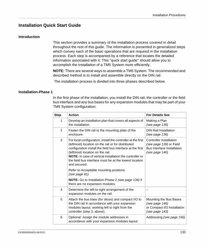
Installation Procedures
Installation Quick Start Guide
Introduction
This section provides a summary of the installation process covered in detail throughout the rest of this guide. The information is presented in generalized steps which convey each of the basic operations that are required in the installation process. Each step is accompanied by a reference that locates the detailed information associated with it. This "quick start guide" should allow you to accomplish the installation of a TM5 System more efficiently.
NOTE: There are several ways to assemble a TM5 System. The recommended and described method is to install and assemble directly on the DIN rail.
The installation process is divided into three phases described below.
Installation-Phase 1
In the first phase of the installation, you install the DIN rail, the controller or the field bus interface and any bus bases for any expansion modules that may be part of your TM5 System configuration:
Step Action For Details See
1 Develop an installation plan that covers all aspects of the installation.
Making a Plan (see page 135)
2 Fasten the DIN rail to the mounting plate of the enclosure.
DIN Rail Installation (see page 136)
3 For local configuration, install the controller at the first (leftmost) location on the rail or for distributed configuration install the field bus interface at the first (leftmost) location on the rail.NOTE: In case of vertical installation the controller or the field bus interface must be at the lowest location and secured.
Refer to Acceptable mounting positions (see page 81).
NOTE: Go to Installation-Phase 2 (see page 134) if there are no expansion modules.
Controller Installation (see page 139) or Field Bus Interface Installation (see page 140)
4 Determine the left-to-right arrangement of the expansion modules on the rail.
–
5 Attach the bus base (for slices) and compact I/O to the DIN rail in accordance with your expansion modules layout, working left to right from the controller (step 3, above).
Mounting the Bus Bases (see page 146)or Compact I/O Installation (see page 143)
6 Optional: Assign the module addresses in accordance with your expansion modules layout.
Addressing (see page 156)
EIO0000000426 04/2012 133
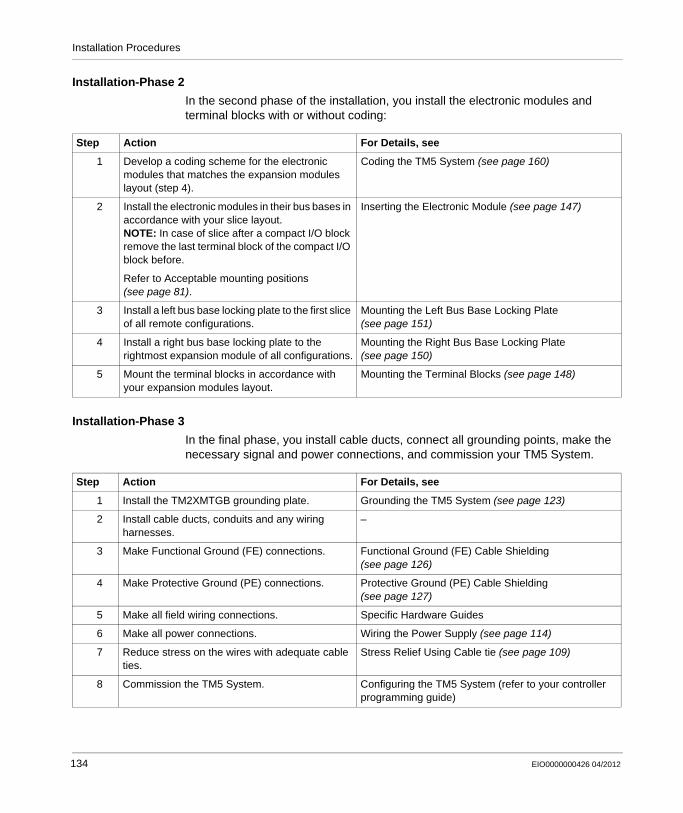
Installation Procedures
Installation-Phase 2
In the second phase of the installation, you install the electronic modules and terminal blocks with or without coding:
Installation-Phase 3
In the final phase, you install cable ducts, connect all grounding points, make the necessary signal and power connections, and commission your TM5 System.
Step Action For Details, see
1 Develop a coding scheme for the electronic modules that matches the expansion modules layout (step 4).
Coding the TM5 System (see page 160)
2 Install the electronic modules in their bus bases in accordance with your slice layout.NOTE: In case of slice after a compact I/O block remove the last terminal block of the compact I/O block before.
Refer to Acceptable mounting positions (see page 81).
Inserting the Electronic Module (see page 147)
3 Install a left bus base locking plate to the first slice of all remote configurations.
Mounting the Left Bus Base Locking Plate (see page 151)
4 Install a right bus base locking plate to the rightmost expansion module of all configurations.
Mounting the Right Bus Base Locking Plate (see page 150)
5 Mount the terminal blocks in accordance with your expansion modules layout.
Mounting the Terminal Blocks (see page 148)
Step Action For Details, see
1 Install the TM2XMTGB grounding plate. Grounding the TM5 System (see page 123)
2 Install cable ducts, conduits and any wiring harnesses.
–
3 Make Functional Ground (FE) connections. Functional Ground (FE) Cable Shielding (see page 126)
4 Make Protective Ground (PE) connections. Protective Ground (PE) Cable Shielding (see page 127)
5 Make all field wiring connections. Specific Hardware Guides
6 Make all power connections. Wiring the Power Supply (see page 114)
7 Reduce stress on the wires with adequate cable ties.
Stress Relief Using Cable tie (see page 109)
8 Commission the TM5 System. Configuring the TM5 System (refer to your controller programming guide)
134 EIO0000000426 04/2012
Installation Procedures
The Layout of your TM5 System
Making a Plan
Before you begin to install your TM5 System, you need to establish a plan that identifies:
the type of enclosure for the TM5 Systemthe number and type of expansion modules on your TM5 Systemthe order in which any TM5 expansion modules are assembled together to form the TM5 busthe power requirements of your TM5 System configurationa coding scheme that helps match the correct terminal blocks with their electronic modulesa labeling plan
Establishing and following a clear plan is invaluable. The local TM5 bus is constructed as a series of interconnected bus base units. The structure of the TM5 backplane is defined by the type and order of electronic modules that will reside in it. You will need to make these decisions in advance and the association table (see page 242) can help you. There is a color coding system (see page 24) in the TM5 System. In addition, there is a coding system for optional coding (see page 160) of the electronic modules and terminal blocks that is recommended. Careful labeling (see page 166) of your TM5 System is also recommended.
Selecting Expansion Modules
When you plan a TM5 System layout, some important things you need to know are the number and type of expansion electronic modules and their matching bus bases and terminal blocks.
NOTE: There are restrictions and regulations associated with certain module types. Please refer to the TM5 expansion I/O hardware guides for more information
Once the number and type of modules has been established, it becomes possible to determine power distribution requirements (see page 94), your external power source requirements (see page 113) and the overall hardware design.
EIO0000000426 04/2012 135
Installation Procedures
DIN Rail Installation
Grounding Function
The DIN rail must be attached to a conductive backplane that itself is connected to a protective ground (PE) (see page 124).
In the mounting channel of each piece of the TM5 equipment is a metal spring contact. When properly mounted on a metal DIN rail, these contacts provide connection to the functional ground (FE) (see page 124) for the entire TM5 System.
Mounting the DIN Rail
The TM5 System components are designed for mounting on rail conforming to IEC 60715.
To help achieve the stated TM5 System performance characteristics, the mounting hardware must be installed at the end positions and at 100 mm (3.94 in.) maximum increments along the length of the rail.
WARNINGUNINTENDED EQUIPMENT OPERATION
Verify that the DIN rail is securely installed with mounting hardware at the end positions and at 100 mm (3.94 in.) maximum increments along the length of the rail.Be sure that the DIN rail is firmly connected to a conductive backplane, and that the conductive backplane is secured to a protective ground as specified in this guide and in accordance with local regulations.
Failure to follow these instructions can result in death, serious injury, or equipment damage.
136 EIO0000000426 04/2012
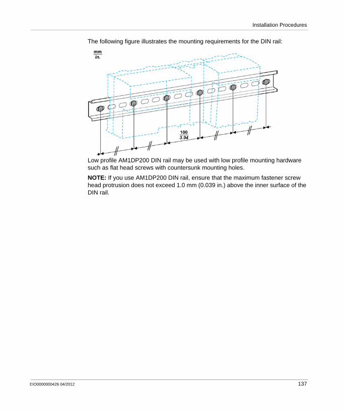
Installation Procedures
The following figure illustrates the mounting requirements for the DIN rail:
Low profile AM1DP200 DIN rail may be used with low profile mounting hardware such as flat head screws with countersunk mounting holes.
NOTE: If you use AM1DP200 DIN rail, ensure that the maximum fastener screw head protrusion does not exceed 1.0 mm (0.039 in.) above the inner surface of the DIN rail.
EIO0000000426 04/2012 137
Installation Procedures
Controller Installation
Introduction
The following procedure describes how to mount a controller on the DIN rail.
NOTE: If the controller is already installed and wired, or the slice connectors are prewired, be sure to remove all power before attempting these procedures.
DANGERHAZARD OF ELECTRIC SHOCK, EXPLOSION OR ARC FLASH
Disconnect all power from all equipment including connected devices prior to removing any covers or doors, or installing or removing any accessories, hardware, cables, or wires except under the specific conditions specified in the appropriate hardware guide for this equipment.Always use a properly rated voltage sensing device to confirm the power is off where and when indicated.Replace and secure all covers, accessories, hardware, cables, and wires and confirm that a proper ground connection exists before applying power to the unit.Use only the specified voltage when operating this equipment and any associated products.
Failure to follow these instructions will result in death or serious injury.
138 EIO0000000426 04/2012
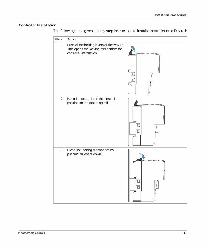
Installation Procedures
Controller Installation
The following table gives step by step instructions to install a controller on a DIN rail:
Step Action
1 Push all the locking levers all the way up. This opens the locking mechanism for controller installation.
2 Hang the controller in the desired position on the mounting rail.
3 Close the locking mechanism by pushing all levers down.
EIO0000000426 04/2012 139
Installation Procedures
Field Bus Interface Installation
Introduction
The installation procedure of the field bus interface is to assemble the 4 components and then install it directly on the DIN rail.
NOTE: If the field bus interface is already installed and wired, or the connectors are pre-wired, be sure to remove all power before attempting these procedures.
DANGERHAZARD OF ELECTRIC SHOCK, EXPLOSION OR ARC FLASH
Disconnect all power from all equipment including connected devices prior to removing any covers or doors, or installing or removing any accessories, hardware, cables, or wires except under the specific conditions specified in the appropriate hardware guide for this equipment.Always use a properly rated voltage sensing device to confirm the power is off where and when indicated.Replace and secure all covers, accessories, hardware, cables, and wires and confirm that a proper ground connection exists before applying power to the unit.Use only the specified voltage when operating this equipment and any associated products.
Failure to follow these instructions will result in death or serious injury.
NOTICEELECTROSTATIC DISCHARGE
Store electronic components in their protective packaging until immediately before assembly.Only touch modules on the housing.Take the necessary protective measures against electrostatic discharges.
Failure to follow these instructions can result in equipment damage.
140 EIO0000000426 04/2012
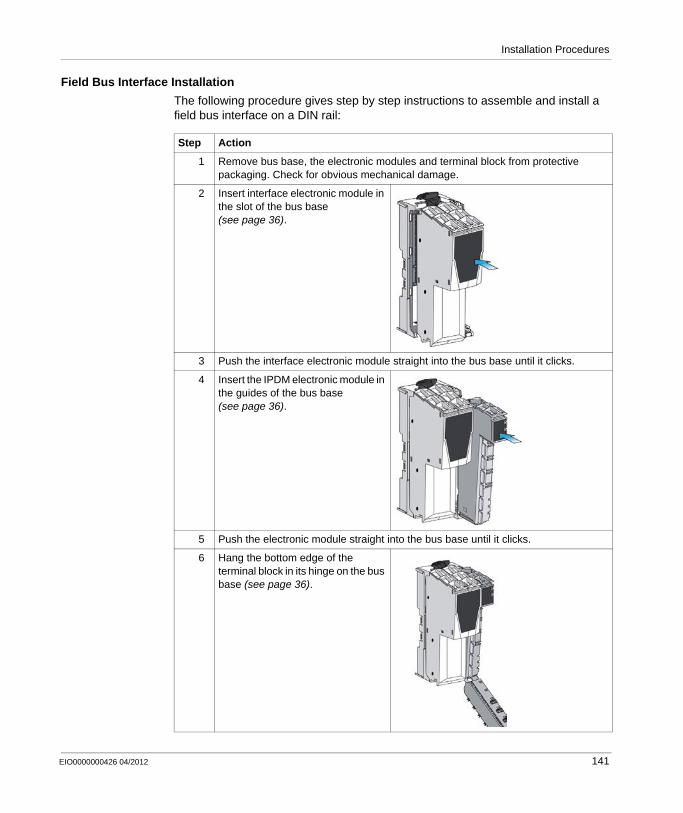
Installation Procedures
Field Bus Interface Installation
The following procedure gives step by step instructions to assemble and install a field bus interface on a DIN rail:
Step Action
1 Remove bus base, the electronic modules and terminal block from protective packaging. Check for obvious mechanical damage.
2 Insert interface electronic module in the slot of the bus base (see page 36).
3 Push the interface electronic module straight into the bus base until it clicks.
4 Insert the IPDM electronic module in the guides of the bus base (see page 36).
5 Push the electronic module straight into the bus base until it clicks.
6 Hang the bottom edge of the terminal block in its hinge on the bus base (see page 36).
EIO0000000426 04/2012 141
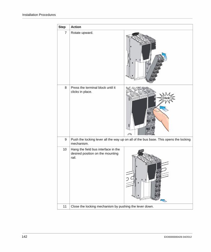
Installation Procedures
7 Rotate upward.
8 Press the terminal block until it clicks in place.
9 Push the locking lever all the way up on all of the bus base. This opens the locking mechanism.
10 Hang the field bus interface in the desired position on the mounting rail.
11 Close the locking mechanism by pushing the lever down.
Step Action
142 EIO0000000426 04/2012
Installation Procedures
Compact I/O Installation
Introduction
The compact I/O is always preceded by a controller or a slice. The installation procedure of the compact I/O is to install it directly on the DIN rail.
NOTE: If the controller is already installed and wired, or the slice connectors are pre-wired, be sure to remove all power before attempting these procedures.
DANGERHAZARD OF ELECTRIC SHOCK, EXPLOSION OR ARC FLASH
Disconnect all power from all equipment including connected devices prior to removing any covers or doors, or installing or removing any accessories, hardware, cables, or wires except under the specific conditions specified in the appropriate hardware guide for this equipment.Always use a properly rated voltage sensing device to confirm the power is off where and when indicated.Replace and secure all covers, accessories, hardware, cables, and wires and confirm that a proper ground connection exists before applying power to the unit.Use only the specified voltage when operating this equipment and any associated products.
Failure to follow these instructions will result in death or serious injury.
NOTICEELECTROSTATIC DISCHARGE
Store electronic components in their protective packaging until immediately before assembly.Only touch modules on the housing.Take the necessary protective measures against electrostatic discharges.
Failure to follow these instructions can result in equipment damage.
EIO0000000426 04/2012 143
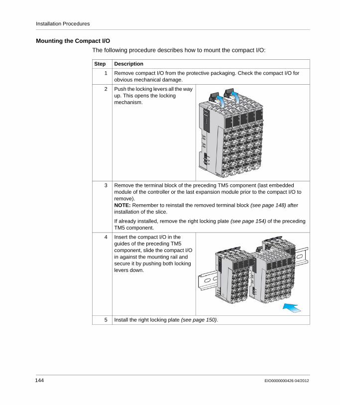
Installation Procedures
Mounting the Compact I/O
The following procedure describes how to mount the compact I/O:
Step Description
1 Remove compact I/O from the protective packaging. Check the compact I/O for obvious mechanical damage.
2 Push the locking levers all the way up. This opens the locking mechanism.
3 Remove the terminal block of the preceding TM5 component (last embedded module of the controller or the last expansion module prior to the compact I/O to remove).NOTE: Remember to reinstall the removed terminal block (see page 148) after installation of the slice.
If already installed, remove the right locking plate (see page 154) of the preceding TM5 component.
4 Insert the compact I/O in the guides of the preceding TM5 component, slide the compact I/O in against the mounting rail and secure it by pushing both locking levers down.
5 Install the right locking plate (see page 150).
144 EIO0000000426 04/2012

Installation Procedures
Slices Installation
Introduction
The installation procedure of the slices is to install and assemble them directly on the DIN rail:1 Mount the bus bases.2 Insert the electronic modules.3 Mount the terminal blocks.
NOTE: If the controller is already installed and wired, or the slice connectors are pre-wired, be sure to remove all power before attempting these procedures.
The installation procedure for the first bus base depends whether it is a local, remote or distributed configuration.
DANGERHAZARD OF ELECTRIC SHOCK, EXPLOSION OR ARC FLASH
Disconnect all power from all equipment including connected devices prior to removing any covers or doors, or installing or removing any accessories, hardware, cables, or wires except under the specific conditions specified in the appropriate hardware guide for this equipment.Always use a properly rated voltage sensing device to confirm the power is off where and when indicated.Replace and secure all covers, accessories, hardware, cables, and wires and confirm that a proper ground connection exists before applying power to the unit.Use only the specified voltage when operating this equipment and any associated products.
Failure to follow these instructions will result in death or serious injury.
NOTICEELECTROSTATIC DISCHARGE
Store electronic components in their protective packaging until immediately before assembly.Only touch modules on the housing.Take the necessary protective measures against electrostatic discharges.
Failure to follow these instructions can result in equipment damage.
EIO0000000426 04/2012 145

Installation Procedures
Mounting the Bus Bases
The following procedure describes how to mount the bus bases:
NOTE: Remember to reinstall the removed terminal block (see page 148) after installation of the slice.
Step Description
1 Remove bus bases from protective packaging. Check the bus bases for obvious mechanical damage.
2 Push the locking lever all the way up on all of the bus bases. This opens the locking mechanism.
3 Local configuration: Remove the terminal block of the last embedded module of the controller.
Remote configuration: Go to next step.Distributed configuration: Remove the terminal block of the IPDM of the field bus
interface.
4 Local configuration: Insert the first bus base in the guides of the controller, slide the bus base in against the mounting rail and secure it by pushing the lever down.
Remote configuration: Hang the first bus base in the desired position on the mounting rail and close the locking mechanism by pushing the lever down.
Distributed configuration: Insert the first bus base in the guides of the field bus interface bus base, slide the bus base in against the mounting rail and secure it by pushing the lever down.
5 Insert the next bus base in the guides of the previously mounted bus base.
6 Slide the bus base in against the mounting rail and secure it by pushing down the locking lever.
7 According to the installation plan, proceed like this with the rest of the bus bases.
8 If using bus bases with address setting, assign the bus base address (see page 156) at this step of the installation procedure of the slices.
146 EIO0000000426 04/2012
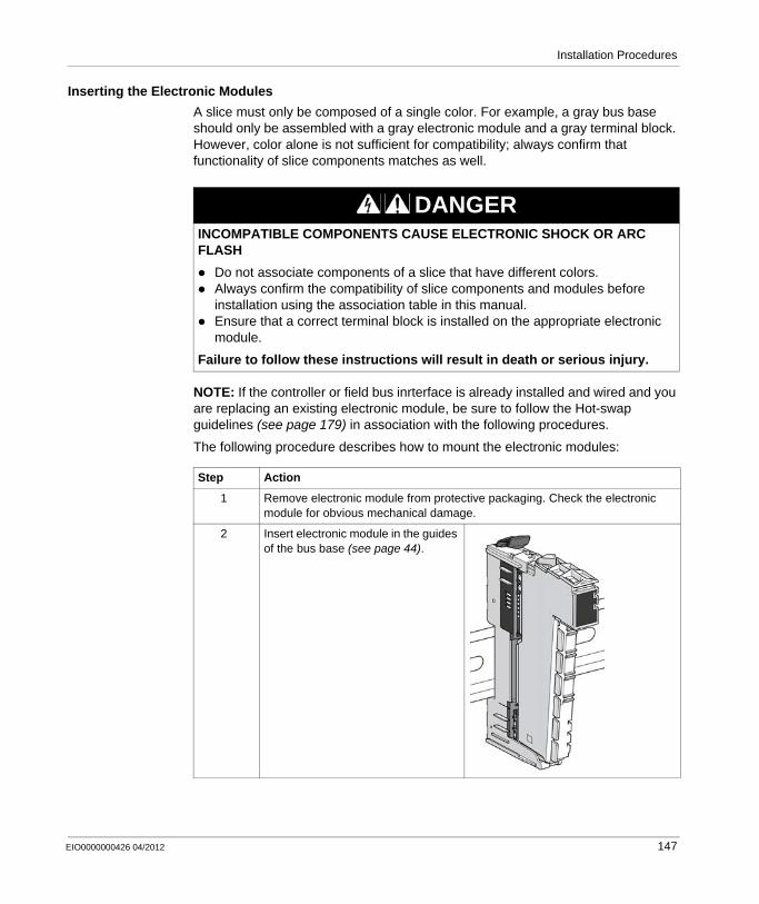
Installation Procedures
Inserting the Electronic Modules
A slice must only be composed of a single color. For example, a gray bus base should only be assembled with a gray electronic module and a gray terminal block. However, color alone is not sufficient for compatibility; always confirm that functionality of slice components matches as well.
NOTE: If the controller or field bus inrterface is already installed and wired and you are replacing an existing electronic module, be sure to follow the Hot-swap guidelines (see page 179) in association with the following procedures.
The following procedure describes how to mount the electronic modules:
DANGERINCOMPATIBLE COMPONENTS CAUSE ELECTRONIC SHOCK OR ARC FLASH
Do not associate components of a slice that have different colors.Always confirm the compatibility of slice components and modules before installation using the association table in this manual.Ensure that a correct terminal block is installed on the appropriate electronic module.
Failure to follow these instructions will result in death or serious injury.
Step Action
1 Remove electronic module from protective packaging. Check the electronic module for obvious mechanical damage.
2 Insert electronic module in the guides of the bus base (see page 44).
EIO0000000426 04/2012 147
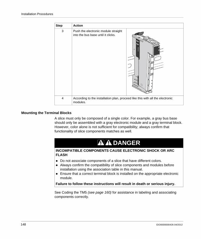
Installation Procedures
Mounting the Terminal Blocks
A slice must only be composed of a single color. For example, a gray bus base should only be assembled with a gray electronic module and a gray terminal block. However, color alone is not sufficient for compatibility; always confirm that functionality of slice components matches as well.
See Coding the TM5 (see page 160) for assistance in labeling and associating components correctly.
3 Push the electronic module straight into the bus base until it clicks.
4 According to the installation plan, proceed like this with all the electronic modules.
Step Action
DANGERINCOMPATIBLE COMPONENTS CAUSE ELECTRONIC SHOCK OR ARC FLASH
Do not associate components of a slice that have different colors.Always confirm the compatibility of slice components and modules before installation using the association table in this manual.Ensure that a correct terminal block is installed on the appropriate electronic module.
Failure to follow these instructions will result in death or serious injury.
148 EIO0000000426 04/2012
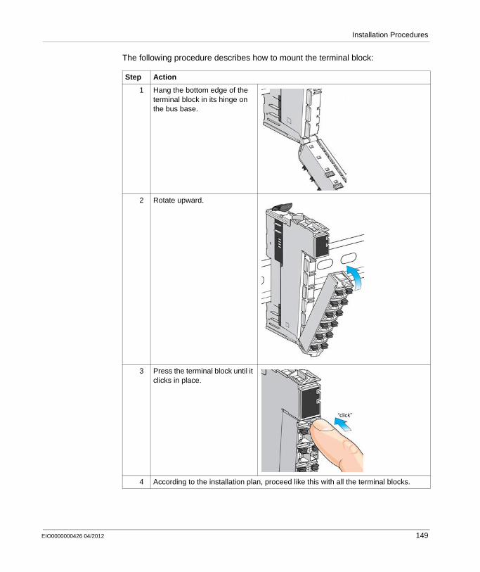
Installation Procedures
The following procedure describes how to mount the terminal block:
Step Action
1 Hang the bottom edge of the terminal block in its hinge on the bus base.
2 Rotate upward.
3 Press the terminal block until it clicks in place.
4 According to the installation plan, proceed like this with all the terminal blocks.
EIO0000000426 04/2012 149
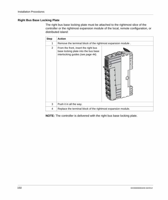
Installation Procedures
Right Bus Base Locking Plate
The right bus base locking plate must be attached to the rightmost slice of the controller or the rightmost expansion module of the local, remote configuration, or distributed island:
NOTE: The controller is delivered with the right bus base locking plate.
Step Action
1 Remove the terminal block of the rightmost expansion module .
2 From the front, insert the right bus base locking plate into the bus base interlocking guides (see page 44).
3 Push it in all the way.
4 Replace the terminal block of the rightmost expansion module.
150 EIO0000000426 04/2012
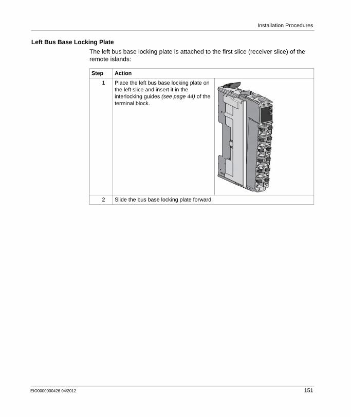
Installation Procedures
Left Bus Base Locking Plate
The left bus base locking plate is attached to the first slice (receiver slice) of the remote islands:
Step Action
1 Place the left bus base locking plate on the left slice and insert it in the interlocking guides (see page 44) of the terminal block.
2 Slide the bus base locking plate forward.
EIO0000000426 04/2012 151
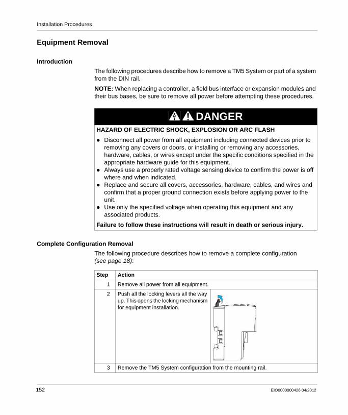
Installation Procedures
Equipment Removal
Introduction
The following procedures describe how to remove a TM5 System or part of a system from the DIN rail.
NOTE: When replacing a controller, a field bus interface or expansion modules and their bus bases, be sure to remove all power before attempting these procedures.
Complete Configuration Removal
The following procedure describes how to remove a complete configuration (see page 18):
DANGERHAZARD OF ELECTRIC SHOCK, EXPLOSION OR ARC FLASH
Disconnect all power from all equipment including connected devices prior to removing any covers or doors, or installing or removing any accessories, hardware, cables, or wires except under the specific conditions specified in the appropriate hardware guide for this equipment.Always use a properly rated voltage sensing device to confirm the power is off where and when indicated.Replace and secure all covers, accessories, hardware, cables, and wires and confirm that a proper ground connection exists before applying power to the unit.Use only the specified voltage when operating this equipment and any associated products.
Failure to follow these instructions will result in death or serious injury.
Step Action
1 Remove all power from all equipment.
2 Push all the locking levers all the way up. This opens the locking mechanism for equipment installation.
3 Remove the TM5 System configuration from the mounting rail.
152 EIO0000000426 04/2012
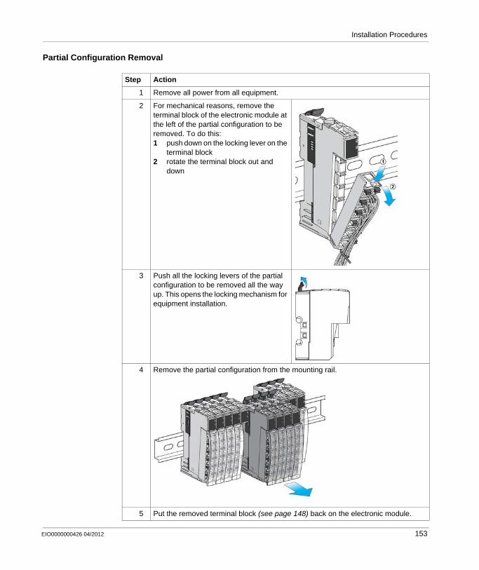
Installation Procedures
Partial Configuration Removal
Step Action
1 Remove all power from all equipment.
2 For mechanical reasons, remove the terminal block of the electronic module at the left of the partial configuration to be removed. To do this:1 push down on the locking lever on the
terminal block2 rotate the terminal block out and
down
3 Push all the locking levers of the partial configuration to be removed all the way up. This opens the locking mechanism for equipment installation.
4 Remove the partial configuration from the mounting rail.
5 Put the removed terminal block (see page 148) back on the electronic module.
EIO0000000426 04/2012 153
Installation Procedures
Expanding the TM5 System
How to Expand the TM5 System
When adding expansion modules be sure to remove all power before attempting these procedures.
DANGERHAZARD OF ELECTRIC SHOCK, EXPLOSION OR ARC FLASH
Disconnect all power from all equipment including connected devices prior to removing any covers or doors, or installing or removing any accessories, hardware, cables, or wires except under the specific conditions specified in the appropriate hardware guide for this equipment.Always use a properly rated voltage sensing device to confirm the power is off where and when indicated.Replace and secure all covers, accessories, hardware, cables, and wires and confirm that a proper ground connection exists before applying power to the unit.Use only the specified voltage when operating this equipment and any associated products.
Failure to follow these instructions will result in death or serious injury.
WARNINGUNINTENDED EQUIPMENT OPERATION
Only use software approved by Schneider Electric for use with this equipment.Update your application program every time you change the physical hardware configuration.
Failure to follow these instructions can result in death, serious injury, or equipment damage.
154 EIO0000000426 04/2012

Installation Procedures
The following procedure describes how to expand the TM5 System:
Step Action
1 Remove all power from all equipment.
2 Remove the terminal block from the rightmost slice:1 Push down on the locking
lever on the terminal block.2 Rotate the terminal block out
and down.
3 Remove the locking plate from the rightmost slice:1 Use a screwdriver to unhook
the locking clip of the right locking plate.
2 Pull the locking plate off the bus base and electronic module.
4 Install expansion modules according to your expansion layout as described in the slice (see page 145) or compact I/O (see page 143) installation procedures.Install the rightmost terminal block removed at the step 2.
5 Install the right locking plate (see page 150) to the rightmost expansion module of your new configuration.
EIO0000000426 04/2012 155
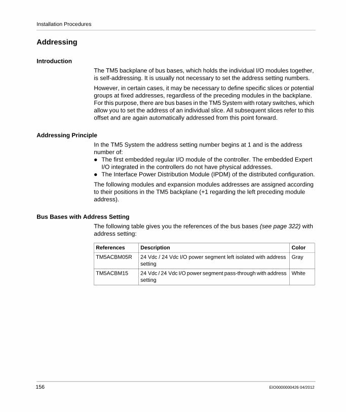
Installation Procedures
Addressing
Introduction
The TM5 backplane of bus bases, which holds the individual I/O modules together, is self-addressing. It is usually not necessary to set the address setting numbers.
However, in certain cases, it may be necessary to define specific slices or potential groups at fixed addresses, regardless of the preceding modules in the backplane. For this purpose, there are bus bases in the TM5 System with rotary switches, which allow you to set the address of an individual slice. All subsequent slices refer to this offset and are again automatically addressed from this point forward.
Addressing Principle
In the TM5 System the address setting number begins at 1 and is the address number of:
The first embedded regular I/O module of the controller. The embedded Expert I/O integrated in the controllers do not have physical addresses.The Interface Power Distribution Module (IPDM) of the distributed configuration.
The following modules and expansion modules addresses are assigned according to their positions in the TM5 backplane (+1 regarding the left preceding module address).
Bus Bases with Address Setting
The following table gives you the references of the bus bases (see page 322) with address setting:
References Description Color
TM5ACBM05R 24 Vdc / 24 Vdc I/O power segment left isolated with address setting
Gray
TM5ACBM15 24 Vdc / 24 Vdc I/O power segment pass-through with address setting
White
156 EIO0000000426 04/2012
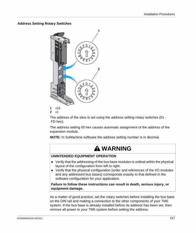
Installation Procedures
Address Setting Rotary Switches
1 x162 x1
The address of the slice is set using the address setting rotary switches (01 -FD hex).
The address setting 00 hex causes automatic assignment of the address of the expansion module.
NOTE: In SoMachine software the address setting number is in decimal.
As a matter of good practice, set the rotary switches before installing the bus base on the DIN rail and making a connection to the other components of your TM5 system. If the bus base is already installed before its address has been set, then remove all power to your TM5 system before setting the address.
WARNINGUNINTENDED EQUIPMENT OPERATION
Verify that the addressing of the bus base modules is ordinal within the physical layout of the configuration from left to right.Verify that the physical configuration (order and references of the I/O modules and any addressed bus bases) corresponds exactly to that defined in the software configuration for your application.
Failure to follow these instructions can result in death, serious injury, or equipment damage.
EIO0000000426 04/2012 157
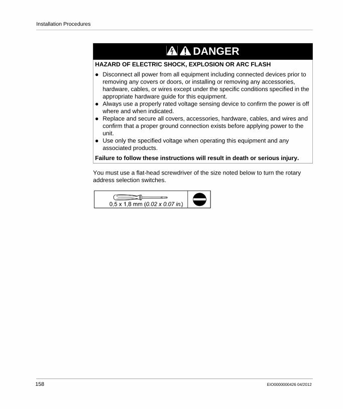
Installation Procedures
You must use a flat-head screwdriver of the size noted below to turn the rotary address selection switches.
DANGERHAZARD OF ELECTRIC SHOCK, EXPLOSION OR ARC FLASH
Disconnect all power from all equipment including connected devices prior to removing any covers or doors, or installing or removing any accessories, hardware, cables, or wires except under the specific conditions specified in the appropriate hardware guide for this equipment.Always use a properly rated voltage sensing device to confirm the power is off where and when indicated.Replace and secure all covers, accessories, hardware, cables, and wires and confirm that a proper ground connection exists before applying power to the unit.Use only the specified voltage when operating this equipment and any associated products.
Failure to follow these instructions will result in death or serious injury.
158 EIO0000000426 04/2012
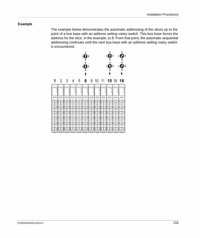
Installation Procedures
Example
The example below demonstrates the automatic addressing of the slices up to the point of a bus base with an address setting rotary switch. This bus base forces the address for the slice, in the example, to 8. From that point, the automatic sequential addressing continues until the next bus base with an address setting rotary switch is encountered.
EIO0000000426 04/2012 159
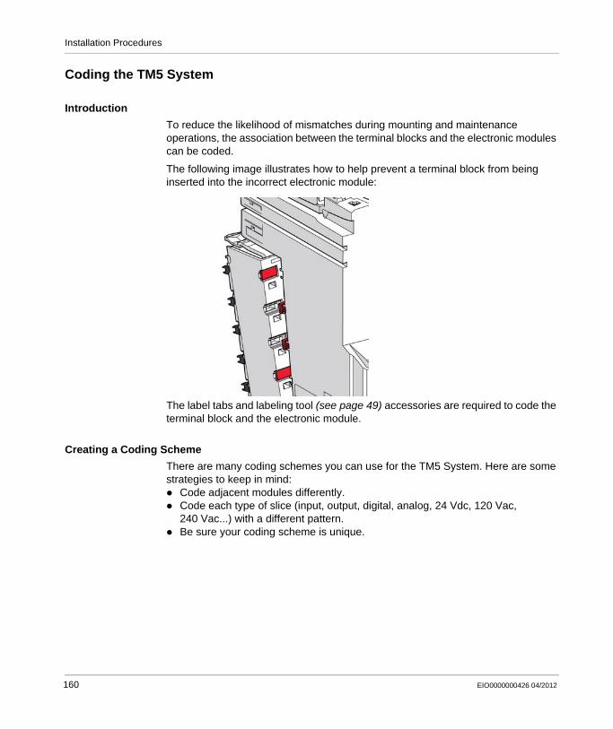
Installation Procedures
Coding the TM5 System
Introduction
To reduce the likelihood of mismatches during mounting and maintenance operations, the association between the terminal blocks and the electronic modules can be coded.
The following image illustrates how to help prevent a terminal block from being inserted into the incorrect electronic module:
The label tabs and labeling tool (see page 49) accessories are required to code the terminal block and the electronic module.
Creating a Coding Scheme
There are many coding schemes you can use for the TM5 System. Here are some strategies to keep in mind:
Code adjacent modules differently.Code each type of slice (input, output, digital, analog, 24 Vdc, 120 Vac, 240 Vac...) with a different pattern.Be sure your coding scheme is unique.
160 EIO0000000426 04/2012

Installation Procedures
The following table shows you some unique combinations to code your TM5 System:
1 2 3 4 5 6
A B A B A B A B A B A B
A Slots on the terminal blockB Slots on the electronic module
represents an electronic module slot (see page 45) with a label tab.
represents an electronic module slot without a label tab.
represents a terminal block slot (see page 46) with a label tab.
represents a terminal block slot without a label tab.
EIO0000000426 04/2012 161
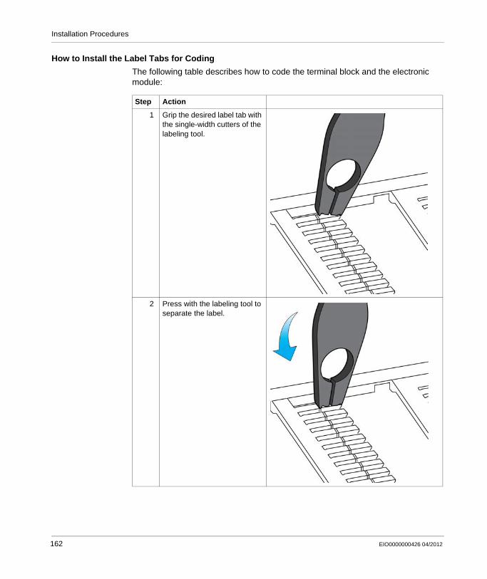
Installation Procedures
How to Install the Label Tabs for Coding
The following table describes how to code the terminal block and the electronic module:
Step Action
1 Grip the desired label tab with the single-width cutters of the labeling tool.
2 Press with the labeling tool to separate the label.
162 EIO0000000426 04/2012
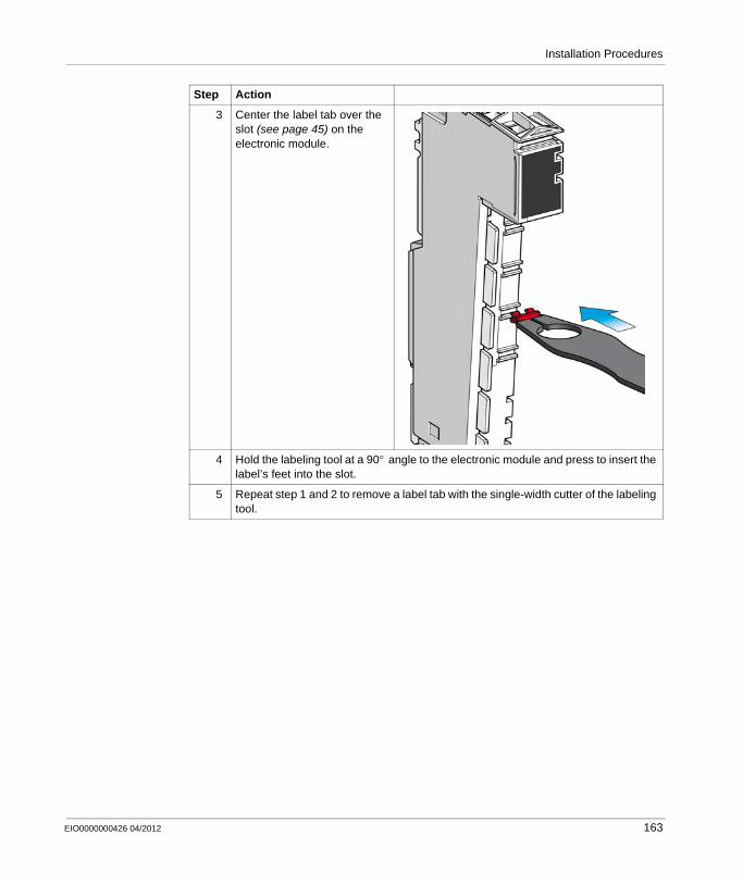
Installation Procedures
3 Center the label tab over the slot (see page 45) on the electronic module.
4 Hold the labeling tool at a 90° angle to the electronic module and press to insert the label’s feet into the slot.
5 Repeat step 1 and 2 to remove a label tab with the single-width cutter of the labeling tool.
Step Action
EIO0000000426 04/2012 163
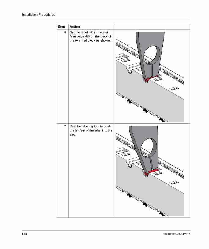
Installation Procedures
6 Set the label tab in the slot (see page 46) on the back of the terminal block as shown.
7 Use the labeling tool to push the left feet of the label into the slot.
Step Action
164 EIO0000000426 04/2012
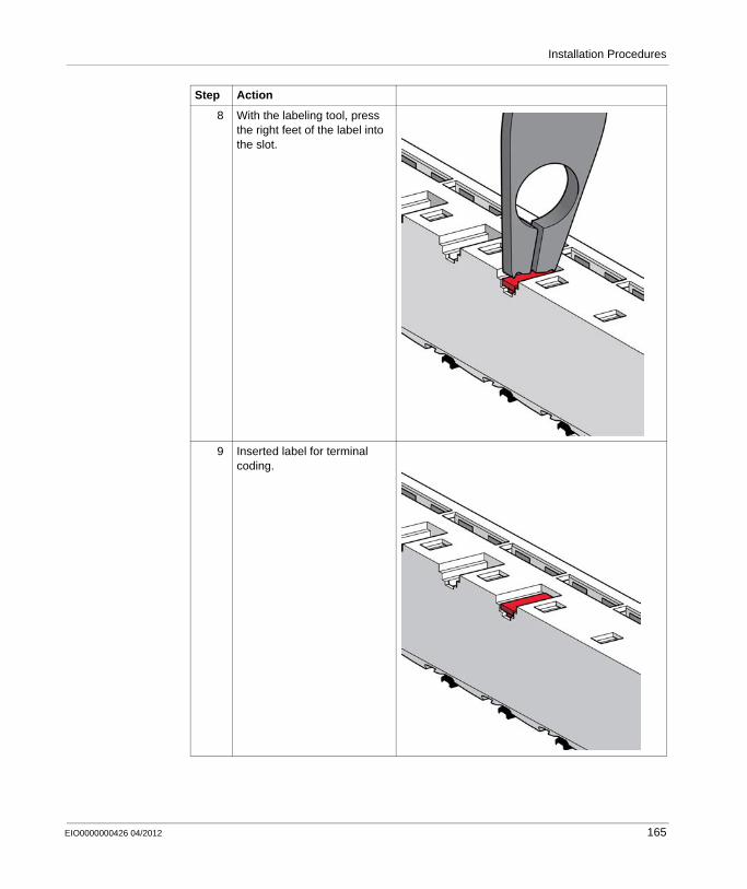
Installation Procedures
8 With the labeling tool, press the right feet of the label into the slot.
9 Inserted label for terminal coding.
Step Action
EIO0000000426 04/2012 165
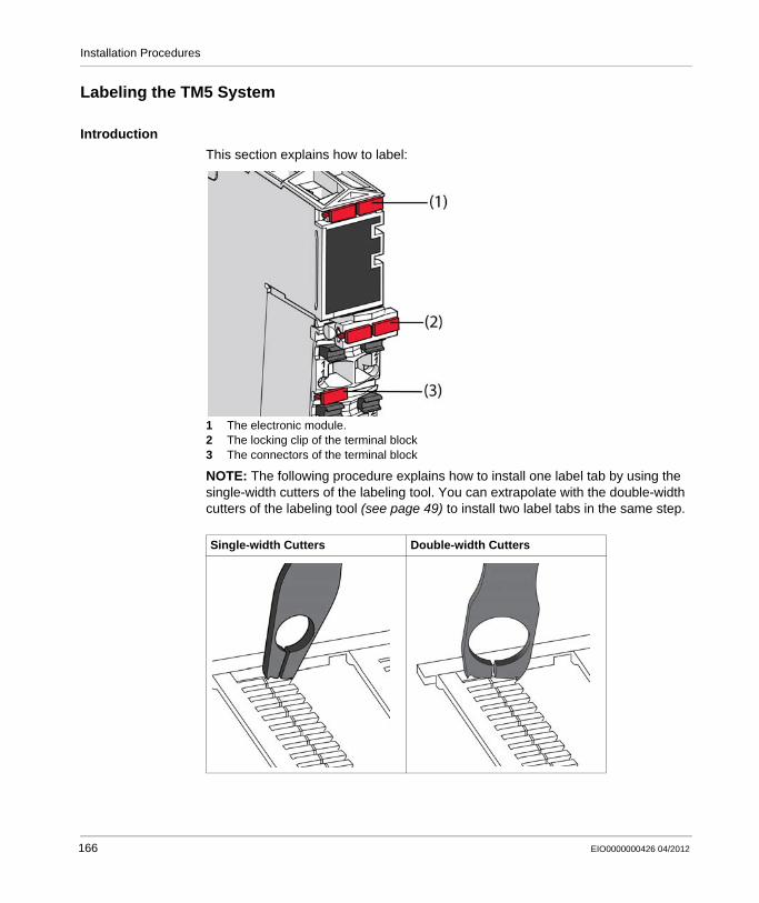
Installation Procedures
Labeling the TM5 System
Introduction
This section explains how to label:
1 The electronic module.2 The locking clip of the terminal block3 The connectors of the terminal block
NOTE: The following procedure explains how to install one label tab by using the single-width cutters of the labeling tool. You can extrapolate with the double-width cutters of the labeling tool (see page 49) to install two label tabs in the same step.
Single-width Cutters Double-width Cutters
166 EIO0000000426 04/2012

Installation Procedures
Labeling the Connectors of the Terminal Block
You can label the connectors of the terminal block as well as the locking clip of the terminal block itself.
The following table describes how to label the terminals of the terminal block:
Step Action
1 Grip the desired label tab with the single width cutters of the labeling tool.
2 Press with the labeling tool to separate the label.
EIO0000000426 04/2012 167
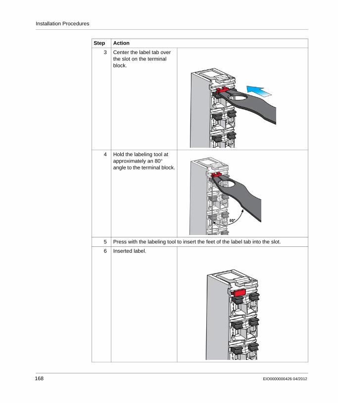
Installation Procedures
3 Center the label tab over the slot on the terminal block.
4 Hold the labeling tool at approximately an 80° angle to the terminal block.
5 Press with the labeling tool to insert the feet of the label tab into the slot.
6 Inserted label.
Step Action
168 EIO0000000426 04/2012
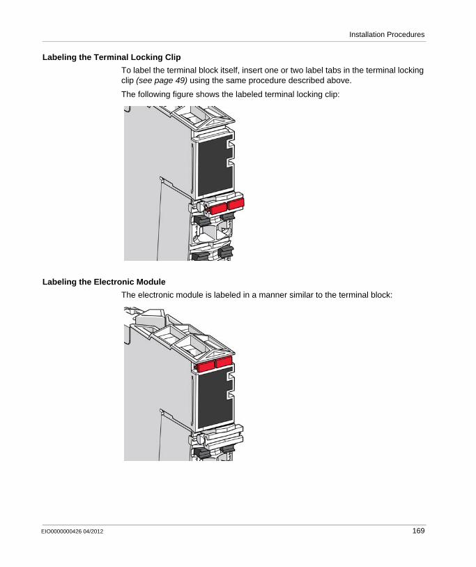
Installation Procedures
Labeling the Terminal Locking Clip
To label the terminal block itself, insert one or two label tabs in the terminal locking clip (see page 49) using the same procedure described above.
The following figure shows the labeled terminal locking clip:
Labeling the Electronic Module
The electronic module is labeled in a manner similar to the terminal block:
EIO0000000426 04/2012 169
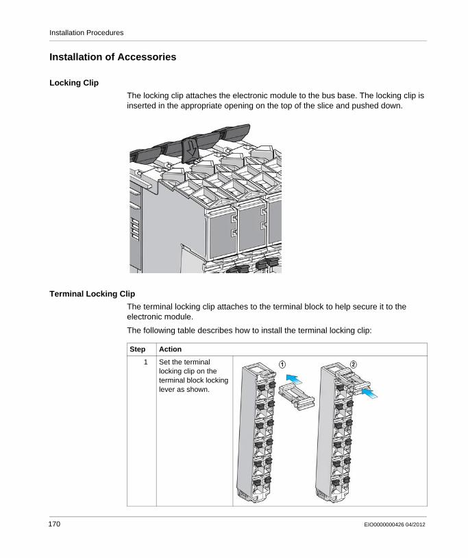
Installation Procedures
Installation of Accessories
Locking Clip
The locking clip attaches the electronic module to the bus base. The locking clip is inserted in the appropriate opening on the top of the slice and pushed down.
Terminal Locking Clip
The terminal locking clip attaches to the terminal block to help secure it to the electronic module.
The following table describes how to install the terminal locking clip:
Step Action
1 Set the terminal locking clip on the terminal block locking lever as shown.
170 EIO0000000426 04/2012

Installation Procedures
2 Push down and hold the terminal locking clip and the locking lever with your index finger. Slide the terminal locking clip forward with your thumb.
3 Hang the bottom edge of the terminal block in its hinge on the bus module.
Step Action
EIO0000000426 04/2012 171
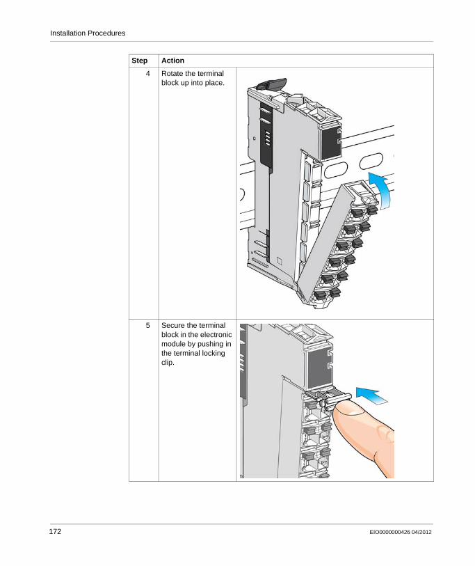
Installation Procedures
4 Rotate the terminal block up into place.
5 Secure the terminal block in the electronic module by pushing in the terminal locking clip.
Step Action
172 EIO0000000426 04/2012

Installation Procedures
Plain Text Cover
The covers are attached to the terminal locking clips:
6 Installed terminal locking clip.
7 To remove the terminal block, reverse Step 5 by pulling the terminal locking clip out.
Step Action
Step Action
1 Hold the plain text cover at a 90° angle to the terminal locking clip.
2 Push the plain text cover into the terminal locking clip until it clicks into the slot on the clip.
EIO0000000426 04/2012 173
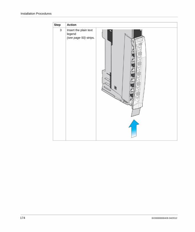
Installation Procedures
3 Insert the plain text legend (see page 50) strips.
Step Action
174 EIO0000000426 04/2012

EIO0000000426 04/2012
6
Modicon TM5 / TM7 Flexible System
Commissioning and Maintaining
EIO0000000426 04/2012
Commissioning and Maintaining
Overview
Once your TM5 System has been installed and you have confirmed that the installation has been properly grounded and powered, you can follow the procedures in this chapter to commission and maintain your configuration.
What’s in this Chapter?
This chapter contains the following topics:
Topic Page
Diagnostics 176
Hot Swapping Electronic Modules 179
175

Commissioning and Maintaining
Diagnostics
Introduction
The TM5 System offer several levels of diagnostics:Test points on the terminal blocksDirectly on the module using visual LED displaysVia SoMachine softwareWeb server
Test Points
Each terminal block (see page 46) has an access point for a test probe. You can easily measure the terminal potential without disconnecting the wire.
The following figure illustrates the use of the test probes:
Status LEDs
TM5 bus status, power, I/O status and channel states are displayed in direct relationship to the channels or the function. The different states are displayed differently, for example green for OK, red for detected error.
Refer to the hardware guides for the products of the TM5 System for status LEDs descriptions.
176 EIO0000000426 04/2012
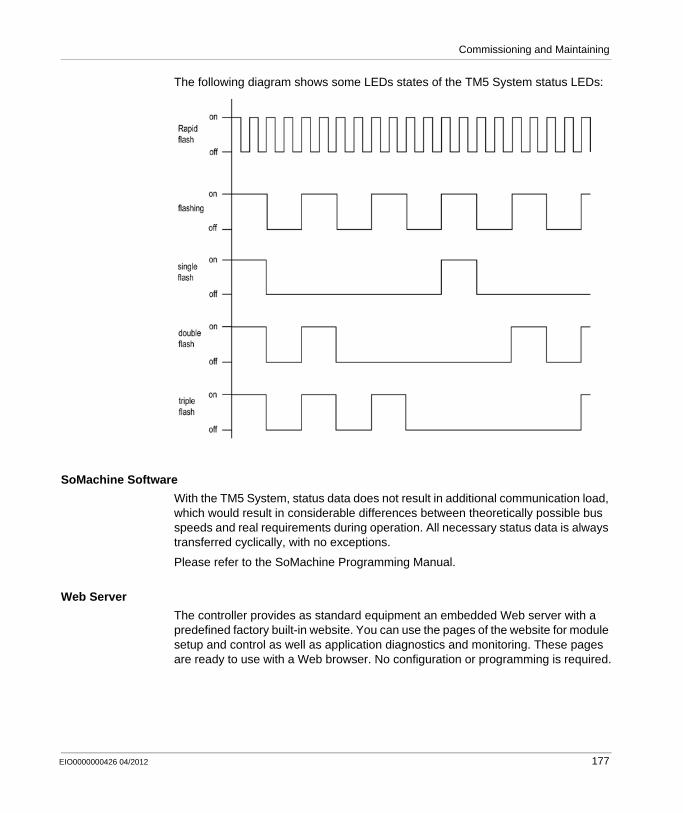
Commissioning and Maintaining
The following diagram shows some LEDs states of the TM5 System status LEDs:
SoMachine Software
With the TM5 System, status data does not result in additional communication load, which would result in considerable differences between theoretically possible bus speeds and real requirements during operation. All necessary status data is always transferred cyclically, with no exceptions.
Please refer to the SoMachine Programming Manual.
Web Server
The controller provides as standard equipment an embedded Web server with a predefined factory built-in website. You can use the pages of the website for module setup and control as well as application diagnostics and monitoring. These pages are ready to use with a Web browser. No configuration or programming is required.
EIO0000000426 04/2012 177
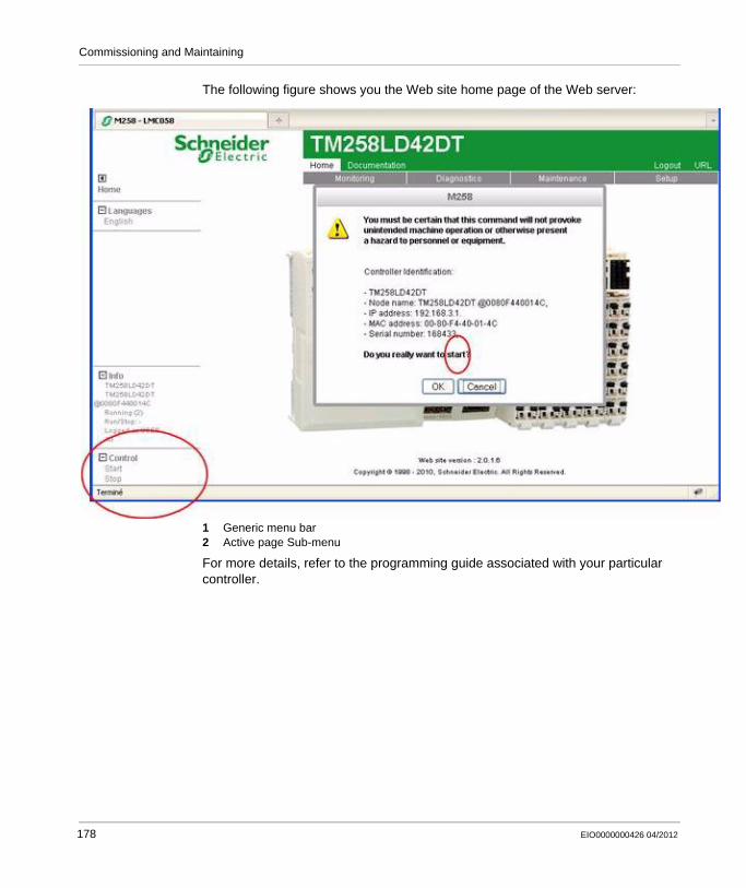
Commissioning and Maintaining
The following figure shows you the Web site home page of the Web server:
1 Generic menu bar2 Active page Sub-menu
For more details, refer to the programming guide associated with your particular controller.
178 EIO0000000426 04/2012
Commissioning and Maintaining
Hot Swapping Electronic Modules
Definition
Hot swapping is the ability to remove an I/O electronic module from its bus base and then replace it with an identical electronic module while the TM5 System is under power without disrupting the normal operations of the controller. When the electronic module is returned to its bus base or replaced with another electronic module with the same reference, it starts to operate again.
Hot Swapping Considerations
Before initiating a hot swap operation, confirm that the electronic module type is approved for hot swapping (see page 181).
When removing or inserting an I/O module while power is applied, remove and insert the electronic module by hand. Do not use tools to hot swap modules because they may come into contact with hazardous voltages. Also, remove any locking clips and the terminal block before removing the electronic module from its bus base. Hot swapping is only allowed when replacing identical electronic modules.
NOTE: Only the electronic module is hot swap-able. Do not attempt a hot swap operation on the bus base, or on electronic modules that are integrated with their bus bases such as the compact I/O.
You need to understand and plan for the consequences of hot-swapping certain modules. Hot-swapping modules that control power distribution to other modules, for example, can impact your machine or process. Power Distribution modules, Interface Power Distribution Modules, Common Distribution modules, Field Bus Interface Modules, and Transmitter and Receiver modules all either distribute power or communications to other electronic modules. Disconnecting the connector to these modules will interrupt power or communications to the modules they service.
DANGEREXPLOSION OR ELECTRIC SHOCK
Only perform a hot swap operation in locations known to be non-hazardous.Use only your hands.Do not use any metal tools.Do not disconnect any wires from the terminal block.Only replace an electronic module with an identical reference.
Failure to follow these instructions will result in death or serious injury.
EIO0000000426 04/2012 179
Commissioning and Maintaining
For example, some Power Distribution Modules (PDMs) provide power to both the TM5 power bus and 24 Vdc I/O power segment. It is possible that you may need to replace the PDM because one service is inoperable, but not both. In this case, hot-swapping the PDM would interrupt the service that is still operating, and would interrupt power to the modules drawing power from that service.
I/O configurations that employ Common Distribution modules require careful consideration when wiring is restricted by short wire lengths. It may be the case that in order to hot-swap an electronic module that has become inoperable, you need to disconnect the connector of the Common module servicing it. Further, that same Common module may be connected to modules or devices other than the module you wish to hot-swap. Disconnecting the Common module in this case would necessarily interrupt the supply to the unaffected modules and/or devices. Be sure that you know what I/O slices or devices are connected to the Common module, and the impact that this disconnection would have on your machine or process before attempting a hot-swap operation.
1 For additional information, refer to NEMA ICS 1.1 (latest edition), "Safety Guidelines for the Application, Installation, and Maintenance of Solid State Control" and to NEMA ICS 7.1 (latest edition), "Safety Standards for Construction and Guide for Selection, Installation and Operation of Adjustable-Speed Drive Systems" or their equivalent governing your particular location.
NOTE: Be sure you thoroughly understand the consequences of a hot-swap operation on all modules and connected devices as they relate to your machine or process.
WARNINGLOSS OF CONTROL
The designer of any control scheme must consider the potential failure modes of control paths and, for certain critical control functions, provide a means to achieve a safe state during and after a path failure. Examples of critical control functions are emergency stop and overtravel stop, power outage and restart.Separate or redundant control paths must be provided for critical control functions.System control paths may include communication links. Consideration must be given to the implications of unanticipated transmission delays or failures of the link.
Observe all accident prevention regulations and local safety guidelines.1
Each implementation of this equipment must be individually and thoroughly tested for proper operation before being placed into service.
Failure to follow these instructions can result in death, serious injury, or equipment damage.
180 EIO0000000426 04/2012
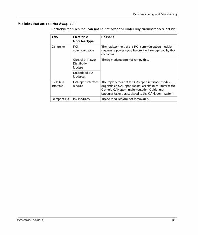
Commissioning and Maintaining
Modules that are not Hot Swap-able
Electronic modules that can not be hot swapped under any circumstances include:
TM5 Electronic Modules Type
Reasons
Controller PCI communication
The replacement of the PCI communication module requires a power cycle before it will recognized by the controller.
Controller Power Distribution Module
These modules are not removable.
Embedded I/O Modules
Field bus interface
CANopen interface module
The replacement of the CANopen interface module depends on CANopen master architecture. Refer to the Generic CANopen Implementation Guide and documentations associated to the CANopen master.
Compact I/O I/O modules These modules are not removable.
EIO0000000426 04/2012 181

Commissioning and Maintaining
182 EIO0000000426 04/2012

EIO0000000426 04/2012
III
Modicon TM5 / TM7 Flexible System
TM7 System
EIO0000000426 04/2012
TM7 System
Overview
Part III of this manual provides information to help you plan, install, commission, and maintain your TM7 System.
What’s in this Part?
This part contains the following chapters:
Chapter Chapter Name Page
7 Initial Planning Considerations 185
8 Installation Procedures 223
9 Commissioning and Maintaining 237
183

TM7 System
184 EIO0000000426 04/2012

EIO0000000426 04/2012
7
Modicon TM5 / TM7 Flexible System
Planning
EIO0000000426 04/2012
Initial Planning Considerations
Overview
This chapter provides information that is helpful in the early planning stages for a TM7 System. It includes the requirements for mounting and wiring the TM7 System and for determining the type of power supply source required for the configuration you choose.
What’s in this Chapter?
This chapter contains the following sections:
Section Topic Page
7.1 Operating Environment 186
7.2 Mechanical Requirements 189
7.3 TM7 Power System 192
7.4 Electrical Requirements 211
185

Planning
7.1 Operating Environment
Environmental Characteristics
Introduction
The following information describes the system-wide environmental requirements and characteristics for the TM7 System.
The general environmental characteristics are common to all components of the TM7 System.
Environmental Characteristics
This equipment meets cURus, GOST-R and c-Tick certifications and CE requirements as indicated in the table below. This equipment is intended for use in a Pollution Degree 2 industrial environment.
The table below provides the general environmental characteristics:
Characteristic Specification
This product is compliant with Europe RoHS recommendations and China RoHS regulations.
II 3G Device group II, Category 3, Zone 2 suitable for explosive gas
Ex Protection according to European standards
nA Ignition protection "n"
T5 Temperature class
T84 ° C Maximum surface temperature
IP67 Protection index according to EN/IEC 60529
Ta = 0...60 ° C
(32...140 ° F)1Ambient temperature range
TÜV 05 ATEX 7201 Certificate number
Standard IEC61131-2 ed. 3 2007
Agencies UL 508CSA 22.2 No. 142-M1987CSA 22.2 No. 213-M1987
Ambient operating temperature -10...60 ° C (14...140 ° F)1
Storage temperature -25...85 ° C (-13...185 ° F)
Relative humidity 5...95% (non-condensing)
186 EIO0000000426 04/2012
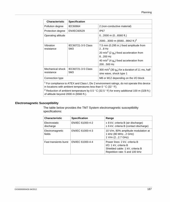
Planning
Electromagnetic Susceptibility
The table below provides the TM7 System electromagnetic susceptibility specifications:
Pollution degree IEC60664 2 (non-conductive material)
Protection degree EN/IEC60529 IP67
Operating altitude 0...2000 m (0...6560 ft.)
2000...3000 m (6560...9842 ft.)2
Vibration resistance
IEC60721-3-5 Class 5M3
7.5 mm (0.295 in.) fixed amplitude from 2...8 Hz
20 m/s2 (2 gn) fixed acceleration from 8...200 Hz
40 m/s2 (4 gn) fixed acceleration from 200...500 Hz
Mechanical shock resistance
IEC60721-3-5 Class 5M3
300 m/s2 (30 gn) for a duration of 11 ms, half sine wave, shock type 1
Connection type M8 or M12 depending on the I/O block
1 For compliance to ATEX and Class I, Div 2 environment ratings, do not operate this device in locations with ambient temperatures less than 0 ° C (32 ° F).2 Reduction of ambient temperature by 0.5 ° C (32.5 ° F) for every additional 100 m (328 ft.) of altitude beyond 2000 m (6560 ft.).
Characteristic Specification
Characteristic Specification Range
Electrostatic discharge
EN/IEC 61000-4-2 ± 8 kV, criteria B (air discharge)± 6 kV, criteria B (contact discharge)
Electromagnetic fields
EN/IEC 61000-4-3 10 V/m, 80% amplitude modulation at 1 kHz (80 MHz...2 GHz)1 V/m (2...2.7 GHz)
Fast transients burst EN/IEC 61000-4-4 Power lines: 2 kV, criteria BI/O: 1 kV, criteria BShielded cable: 1 kV, criteria BRepetition rate: 5 and 100 kHz
EIO0000000426 04/2012 187

Planning
Conformity and Test Certification
These devices were developed and tested according to valid European guidelines and standards. Modules labelled ATEX meet the following EU guidelines including all changes:
Surge immunity 24 Vdc circuit
EN/IEC 61000-4-5 Power lines: 1 kV (12 Ω), criteria B in common mode0.5 kV (2 Ω), criteria B in differential mode
Unshielded lines: 0.5 kV (42 Ω), criteria B in common mode1 kV (42 Ω), criteria B in differential mode
Shielded lines: 1 kV (12 Ω), criteria B in common mode0.5 kV (2 Ω), criteria B in differential mode
Induced electromagnetic field
EN/IEC 61000-4-6 Network, I/O signal connections > 10 m (32.8 ft.), functional ground connection:10 Veff, criteria A, 80% amplitude modulation at 1 kHz (150...80 MHz)
Conducted emission EN 55011 (IEC/CISPR11) 150...500 kHzquasi peak 79 dB µV
500 kHz...30 MHzquasi peak 73 dB µV
Radiated emission EN 55011 (IEC/CISPR11) 30...230 MHz,10 m (32.8 ft)@40 dB (µV/m)
230 MHz...1 GHz,10 m (32.8 ft)@47 dB (µV/m)
Characteristic Specification Range
Characteristic Specification
Electromagnetic compatibility (EMC) 2004/108/EC
Low voltage (LV) 2006/95/EC
Equipment explosive atmospheres (ATEX)
94/9/EC
Standards met EN 61131-2, EN 61000-6-2, EN 61000-6-4, EN 60204-1, EN 50178, EN 60079-15
188 EIO0000000426 04/2012
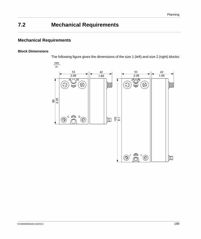
Planning
7.2 Mechanical Requirements
Mechanical Requirements
Block Dimensions
The following figure gives the dimensions of the size 1 (left) and size 2 (right) blocks:
EIO0000000426 04/2012 189
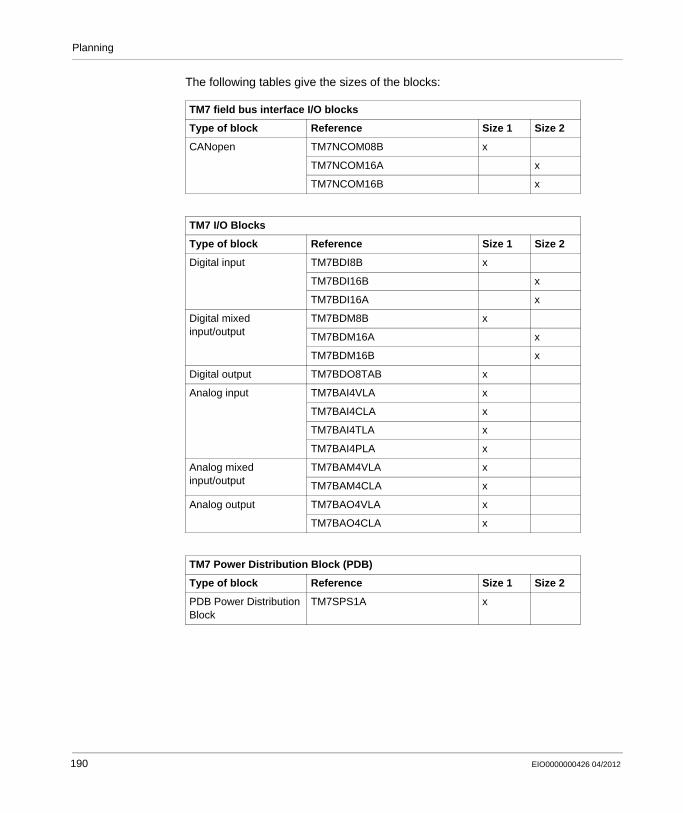
Planning
The following tables give the sizes of the blocks:
TM7 field bus interface I/O blocks
Type of block Reference Size 1 Size 2
CANopen TM7NCOM08B x
TM7NCOM16A x
TM7NCOM16B x
TM7 I/O Blocks
Type of block Reference Size 1 Size 2
Digital input TM7BDI8B x
TM7BDI16B x
TM7BDI16A x
Digital mixed input/output
TM7BDM8B x
TM7BDM16A x
TM7BDM16B x
Digital output TM7BDO8TAB x
Analog input TM7BAI4VLA x
TM7BAI4CLA x
TM7BAI4TLA x
TM7BAI4PLA x
Analog mixed input/output
TM7BAM4VLA x
TM7BAM4CLA x
Analog output TM7BAO4VLA x
TM7BAO4CLA x
TM7 Power Distribution Block (PDB)
Type of block Reference Size 1 Size 2
PDB Power Distribution Block
TM7SPS1A x
190 EIO0000000426 04/2012
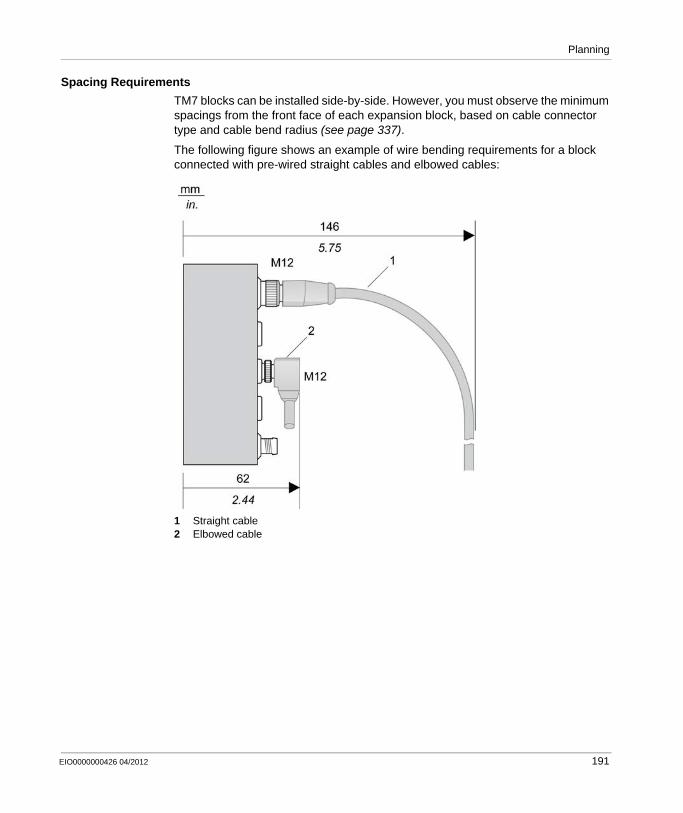
Planning
Spacing Requirements
TM7 blocks can be installed side-by-side. However, you must observe the minimum spacings from the front face of each expansion block, based on cable connector type and cable bend radius (see page 337).
The following figure shows an example of wire bending requirements for a block connected with pre-wired straight cables and elbowed cables:
1 Straight cable2 Elbowed cable
EIO0000000426 04/2012 191
Planning
7.3 TM7 Power System
Introduction
In the planning phase, the number of I/O blocks that you select for your TM7 System, and the cable lengths between these blocks, determine the required power distribution. The following section helps you establish a power budget and select the correct power distribution and I/O blocks for your system.
What’s in this Section?
This section contains the following topics:
Topic Page
TM7 Power Distribution Description 193
TM7 Power Distribution System Implementation 198
Example 1: Current Consumed by a TM7 Distributed I/O Configuration 199
Example 2: Current Consumed by a Remote Configuration 205
192 EIO0000000426 04/2012
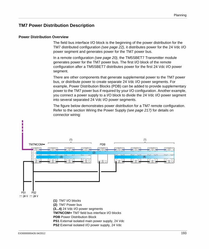
Planning
TM7 Power Distribution Description
Power Distribution Overview
The field bus interface I/O block is the beginning of the power distribution for the TM7 distributed configuration (see page 22), it distributes power for the 24 Vdc I/O power segment and generates power for the TM7 power bus.
In a remote configuration (see page 20), the TM5SBET7 Transmitter module generates power for the TM7 power bus. The first I/O block of the remote configuration after a TM5SBET7 distributes power for the first 24 Vdc I/O power segment.
There are other components that generate supplemental power to the TM7 power bus, or distribute power to create separate 24 Vdc I/O power segments. For example, Power Distribution Blocks (PDB) can be added to provide supplementary power to the TM7 power bus if required by your I/O configuration. Another example, you connect a power supply to a I/O block to divide the 24 Vdc I/O power segment into several separated 24 Vdc I/O power segments.
The figure below demonstrates power distribution for a TM7 remote configuration. Refer to the section Wiring the Power Supply (see page 217) for details on connector wiring:
(1) TM7 I/O blocks(2) TM7 Power bus(3...4) 24 Vdc I/O power segmentsTM7NCOM•• TM7 field bus interface I/O blocksPDB Power Distribution BlockPS1 External isolated main power supply, 24 VdcPS2 External isolated I/O power supply, 24 Vdc
EIO0000000426 04/2012 193
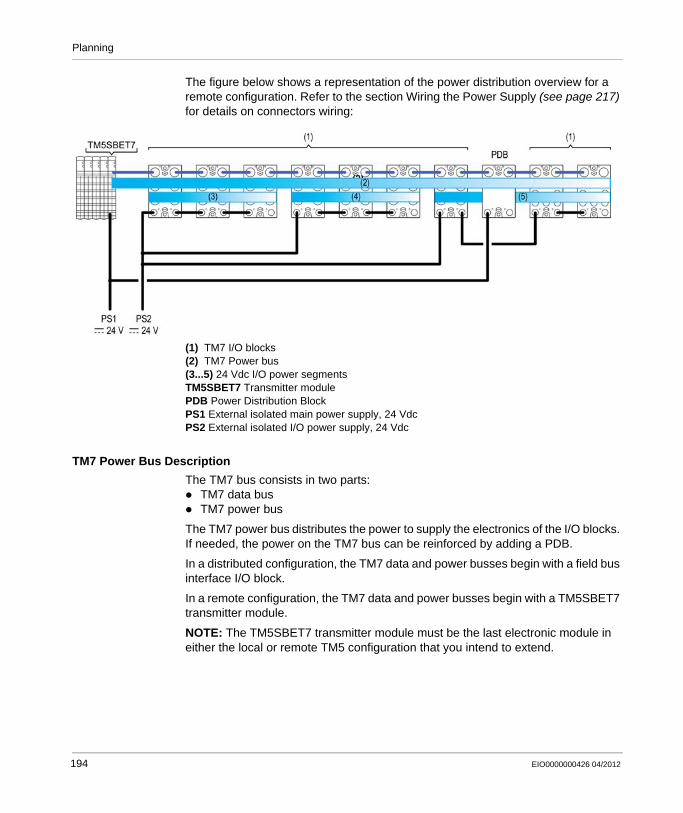
Planning
The figure below shows a representation of the power distribution overview for a remote configuration. Refer to the section Wiring the Power Supply (see page 217) for details on connectors wiring:
(1) TM7 I/O blocks(2) TM7 Power bus(3...5) 24 Vdc I/O power segmentsTM5SBET7 Transmitter modulePDB Power Distribution BlockPS1 External isolated main power supply, 24 VdcPS2 External isolated I/O power supply, 24 Vdc
TM7 Power Bus Description
The TM7 bus consists in two parts:TM7 data busTM7 power bus
The TM7 power bus distributes the power to supply the electronics of the I/O blocks. If needed, the power on the TM7 bus can be reinforced by adding a PDB.
In a distributed configuration, the TM7 data and power busses begin with a field bus interface I/O block.
In a remote configuration, the TM7 data and power busses begin with a TM5SBET7 transmitter module.
NOTE: The TM5SBET7 transmitter module must be the last electronic module in either the local or remote TM5 configuration that you intend to extend.
194 EIO0000000426 04/2012
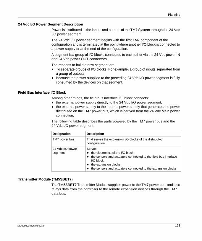
Planning
24 Vdc I/O Power Segment Description
Power is distributed to the inputs and outputs of the TM7 System through the 24 Vdc I/O power segment.
The 24 Vdc I/O power segment begins with the first TM7 component of the configuration and is terminated at the point where another I/O block is connected to a power supply or at the end of the configuration.
A segment is a group of I/O blocks connected to each other via the 24 Vdc power IN and 24 Vdc power OUT connectors.
The reasons to build a new segment are:To separate groups of I/O blocks. For example, a group of inputs separated from a group of outputs.Because the power supplied to the preceding 24 Vdc I/O power segment is fully consumed by the devices on that segment.
Field Bus Interface I/O Block
Among other things, the field bus interface I/O block connects:the external power supply directly to the 24 Vdc I/O power segment,the external power supply to the internal power supply that generates the power distributed on the TM7 power bus, which is derived from the 24 Vdc Main power connection.
The following table describes the parts powered by the TM7 power bus and the 24 Vdc I/O power segment:
Transmitter Module (TM5SBET7)
The TM5SBET7 Transmitter Module supplies power to the TM7 power bus, and also relays data from the controller to the remote expansion devices through the TM7 data bus.
Designation Description
TM7 power bus That serves the expansion I/O blocks of the distributed configuration.
24 Vdc I/O power segment
Serves:the electronics of the I/O block,the sensors and actuators connected to the field bus interface I/O block,the expansion blocks,the sensors and actuators connected to the expansion blocks.
EIO0000000426 04/2012 195

Planning
Depending on the mounting position of the TM5SBET7 transmitter module, the number of TM7 expansion I/O blocks connected without a PDB is limited to:
NOTE: To install more than 6 or 8 blocks (according to the installation orientation of the TM5SBET7) of TM7 remote I/O, you will need to add a Power Distribution Block.
Power Distribution Block (PDB)
The Power Distribution Blocks (PDBs) are used to reinforce the voltages and currents distributed by the TM7 power bus. Any of the following may require you to add PDBs to reinforce the TM7 power bus:
No PDBs have been installed, and the number of I/O blocks exceeds the maximum number that can be supported by the TM5SBET7 transmitter module based on installation orientation. For more information, refer to Transmitter Module (see page 195).The installed transmitter module and PDBs are adequate to the I/O block current consumption and cable lengths, but you desire redundant power in the event a PDB becomes inoperative. The cumulative power consumption of the I/O block electronics exceeds the maximum output current available from the TM5SBET7 transmitter module and any PDBs already installed. For more information, refer to Current Supplied and Consumption Tables on the TM7 Power Bus (see page 257).
TM5SBET7 Position Maximum Number of TM7 I/O Blocks
Horizontal 8
Vertical 6
WARNINGUNINTENDED EQUIPMENT OPERATION
Do not connect more than 8 blocks to a TM5SBET7 installed in a horizontal orientation.Do not connect more than 6 blocks to a TM5SBET7 installed in a vertical orientation.
Failure to follow these instructions can result in death, serious injury, or equipment damage.
196 EIO0000000426 04/2012
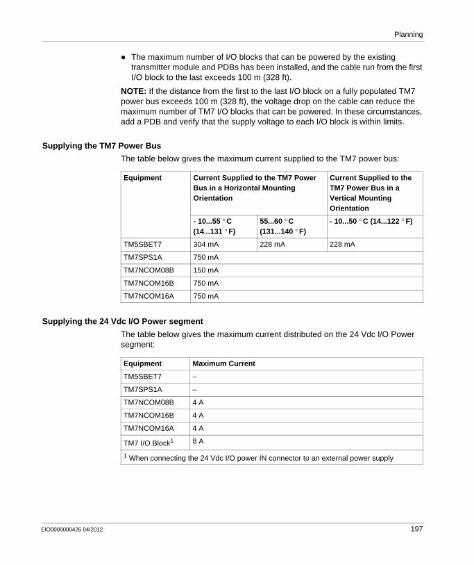
Planning
The maximum number of I/O blocks that can be powered by the existing transmitter module and PDBs has been installed, and the cable run from the first I/O block to the last exceeds 100 m (328 ft).
NOTE: If the distance from the first to the last I/O block on a fully populated TM7 power bus exceeds 100 m (328 ft), the voltage drop on the cable can reduce the maximum number of TM7 I/O blocks that can be powered. In these circumstances, add a PDB and verify that the supply voltage to each I/O block is within limits.
Supplying the TM7 Power Bus
The table below gives the maximum current supplied to the TM7 power bus:
Supplying the 24 Vdc I/O Power segment
The table below gives the maximum current distributed on the 24 Vdc I/O Power segment:
Equipment Current Supplied to the TM7 Power Bus in a Horizontal Mounting Orientation
Current Supplied to the TM7 Power Bus in a Vertical Mounting Orientation
- 10...55 ° C (14...131 ° F)
55...60 ° C (131...140 ° F)
- 10...50 ° C (14...122 ° F)
TM5SBET7 304 mA 228 mA 228 mA
TM7SPS1A 750 mA
TM7NCOM08B 150 mA
TM7NCOM16B 750 mA
TM7NCOM16A 750 mA
Equipment Maximum Current
TM5SBET7 –
TM7SPS1A –
TM7NCOM08B 4 A
TM7NCOM16B 4 A
TM7NCOM16A 4 A
TM7 I/O Block1 8 A
1 When connecting the 24 Vdc I/O power IN connector to an external power supply
EIO0000000426 04/2012 197
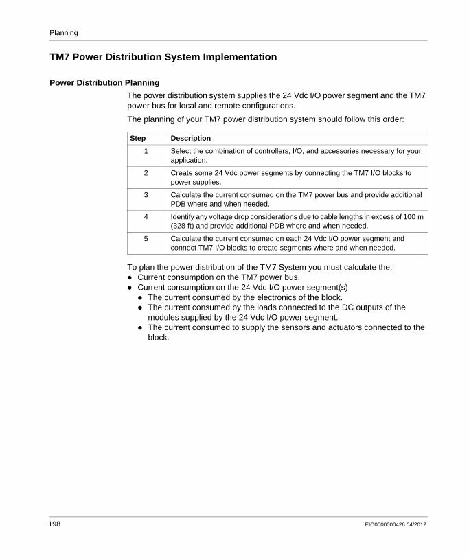
Planning
TM7 Power Distribution System Implementation
Power Distribution Planning
The power distribution system supplies the 24 Vdc I/O power segment and the TM7 power bus for local and remote configurations.
The planning of your TM7 power distribution system should follow this order:
To plan the power distribution of the TM7 System you must calculate the:Current consumption on the TM7 power bus.Current consumption on the 24 Vdc I/O power segment(s)
The current consumed by the electronics of the block.The current consumed by the loads connected to the DC outputs of the modules supplied by the 24 Vdc I/O power segment.The current consumed to supply the sensors and actuators connected to the block.
Step Description
1 Select the combination of controllers, I/O, and accessories necessary for your application.
2 Create some 24 Vdc power segments by connecting the TM7 I/O blocks to power supplies.
3 Calculate the current consumed on the TM7 power bus and provide additional PDB where and when needed.
4 Identify any voltage drop considerations due to cable lengths in excess of 100 m (328 ft) and provide additional PDB where and when needed.
5 Calculate the current consumed on each 24 Vdc I/O power segment and connect TM7 I/O blocks to create segments where and when needed.
198 EIO0000000426 04/2012
Planning
Example 1: Current Consumed by a TM7 Distributed I/O Configuration
Introduction
This first example is for a TM7 distributed I/O configuration (TM7 field bus interface I/O block and TM7 I/O blocks). A later example (see page 103) is based on TM7 remote expansion I/O blocks (TM5 Transmitter module and its remote expansion blocks). From these examples, you should be able to make the calculations necessary for your TM7 System.
In a TM7 distributed I/O configuration, the TM7 field bus interface I/O block connects:
the external power supply directly to the 24 Vdc I/O power segment,the external power supply to the internal power supply that generates the power distributed on the TM7 power bus, which is derived from the 24 Vdc Main power connection.
All current consumption values are documented in the chapter Association and Power Consumption Tables (see page 241).
Planning Example
This configuration example includes:The CANopen interface I/O block TM7NCOM08B equipped with 8 digital input or output configurable channels.Some expansion blocks:
TM7BDI8BTM7BDI16BTM7BDM16ATM7BDM16BTM7BDO8TABTM7BAI4CLATM7BAO4CLA
Assumptions used for the purposes of calculating the consumption of this example:TM7NCOM08B: The maximum current distributed on the 24 Vdc I/O power
segment is limited by an external isolated power supply of 4000 mA.TM7BDI8B: The current to supply the electronic sensors of this example has
been estimated at 25 mA per sensor, or 200 mA total for the block.TM7BDM16A: The sum of the current draw for all outputs connected to the block
is never more than 2500 mA at any given time.TM7BDM16B: The sum of the current draw for all outputs connected to the block
is never more than 1500 mA at any given time.The current to supply the electronic sensors of this example has been estimated at 25 mA per sensor, or 200 mA total for the block.
EIO0000000426 04/2012 199
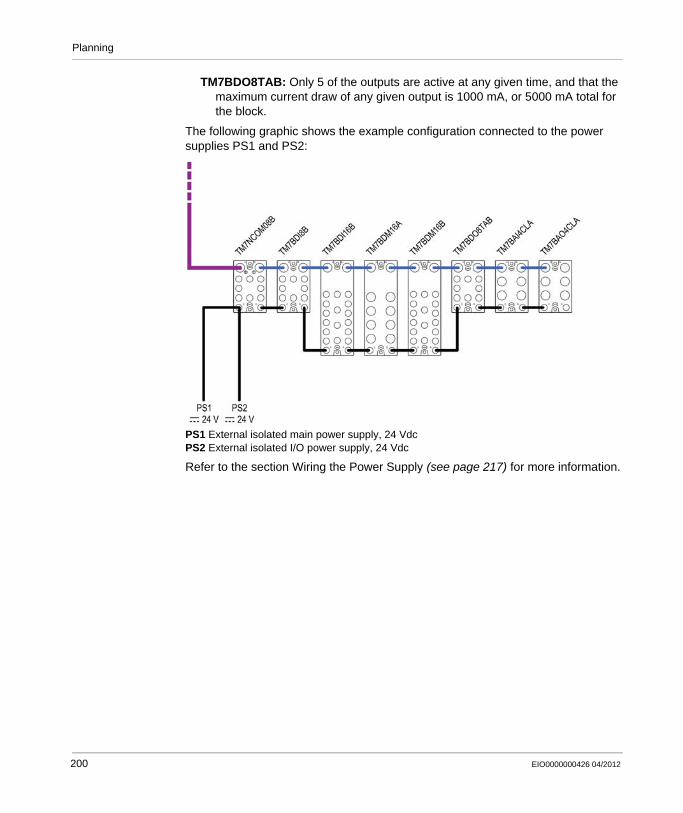
Planning
TM7BDO8TAB: Only 5 of the outputs are active at any given time, and that the maximum current draw of any given output is 1000 mA, or 5000 mA total for the block.
The following graphic shows the example configuration connected to the power supplies PS1 and PS2:
PS1 External isolated main power supply, 24 VdcPS2 External isolated I/O power supply, 24 Vdc
Refer to the section Wiring the Power Supply (see page 217) for more information.
200 EIO0000000426 04/2012

Planning
The following table shows the current supplied and consumed in mA on the TM7 power bus and the 24 Vdc I/O power segment:
Current Consumed on the TM7 Power Bus
The TM7NCOM08B generates 150 mA on the TM7 power bus to supply expansion blocks. The TM7 power bus begins with the TM7NCOM08B block and terminates with the TM7BAO4CLA expansion block.
The total current consumed on the TM7 power bus is 266 mA and exceeds the 150 mA capacity of the segment.
Observing mounting PDBs rules (see page 196), you must supplement the TM7 power bus by adding a TM7SPS1A. For example you can place the TM7SPS1A between a TM7BDM16B and a TM7BDM16A blocks.
TM
7NC
OM
08B
TM
7BD
I8B
TM
7BD
I16B
TM
7BD
M16
A
TM
7BD
M16
B
TM
7BD
O8T
AB
TM
7BA
I4C
LA
TM
7BA
O4C
LA
Leg
end
150 (1)
38 38 38 38 38 38 38 (2)
112 74 36 –2 –40 –78 –116 (3)
4000 (4)
84 42 21 125 125 84 125 188 (5)
800 0 0 2500 1500 5000 – – (6)
100 200 0 0 200 – – – (7)
984 242 21 2625 1625 5484 125 188 (8)
3016 2774 2753 128 –1697 –6781 –6906 –7094 (9)
Legend:External isolated main power supply, 24 Vdc (1) Current supplied on the TM7 power bus(2) Consumption of the TM7 I/O block(3) Remaining current available after block consumptionExternal isolated I/O power supply, 24 Vdc (4) Current supplied on the 24 Vdc I/O power segment(5) Consumption of the electronics of the TM7 I/O block(6) Consumption of the loads of the output channels(7) Consumption of the supply to sensors, actuators or external devices(8) Total TM7 I/O block consumption(9) Remaining current available after block consumption
EIO0000000426 04/2012 201
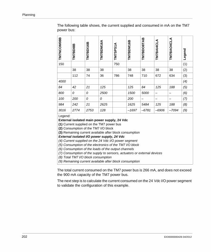
Planning
The following table shows, the current supplied and consumed in mA on the TM7 power bus:
The total current consumed on the TM7 power bus is 266 mA, and does not exceed the 900 mA capacity of the TM7 power bus.
The next step is to calculate the current consumed on the 24 Vdc I/O power segment to validate the configuration of this example.
TM
7NC
OM
08B
TM
7BD
I8B
TM
7BD
I16B
TM
7BD
M16
A
TM
7SP
S1A
TM
7BD
M16
B
TM
7BD
O8T
AB
TM
7BA
I4C
LA
TM
7BA
O4C
LA
Leg
end
150 750 (1)
38 38 38 38 38 38 38 (2)
112 74 36 786 748 710 672 634 (3)
4000 (4)
84 42 21 125 125 84 125 188 (5)
800 0 0 2500 1500 5000 – – (6)
100 200 0 0 200 – – – (7)
984 242 21 2625 1625 5484 125 188 (8)
3016 2774 2753 128 –1697 –6781 –6906 –7094 (9)
Legend:External isolated main power supply, 24 Vdc (1) Current supplied on the TM7 power bus(2) Consumption of the TM7 I/O block(3) Remaining current available after block consumptionExternal isolated I/O power supply, 24 Vdc (4) Current supplied on the 24 Vdc I/O power segment(5) Consumption of the electronics of the TM7 I/O block(6) Consumption of the loads of the output channels(7) Consumption of the supply to sensors, actuators or external devices(8) Total TM7 I/O block consumption(9) Remaining current available after block consumption
202 EIO0000000426 04/2012
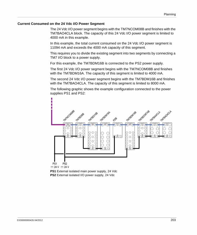
Planning
Current Consumed on the 24 Vdc I/O Power Segment
The 24 Vdc I/O power segment begins with the TM7NCOM08B and finishes with the TM7BAO4CLA block. The capacity of this 24 Vdc I/O power segment is limited to 4000 mA in this example.
In this example, the total current consumed on the 24 Vdc I/O power segment is 11094 mA and exceeds the 4000 mA capacity of this segment.
This requires you to divide the existing segment into two segments by connecting a TM7 I/O block to a power supply.
For this example, the TM7BDM16B is connected to the PS2 power supply.
The first 24 Vdc I/O power segment begins with the TM7NCOM08B and finishes with the TM7BDM16A. The capacity of this segment is limited to 4000 mA.
The second 24 Vdc I/O power segment begins with the TM7BDM16B and finishes with the TM7BAO4CLA. The capacity of this segment is limited to 8000 mA.
The following graphic shows the example configuration connected to the power supplies PS1 and PS2:
PS1 External isolated main power supply, 24 VdcPS2 External isolated I/O power supply, 24 Vdc
EIO0000000426 04/2012 203
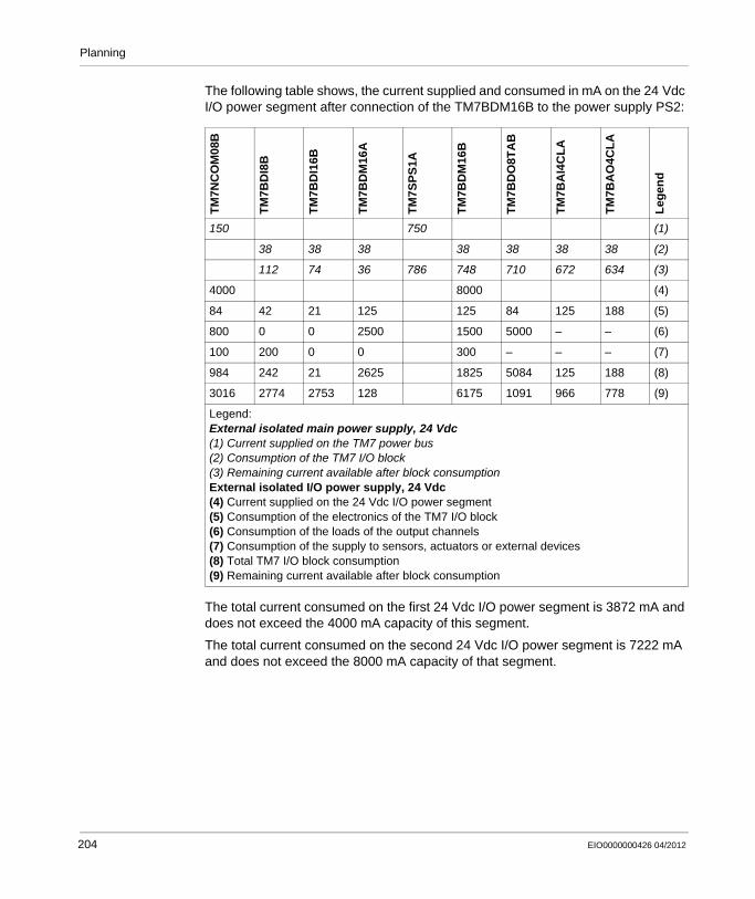
Planning
The following table shows, the current supplied and consumed in mA on the 24 Vdc I/O power segment after connection of the TM7BDM16B to the power supply PS2:
The total current consumed on the first 24 Vdc I/O power segment is 3872 mA and does not exceed the 4000 mA capacity of this segment.
The total current consumed on the second 24 Vdc I/O power segment is 7222 mA and does not exceed the 8000 mA capacity of that segment.
TM
7NC
OM
08B
TM
7BD
I8B
TM
7BD
I16B
TM
7BD
M16
A
TM
7SP
S1A
TM
7BD
M16
B
TM
7BD
O8T
AB
TM
7BA
I4C
LA
TM
7BA
O4C
LA
Leg
end
150 750 (1)
38 38 38 38 38 38 38 (2)
112 74 36 786 748 710 672 634 (3)
4000 8000 (4)
84 42 21 125 125 84 125 188 (5)
800 0 0 2500 1500 5000 – – (6)
100 200 0 0 300 – – – (7)
984 242 21 2625 1825 5084 125 188 (8)
3016 2774 2753 128 6175 1091 966 778 (9)
Legend:External isolated main power supply, 24 Vdc (1) Current supplied on the TM7 power bus(2) Consumption of the TM7 I/O block(3) Remaining current available after block consumptionExternal isolated I/O power supply, 24 Vdc (4) Current supplied on the 24 Vdc I/O power segment(5) Consumption of the electronics of the TM7 I/O block(6) Consumption of the loads of the output channels(7) Consumption of the supply to sensors, actuators or external devices(8) Total TM7 I/O block consumption(9) Remaining current available after block consumption
204 EIO0000000426 04/2012
Planning
Example 2: Current Consumed by a Remote Configuration
Introduction
This example is for a remote configuration (see page 20) (TM5 Transmitter module and TM7 expansion I/O blocks). From this example, you should be able to make the calculations necessary for your TM7 System.
All current consumption values are documented in the chapter Association and Power Consumption Tables (see page 241).
Planning Example
This configuration example includes:The TM5SBET7 transmitter module.Some expansion blocks:
TM7BDI8BTM7BDI16B (x3)TM7BDM16ATM7BDM16BTM7BDO8TABTM7BAI4CLATM7BAO4CLA
Assumptions used for the purposes of calculating the consumption of this example:TM7BDI8B: This block is connected to the power supply to distribute 8000 mA to
the 24 Vdc I/O power segment.The current to supply the electronic sensors of this example has been estimated at 25 mA per sensor, or 200 mA total for the block.
TM7BDI16B (x3): The current to supply the electronic sensors of this example has been estimated at 37.5 mA per sensor, or 500 mA total for the block.
TM7BDM16A: The sum of the current draw for all outputs connected to the block is never more than 2500 mA at any given time.The current to supply the electronic sensors of this example has been estimated at 12.5 mA per sensor, or 100 mA total for the block.
TM7BDM16B: The sum of the current draw for all outputs connected to the block is never more than 2000 mA at any given time.The current to supply the electronic sensors of this example has been estimated at 25 mA per sensor, or 200 mA total for the block.
TM7BDO8TAB: This block is connected to the power supply to distribute 8000 mA to the 24 Vdc I/O power segment.Only 6 of the outputs are active at any given time, and that the maximum current draw of any given output is 1000 mA, or 5000 mA total for the block.
EIO0000000426 04/2012 205

Planning
The following graphic shows the example configuration connected to the power supplies PS1 and PS2:
PS1 External isolated main power supply, 24 VdcPS2 External isolated I/O power supply, 24 Vdc
NOTE:
For important information concerning power supply connections (see page 217):TM5SBET7PDBI/O Block
206 EIO0000000426 04/2012
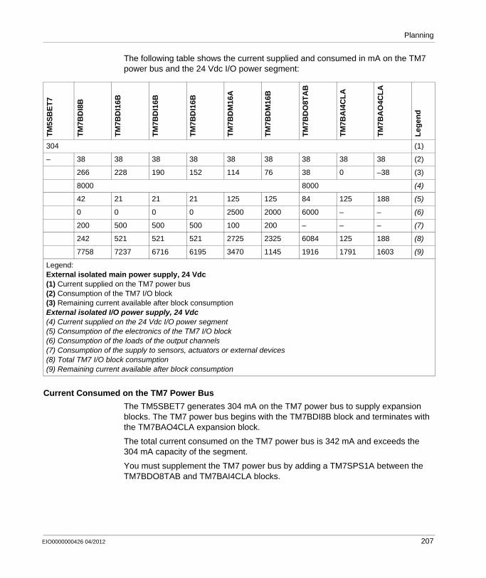
Planning
The following table shows the current supplied and consumed in mA on the TM7 power bus and the 24 Vdc I/O power segment:
Current Consumed on the TM7 Power Bus
The TM5SBET7 generates 304 mA on the TM7 power bus to supply expansion blocks. The TM7 power bus begins with the TM7BDI8B block and terminates with the TM7BAO4CLA expansion block.
The total current consumed on the TM7 power bus is 342 mA and exceeds the 304 mA capacity of the segment.
You must supplement the TM7 power bus by adding a TM7SPS1A between the TM7BDO8TAB and TM7BAI4CLA blocks.
TM
5SB
ET
7
TM
7BD
I8B
TM
7BD
I16B
TM
7BD
I16B
TM
7BD
I16B
TM
7BD
M16
A
TM
7BD
M16
B
TM
7BD
O8T
AB
TM
7BA
I4C
LA
TM
7BA
O4C
LA
Leg
end
304 (1)
– 38 38 38 38 38 38 38 38 38 (2)
266 228 190 152 114 76 38 0 –38 (3)
8000 8000 (4)
42 21 21 21 125 125 84 125 188 (5)
0 0 0 0 2500 2000 6000 – – (6)
200 500 500 500 100 200 – – – (7)
242 521 521 521 2725 2325 6084 125 188 (8)
7758 7237 6716 6195 3470 1145 1916 1791 1603 (9)
Legend:External isolated main power supply, 24 Vdc (1) Current supplied on the TM7 power bus(2) Consumption of the TM7 I/O block(3) Remaining current available after block consumptionExternal isolated I/O power supply, 24 Vdc (4) Current supplied on the 24 Vdc I/O power segment(5) Consumption of the electronics of the TM7 I/O block(6) Consumption of the loads of the output channels(7) Consumption of the supply to sensors, actuators or external devices(8) Total TM7 I/O block consumption(9) Remaining current available after block consumption
EIO0000000426 04/2012 207
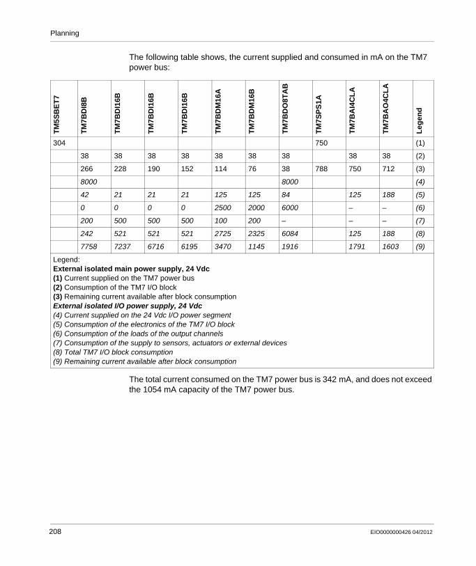
Planning
The following table shows, the current supplied and consumed in mA on the TM7 power bus:
The total current consumed on the TM7 power bus is 342 mA, and does not exceed the 1054 mA capacity of the TM7 power bus.
TM
5SB
ET
7
TM
7BD
I8B
TM
7BD
I16B
TM
7BD
I16B
TM
7BD
I16B
TM
7BD
M16
A
TM
7BD
M16
B
TM
7BD
O8T
AB
TM
7SP
S1A
TM
7BA
I4C
LA
TM
7BA
O4C
LA
Leg
end
304 750 (1)
38 38 38 38 38 38 38 38 38 (2)
266 228 190 152 114 76 38 788 750 712 (3)
8000 8000 (4)
42 21 21 21 125 125 84 125 188 (5)
0 0 0 0 2500 2000 6000 – – (6)
200 500 500 500 100 200 – – – (7)
242 521 521 521 2725 2325 6084 125 188 (8)
7758 7237 6716 6195 3470 1145 1916 1791 1603 (9)
Legend:External isolated main power supply, 24 Vdc (1) Current supplied on the TM7 power bus(2) Consumption of the TM7 I/O block(3) Remaining current available after block consumptionExternal isolated I/O power supply, 24 Vdc (4) Current supplied on the 24 Vdc I/O power segment(5) Consumption of the electronics of the TM7 I/O block(6) Consumption of the loads of the output channels(7) Consumption of the supply to sensors, actuators or external devices(8) Total TM7 I/O block consumption(9) Remaining current available after block consumption
208 EIO0000000426 04/2012

Planning
The following graphic shows the example configuration (with the PDB) connected to the power supplies PS1 and PS2:
PS1 External isolated main power supply, 24 VdcPS2 External isolated I/O power supply, 24 Vdc
For important information concerning power supply connections (see page 217):TM5SBET7PDBI/O Block
The next step is to calculate the current consumed on the 24 Vdc I/O power segment to validate the configuration of this example.
Current Consumed on the 24 Vdc I/O Power Segment
In this example,The first 24 Vdc I/O power segment begins with the TM7BDI8B and finishes with the TM7BDM16B. The capacity of this segment is limited to 8000 mA.The second 24 Vdc I/O power segment begins with the TM7BDO8TAB and finishes with the TM7BAO4CLA. The capacity of this segment is limited to 8000 mA.
EIO0000000426 04/2012 209
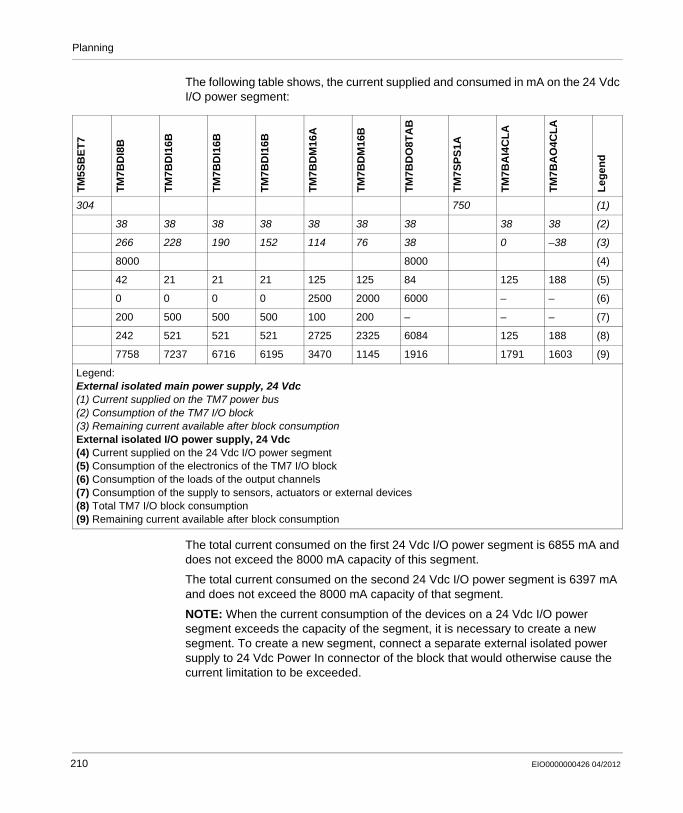
Planning
The following table shows, the current supplied and consumed in mA on the 24 Vdc I/O power segment:
The total current consumed on the first 24 Vdc I/O power segment is 6855 mA and does not exceed the 8000 mA capacity of this segment.
The total current consumed on the second 24 Vdc I/O power segment is 6397 mA and does not exceed the 8000 mA capacity of that segment.
NOTE: When the current consumption of the devices on a 24 Vdc I/O power segment exceeds the capacity of the segment, it is necessary to create a new segment. To create a new segment, connect a separate external isolated power supply to 24 Vdc Power In connector of the block that would otherwise cause the current limitation to be exceeded.
TM
5SB
ET
7
TM
7BD
I8B
TM
7BD
I16B
TM
7BD
I16B
TM
7BD
I16B
TM
7BD
M16
A
TM
7BD
M16
B
TM
7BD
O8T
AB
TM
7SP
S1A
TM
7BA
I4C
LA
TM
7BA
O4C
LA
Leg
end
304 750 (1)
38 38 38 38 38 38 38 38 38 (2)
266 228 190 152 114 76 38 0 –38 (3)
8000 8000 (4)
42 21 21 21 125 125 84 125 188 (5)
0 0 0 0 2500 2000 6000 – – (6)
200 500 500 500 100 200 – – – (7)
242 521 521 521 2725 2325 6084 125 188 (8)
7758 7237 6716 6195 3470 1145 1916 1791 1603 (9)
Legend:External isolated main power supply, 24 Vdc (1) Current supplied on the TM7 power bus(2) Consumption of the TM7 I/O block(3) Remaining current available after block consumptionExternal isolated I/O power supply, 24 Vdc (4) Current supplied on the 24 Vdc I/O power segment(5) Consumption of the electronics of the TM7 I/O block(6) Consumption of the loads of the output channels(7) Consumption of the supply to sensors, actuators or external devices(8) Total TM7 I/O block consumption(9) Remaining current available after block consumption
210 EIO0000000426 04/2012
Planning
7.4 Electrical Requirements
Introduction
The following section provides the general wiring rules and recommendations for the TM7 System. Considerations and techniques for grounding the TM7 System are also presented.
What’s in this Section?
This section contains the following topics:
Topic Page
Wiring Rules and Recommendations 212
Selecting an External 24 Vdc Power Supply 216
Wiring the Power Supply 217
EIO0000000426 04/2012 211
Planning
Wiring Rules and Recommendations
Introduction
There are several rules that must be followed when wiring a TM7 System. Refer to TM7 Cables (see page 337) for additional details.
Wiring Rules
The following rules must be applied when wiring the TM7 System:I/O and communication wiring must be kept separate from the power wiring. Route these 2 types of wiring in separate cable ducting.Verify that the operating conditions and environment are within the specification values.Use proper wire sizes to meet voltage and current requirements.Use copper conductors only.Use only the TM7 expansion bus cables (see page 338).
DANGERHAZARD OF ELECTRIC SHOCK, EXPLOSION OR ARC FLASH
Disconnect all power from all equipment including connected devices prior to removing any covers or doors, or installing or removing any accessories, hardware, cables, or wires except under the specific conditions specified in the appropriate hardware guide for this equipment.Always use a properly rated voltage sensing device to confirm the power is off where and when indicated.Replace and secure all covers, accessories, hardware, cables, and wires and confirm that a proper ground connection exists before applying power to the unit.Use only the specified voltage when operating this equipment and any associated products.
Failure to follow these instructions will result in death or serious injury.
212 EIO0000000426 04/2012
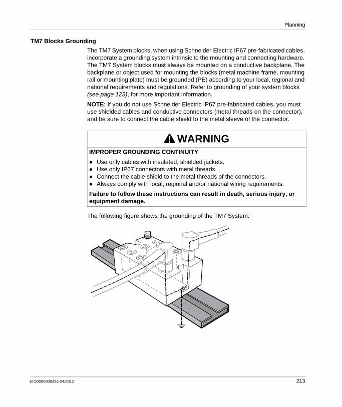
Planning
TM7 Blocks Grounding
The TM7 System blocks, when using Schneider Electric IP67 pre-fabricated cables, incorporate a grounding system intrinsic to the mounting and connecting hardware. The TM7 System blocks must always be mounted on a conductive backplane. The backplane or object used for mounting the blocks (metal machine frame, mounting rail or mounting plate) must be grounded (PE) according to your local, regional and national requirements and regulations. Refer to grounding of your system blocks (see page 123), for more important information.
NOTE: If you do not use Schneider Electric IP67 pre-fabricated cables, you must use shielded cables and conductive connectors (metal threads on the connector), and be sure to connect the cable shield to the metal sleeve of the connector.
The following figure shows the grounding of the TM7 System:
WARNINGIMPROPER GROUNDING CONTINUITY
Use only cables with insulated, shielded jackets.Use only IP67 connectors with metal threads.Connect the cable shield to the metal threads of the connectors.Always comply with local, regional and/or national wiring requirements.
Failure to follow these instructions can result in death, serious injury, or equipment damage.
t
EIO0000000426 04/2012 213
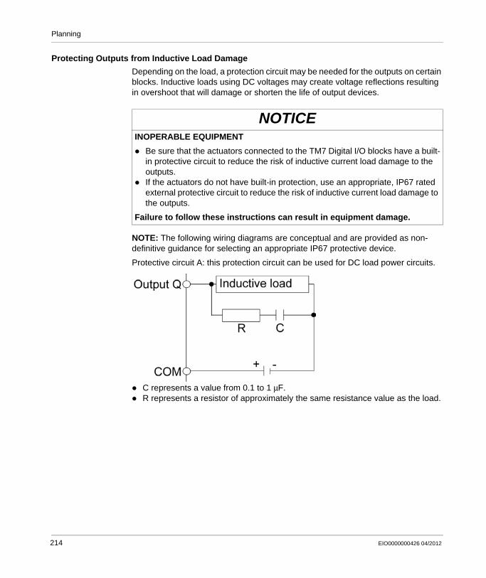
Planning
Protecting Outputs from Inductive Load Damage
Depending on the load, a protection circuit may be needed for the outputs on certain blocks. Inductive loads using DC voltages may create voltage reflections resulting in overshoot that will damage or shorten the life of output devices.
NOTE: The following wiring diagrams are conceptual and are provided as non-definitive guidance for selecting an appropriate IP67 protective device.
Protective circuit A: this protection circuit can be used for DC load power circuits.
C represents a value from 0.1 to 1 μF.R represents a resistor of approximately the same resistance value as the load.
NOTICEINOPERABLE EQUIPMENT
Be sure that the actuators connected to the TM7 Digital I/O blocks have a built-in protective circuit to reduce the risk of inductive current load damage to the outputs.If the actuators do not have built-in protection, use an appropriate, IP67 rated external protective circuit to reduce the risk of inductive current load damage to the outputs.
Failure to follow these instructions can result in equipment damage.
214 EIO0000000426 04/2012
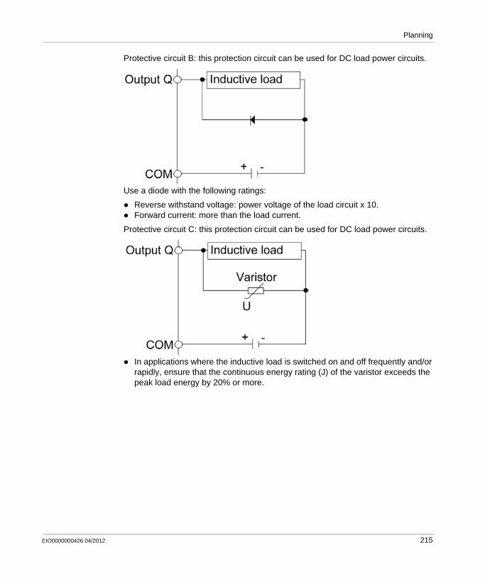
Planning
Protective circuit B: this protection circuit can be used for DC load power circuits.
Use a diode with the following ratings:
Reverse withstand voltage: power voltage of the load circuit x 10.Forward current: more than the load current.
Protective circuit C: this protection circuit can be used for DC load power circuits.
In applications where the inductive load is switched on and off frequently and/or rapidly, ensure that the continuous energy rating (J) of the varistor exceeds the peak load energy by 20% or more.
EIO0000000426 04/2012 215

Planning
Selecting an External 24 Vdc Power Supply
Characteristics of the 24 Vdc Power Supply
The TM7 System requires power supplies with a nominal voltage of 24 Vdc. The 24 Vdc power supplies must be rated Safety Extra Low Voltage (SELV) or Protective Extra Low Voltage (PELV) according to IEC 61140. These power supplies are isolated between the electrical input and output circuits of the power supply.
Calculating the Power Supply Requirement
Refer to Power Distribution System Design (see page 198).
WARNINGPOTENTIAL OF OVERHEATING AND FIRE
Do not connect the modules directly to line voltage.Use only isolating PELV or SELV power supplies to supply power to the modules.
Failure to follow these instructions can result in death, serious injury, or equipment damage.
216 EIO0000000426 04/2012
Planning
Wiring the Power Supply
Overview
To distribute current for the 24 Vdc I/O power segment(s) and TM7 power bus, and according to the power distribution description (see page 193), the following modules and blocks are connected to an external power source:
Transmitter module (TM5SBET7)Field bus interface I/O blockPower Distribution Block (PDB)I/O blocks
Source power for these can come from one or more supplies. Your requirements are dictated by:
voltage and current needsisolation requirements
Wiring the Transmitter Module (TM5SBET7)
The TM5SBET7 (see page 195) is the connection to the external 24 Vdc power supply and the beginning of the power distribution for the TM7 remote configuration. The power is supplied by one external isolated power supply depending on current needs and capabilities.
WARNINGPOTENTIAL OF OVERHEATING AND FIRE
Do not connect the modules directly to line voltage.Use only isolating PELV or SELV power supplies to supply power to the modules.
Failure to follow these instructions can result in death, serious injury, or equipment damage.
EIO0000000426 04/2012 217
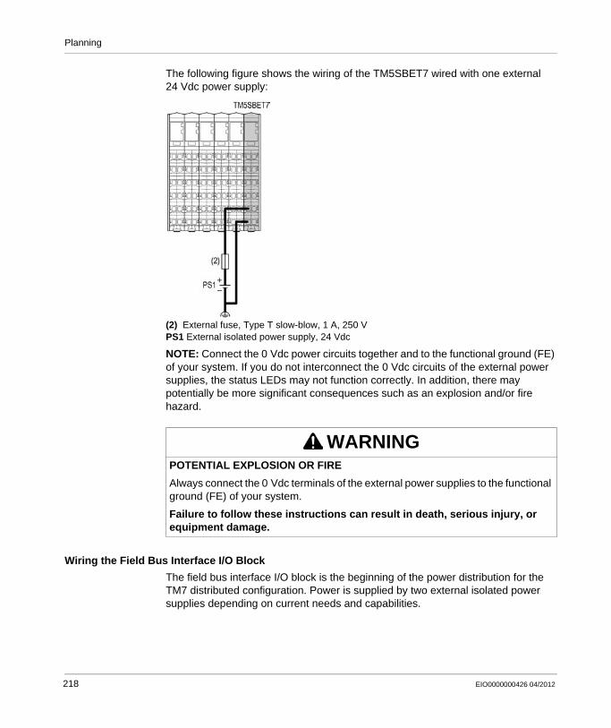
Planning
The following figure shows the wiring of the TM5SBET7 wired with one external 24 Vdc power supply:
(2) External fuse, Type T slow-blow, 1 A, 250 VPS1 External isolated power supply, 24 Vdc
NOTE: Connect the 0 Vdc power circuits together and to the functional ground (FE) of your system. If you do not interconnect the 0 Vdc circuits of the external power supplies, the status LEDs may not function correctly. In addition, there may potentially be more significant consequences such as an explosion and/or fire hazard.
Wiring the Field Bus Interface I/O Block
The field bus interface I/O block is the beginning of the power distribution for the TM7 distributed configuration. Power is supplied by two external isolated power supplies depending on current needs and capabilities.
WARNINGPOTENTIAL EXPLOSION OR FIRE
Always connect the 0 Vdc terminals of the external power supplies to the functional ground (FE) of your system.
Failure to follow these instructions can result in death, serious injury, or equipment damage.
218 EIO0000000426 04/2012
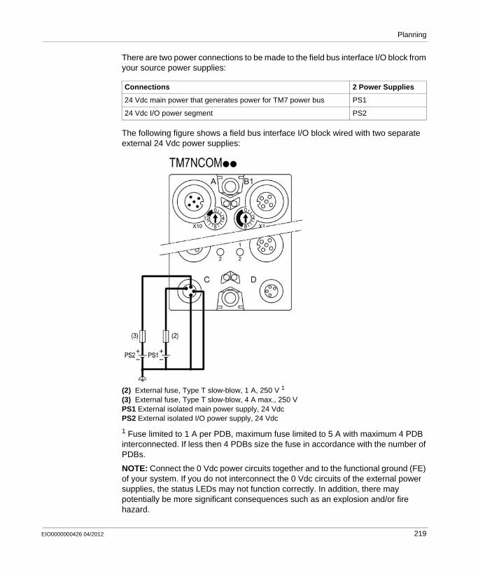
Planning
There are two power connections to be made to the field bus interface I/O block from your source power supplies:
The following figure shows a field bus interface I/O block wired with two separate external 24 Vdc power supplies:
(2) External fuse, Type T slow-blow, 1 A, 250 V 1
(3) External fuse, Type T slow-blow, 4 A max., 250 VPS1 External isolated main power supply, 24 VdcPS2 External isolated I/O power supply, 24 Vdc
1 Fuse limited to 1 A per PDB, maximum fuse limited to 5 A with maximum 4 PDB interconnected. If less then 4 PDBs size the fuse in accordance with the number of PDBs.
NOTE: Connect the 0 Vdc power circuits together and to the functional ground (FE) of your system. If you do not interconnect the 0 Vdc circuits of the external power supplies, the status LEDs may not function correctly. In addition, there may potentially be more significant consequences such as an explosion and/or fire hazard.
Connections 2 Power Supplies
24 Vdc main power that generates power for TM7 power bus PS1
24 Vdc I/O power segment PS2
EIO0000000426 04/2012 219
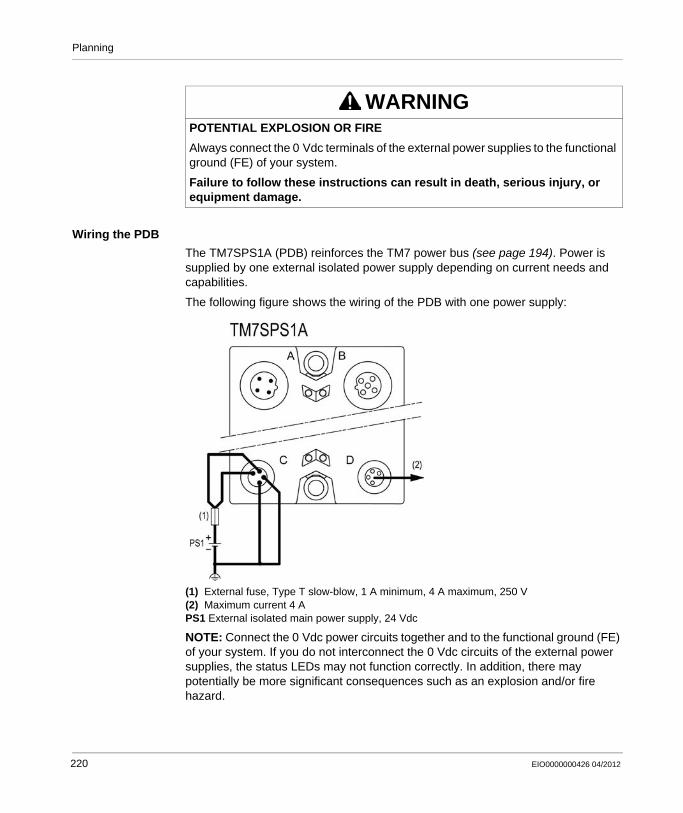
Planning
Wiring the PDB
The TM7SPS1A (PDB) reinforces the TM7 power bus (see page 194). Power is supplied by one external isolated power supply depending on current needs and capabilities.
The following figure shows the wiring of the PDB with one power supply:
(1) External fuse, Type T slow-blow, 1 A minimum, 4 A maximum, 250 V(2) Maximum current 4 APS1 External isolated main power supply, 24 Vdc
NOTE: Connect the 0 Vdc power circuits together and to the functional ground (FE) of your system. If you do not interconnect the 0 Vdc circuits of the external power supplies, the status LEDs may not function correctly. In addition, there may potentially be more significant consequences such as an explosion and/or fire hazard.
WARNINGPOTENTIAL EXPLOSION OR FIRE
Always connect the 0 Vdc terminals of the external power supplies to the functional ground (FE) of your system.
Failure to follow these instructions can result in death, serious injury, or equipment damage.
220 EIO0000000426 04/2012
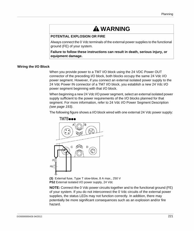
Planning
Wiring the I/O Block
When you provide power to a TM7 I/O block using the 24 VDC Power OUT connector of the preceding I/O block, both blocks occupy the same 24 Vdc I/O power segment. However, if you connect an external isolated power supply to the 24 Vdc Power IN connector of a TM7 I/O block, you establish a new 24 Vdc I/O power segment beginning with that I/O block.
When beginning a new 24 Vdc I/O power segment, select an external isolated power supply sufficient to the power requirements of the I/O blocks planned for that segment. For more information, refer to 24 Vdc I/O Power Segment Description (see page 193).
The following figure shows a I/O block wired with one external 24 Vdc power supply:
(3) External fuse, Type T slow-blow, 8 A max., 250 VPS2 External isolated I/O power supply, 24 Vdc
NOTE: Connect the 0 Vdc power circuits together and to the functional ground (FE) of your system. If you do not interconnect the 0 Vdc circuits of the external power supplies, the status LEDs may not function correctly. In addition, there may potentially be more significant consequences such as an explosion and/or fire hazard.
WARNINGPOTENTIAL EXPLOSION OR FIRE
Always connect the 0 Vdc terminals of the external power supplies to the functional ground (FE) of your system.
Failure to follow these instructions can result in death, serious injury, or equipment damage.
EIO0000000426 04/2012 221

Planning
WARNINGPOTENTIAL EXPLOSION OR FIRE
Always connect the 0 Vdc terminals of the external power supplies to the functional ground (FE) of your system.
Failure to follow these instructions can result in death, serious injury, or equipment damage.
222 EIO0000000426 04/2012
EIO0000000426 04/2012
8
Modicon TM5 / TM7 Flexible System
Installation procedures
EIO0000000426 04/2012
Installation Procedures
Overview
This chapter focuses on procedures for construction of a TM7 System. The installation guidelines summarize the steps involved in the installation process.
What’s in this Chapter?
This chapter contains the following topics:
Topic Page
Installation Requirements 224
Installation Guidelines 227
Addressing 235
223

Installation procedures
Installation Requirements
Before Starting
Read and understand this chapter before beginning the installation of your TM7 System.
DANGEREXPLOSIVE POTENTIAL
Use devices with explosion protection as intended according to these operation instructions and corresponding documents.Only permit knowledgeable and qualified personnel to install, maintain and/or operate these devices.Conform to valid safety and accident prevention regulations and adhere to standards such as IEC/EN 60079-14.Be sure that all other associated equipment, such as cables and connectors, are also suitable for the operating location.Ground all devices, using a metal plate, terminal strip or mounting plate securely connected to the housing back plate, to an equalized potential.Remove all power from all equipment before installing or removing devices (including other connected devices), accessories, hardware, cables, or wires.Devices must remain voltage free until all installation or maintenance work is completed.Remove as necessary dust collecting on devices that can cause explosions.Be sure that all connectors and sealing plugs on the M8 and M12 connectors are in place and fastened with a torque between 0.2 and 0.4 N.m (1.8 and 3.5 lbf-in) before applying any power.Be sure that all connectors are firmly sealed with either properly wired connectors or sealing plugs before applying power during regular operation.
Failure to follow these instructions will result in death or serious injury.
NOTICEELECTROSTATIC DISCHARGE
Never touch the pin connectors of the block.Always keep the cables or sealing plugs in place during normal operation.
Failure to follow these instructions can result in equipment damage.
224 EIO0000000426 04/2012

Installation procedures
Programming Considerations
Operating Environment
NOTE: Additional equipment used in conjunction with the equipment described herein must also be suitable for the operating location.
Requirements for use in ATEX Group II, Zone 2:Install and use the equipment strictly in accordance to the installation and operating instructions found here and in other related documentation.Respect and follow all valid safety and accident prevention regulations, as well as adhering to standards such as IEC/EN 60079-14 or those that govern the eventual locality of your application.All equipment must be grounded to an equipotential ground plane dimensioned to the power system of your application.Equipment must remain unpowered until installation work is completed, including all cable connections with the proper torque having been applied to all connector unions.Before applying power, be sure that all connectors that are not being used (open connectors with no cable attached) are capped with suitable sealing plugs.
WARNINGUNINTENDED EQUIPMENT OPERATION
Only use software approved by Schneider Electric for use with this equipment.Update your application program every time you change the physical hardware configuration.
Failure to follow these instructions can result in death, serious injury, or equipment damage.
DANGEREXPLOSIVE POTENTIAL
Only use this equipment in non-hazardous locations or in locations that comply either with the Class I, Division 2, Groups A, B, C and D, or with the ATEX Group II, Zone 2 specifications for hazardous locations, depending on your local and/or national regulations.Do not substitute components which would impair compliance to the hazardous location specifications of this equipment.Do not connect or disconnect equipment unless power has been removed or the area is known to be non-hazardous.
Failure to follow these instructions will result in death or serious injury.
EIO0000000426 04/2012 225
Installation procedures
During service or maintenance, the equipment must be shut down and protected from being accidently restarted.Do not connect or disconnect cables or sealing plugs under power unless the equipment is in a known non-hazardous location.
Installation Considerations
NOTE: Schneider Electric recommends the use of UL-recognized and CSA approved JDYX2 or JDYX8 fuse types.
WARNINGUNINTENDED EQUIPMENT OPERATION
Install and operate this equipment according to the environmental conditions described in the operating limits.
Failure to follow these instructions can result in death, serious injury, or equipment damage.
WARNINGUNINTENDED EQUIPMENT OPERATION
Use appropriate safety interlocks where personnel and/or equipment hazards exist.Use the sensor and actuator power supplies only for supplying power to the sensors or actuators connected to the module.Power line and output circuits must be wired and fused in compliance with local and national regulatory requirements for the rated current and voltage of the particular equipment.Do not use this equipment in safety-critical machine functions.Do not disassemble, repair, or modify this equipment.Do not connect any wiring to unused connections, or to connections designated as Not Connected (N.C.).
Failure to follow these instructions can result in death, serious injury, or equipment damage.
226 EIO0000000426 04/2012

Installation procedures
Installation Guidelines
Introduction
The TM7 System can be mounted using:An aluminium frame with two wedge nuts and M4 screwsA DIN rail with TM7ACMP mounting plateDirectly on the machine.
NOTE: Mounting on a DIN rail using the TM7ACMP mounting plate is only possible with the size 1 (smallest) block dimension (see page 189).
NOTE: The TM7 System components must always be mounted to a conductive backplane.
TM7 Block on an Aluminium Frame
Blocks can be mounted on an aluminium frame with two wedge nuts and M4 screws:
NOTE: Maximum torque to fasten the M4 screws is 0.6 N.m (5.3 lbf-in).
TM7 Block on a DIN Rail
You can mount the size 1 blocks on a DIN rail with the TM7ACMP (see page 60) mounting plate. For EMC (Electromagnetic Compatibility) compliance, a metal DIN rail must be attached to a flat metal mounting surface or mounted on an EIA (Electronic Industries Alliance) rack or in a NEMA (National Electrical Manufacturers Association) enclosure. In all cases, the mounting surface must be properly grounded (see page 123).
NOTICEINOPERABLE EQUIPMENT
Ensure that the block is securely affixed to its mounting surface.Do not tighten screws beyond the specified maximum torque.
Failure to follow these instructions can result in equipment damage.
M4
M4
M4
EIO0000000426 04/2012 227
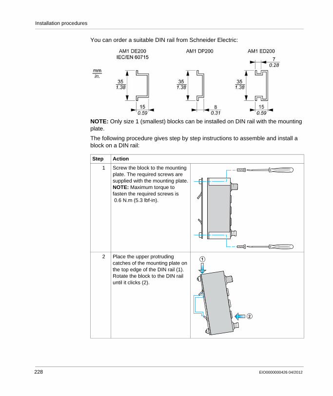
Installation procedures
You can order a suitable DIN rail from Schneider Electric:
NOTE: Only size 1 (smallest) blocks can be installed on DIN rail with the mounting plate.
The following procedure gives step by step instructions to assemble and install a block on a DIN rail:
Step Action
1 Screw the block to the mounting plate. The required screws are supplied with the mounting plate.NOTE: Maximum torque to fasten the required screws is 0.6 N.m (5.3 lbf-in).
2 Place the upper protruding catches of the mounting plate on the top edge of the DIN rail (1).Rotate the block to the DIN rail until it clicks (2).
2
1
228 EIO0000000426 04/2012
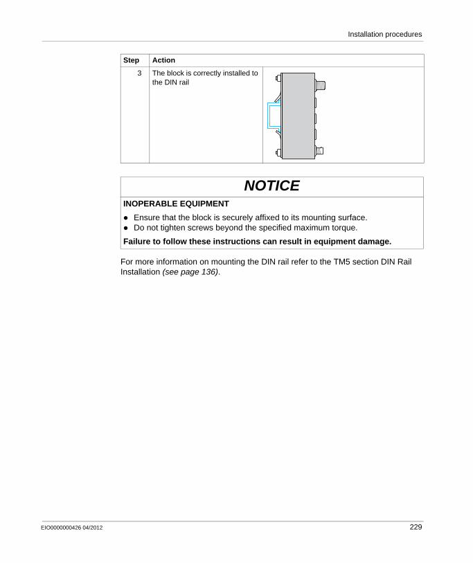
Installation procedures
For more information on mounting the DIN rail refer to the TM5 section DIN Rail Installation (see page 136).
3 The block is correctly installed to the DIN rail
NOTICEINOPERABLE EQUIPMENT
Ensure that the block is securely affixed to its mounting surface.Do not tighten screws beyond the specified maximum torque.
Failure to follow these instructions can result in equipment damage.
Step Action
EIO0000000426 04/2012 229
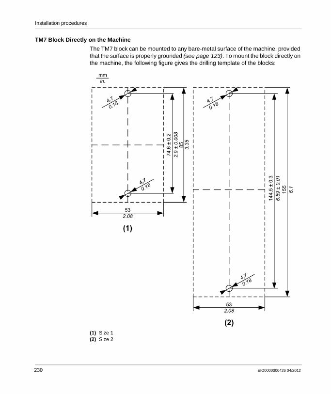
Installation procedures
TM7 Block Directly on the Machine
The TM7 block can be mounted to any bare-metal surface of the machine, provided that the surface is properly grounded (see page 123). To mount the block directly on the machine, the following figure gives the drilling template of the blocks:
(1) Size 1(2) Size 2
230 EIO0000000426 04/2012
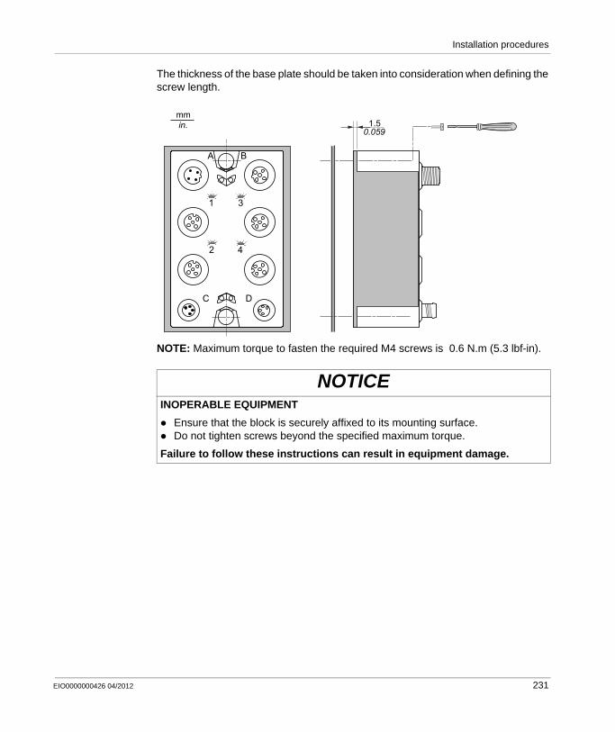
Installation procedures
The thickness of the base plate should be taken into consideration when defining the screw length.
NOTE: Maximum torque to fasten the required M4 screws is 0.6 N.m (5.3 lbf-in).
NOTICEINOPERABLE EQUIPMENT
Ensure that the block is securely affixed to its mounting surface.Do not tighten screws beyond the specified maximum torque.
Failure to follow these instructions can result in equipment damage.
mm in. 1.5
0.059
A B
C D
1
2
3
4
EIO0000000426 04/2012 231
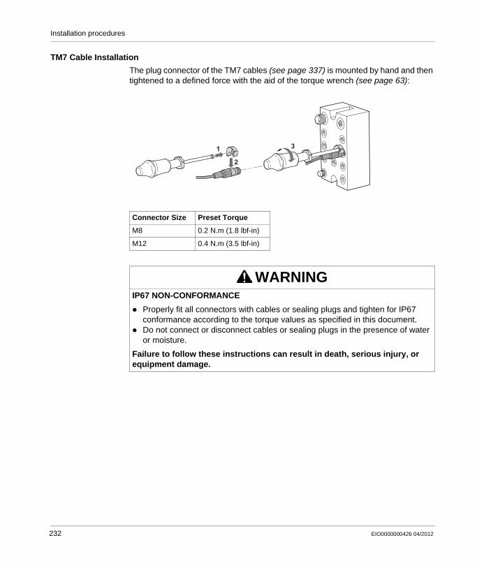
Installation procedures
TM7 Cable Installation
The plug connector of the TM7 cables (see page 337) is mounted by hand and then tightened to a defined force with the aid of the torque wrench (see page 63):
Connector Size Preset Torque
M8 0.2 N.m (1.8 lbf-in)
M12 0.4 N.m (3.5 lbf-in)
WARNINGIP67 NON-CONFORMANCE
Properly fit all connectors with cables or sealing plugs and tighten for IP67 conformance according to the torque values as specified in this document.Do not connect or disconnect cables or sealing plugs in the presence of water or moisture.
Failure to follow these instructions can result in death, serious injury, or equipment damage.
1
2
3
232 EIO0000000426 04/2012
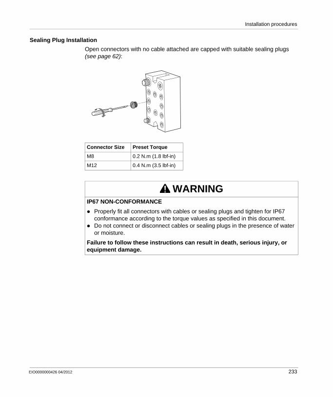
Installation procedures
Sealing Plug Installation
Open connectors with no cable attached are capped with suitable sealing plugs (see page 62):
Connector Size Preset Torque
M8 0.2 N.m (1.8 lbf-in)
M12 0.4 N.m (3.5 lbf-in)
WARNINGIP67 NON-CONFORMANCE
Properly fit all connectors with cables or sealing plugs and tighten for IP67 conformance according to the torque values as specified in this document.Do not connect or disconnect cables or sealing plugs in the presence of water or moisture.
Failure to follow these instructions can result in death, serious injury, or equipment damage.
EIO0000000426 04/2012 233
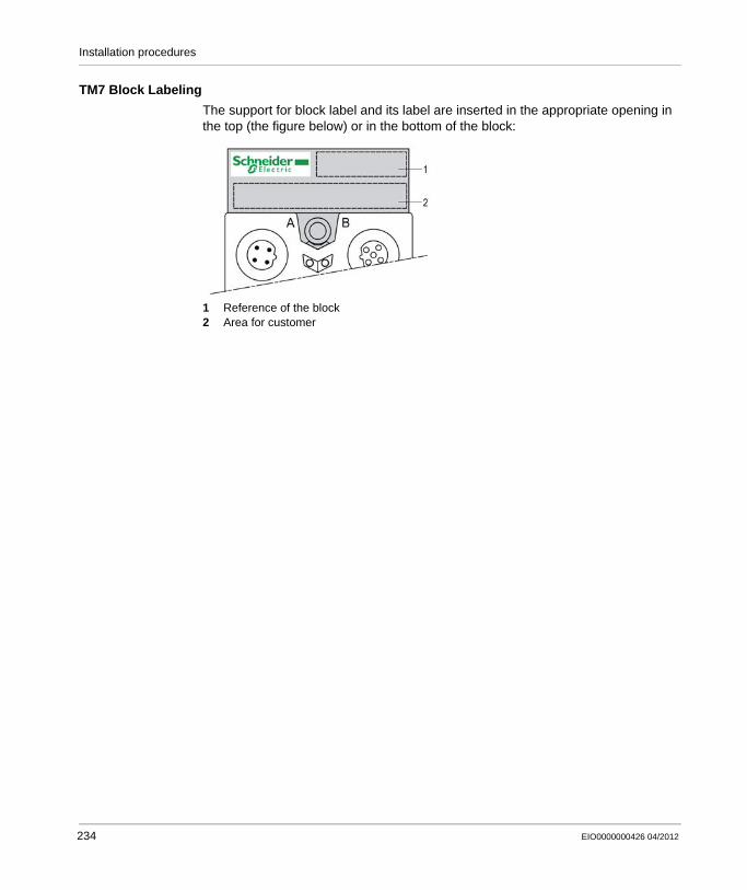
Installation procedures
TM7 Block Labeling
The support for block label and its label are inserted in the appropriate opening in the top (the figure below) or in the bottom of the block:
1 Reference of the block2 Area for customer
234 EIO0000000426 04/2012

Installation procedures
Addressing
Addressing Principle
The TM7 bus is self-addressing, and automatically increments by 1 starting with the first I/O block after the TM5SBET7 transmitter module. For example, if the address of the transmitter module is 10, the first TM7 I/O block will automatically be assigned an address of 11.
NOTE: The TM7 Power Distribution Block (PDB) does not have a physical address.
An Example of Addressing
The example below illustrates the addressing principle for the TM7 bus. As you can see, the TM7 System automatically addresses the I/O blocks from left to right:
TM7NCOM•• TM7 Field bus interface I/O blockTM5SBET7 Transmitter modulePDB Power Distribution Block
EIO0000000426 04/2012 235

Installation procedures
236 EIO0000000426 04/2012
EIO0000000426 04/2012
9
Modicon TM5 / TM7 Flexible System
Commissioning and Maintaining
EIO0000000426 04/2012
Commissioning and Maintaining
Diagnostics
Diagnostics
The TM7 System offer several levels of diagnostics depending on master architecture on the block using visual LED displays.
Refer to the hardware guides for the products of the TM7 System for status LEDs descriptions.
237

Commissioning and Maintaining
238 EIO0000000426 04/2012
Modicon TM5 / TM7 Flexible System
EIO0000000426 04/2012
Appendices
Overview
These appendices give the association and power consumption tables, the description of the power distribution and common distribution electronic modules, the bus bases and terminal blocks for designing your TM5 System.
What’s in this Appendix?
The appendix contains the following chapters:
Chapter Chapter Name Page
A Association and Power Consumption Tables 241
B TM5 Power Distribution Modules (PDM) 259
C TM5 Common Distribution Modules (CDM) 289
D TM5 Accessories Modules 319
E TM5 Bus Bases and Terminal Blocks 321
F TM7 Power Distribution Block (PDB) 329
G TM7 Cables 337
EIO0000000426 04/2012 239

240 EIO0000000426 04/2012
EIO0000000426 04/2012
A
Modicon TM5 / TM7 Flexible System
Association and Power Consumption Tables
EIO0000000426 04/2012
Association and Power Consumption Tables
Overview
This chapter gives the association table and power consumption tables that are useful for designing your TM5 System and TM7 System.
What’s in this Chapter?
This chapter contains the following sections:
Section Topic Page
A.1 Association Table 242
A.2 TM5 Power Consumption Tables 245
A.3 TM7 Power Consumption Tables 254
241
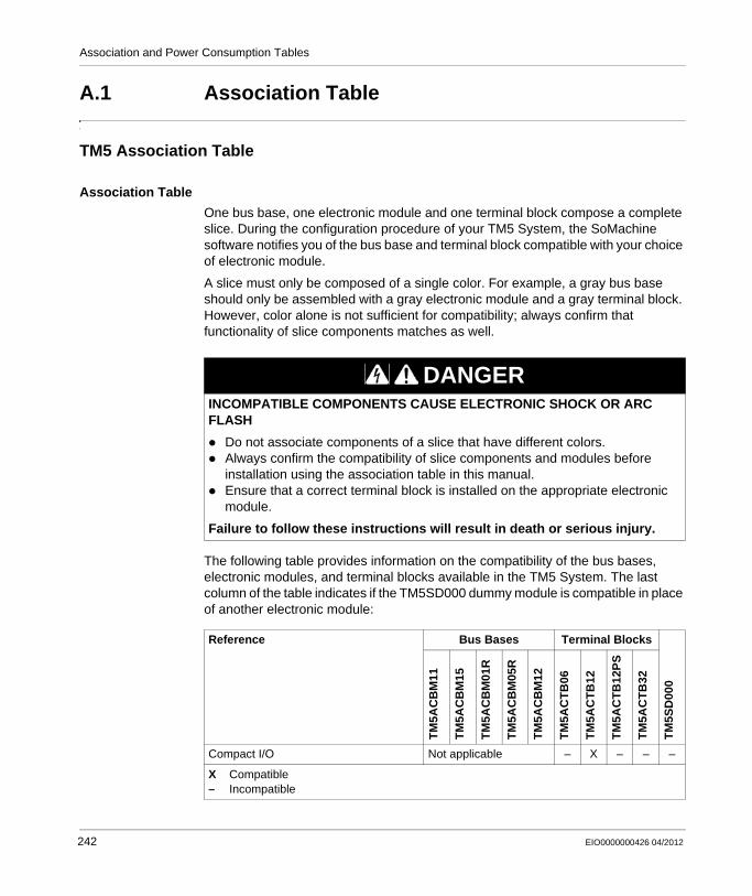
Association and Power Consumption Tables
A.1 Association Table
TM5 Association Table
Association Table
One bus base, one electronic module and one terminal block compose a complete slice. During the configuration procedure of your TM5 System, the SoMachine software notifies you of the bus base and terminal block compatible with your choice of electronic module.
A slice must only be composed of a single color. For example, a gray bus base should only be assembled with a gray electronic module and a gray terminal block. However, color alone is not sufficient for compatibility; always confirm that functionality of slice components matches as well.
The following table provides information on the compatibility of the bus bases, electronic modules, and terminal blocks available in the TM5 System. The last column of the table indicates if the TM5SD000 dummy module is compatible in place of another electronic module:
DANGERINCOMPATIBLE COMPONENTS CAUSE ELECTRONIC SHOCK OR ARC FLASH
Do not associate components of a slice that have different colors.Always confirm the compatibility of slice components and modules before installation using the association table in this manual.Ensure that a correct terminal block is installed on the appropriate electronic module.
Failure to follow these instructions will result in death or serious injury.
Reference Bus Bases Terminal Blocks
TM
5SD
000
TM
5AC
BM
11
TM
5AC
BM
15
TM
5AC
BM
01R
TM
5AC
BM
05R
TM
5AC
BM
12
TM
5AC
TB
06
TM
5AC
TB
12
TM
5AC
TB
12P
S
TM
5AC
TB
32
Compact I/O Not applicable – X – – –
X Compatible– Incompatible
242 EIO0000000426 04/2012
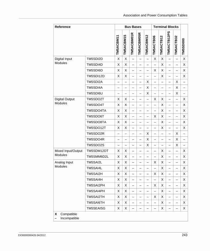
Association and Power Consumption Tables
Digital Input Modules
TM5SDI2D X X – – – X X – – X
TM5SDI4D X X – – – – X – – X
TM5SDI6D X X – – – X X – – X
TM5SDI12D X X – – – – X – – X
TM5SDI2A – – – – X – – – X –
TM5SDI4A – – – – X – – – X –
TM5SDI6U – – – – X – – – X –
Digital Output Modules
TM5SDO2T X X – – – X X – – X
TM5SDO4T X X – – – – X – – X
TM5SDO4TA X X – – – – X – – X
TM5SDO6T X X – – – X X – – X
TM5SDO8TA X X – – – – X – – X
TM5SDO12T X X – – – – X – – X
TM5SDO2R – – – – X – – – X –
TM5SDO4R – – – – X – – – X –
TM5SDO2S – – – – X – – – X –
Mixed Input/Output Modules
TM5SDM12DT X X – – – – X – – X
TM5SMM6D2L X X – – – – X – – X
Analog Input Modules
TM5SAI2L X X – – – X X – – X
TM5SAI4L X X – – – – X – – X
TM5SAI2H X X – – – X X – – X
TM5SAI4H X X – – – – X – – X
TM5SAI2PH X X – – – X X – – X
TM5SAI4PH X X – – – – X – – X
TM5SAI2TH X X – – – X X – – X
TM5SAI6TH X X – – – – X – – X
TM5SEAISG X X – – – – X – – X
Reference Bus Bases Terminal Blocks
TM
5SD
000
TM
5AC
BM
11
TM
5AC
BM
15
TM
5AC
BM
01R
TM
5AC
BM
05R
TM
5AC
BM
12
TM
5AC
TB
06
TM
5AC
TB
12
TM
5AC
TB
12P
S
TM
5AC
TB
32
X Compatible– Incompatible
EIO0000000426 04/2012 243
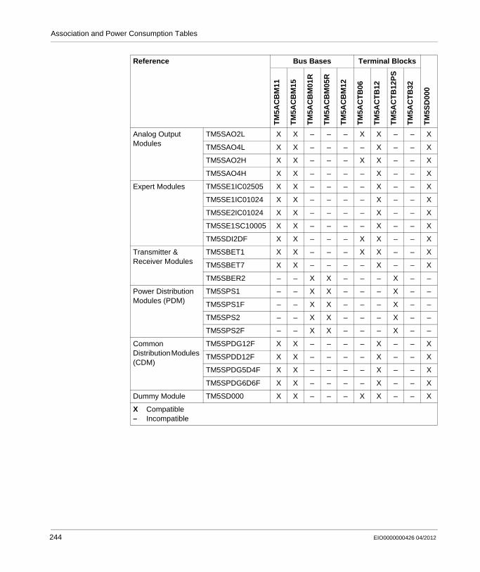
Association and Power Consumption Tables
Analog Output Modules
TM5SAO2L X X – – – X X – – X
TM5SAO4L X X – – – – X – – X
TM5SAO2H X X – – – X X – – X
TM5SAO4H X X – – – – X – – X
Expert Modules TM5SE1IC02505 X X – – – – X – – X
TM5SE1IC01024 X X – – – – X – – X
TM5SE2IC01024 X X – – – – X – – X
TM5SE1SC10005 X X – – – – X – – X
TM5SDI2DF X X – – – X X – – X
Transmitter & Receiver Modules
TM5SBET1 X X – – – X X – – X
TM5SBET7 X X – – – – X – – X
TM5SBER2 – – X X – – – X – –
Power Distribution Modules (PDM)
TM5SPS1 – – X X – – – X – –
TM5SPS1F – – X X – – – X – –
TM5SPS2 – – X X – – – X – –
TM5SPS2F – – X X – – – X – –
Common Distribution Modules (CDM)
TM5SPDG12F X X – – – – X – – X
TM5SPDD12F X X – – – – X – – X
TM5SPDG5D4F X X – – – – X – – X
TM5SPDG6D6F X X – – – – X – – X
Dummy Module TM5SD000 X X – – – X X – – X
Reference Bus Bases Terminal Blocks
TM
5SD
000
TM
5AC
BM
11
TM
5AC
BM
15
TM
5AC
BM
01R
TM
5AC
BM
05R
TM
5AC
BM
12
TM
5AC
TB
06
TM
5AC
TB
12
TM
5AC
TB
12P
S
TM
5AC
TB
32X Compatible– Incompatible
244 EIO0000000426 04/2012

Association and Power Consumption Tables
A.2 TM5 Power Consumption Tables
Introduction
This section gives the current supplied and consumption tables useful for designing your TM5 System.
What’s in this Section?
This section contains the following topics:
Topic Page
Current Supplied and Consumption Tables on the 24 Vdc I/O Power Segment 246
Current Supplied and Consumption Tables on the TM5 Power Bus 250
EIO0000000426 04/2012 245
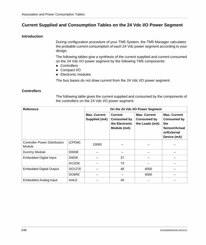
Association and Power Consumption Tables
Current Supplied and Consumption Tables on the 24 Vdc I/O Power Segment
Introduction
During configuration procedure of your TM5 System, the TM5 Manager calculates the probable current consumption of each 24 Vdc power segment according to your design.
The following tables give a synthesis of the current supplied and current consumed on the 24 Vdc I/O power segment by the following TM5 components:
ControllersCompact I/OElectronic modules
The bus bases do not draw current from the 24 Vdc I/O power segment.
Controllers
The following table gives the current supplied and consumed by the components of the controllers on the 24 Vdc I/O power segment:
Reference On the 24 Vdc I/O Power Segment
Max. Current Supplied (mA)
Current Consumed by the Electronic Module (mA)
Max. Current Consumed by the Loads (mA)
Max. Current Consumed by the Sensor/Actuator/External Device (mA)
Controller Power Distribution Module
(CPDM)10000 – – –
Dummy Module D000E – – – –
Embedded Digital Input DI6DE – 37 – –
DI12DE – 73 – –
Embedded Digital Output DO12TE – 48 6000 –
DO6RE – – 6000 –
Embedded Analog Input AI4LE – 46 – –
246 EIO0000000426 04/2012
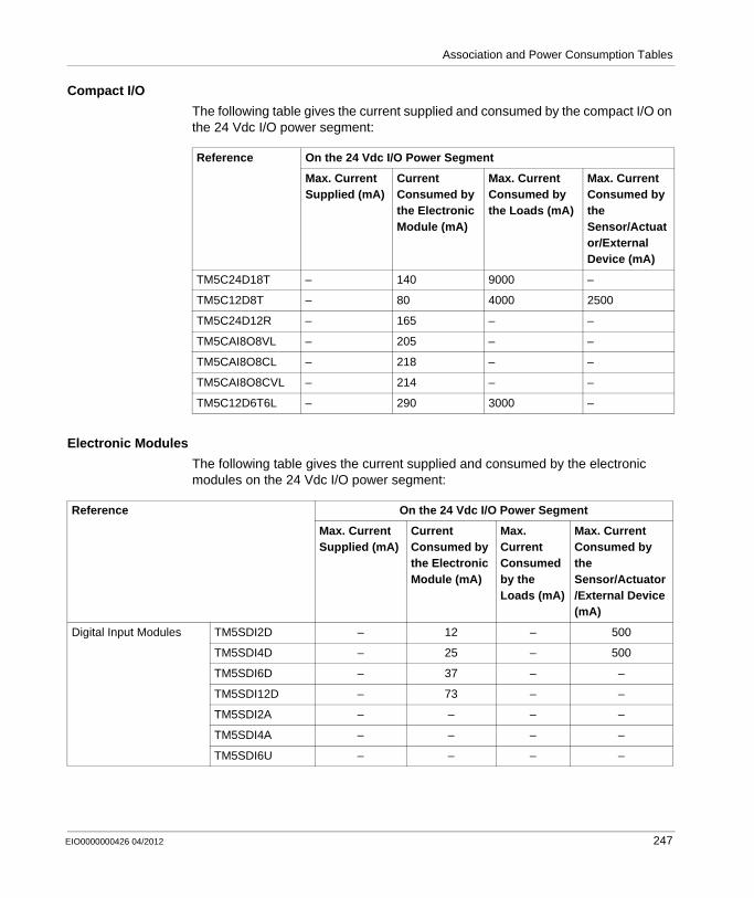
Association and Power Consumption Tables
Compact I/O
The following table gives the current supplied and consumed by the compact I/O on the 24 Vdc I/O power segment:
Electronic Modules
The following table gives the current supplied and consumed by the electronic modules on the 24 Vdc I/O power segment:
Reference On the 24 Vdc I/O Power Segment
Max. Current Supplied (mA)
Current Consumed by the Electronic Module (mA)
Max. Current Consumed by the Loads (mA)
Max. Current Consumed by the Sensor/Actuator/External Device (mA)
TM5C24D18T – 140 9000 –
TM5C12D8T – 80 4000 2500
TM5C24D12R – 165 – –
TM5CAI8O8VL – 205 – –
TM5CAI8O8CL – 218 – –
TM5CAI8O8CVL – 214 – –
TM5C12D6T6L – 290 3000 –
Reference On the 24 Vdc I/O Power Segment
Max. Current Supplied (mA)
Current Consumed by the Electronic Module (mA)
Max. Current Consumed by the Loads (mA)
Max. Current Consumed by the Sensor/Actuator/External Device (mA)
Digital Input Modules TM5SDI2D – 12 – 500
TM5SDI4D – 25 – 500
TM5SDI6D – 37 – –
TM5SDI12D – 73 – –
TM5SDI2A – – – –
TM5SDI4A – – – –
TM5SDI6U – – – –
EIO0000000426 04/2012 247
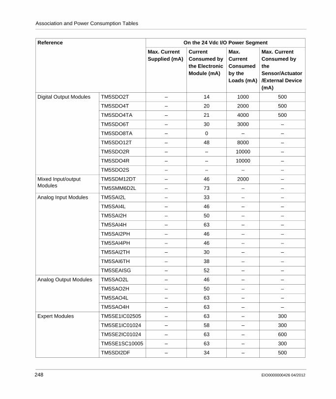
Association and Power Consumption Tables
Digital Output Modules TM5SDO2T – 14 1000 500
TM5SDO4T – 20 2000 500
TM5SDO4TA – 21 4000 500
TM5SDO6T – 30 3000 –
TM5SDO8TA – 0 – –
TM5SDO12T – 48 8000 –
TM5SDO2R – – 10000 –
TM5SDO4R – – 10000 –
TM5SDO2S – – – –
Mixed Input/output Modules
TM5SDM12DT – 46 2000 –
TM5SMM6D2L – 73 – –
Analog Input Modules TM5SAI2L – 33 – –
TM5SAI4L – 46 – –
TM5SAI2H – 50 – –
TM5SAI4H – 63 – –
TM5SAI2PH – 46 – –
TM5SAI4PH – 46 – –
TM5SAI2TH – 30 – –
TM5SAI6TH – 38 – –
TM5SEAISG – 52 – –
Analog Output Modules TM5SAO2L – 46 – –
TM5SAO2H – 50 – –
TM5SAO4L – 63 – –
TM5SAO4H – 63 – –
Expert Modules TM5SE1IC02505 – 63 – 300
TM5SE1IC01024 – 58 – 300
TM5SE2IC01024 – 63 – 600
TM5SE1SC10005 – 63 – 300
TM5SDI2DF – 34 – 500
Reference On the 24 Vdc I/O Power Segment
Max. Current Supplied (mA)
Current Consumed by the Electronic Module (mA)
Max. Current Consumed by the Loads (mA)
Max. Current Consumed by the Sensor/Actuator/External Device (mA)
248 EIO0000000426 04/2012
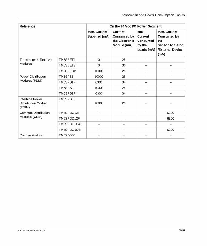
Association and Power Consumption Tables
Transmitter & Receiver Modules
TM5SBET1 0 25 – –
TM5SBET7 0 30 – –
TM5SBER2 10000 25 – –
Power Distribution Modules (PDM)
TM5SPS1 10000 25 – –
TM5SPS1F 6300 34 – –
TM5SPS2 10000 25 – –
TM5SPS2F 6300 34 – –
Interface Power Distribution Module (IPDM)
TM5SPS310000 25 – –
Common Distribution Modules (CDM)
TM5SPDG12F – – – 6300
TM5SPDD12F – – – 6300
TM5SPDG5D4F – – – –
TM5SPDG6D6F – – – 6300
Dummy Module TM5SD000 – – – –
Reference On the 24 Vdc I/O Power Segment
Max. Current Supplied (mA)
Current Consumed by the Electronic Module (mA)
Max. Current Consumed by the Loads (mA)
Max. Current Consumed by the Sensor/Actuator/External Device (mA)
EIO0000000426 04/2012 249
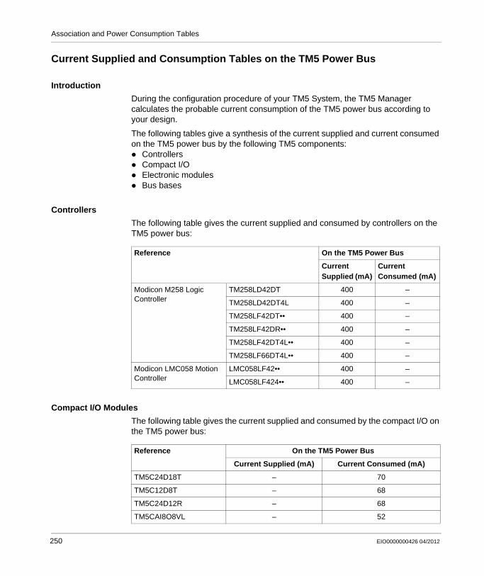
Association and Power Consumption Tables
Current Supplied and Consumption Tables on the TM5 Power Bus
Introduction
During the configuration procedure of your TM5 System, the TM5 Manager calculates the probable current consumption of the TM5 power bus according to your design.
The following tables give a synthesis of the current supplied and current consumed on the TM5 power bus by the following TM5 components:
ControllersCompact I/OElectronic modulesBus bases
Controllers
The following table gives the current supplied and consumed by controllers on the TM5 power bus:
Compact I/O Modules
The following table gives the current supplied and consumed by the compact I/O on the TM5 power bus:
Reference On the TM5 Power Bus
Current Supplied (mA)
Current Consumed (mA)
Modicon M258 Logic Controller
TM258LD42DT 400 –
TM258LD42DT4L 400 –
TM258LF42DT•• 400 –
TM258LF42DR•• 400 –
TM258LF42DT4L•• 400 –
TM258LF66DT4L•• 400 –
Modicon LMC058 Motion Controller
LMC058LF42•• 400 –
LMC058LF424•• 400 –
Reference On the TM5 Power Bus
Current Supplied (mA) Current Consumed (mA)
TM5C24D18T – 70
TM5C12D8T – 68
TM5C24D12R – 68
TM5CAI8O8VL – 52
250 EIO0000000426 04/2012
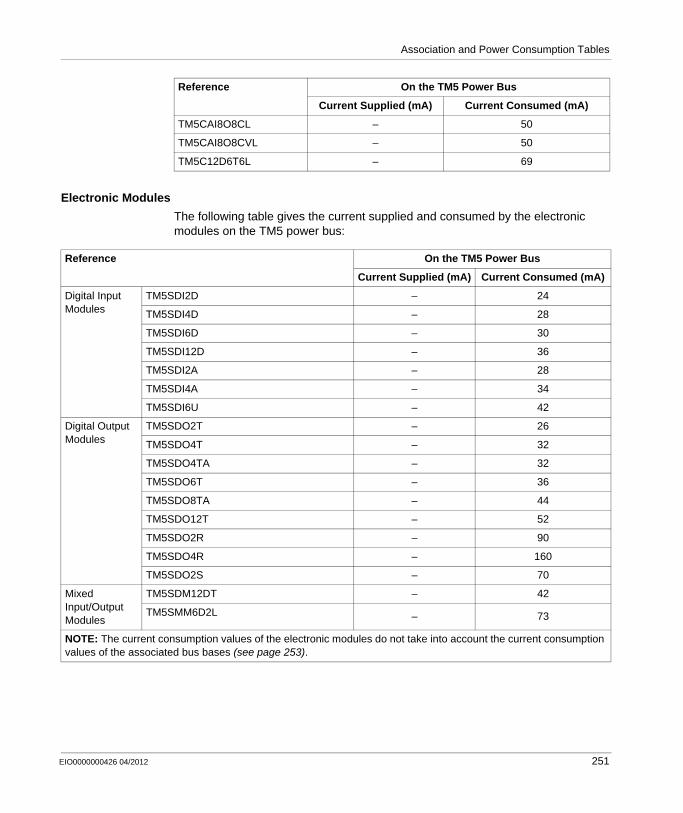
Association and Power Consumption Tables
Electronic Modules
The following table gives the current supplied and consumed by the electronic modules on the TM5 power bus:
TM5CAI8O8CL – 50
TM5CAI8O8CVL – 50
TM5C12D6T6L – 69
Reference On the TM5 Power Bus
Current Supplied (mA) Current Consumed (mA)
Reference On the TM5 Power Bus
Current Supplied (mA) Current Consumed (mA)
Digital Input Modules
TM5SDI2D – 24
TM5SDI4D – 28
TM5SDI6D – 30
TM5SDI12D – 36
TM5SDI2A – 28
TM5SDI4A – 34
TM5SDI6U – 42
Digital Output Modules
TM5SDO2T – 26
TM5SDO4T – 32
TM5SDO4TA – 32
TM5SDO6T – 36
TM5SDO8TA – 44
TM5SDO12T – 52
TM5SDO2R – 90
TM5SDO4R – 160
TM5SDO2S – 70
Mixed Input/Output Modules
TM5SDM12DT – 42
TM5SMM6D2L – 73
NOTE: The current consumption values of the electronic modules do not take into account the current consumption values of the associated bus bases (see page 253).
EIO0000000426 04/2012 251
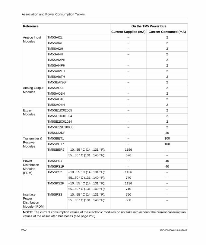
Association and Power Consumption Tables
Analog Input Modules
TM5SAI2L – 2
TM5SAI4L – 2
TM5SAI2H – 2
TM5SAI4H – 2
TM5SAI2PH – 2
TM5SAI4PH – 2
TM5SAI2TH – 2
TM5SAI6TH – 2
TM5SEAISG – 2
Analog Output Modules
TM5SAO2L – 2
TM5SAO2H – 2
TM5SAO4L – 2
TM5SAO4H – 2
Expert Modules
TM5SE1IC02505 – 2
TM5SE1IC01024 – 2
TM5SE2IC01024 – 2
TM5SE1SC10005 – 2
TM5SDI2DF – 30
Transmitter & Receiver Modules
TM5SBET1 – 100
TM5SBET7 – 100
TM5SBER2 –10...55 ° C (14...131 ° F): 1156 –
55...60 ° C (131...140 ° F): 676 –
Power Distribution Modules (PDM)
TM5SPS1 – 40
TM5SPS1F – 40
TM5SPS2 –10...55 ° C (14...131 ° F): 1136 –
55...60 ° C (131...140 ° F): 740 –
TM5SPS2F –10...55 ° C (14...131 ° F): 1136 –
55...60 ° C (131...140 ° F): 740 –
Interface Power Distribution Module (IPDM)
TM5SPS3 –10...55 ° C (14...131 ° F): 750 –
55...60 ° C (131...140 ° F): 500 –
Reference On the TM5 Power Bus
Current Supplied (mA) Current Consumed (mA)
NOTE: The current consumption values of the electronic modules do not take into account the current consumption values of the associated bus bases (see page 253).
252 EIO0000000426 04/2012
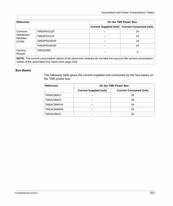
Association and Power Consumption Tables
Bus Bases
The following table gives the current supplied and consumed by the bus bases on the TM5 power bus:
Common Distribution Modules (CDM)
TM5SPDG12F – 24
TM5SPDD12F – 24
TM5SPDG5D4F – 24
TM5SPDG6D6F – 24
Dummy Module
TM5SD000– 0
Reference On the TM5 Power Bus
Current Supplied (mA) Current Consumed (mA)
NOTE: The current consumption values of the electronic modules do not take into account the current consumption values of the associated bus bases (see page 253).
Reference On the TM5 Power Bus
Current Supplied (mA) Current Consumed (mA)
TM5ACBM11 – 26
TM5ACBM15 – 26
TM5ACBM01R – 26
TM5ACBM05R – 26
TM5ACBM12 – 26
EIO0000000426 04/2012 253

Association and Power Consumption Tables
A.3 TM7 Power Consumption Tables
Introduction
This section gives the current supplied and consumption tables useful for designing your TM7 System.
What’s in this Section?
This section contains the following topics:
Topic Page
Current Supplied and Consumption Tables on the 24 Vdc I/O Power Segment 255
Current Supplied and Consumption Tables on the TM7 Power Bus 257
254 EIO0000000426 04/2012

Association and Power Consumption Tables
Current Supplied and Consumption Tables on the 24 Vdc I/O Power Segment
Introduction
During the configuration procedure of your TM7 System, the TM5 manager (see Modicon TM7, Expansion Blocks Configuration, Programming Guide) checks the current consumption on each 24 Vdc power segment according to your design.
The following tables give a synthesis of the current supplied and current consumed on the 24 Vdc I/O power segment by the TM7 blocks.
NOTE: There is no current supplied or consumed by the TM7 Power Distribution Block (PDB) on the 24 Vdc I/O power segment.
TM7 Field Bus Interface I/O Block
The following table gives the current supplied and consumed by the TM7 field bus interface I/O blocks on the 24 Vdc I/O power segment:
TM7 Blocks
The following table gives the current supplied and consumed by the TM7 blocks on the 24 Vdc I/O power segment:
Reference On the 24 Vdc I/O Power Segment
Max. Current Supplied (mA)
Current Consumed by the Electronic (mA)
Max. Current Consumed by the Loads (mA)
Max. Current Consumed by the Sensor/Actuator (mA)
TM7 Field Bus Interface I/O Block
TM7NCOM08B 4000 84 4000 500
TM7NCOM16B 4000 125 4000 500
TM7NCOM16A 4000 125 4000 500
Reference On the 24 Vdc I/O Power Segment
Max. Current
Supplied(1) (mA)
Current Consumed by the Electronic (mA)
Max. Current Consumed by the Loads (mA)
Max. Current Consumed by the Sensor/Actuator (mA)
Digital input TM7BDI8B 8000 42 – 500
TM7BDI16B 8000 21 – 500
TM7BDI16A 8000 21 – 500
Digital output TM7BDO8TAB 8000 84 8000 500
(1) When connecting the 24 Vdc I/O power IN connector to an external power supply
EIO0000000426 04/2012 255

Association and Power Consumption Tables
Digital mixed input/output TM7BDM8B 8000 105 4000 500
TM7BDM16A 8000 125 8000 500
TM7BDM16B 8000 125 8000 500
Analog input TM7BAI4VLA 8000 125 – 500
TM7BAI4CLA 8000 125 – 500
TM7BAI4TLA 8000 63 – –
TM7BAI4PLA 8000 108 – –
Analog output TM7BAO4VLA 8000 167 – 500
TM7BAO4CLA 8000 188 – 500
Analog mixed input/output TM7BAM4VLA 8000 125 – 500
TM7BAM4CLA 8000 125 – 500
Reference On the 24 Vdc I/O Power Segment
Max. Current
Supplied(1) (mA)
Current Consumed by the Electronic (mA)
Max. Current Consumed by the Loads (mA)
Max. Current Consumed by the Sensor/Actuator (mA)
(1) When connecting the 24 Vdc I/O power IN connector to an external power supply
256 EIO0000000426 04/2012

Association and Power Consumption Tables
Current Supplied and Consumption Tables on the TM7 Power Bus
Introduction
During the configuration procedure of your TM7 System, the TM5 Manager (see Modicon TM7, Expansion Blocks Configuration, Programming Guide) calculates the probable current consumption of the TM7 power bus according to your design.
The following tables give a synthesis of the current supplied and current consumed on the TM7 power bus by the following TM5 / TM7 components:
TM5SBET7 Transmitter module,TM7 expansion blocks (Field bus interface I/O blocks, I/O blocks and Power Distribution Block).
TM5SBET7 Transmitter Module
For information on the current supplied to the TM7 power bus, refer to Supplying the TM7 Power Bus (see page 197).
Expansion Blocks
The following table gives the current supplied and consumed by the expansion blocks on the TM7 power bus:
Reference On the TM7 Power Bus
Current Supplied (mA) Current Consumed (mA)
TM7 Field bus interface I/O blocks
TM7NCOM08B 150 –
TM7NCOM16B 750 –
TM7NCOM16A 750 –
Digital input TM7BDI8B – 38
TM7BDI16B – 38
TM7BDI16A – 38
Digital output TM7BDO8TAB – 38
Digital mixed input/output
TM7BDM8B – 38
TM7BDM16A – 38
TM7BDM16B – 38
Analog input TM7BAI4VLA – 38
TM7BAI4CLA – 38
TM7BAI4TLA – 38
TM7BAI4PLA – 38
EIO0000000426 04/2012 257
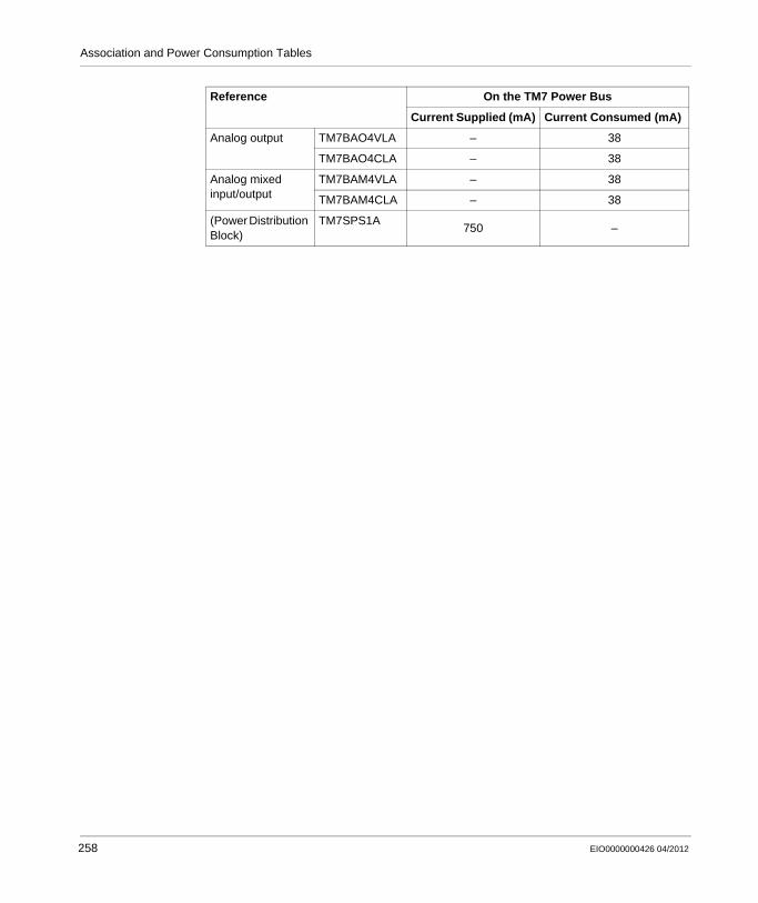
Association and Power Consumption Tables
Analog output TM7BAO4VLA – 38
TM7BAO4CLA – 38
Analog mixed input/output
TM7BAM4VLA – 38
TM7BAM4CLA – 38
(Power Distribution Block)
TM7SPS1A750 –
Reference On the TM7 Power Bus
Current Supplied (mA) Current Consumed (mA)
258 EIO0000000426 04/2012
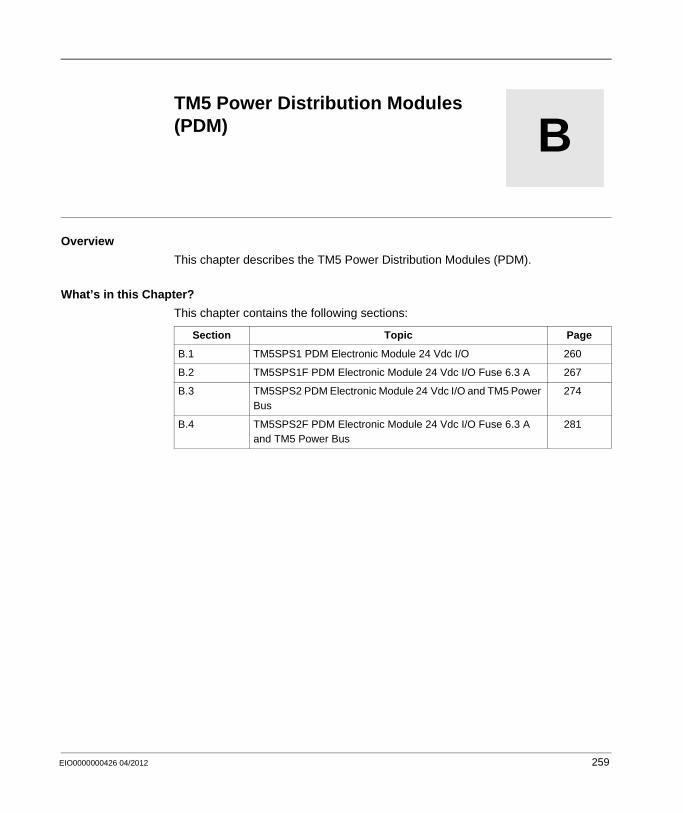
EIO0000000426 04/2012
B
Modicon TM5 / TM7 Flexible System
TM5 Power Distribution Modules
EIO0000000426 04/2012
TM5 Power Distribution Modules (PDM)
Overview
This chapter describes the TM5 Power Distribution Modules (PDM).
What’s in this Chapter?
This chapter contains the following sections:
Section Topic Page
B.1 TM5SPS1 PDM Electronic Module 24 Vdc I/O 260
B.2 TM5SPS1F PDM Electronic Module 24 Vdc I/O Fuse 6.3 A 267
B.3 TM5SPS2 PDM Electronic Module 24 Vdc I/O and TM5 Power Bus
274
B.4 TM5SPS2F PDM Electronic Module 24 Vdc I/O Fuse 6.3 A and TM5 Power Bus
281
259
TM5 Power Distribution Modules
B.1 TM5SPS1 PDM Electronic Module 24 Vdc I/O
What’s in this Section?
This section contains the following topics:
Topic Page
TM5SPS1 Presentation 261
TM5SPS1 Characteristics 263
TM5SPS1 Wiring Diagram 265
260 EIO0000000426 04/2012
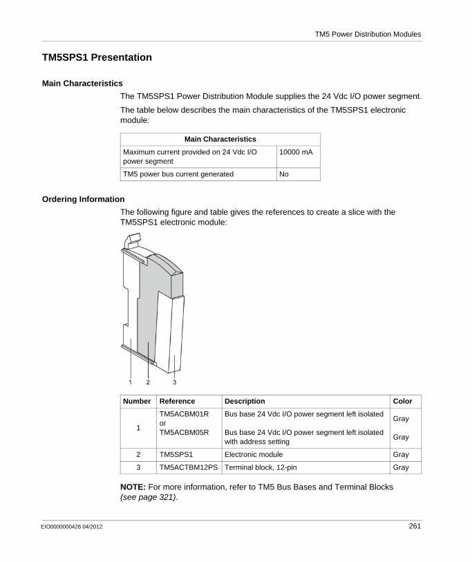
TM5 Power Distribution Modules
TM5SPS1 Presentation
Main Characteristics
The TM5SPS1 Power Distribution Module supplies the 24 Vdc I/O power segment.
The table below describes the main characteristics of the TM5SPS1 electronic module:
Ordering Information
The following figure and table gives the references to create a slice with the TM5SPS1 electronic module:
NOTE: For more information, refer to TM5 Bus Bases and Terminal Blocks (see page 321).
Main Characteristics
Maximum current provided on 24 Vdc I/O power segment
10000 mA
TM5 power bus current generated No
Number Reference Description Color
1
TM5ACBM01RorTM5ACBM05R
Bus base 24 Vdc I/O power segment left isolated
Bus base 24 Vdc I/O power segment left isolated with address setting
Gray
Gray
2 TM5SPS1 Electronic module Gray
3 TM5ACTBM12PS Terminal block, 12-pin Gray
EIO0000000426 04/2012 261
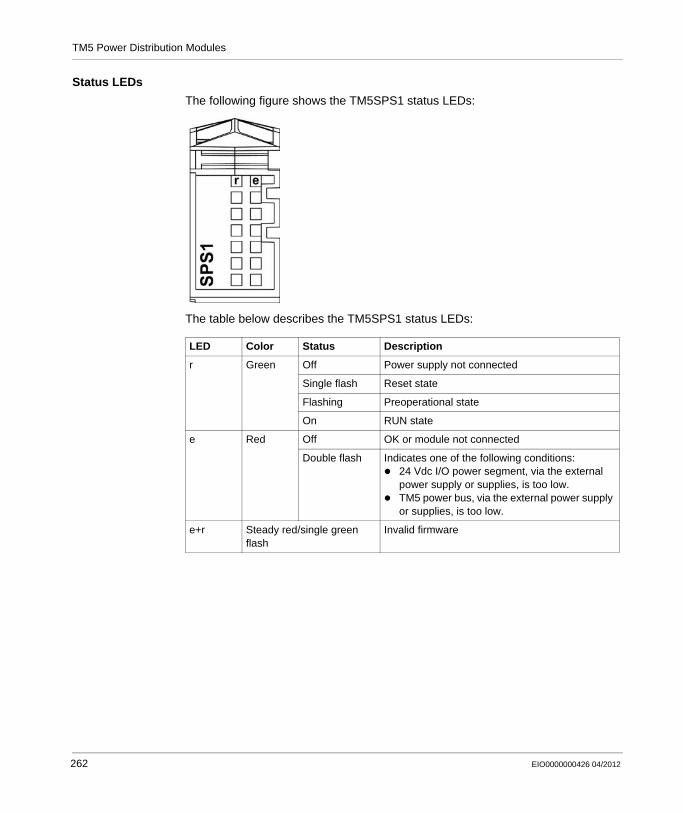
TM5 Power Distribution Modules
Status LEDs
The following figure shows the TM5SPS1 status LEDs:
The table below describes the TM5SPS1 status LEDs:
LED Color Status Description
r Green Off Power supply not connected
Single flash Reset state
Flashing Preoperational state
On RUN state
e Red Off OK or module not connected
Double flash Indicates one of the following conditions:24 Vdc I/O power segment, via the external power supply or supplies, is too low.TM5 power bus, via the external power supply or supplies, is too low.
e+r Steady red/single green flash
Invalid firmware
262 EIO0000000426 04/2012

TM5 Power Distribution Modules
TM5SPS1 Characteristics
Introduction
This section gives the TM5SPS1 electronic module characteristics.
See also Environmental Characteristics (see page 68).
General Characteristics
The following table shows the general characteristics of the TM5SPS1 electronic module:
DANGERFIRE HAZARD
Use only the recommended wire sizes for I/O channels and power supplies.
Failure to follow these instructions will result in death or serious injury.
WARNINGUNINTENDED EQUIPMENT OPERATION
Do not exceed any of the rated values specified in the following tables.
Failure to follow these instructions can result in death, serious injury, or equipment damage.
General Characteristics
Rated power supply voltage 24 Vdc
24 Vdc I/O power segment current draw 25 mA
TM5 power bus 5 Vdc current draw 40 mA
Power dissipation 0.8 W max.
Weight 30 g (1.1 oz)
ID code 7167 dec
EIO0000000426 04/2012 263
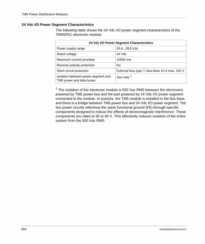
TM5 Power Distribution Modules
24 Vdc I/O Power Segment Characteristics
The following table shows the 24 Vdc I/O power segment characteristics of the TM5SPS1 electronic module:
1 The isolation of the electronic module is 500 Vac RMS between the electronics powered by TM5 power bus and the part powered by 24 Vdc I/O power segment connected to the module. In practice, the TM5 module is installed in the bus base, and there is a bridge between TM5 power bus and 24 Vdc I/O power segment. The two power circuits reference the same functional ground (FE) through specific components designed to reduce the effects of electromagnetic interference. These components are rated at 30 or 60 V. This effectively reduces isolation of the entire system from the 500 Vac RMS.
24 Vdc I/O Power Segment Characteristics
Power supply range 20.4...28.8 Vdc
Rated voltage 24 Vdc
Maximum current provided 10000 mA
Reverse polarity protection No
Short circuit protection External fuse type T slow-blow 10 A max. 250 V
Isolation between power segment and TM5 power and data buses
See note 1
264 EIO0000000426 04/2012
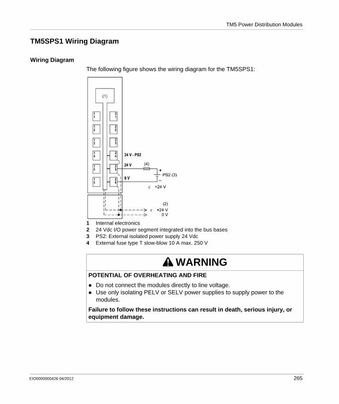
TM5 Power Distribution Modules
TM5SPS1 Wiring Diagram
Wiring Diagram
The following figure shows the wiring diagram for the TM5SPS1:
1 Internal electronics2 24 Vdc I/O power segment integrated into the bus bases3 PS2: External isolated power supply 24 Vdc4 External fuse type T slow-blow 10 A max. 250 V
WARNINGPOTENTIAL OF OVERHEATING AND FIRE
Do not connect the modules directly to line voltage.Use only isolating PELV or SELV power supplies to supply power to the modules.
Failure to follow these instructions can result in death, serious injury, or equipment damage.
EIO0000000426 04/2012 265

TM5 Power Distribution Modules
WARNINGUNINTENDED EQUIPMENT OPERATION
Do not connect wires to unused terminals or terminals marked “Not Connected (N.C.)”.
Failure to follow these instructions can result in death, serious injury, or equipment damage.
266 EIO0000000426 04/2012

TM5 Power Distribution Modules
B.2 TM5SPS1F PDM Electronic Module 24 Vdc I/O Fuse 6.3 A
What’s in this Section?
This section contains the following topics:
Topic Page
TM5SPS1F Presentation 268
TM5SPS1F Characteristics 270
TM5SPS1F Wiring Diagram 272
EIO0000000426 04/2012 267

TM5 Power Distribution Modules
TM5SPS1F Presentation
Main Characteristics
The TM5SPS1F power distribution module feeds the 24 Vdc I/O power segment through an exchangeable fuse.
The table below describes the main characteristics of the TM5SPS1F electronic module:
Ordering Information
The following figure and table gives the references to create a slice with the TM5SPS1F electronic module:
NOTE: For more information, refer to TM5 Bus Bases and Terminal Blocks (see page 321).
Main Characteristics
Maximum current provided on 24 Vdc I/O power segment
6300 mA
TM5 power bus current generated No
Number Model Number Description Color
1
TM5ACBM01RorTM5ACBM05R
Bus base 24 Vdc I/O power segment left isolated
Bus base 24 Vdc I/O power segment left isolated with address setting
Gray
Gray
2 TM5SPS1F Electronic module Gray
3 TM5ACTBM12PS Terminal block, 12-pin Gray
268 EIO0000000426 04/2012
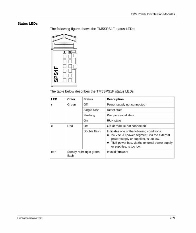
TM5 Power Distribution Modules
Status LEDs
The following figure shows the TM5SPS1F status LEDs:
The table below describes the TM5SPS1F status LEDs:
LED Color Status Description
r Green Off Power supply not connected
Single flash Reset state
Flashing Preoperational state
On RUN state
e Red Off OK or module not connected
Double flash Indicates one of the following conditions:24 Vdc I/O power segment, via the external power supply or supplies, is too low.TM5 power bus, via the external power supply or supplies, is too low.
e+r Steady red/single green flash
Invalid firmware
EIO0000000426 04/2012 269
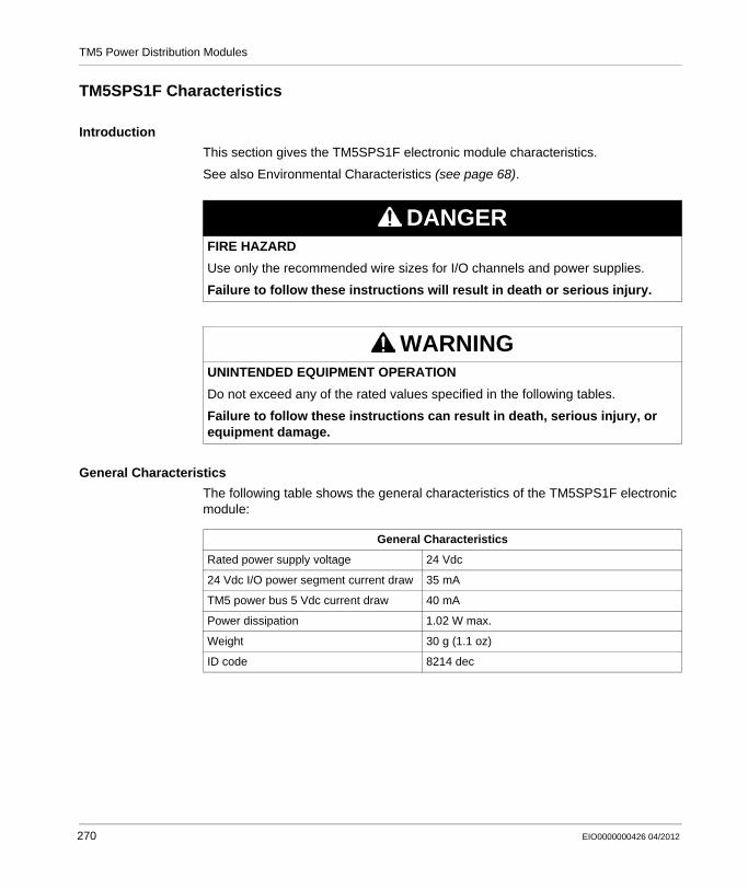
TM5 Power Distribution Modules
TM5SPS1F Characteristics
Introduction
This section gives the TM5SPS1F electronic module characteristics.
See also Environmental Characteristics (see page 68).
General Characteristics
The following table shows the general characteristics of the TM5SPS1F electronic module:
DANGERFIRE HAZARD
Use only the recommended wire sizes for I/O channels and power supplies.
Failure to follow these instructions will result in death or serious injury.
WARNINGUNINTENDED EQUIPMENT OPERATION
Do not exceed any of the rated values specified in the following tables.
Failure to follow these instructions can result in death, serious injury, or equipment damage.
General Characteristics
Rated power supply voltage 24 Vdc
24 Vdc I/O power segment current draw 35 mA
TM5 power bus 5 Vdc current draw 40 mA
Power dissipation 1.02 W max.
Weight 30 g (1.1 oz)
ID code 8214 dec
270 EIO0000000426 04/2012
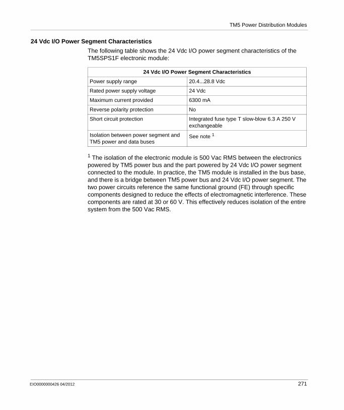
TM5 Power Distribution Modules
24 Vdc I/O Power Segment Characteristics
The following table shows the 24 Vdc I/O power segment characteristics of the TM5SPS1F electronic module:
1 The isolation of the electronic module is 500 Vac RMS between the electronics powered by TM5 power bus and the part powered by 24 Vdc I/O power segment connected to the module. In practice, the TM5 module is installed in the bus base, and there is a bridge between TM5 power bus and 24 Vdc I/O power segment. The two power circuits reference the same functional ground (FE) through specific components designed to reduce the effects of electromagnetic interference. These components are rated at 30 or 60 V. This effectively reduces isolation of the entire system from the 500 Vac RMS.
24 Vdc I/O Power Segment Characteristics
Power supply range 20.4...28.8 Vdc
Rated power supply voltage 24 Vdc
Maximum current provided 6300 mA
Reverse polarity protection No
Short circuit protection Integrated fuse type T slow-blow 6.3 A 250 V exchangeable
Isolation between power segment and TM5 power and data buses
See note 1
EIO0000000426 04/2012 271
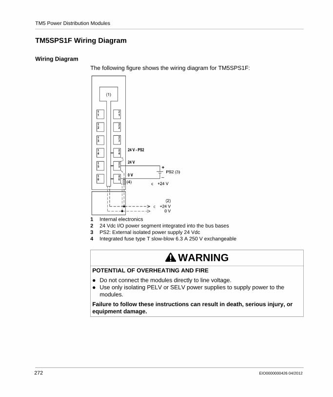
TM5 Power Distribution Modules
TM5SPS1F Wiring Diagram
Wiring Diagram
The following figure shows the wiring diagram for TM5SPS1F:
1 Internal electronics2 24 Vdc I/O power segment integrated into the bus bases3 PS2: External isolated power supply 24 Vdc4 Integrated fuse type T slow-blow 6.3 A 250 V exchangeable
WARNINGPOTENTIAL OF OVERHEATING AND FIRE
Do not connect the modules directly to line voltage.Use only isolating PELV or SELV power supplies to supply power to the modules.
Failure to follow these instructions can result in death, serious injury, or equipment damage.
272 EIO0000000426 04/2012

TM5 Power Distribution Modules
WARNINGUNINTENDED EQUIPMENT OPERATION
Do not connect wires to unused terminals or terminals marked “Not Connected (N.C.)”.
Failure to follow these instructions can result in death, serious injury, or equipment damage.
EIO0000000426 04/2012 273
TM5 Power Distribution Modules
B.3 TM5SPS2 PDM Electronic Module 24 Vdc I/O and TM5 Power Bus
What’s in this Section?
This section contains the following topics:
Topic Page
TM5SPS2 Presentation 275
TM5SPS2 Characteristics 277
TM5SPS2 Wiring Diagram 279
274 EIO0000000426 04/2012
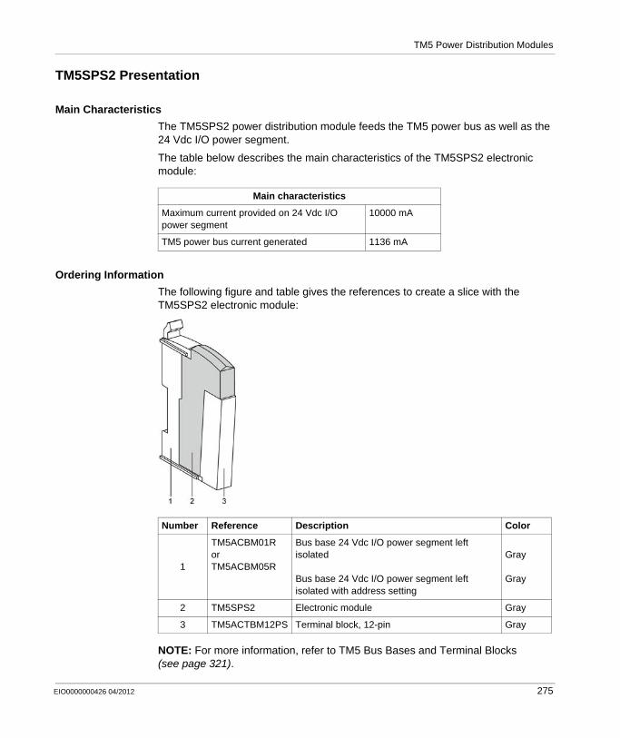
TM5 Power Distribution Modules
TM5SPS2 Presentation
Main Characteristics
The TM5SPS2 power distribution module feeds the TM5 power bus as well as the 24 Vdc I/O power segment.
The table below describes the main characteristics of the TM5SPS2 electronic module:
Ordering Information
The following figure and table gives the references to create a slice with the TM5SPS2 electronic module:
NOTE: For more information, refer to TM5 Bus Bases and Terminal Blocks (see page 321).
Main characteristics
Maximum current provided on 24 Vdc I/O power segment
10000 mA
TM5 power bus current generated 1136 mA
Number Reference Description Color
1
TM5ACBM01RorTM5ACBM05R
Bus base 24 Vdc I/O power segment left isolated
Bus base 24 Vdc I/O power segment left isolated with address setting
Gray
Gray
2 TM5SPS2 Electronic module Gray
3 TM5ACTBM12PS Terminal block, 12-pin Gray
EIO0000000426 04/2012 275
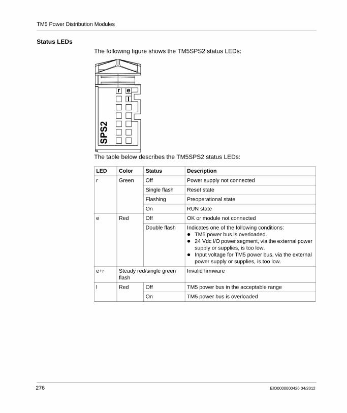
TM5 Power Distribution Modules
Status LEDs
The following figure shows the TM5SPS2 status LEDs:
The table below describes the TM5SPS2 status LEDs:
LED Color Status Description
r Green Off Power supply not connected
Single flash Reset state
Flashing Preoperational state
On RUN state
e Red Off OK or module not connected
Double flash Indicates one of the following conditions:TM5 power bus is overloaded.24 Vdc I/O power segment, via the external power supply or supplies, is too low.Input voltage for TM5 power bus, via the external power supply or supplies, is too low.
e+r Steady red/single green flash
Invalid firmware
l Red Off TM5 power bus in the acceptable range
On TM5 power bus is overloaded
276 EIO0000000426 04/2012
TM5 Power Distribution Modules
TM5SPS2 Characteristics
Introduction
This section gives the TM5SPS2 electronic module characteristics.
See also Environmental Characteristics (see page 68).
General Characteristics
The following table shows the general characteristics of the TM5SPS2 electronic module:
TM5 Power Bus Characteristics
The following table shows the TM5 power bus characteristics of the TM5SPS2 electronic module:
DANGERFIRE HAZARD
Use only the recommended wire sizes for I/O channels and power supplies.
Failure to follow these instructions will result in death or serious injury.
WARNINGUNINTENDED EQUIPMENT OPERATION
Do not exceed any of the rated values specified in the following tables.
Failure to follow these instructions can result in death, serious injury, or equipment damage.
General Characteristics
Rated power supply voltage 24 Vdc
24 Vdc I/O power segment current draw 25 mA
Power dissipation 1.91 W max.
Weight 30 g (1.1 oz)
ID code 7104 dec
TM5 Power Bus Characteristics
Power supply range 20.4...28.8 Vdc
Rated input current 0.7 A max. at 24 Vdc
EIO0000000426 04/2012 277
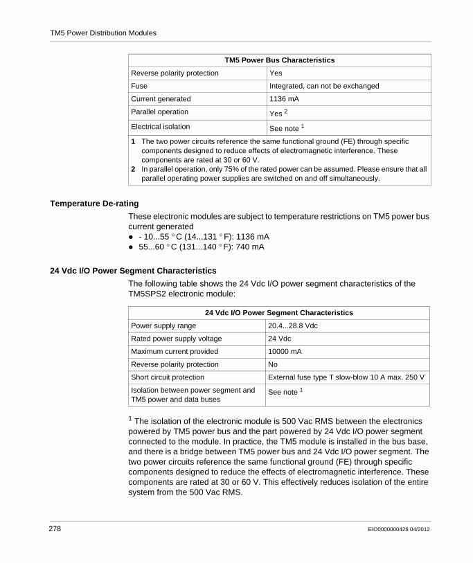
TM5 Power Distribution Modules
Temperature De-rating
These electronic modules are subject to temperature restrictions on TM5 power bus current generated
- 10...55 ° C (14...131 ° F): 1136 mA55...60 ° C (131...140 ° F): 740 mA
24 Vdc I/O Power Segment Characteristics
The following table shows the 24 Vdc I/O power segment characteristics of the TM5SPS2 electronic module:
1 The isolation of the electronic module is 500 Vac RMS between the electronics powered by TM5 power bus and the part powered by 24 Vdc I/O power segment connected to the module. In practice, the TM5 module is installed in the bus base, and there is a bridge between TM5 power bus and 24 Vdc I/O power segment. The two power circuits reference the same functional ground (FE) through specific components designed to reduce the effects of electromagnetic interference. These components are rated at 30 or 60 V. This effectively reduces isolation of the entire system from the 500 Vac RMS.
Reverse polarity protection Yes
Fuse Integrated, can not be exchanged
Current generated 1136 mA
Parallel operation Yes 2
Electrical isolation See note 1
1 The two power circuits reference the same functional ground (FE) through specific components designed to reduce effects of electromagnetic interference. These components are rated at 30 or 60 V.
2 In parallel operation, only 75% of the rated power can be assumed. Please ensure that all parallel operating power supplies are switched on and off simultaneously.
TM5 Power Bus Characteristics
24 Vdc I/O Power Segment Characteristics
Power supply range 20.4...28.8 Vdc
Rated power supply voltage 24 Vdc
Maximum current provided 10000 mA
Reverse polarity protection No
Short circuit protection External fuse type T slow-blow 10 A max. 250 V
Isolation between power segment and TM5 power and data buses
See note 1
278 EIO0000000426 04/2012

TM5 Power Distribution Modules
TM5SPS2 Wiring Diagram
Wiring Diagram
The following figure shows the wiring diagram for the TM5SPS2:
1 Internal electronics2 24 Vdc I/O power segment integrated into the bus bases3 PS1/PS2: External isolated power supplies 24 Vdc4 External fuse type T slow-blow 10 A max. 250 V5 External fuse type T slow-blow 1 A 250 V
WARNINGPOTENTIAL OF OVERHEATING AND FIRE
Do not connect the modules directly to line voltage.Use only isolating PELV or SELV power supplies to supply power to the modules.
Failure to follow these instructions can result in death, serious injury, or equipment damage.
EIO0000000426 04/2012 279

TM5 Power Distribution Modules
WARNINGUNINTENDED EQUIPMENT OPERATION
Do not connect wires to unused terminals or terminals marked “Not Connected (N.C.)”.
Failure to follow these instructions can result in death, serious injury, or equipment damage.
280 EIO0000000426 04/2012
TM5 Power Distribution Modules
B.4 TM5SPS2F PDM Electronic Module 24 Vdc I/O Fuse 6.3 A and TM5 Power Bus
What’s in this Section?
This section contains the following topics:
Topic Page
TM5SPS2F Presentation 282
TM5SPS2F Characteristics 284
TM5SPS2F Wiring Diagram 287
EIO0000000426 04/2012 281
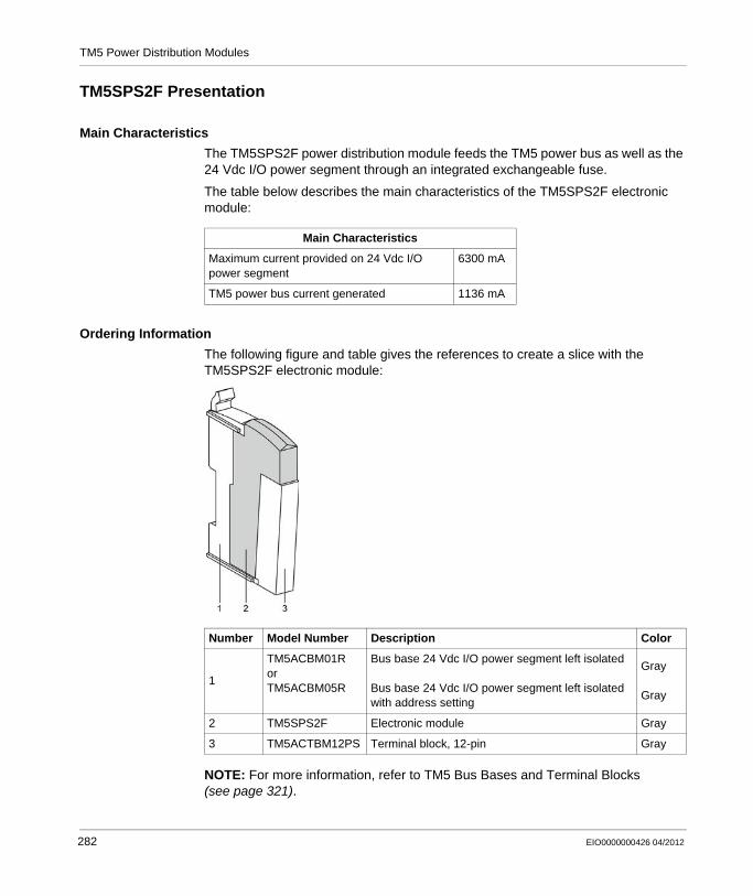
TM5 Power Distribution Modules
TM5SPS2F Presentation
Main Characteristics
The TM5SPS2F power distribution module feeds the TM5 power bus as well as the 24 Vdc I/O power segment through an integrated exchangeable fuse.
The table below describes the main characteristics of the TM5SPS2F electronic module:
Ordering Information
The following figure and table gives the references to create a slice with the TM5SPS2F electronic module:
NOTE: For more information, refer to TM5 Bus Bases and Terminal Blocks (see page 321).
Main Characteristics
Maximum current provided on 24 Vdc I/O power segment
6300 mA
TM5 power bus current generated 1136 mA
Number Model Number Description Color
1
TM5ACBM01RorTM5ACBM05R
Bus base 24 Vdc I/O power segment left isolated
Bus base 24 Vdc I/O power segment left isolated with address setting
Gray
Gray
2 TM5SPS2F Electronic module Gray
3 TM5ACTBM12PS Terminal block, 12-pin Gray
282 EIO0000000426 04/2012
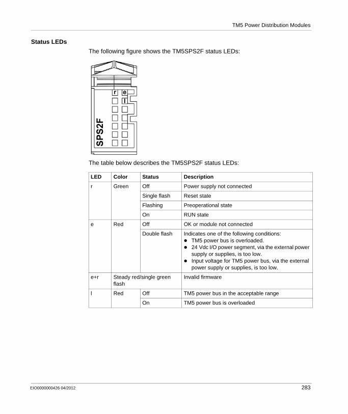
TM5 Power Distribution Modules
Status LEDs
The following figure shows the TM5SPS2F status LEDs:
The table below describes the TM5SPS2F status LEDs:
LED Color Status Description
r Green Off Power supply not connected
Single flash Reset state
Flashing Preoperational state
On RUN state
e Red Off OK or module not connected
Double flash Indicates one of the following conditions:TM5 power bus is overloaded.24 Vdc I/O power segment, via the external power supply or supplies, is too low.Input voltage for TM5 power bus, via the external power supply or supplies, is too low.
e+r Steady red/single green flash
Invalid firmware
l Red Off TM5 power bus in the acceptable range
On TM5 power bus is overloaded
EIO0000000426 04/2012 283

TM5 Power Distribution Modules
TM5SPS2F Characteristics
Introduction
This section gives the TM5SPS2F electronic module characteristics.
See also Environmental Characteristics (see page 68).
General Characteristics
The following table shows the general characteristics of the TM5SPS2F electronic module:
DANGERFIRE HAZARD
Use only the recommended wire sizes for I/O channels and power supplies.
Failure to follow these instructions will result in death or serious injury.
WARNINGUNINTENDED EQUIPMENT OPERATION
Do not exceed any of the rated values specified in the following tables.
Failure to follow these instructions can result in death, serious injury, or equipment damage.
General Characteristics
Rated power supply voltage 24 Vdc
24 Vdc I/O power segment current draw 35 mA
Power dissipation 2.13 W max.
Weight 30 g (1.1 oz)
ID code 8215 dec
284 EIO0000000426 04/2012
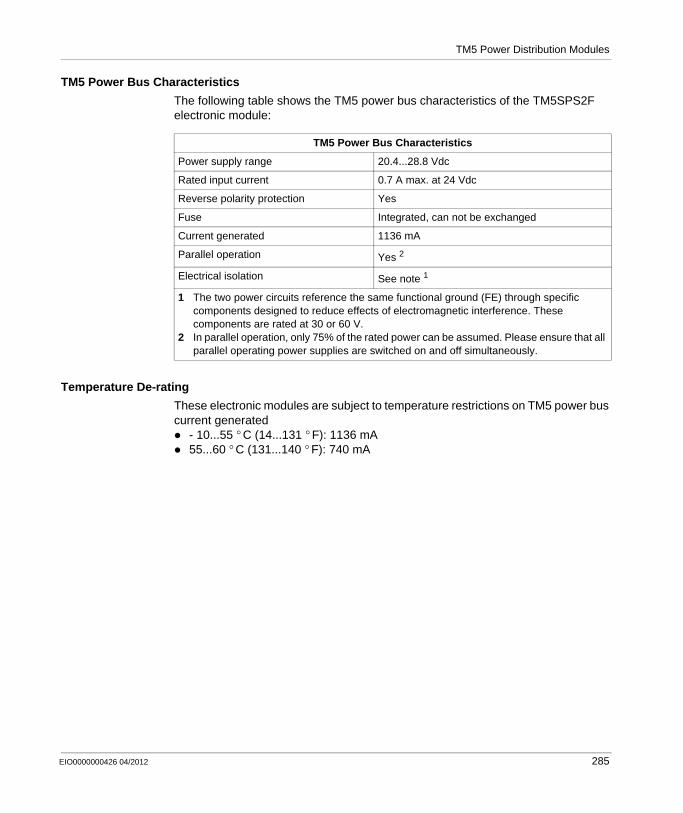
TM5 Power Distribution Modules
TM5 Power Bus Characteristics
The following table shows the TM5 power bus characteristics of the TM5SPS2F electronic module:
Temperature De-rating
These electronic modules are subject to temperature restrictions on TM5 power bus current generated
- 10...55 ° C (14...131 ° F): 1136 mA55...60 ° C (131...140 ° F): 740 mA
TM5 Power Bus Characteristics
Power supply range 20.4...28.8 Vdc
Rated input current 0.7 A max. at 24 Vdc
Reverse polarity protection Yes
Fuse Integrated, can not be exchanged
Current generated 1136 mA
Parallel operation Yes 2
Electrical isolation See note 1
1 The two power circuits reference the same functional ground (FE) through specific components designed to reduce effects of electromagnetic interference. These components are rated at 30 or 60 V.
2 In parallel operation, only 75% of the rated power can be assumed. Please ensure that all parallel operating power supplies are switched on and off simultaneously.
EIO0000000426 04/2012 285

TM5 Power Distribution Modules
24 Vdc I/O Power Segment Characteristics
The following table shows the 24 Vdc I/O power segment characteristics of the TM5SPS1 electronic module:
1 The isolation of the electronic module is 500 Vac RMS between the electronics powered by TM5 power bus and the part powered by 24 Vdc I/O power segment connected to the module. In practice, the TM5 module is installed in the bus base, and there is a bridge between TM5 power bus and 24 Vdc I/O power segment. The two power circuits reference the same functional ground (FE) through specific components designed to reduce the effects of electromagnetic interference. These components are rated at 30 or 60 V. This effectively reduces isolation of the entire system from the 500 Vac RMS.
24 Vdc I/O Power Segment Characteristics
Power supply range 20.4...28.8 Vdc
Rated power supply voltage 24 Vdc
Maximum current provided 6300 mA
Reverse polarity protection No
Short circuit protection Integrated fuse type T slow-blow 6.3 A 250 V exchangeable
Isolation between power segment and TM5 power and data buses
See note 1
286 EIO0000000426 04/2012
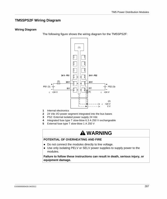
TM5 Power Distribution Modules
TM5SPS2F Wiring Diagram
Wiring Diagram
The following figure shows the wiring diagram for the TM5SPS2F:
1 Internal electronics2 24 Vdc I/O power segment integrated into the bus bases3 PS2: External isolated power supply 24 Vdc4 Integrated fuse type T slow-blow 6.3 A 250 V exchangeable5 External fuse type T slow-blow 1 A 250 V
WARNINGPOTENTIAL OF OVERHEATING AND FIRE
Do not connect the modules directly to line voltage.Use only isolating PELV or SELV power supplies to supply power to the modules.
Failure to follow these instructions can result in death, serious injury, or equipment damage.
EIO0000000426 04/2012 287

TM5 Power Distribution Modules
WARNINGUNINTENDED EQUIPMENT OPERATION
Do not connect wires to unused terminals or terminals marked “Not Connected (N.C.)”.
Failure to follow these instructions can result in death, serious injury, or equipment damage.
288 EIO0000000426 04/2012

EIO0000000426 04/2012
C
Modicon TM5 / TM7 Flexible System
TM5 Common Distribution Modules
EIO0000000426 04/2012
TM5 Common Distribution Modules (CDM)
Overview
This chapter describes TM5 Common Distribution Modules (CDM) for designing your TM5 System.
What’s in this Chapter?
This chapter contains the following sections:
Section Topic Page
C.1 TM5SPDG12F Electronic Module 12 x 0 Vdc 290
C.2 TM5SPDD12F Electronic Module 12 x 24 Vdc 298
C.3 TM5SPDG5D4F Electronic Module 5 x 0 Vdc and 5 x 24 Vdc 305
C.4 TM5SPDG6D6F Electronic Module 6 x 0 Vdc and 6 x 24 Vdc 312
289

TM5 Common Distribution Modules
C.1 TM5SPDG12F Electronic Module 12 x 0 Vdc
What’s in this Section?
This section contains the following topics:
Topic Page
TM5SPDG12F Presentation 291
TM5SPDG12F Characteristics 293
TM5SPDG12F Wiring Diagram 295
290 EIO0000000426 04/2012
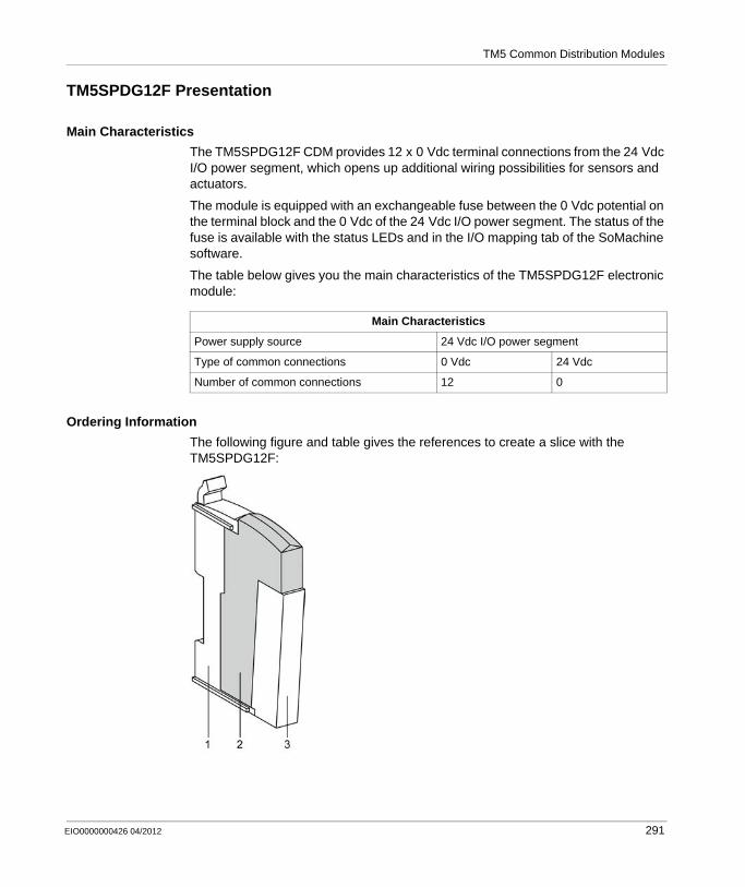
TM5 Common Distribution Modules
TM5SPDG12F Presentation
Main Characteristics
The TM5SPDG12F CDM provides 12 x 0 Vdc terminal connections from the 24 Vdc I/O power segment, which opens up additional wiring possibilities for sensors and actuators.
The module is equipped with an exchangeable fuse between the 0 Vdc potential on the terminal block and the 0 Vdc of the 24 Vdc I/O power segment. The status of the fuse is available with the status LEDs and in the I/O mapping tab of the SoMachine software.
The table below gives you the main characteristics of the TM5SPDG12F electronic module:
Ordering Information
The following figure and table gives the references to create a slice with the TM5SPDG12F:
Main Characteristics
Power supply source 24 Vdc I/O power segment
Type of common connections 0 Vdc 24 Vdc
Number of common connections 12 0
EIO0000000426 04/2012 291
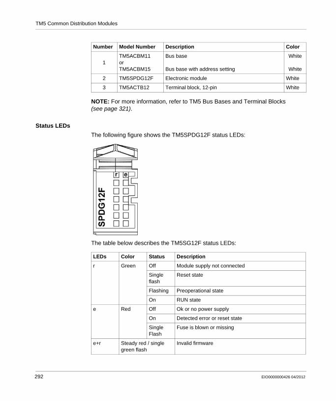
TM5 Common Distribution Modules
NOTE: For more information, refer to TM5 Bus Bases and Terminal Blocks (see page 321).
Status LEDs
The following figure shows the TM5SPDG12F status LEDs:
The table below describes the TM5SG12F status LEDs:
Number Model Number Description Color
1TM5ACBM11orTM5ACBM15
Bus base
Bus base with address setting
White
White
2 TM5SPDG12F Electronic module White
3 TM5ACTB12 Terminal block, 12-pin White
LEDs Color Status Description
r Green Off Module supply not connected
Single flash
Reset state
Flashing Preoperational state
On RUN state
e Red Off Ok or no power supply
On Detected error or reset state
Single Flash
Fuse is blown or missing
e+r Steady red / single green flash
Invalid firmware
292 EIO0000000426 04/2012
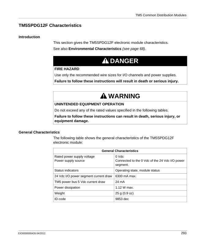
TM5 Common Distribution Modules
TM5SPDG12F Characteristics
Introduction
This section gives the TM5SPDG12F electronic module characteristics.
See also Environmental Characteristics (see page 68).
General Characteristics
The following table shows the general characteristics of the TM5SPDG12F electronic module:
DANGERFIRE HAZARD
Use only the recommended wire sizes for I/O channels and power supplies.
Failure to follow these instructions will result in death or serious injury.
WARNINGUNINTENDED EQUIPMENT OPERATION
Do not exceed any of the rated values specified in the following tables.
Failure to follow these instructions can result in death, serious injury, or equipment damage.
General Characteristics
Rated power supply voltagePower supply source
0 VdcConnected to the 0 Vdc of the 24 Vdc I/O power segment.
Status indicators Operating state, module status
24 Vdc I/O power segment current draw 6300 mA max.
TM5 power bus 5 Vdc current draw 24 mA
Power dissipation 1.12 W max.
Weight 25 g (0.9 oz)
ID code 9853 dec
EIO0000000426 04/2012 293
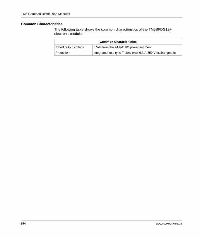
TM5 Common Distribution Modules
Common Characteristics
The following table shows the common characteristics of the TM5SPDG12F electronic module:
Common Characteristics
Rated output voltage 0 Vdc from the 24 Vdc I/O power segment
Protection Integrated fuse type T slow-blow 6.3 A 250 V exchangeable
294 EIO0000000426 04/2012

TM5 Common Distribution Modules
TM5SPDG12F Wiring Diagram
Wiring Diagram
The following figure shows the wiring diagram for the TM5SPDG12F:
1 Internal electronics2 24 Vdc I/O power segment integrated into the bus bases3 Integrated fuse type T slow-blow 6.3 A 250 V exchangeable
NOTE: Common Distribution Modules (CDMs) and the devices they serve must all share the same external power source. That is to say, I/O electronic modules, the field devices connected to them and the CDM must all reside on the same 24 Vdc I/O power segment. If not, the status LEDs may not function correctly. In addition, there may potentially be more significant consequences such as an explosion and/or fire hazard.
WARNINGPOTENTIAL EXPLOSION OR FIRE
Connect the returns from the devices to the same power source as the 24 Vdc I/O power segment serving the module.
Failure to follow these instructions can result in death, serious injury, or equipment damage.
EIO0000000426 04/2012 295
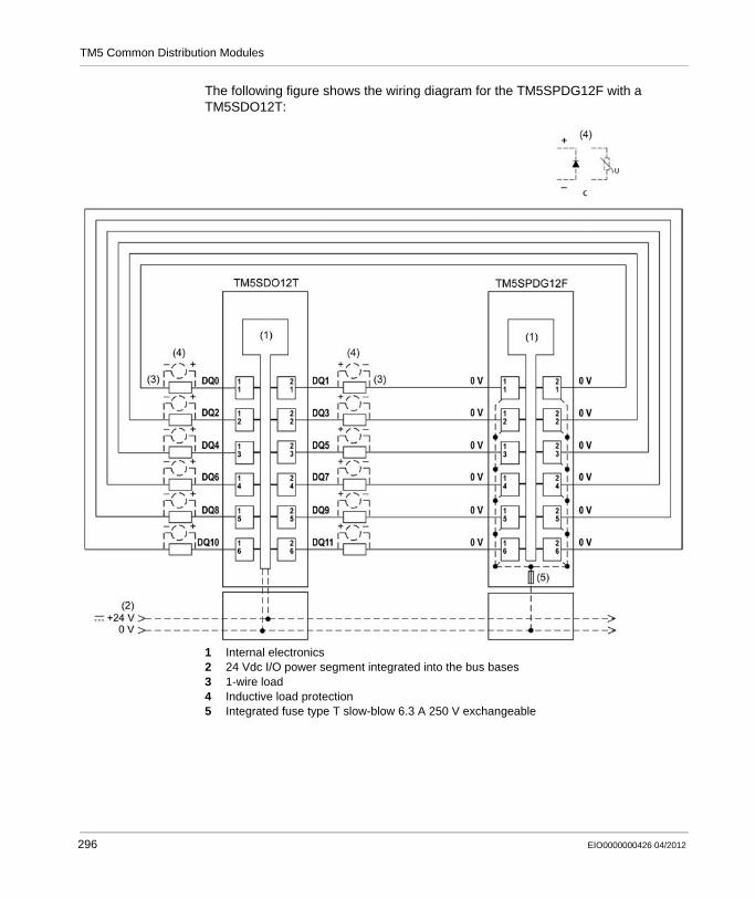
TM5 Common Distribution Modules
The following figure shows the wiring diagram for the TM5SPDG12F with a TM5SDO12T:
1 Internal electronics2 24 Vdc I/O power segment integrated into the bus bases3 1-wire load4 Inductive load protection5 Integrated fuse type T slow-blow 6.3 A 250 V exchangeable
296 EIO0000000426 04/2012

TM5 Common Distribution Modules
WARNINGUNINTENDED EQUIPMENT OPERATION
Do not connect wires to unused terminals or terminals marked “Not Connected (N.C.)”.
Failure to follow these instructions can result in death, serious injury, or equipment damage.
EIO0000000426 04/2012 297
TM5 Common Distribution Modules
C.2 TM5SPDD12F Electronic Module 12 x 24 Vdc
What’s in this Section?
This section contains the following topics:
Topic Page
TM5SPDD12F Presentation 299
TM5SPDD12F Characteristics 301
TM5SPDD12F Wiring Diagram 303
298 EIO0000000426 04/2012
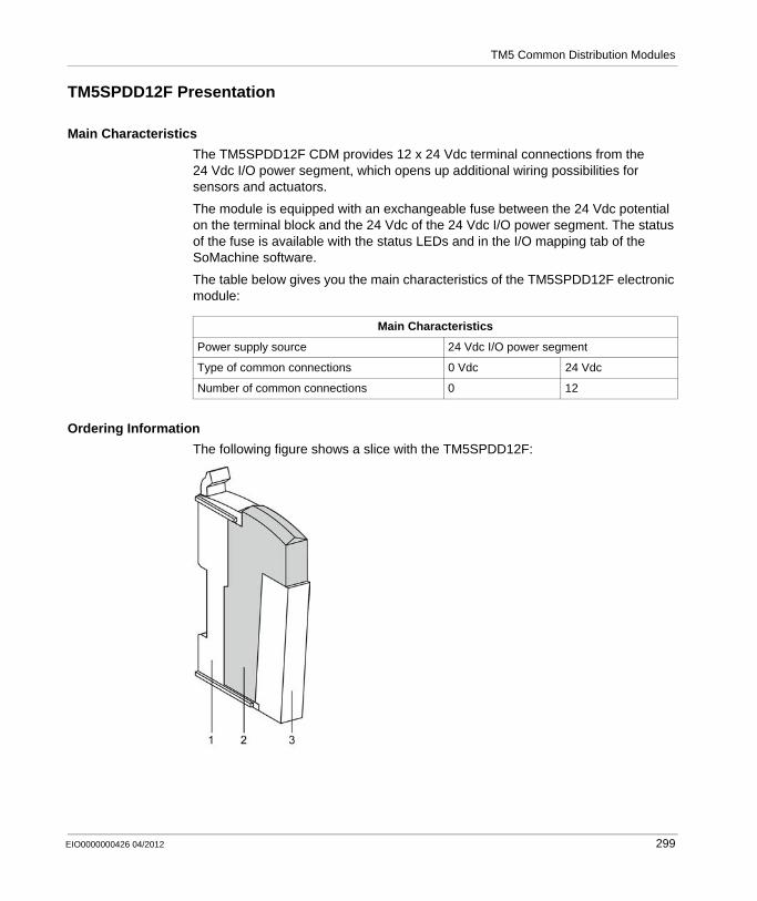
TM5 Common Distribution Modules
TM5SPDD12F Presentation
Main Characteristics
The TM5SPDD12F CDM provides 12 x 24 Vdc terminal connections from the 24 Vdc I/O power segment, which opens up additional wiring possibilities for sensors and actuators.
The module is equipped with an exchangeable fuse between the 24 Vdc potential on the terminal block and the 24 Vdc of the 24 Vdc I/O power segment. The status of the fuse is available with the status LEDs and in the I/O mapping tab of the SoMachine software.
The table below gives you the main characteristics of the TM5SPDD12F electronic module:
Ordering Information
The following figure shows a slice with the TM5SPDD12F:
Main Characteristics
Power supply source 24 Vdc I/O power segment
Type of common connections 0 Vdc 24 Vdc
Number of common connections 0 12
EIO0000000426 04/2012 299

TM5 Common Distribution Modules
NOTE: For more information, refer to TM5 Bus Bases and Terminal Blocks (see page 321).
Status LEDs
The following figure shows the TM5SPDD12F status LEDs:
The table below describes the TM5SPDD12F status LEDs:
Number Model Number Description Color
1TM5ACBM11or TM5ACBM15
Bus base
Bus base with address setting
White
White
2 TM5SPDD12F Electronic module White
3 TM5ACTB12 Terminal block, 12-pin White
LEDs Color Status Description
r Green Off Module supply not connected
Single flash
Reset state
Flashing Preoperational state
On RUN state
e Red Off Ok or no power supply
On Detected error or reset state
Single Flash
Fuse is blown or missing
e+r Steady red / single green flash
Invalid firmware
300 EIO0000000426 04/2012

TM5 Common Distribution Modules
TM5SPDD12F Characteristics
Introduction
This section gives the TM5SPDD12F module characteristics.
See also Environmental Characteristics (see page 68).
General Characteristics
The following table shows the general characteristics of the TM5SPDD12F electronic module:
DANGERFIRE HAZARD
Use only the recommended wire sizes for I/O channels and power supplies.
Failure to follow these instructions will result in death or serious injury.
WARNINGUNINTENDED EQUIPMENT OPERATION
Do not exceed any of the rated values specified in the following tables.
Failure to follow these instructions can result in death, serious injury, or equipment damage.
General Characteristics
Rated power supply voltagePower supply source
24 VdcConnected to the 24 Vdc of the 24 Vdc I/O power segment.
Status indicators Operating state, module status
24 Vdc I/O power segment current draw 6300 mA max.
TM5 power bus 5 Vdc current draw 24 mA
Power dissipation 1.12 W max.
Weight 25 g (0.9 oz)
ID code 9854 dec
EIO0000000426 04/2012 301

TM5 Common Distribution Modules
Common Characteristics
The following table shows the common characteristics of the TM5SPDD12F electronic module:
Common Characteristics
Rated output voltage 24 Vdc from the 24 Vdc I/O power segment
Protection Integrated fuse type T slow-blow 6.3 A 250 V exchangeable
302 EIO0000000426 04/2012

TM5 Common Distribution Modules
TM5SPDD12F Wiring Diagram
Wiring Diagram
The following figure shows the wiring diagram for the TM5SPDD12F:
1 Internal electronics2 24 Vdc I/O power segment integrated into the bus bases3 Integrated fuse type T slow-blow 6.3 A 250 V exchangeable
NOTE: Common Distribution Modules (CDMs) and the devices they serve must all share the same external power source. That is to say, I/O electronic modules, the field devices connected to them and the CDM must all reside on the same 24 Vdc I/O power segment. If not, the status LEDs may not function correctly. In addition, there may potentially be more significant consequences such as an explosion and/or fire hazard.
WARNINGPOTENTIAL EXPLOSION OR FIRE
Connect the returns from the devices to the same power source as the 24 Vdc I/O power segment serving the module.
Failure to follow these instructions can result in death, serious injury, or equipment damage.
EIO0000000426 04/2012 303
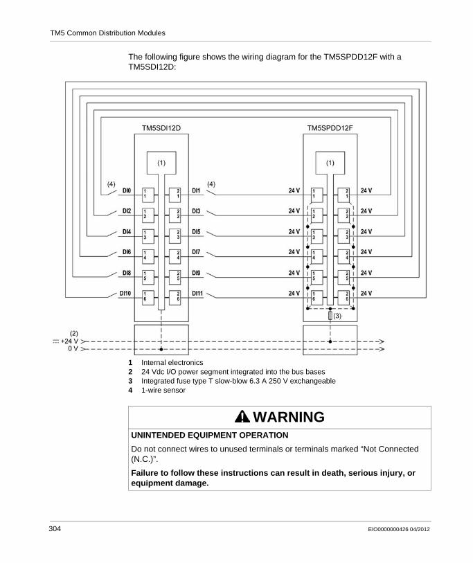
TM5 Common Distribution Modules
The following figure shows the wiring diagram for the TM5SPDD12F with a TM5SDI12D:
1 Internal electronics2 24 Vdc I/O power segment integrated into the bus bases3 Integrated fuse type T slow-blow 6.3 A 250 V exchangeable4 1-wire sensor
WARNINGUNINTENDED EQUIPMENT OPERATION
Do not connect wires to unused terminals or terminals marked “Not Connected (N.C.)”.
Failure to follow these instructions can result in death, serious injury, or equipment damage.
304 EIO0000000426 04/2012
TM5 Common Distribution Modules
C.3 TM5SPDG5D4F Electronic Module 5 x 0 Vdc and 5 x 24 Vdc
What’s in this Section?
This section contains the following topics:
Topic Page
TM5SPDG5D4F Presentation 306
TM5SPDG5D4F Characteristics 308
TM5SPDG5D4F Wiring Diagram 310
EIO0000000426 04/2012 305
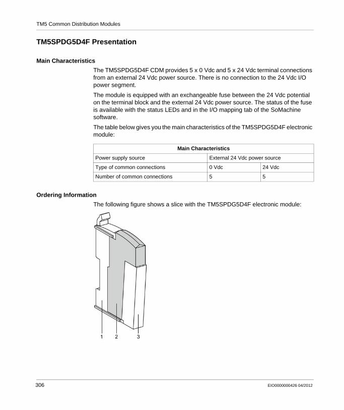
TM5 Common Distribution Modules
TM5SPDG5D4F Presentation
Main Characteristics
The TM5SPDG5D4F CDM provides 5 x 0 Vdc and 5 x 24 Vdc terminal connections from an external 24 Vdc power source. There is no connection to the 24 Vdc I/O power segment.
The module is equipped with an exchangeable fuse between the 24 Vdc potential on the terminal block and the external 24 Vdc power source. The status of the fuse is available with the status LEDs and in the I/O mapping tab of the SoMachine software.
The table below gives you the main characteristics of the TM5SPDG5D4F electronic module:
Ordering Information
The following figure shows a slice with the TM5SPDG5D4F electronic module:
Main Characteristics
Power supply source External 24 Vdc power source
Type of common connections 0 Vdc 24 Vdc
Number of common connections 5 5
306 EIO0000000426 04/2012
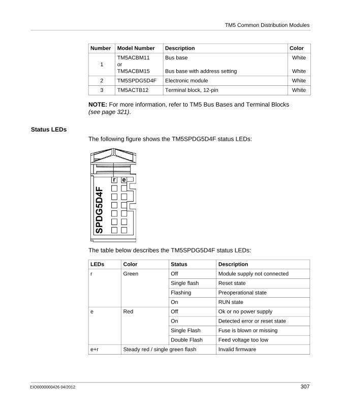
TM5 Common Distribution Modules
NOTE: For more information, refer to TM5 Bus Bases and Terminal Blocks (see page 321).
Status LEDs
The following figure shows the TM5SPDG5D4F status LEDs:
The table below describes the TM5SPDG5D4F status LEDs:
Number Model Number Description Color
1TM5ACBM11or TM5ACBM15
Bus base
Bus base with address setting
White
White
2 TM5SPDG5D4F Electronic module White
3 TM5ACTB12 Terminal block, 12-pin White
LEDs Color Status Description
r Green Off Module supply not connected
Single flash Reset state
Flashing Preoperational state
On RUN state
e Red Off Ok or no power supply
On Detected error or reset state
Single Flash Fuse is blown or missing
Double Flash Feed voltage too low
e+r Steady red / single green flash Invalid firmware
EIO0000000426 04/2012 307
TM5 Common Distribution Modules
TM5SPDG5D4F Characteristics
Introduction
This section gives the TM5SPDG5D4F module characteristics.
See also Environmental Characteristics (see page 68).
General Characteristics
The following table shows the general characteristics of the TM5SPDG5D4F electronic module:
DANGERFIRE HAZARD
Use only the recommended wire sizes for I/O channels and power supplies.
Failure to follow these instructions will result in death or serious injury.
WARNINGUNINTENDED EQUIPMENT OPERATION
Do not exceed any of the rated values specified in the following tables.
Failure to follow these instructions can result in death, serious injury, or equipment damage.
General Characteristics
Rated power supply voltagePower supply source
24 VdcConnected to an external 24 Vdc power source
Power supply range 20.4...28.8 Vdc
Status indicators Operating state, module status
24 Vdc I/O power segment current draw Not connected
TM5 power bus 5 Vdc current draw 24 mA
Power dissipation 1.27 W max.
Weight 25 g (0.9 oz)
ID code 9856 dec
308 EIO0000000426 04/2012

TM5 Common Distribution Modules
Common Characteristics
The following table shows the common characteristics of the TM5SPDG5D4F electronic module:
Common Characteristics
Power supply range 20.4...28.8 Vdc
Rated output voltage 0 Vdc and 24 Vdc from the external 24 Vdc power source
Protection Integrated fuse type T slow-blow 6.3 A 250 V exchangeable
EIO0000000426 04/2012 309
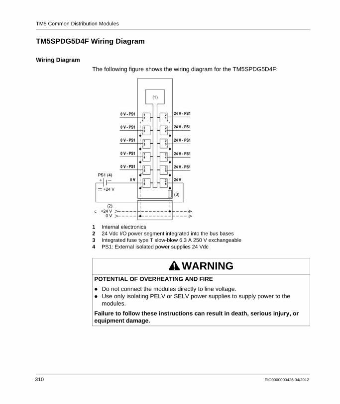
TM5 Common Distribution Modules
TM5SPDG5D4F Wiring Diagram
Wiring Diagram
The following figure shows the wiring diagram for the TM5SPDG5D4F:
1 Internal electronics2 24 Vdc I/O power segment integrated into the bus bases3 Integrated fuse type T slow-blow 6.3 A 250 V exchangeable4 PS1: External isolated power supplies 24 Vdc
WARNINGPOTENTIAL OF OVERHEATING AND FIRE
Do not connect the modules directly to line voltage.Use only isolating PELV or SELV power supplies to supply power to the modules.
Failure to follow these instructions can result in death, serious injury, or equipment damage.
310 EIO0000000426 04/2012
TM5 Common Distribution Modules
WARNINGUNINTENDED EQUIPMENT OPERATION
Do not connect wires to unused terminals or terminals marked “Not Connected (N.C.)”.
Failure to follow these instructions can result in death, serious injury, or equipment damage.
EIO0000000426 04/2012 311

TM5 Common Distribution Modules
C.4 TM5SPDG6D6F Electronic Module 6 x 0 Vdc and 6 x 24 Vdc
What’s in this Section?
This section contains the following topics:
Topic Page
TM5SPDG6D6F Presentation 313
TM5SPDG6D6F Characteristics 315
TM5SPDG6D6F Wiring Diagram 317
312 EIO0000000426 04/2012
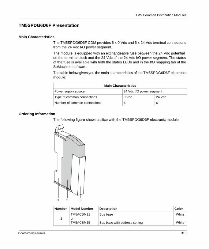
TM5 Common Distribution Modules
TM5SPDG6D6F Presentation
Main Characteristics
The TM5SPDG6D6F CDM provides 6 x 0 Vdc and 6 x 24 Vdc terminal connections from the 24 Vdc I/O power segment.
The module is equipped with an exchangeable fuse between the 24 Vdc potential on the terminal block and the 24 Vdc of the 24 Vdc I/O power segment. The status of the fuse is available with both the status LEDs and in the I/O mapping tab of the SoMachine software.
The table below gives you the main characteristics of the TM5SPDG6D6F electronic module:
Ordering Information
The following figure shows a slice with the TM5SPDG6D6F electronic module:
Main Characteristics
Power supply source 24 Vdc I/O power segment
Type of common connections 0 Vdc 24 Vdc
Number of common connections 6 6
Number Model Number Description Color
1TM5ACBM11or TM5ACBM15
Bus base
Bus base with address setting
White
White
EIO0000000426 04/2012 313
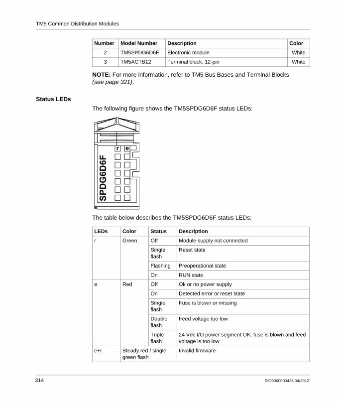
TM5 Common Distribution Modules
NOTE: For more information, refer to TM5 Bus Bases and Terminal Blocks (see page 321).
Status LEDs
The following figure shows the TM5SPDG6D6F status LEDs:
The table below describes the TM5SPDG6D6F status LEDs:
2 TM5SPDG6D6F Electronic module White
3 TM5ACTB12 Terminal block, 12-pin White
Number Model Number Description Color
LEDs Color Status Description
r Green Off Module supply not connected
Single flash
Reset state
Flashing Preoperational state
On RUN state
e Red Off Ok or no power supply
On Detected error or reset state
Single flash
Fuse is blown or missing
Double flash
Feed voltage too low
Triple flash
24 Vdc I/O power segment OK, fuse is blown and feed voltage is too low
e+r Steady red / single green flash
Invalid firmware
314 EIO0000000426 04/2012

TM5 Common Distribution Modules
TM5SPDG6D6F Characteristics
Introduction
This section gives the TM5SPDG6D6F module characteristics.
See also Environmental Characteristics (see page 68).
General Characteristics
The following table shows the general characteristics of the TM5SPDG6D6F electronic module:
DANGERFIRE HAZARD
Use only the recommended wire sizes for I/O channels and power supplies.
Failure to follow these instructions will result in death or serious injury.
WARNINGUNINTENDED EQUIPMENT OPERATION
Do not exceed any of the rated values specified in the following tables.
Failure to follow these instructions can result in death, serious injury, or equipment damage.
General Characteristics
Rated power supply voltagePower supply source
0 Vdc and 24 VdcConnected to the 24 Vdc I/O power segment.
Status indicators Operating state, module status
24 Vdc I/O power segment current draw 6300 mA max.
TM5 power bus 5 Vdc current draw 24 mA
Power dissipation 1.27 W max.
Weight 25 g (0.9 oz)
ID code 9855 dec
EIO0000000426 04/2012 315
TM5 Common Distribution Modules
Common Characteristics
The following table shows the common characteristics of the TM5SPDG6D6F electronic module:
Common Characteristics
Rated output voltage 0 Vdc and 24 Vdc from the 24 Vdc I/O power segment
Protection Integrated fuse type T slow-blow 6.3 A 250 V exchangeable
316 EIO0000000426 04/2012
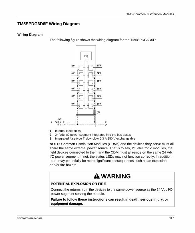
TM5 Common Distribution Modules
TM5SPDG6D6F Wiring Diagram
Wiring Diagram
The following figure shows the wiring diagram for the TM5SPDG6D6F:
1 Internal electronics2 24 Vdc I/O power segment integrated into the bus bases3 Integrated fuse type T slow-blow 6.3 A 250 V exchangeable
NOTE: Common Distribution Modules (CDMs) and the devices they serve must all share the same external power source. That is to say, I/O electronic modules, the field devices connected to them and the CDM must all reside on the same 24 Vdc I/O power segment. If not, the status LEDs may not function correctly. In addition, there may potentially be more significant consequences such as an explosion and/or fire hazard.
WARNINGPOTENTIAL EXPLOSION OR FIRE
Connect the returns from the devices to the same power source as the 24 Vdc I/O power segment serving the module.
Failure to follow these instructions can result in death, serious injury, or equipment damage.
EIO0000000426 04/2012 317

TM5 Common Distribution Modules
The following figure shows the wiring diagram for the TM5SPDG6D6F with a TM5SDI6D:
1 Internal electronics2 24 Vdc I/O power segment integrated into the bus bases3 2-wire sensor4 3-wire sensor5 Integrated fuse type T slow-blow 6.3 A 250 V exchangeable
WARNINGUNINTENDED EQUIPMENT OPERATION
Do not connect wires to unused terminals or terminals marked “Not Connected (N.C.)”.
Failure to follow these instructions can result in death, serious injury, or equipment damage.
318 EIO0000000426 04/2012

EIO0000000426 04/2012
D
Modicon TM5 / TM7 Flexible System
Accessories Modules
EIO0000000426 04/2012
TM5 Accessories Modules
TM5SD000 Dummy Module
General Information
TM5SD000 dummy module is a non-functional module. This module is used as a place holder for later system expansion according to the TM5 association table (see page 242).
Ordering Information
The following figure shows a slice with the TM5SD000 dummy module:
319
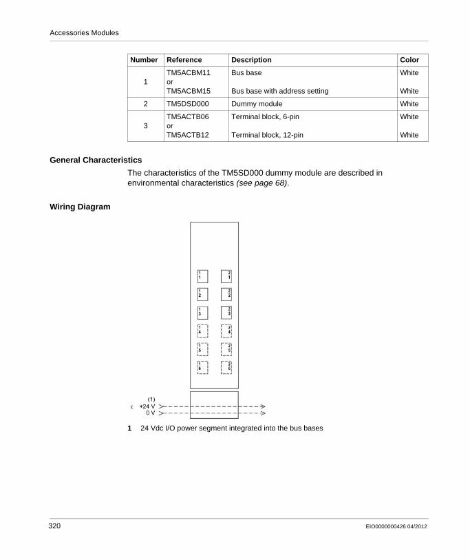
Accessories Modules
General Characteristics
The characteristics of the TM5SD000 dummy module are described in environmental characteristics (see page 68).
Wiring Diagram
1 24 Vdc I/O power segment integrated into the bus bases
Number Reference Description Color
1TM5ACBM11orTM5ACBM15
Bus base
Bus base with address setting
White
White
2 TM5DSD000 Dummy module White
3TM5ACTB06orTM5ACTB12
Terminal block, 6-pin
Terminal block, 12-pin
White
White
320 EIO0000000426 04/2012
EIO0000000426 04/2012
E
Modicon TM5 / TM7 Flexible System
TM5 Bus Bases and Terminal Blocks
EIO0000000426 04/2012
TM5 Bus Bases and Terminal Blocks
Overview
This chapter describes the bus bases and terminal blocks for designing your TM5 System.
What’s in this Chapter?
This chapter contains the following topics:
Topic Page
TM5 Bus Bases 322
TM5 Terminal Blocks 325
321
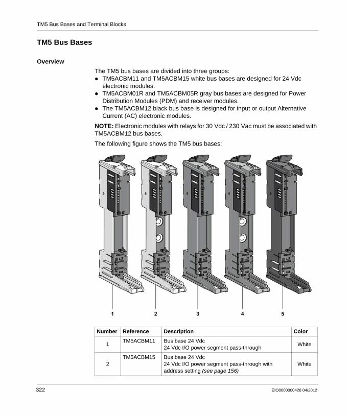
TM5 Bus Bases and Terminal Blocks
TM5 Bus Bases
Overview
The TM5 bus bases are divided into three groups:TM5ACBM11 and TM5ACBM15 white bus bases are designed for 24 Vdc electronic modules.TM5ACBM01R and TM5ACBM05R gray bus bases are designed for Power Distribution Modules (PDM) and receiver modules.The TM5ACBM12 black bus base is designed for input or output Alternative Current (AC) electronic modules.
NOTE: Electronic modules with relays for 30 Vdc / 230 Vac must be associated with TM5ACBM12 bus bases.
The following figure shows the TM5 bus bases:
Number Reference Description Color
1TM5ACBM11 Bus base 24 Vdc
24 Vdc I/O power segment pass-throughWhite
2TM5ACBM15 Bus base 24 Vdc
24 Vdc I/O power segment pass-through with address setting (see page 156)
White
322 EIO0000000426 04/2012
TM5 Bus Bases and Terminal Blocks
A slice must only be composed of a single color. For example, a gray bus base should only be assembled with a gray electronic module and a gray terminal block. However, color alone is not sufficient for compatibility; always confirm that functionality of slice components matches as well.
General Characteristics
This section gives the TM5 bus bases characteristics. See also environmental characteristics (see page 68).
3TM5ACBM01R Bus base 24 Vdc for PDM and Receiver modules
24 Vdc I/O power segment left isolatedGray
4TM5ACBM05R Bus base 24 Vdc for PDM and Receiver modules
24 Vdc I/O power segment left isolated with address setting (see page 156)
Gray
5TM5ACBM12 Bus base for AC modules
24 Vdc I/O power segment pass throughBlack
DANGERINCOMPATIBLE COMPONENTS CAUSE ELECTRONIC SHOCK OR ARC FLASH
Do not associate components of a slice that have different colors.Always confirm the compatibility of slice components and modules before installation using the association table in this manual.Ensure that a correct terminal block is installed on the appropriate electronic module.
Failure to follow these instructions will result in death or serious injury.
Number Reference Description Color
WARNINGUNINTENDED EQUIPMENT OPERATION
Do not exceed any of the rated values specified in the following tables.
Failure to follow these instructions can result in death, serious injury, or equipment damage.
EIO0000000426 04/2012 323

TM5 Bus Bases and Terminal Blocks
The following table shows the technical data for TM5 bus bases:
General Characteristics
TM5 power bus current draw 26 mA
Power dissipation 0.13 W max.
Weight 20 g (0.7 oz)
324 EIO0000000426 04/2012
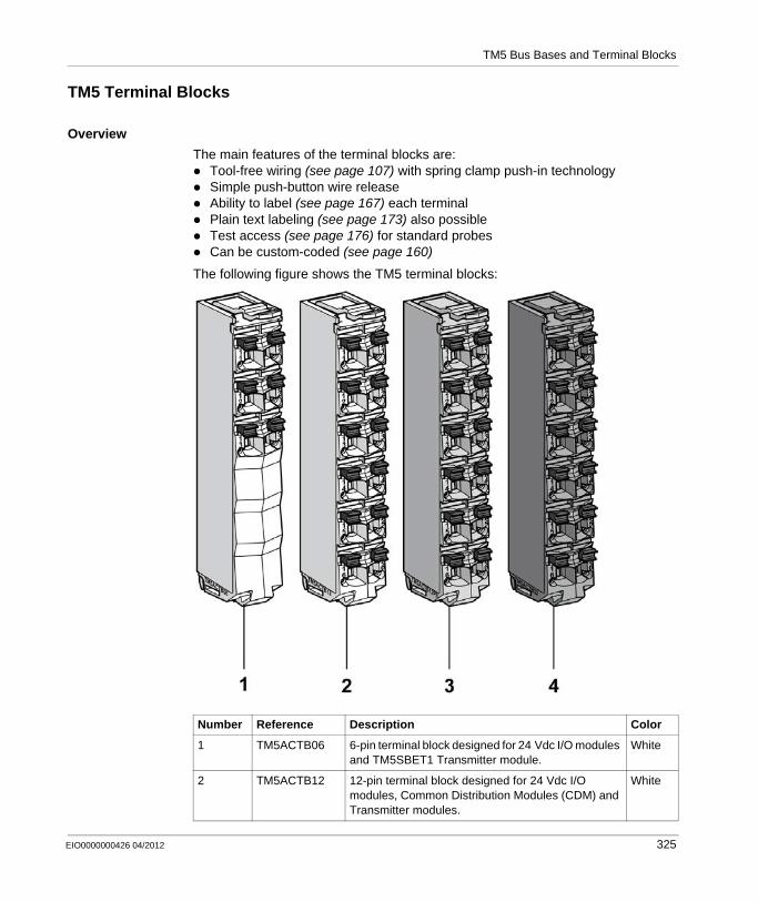
TM5 Bus Bases and Terminal Blocks
TM5 Terminal Blocks
Overview
The main features of the terminal blocks are:Tool-free wiring (see page 107) with spring clamp push-in technologySimple push-button wire releaseAbility to label (see page 167) each terminalPlain text labeling (see page 173) also possibleTest access (see page 176) for standard probesCan be custom-coded (see page 160)
The following figure shows the TM5 terminal blocks:
Number Reference Description Color
1 TM5ACTB06 6-pin terminal block designed for 24 Vdc I/O modules and TM5SBET1 Transmitter module.
White
2 TM5ACTB12 12-pin terminal block designed for 24 Vdc I/O modules, Common Distribution Modules (CDM) and Transmitter modules.
White
EIO0000000426 04/2012 325
TM5 Bus Bases and Terminal Blocks
A slice must only be composed of a single color. For example, a gray bus base should only be assembled with a gray electronic module and a gray terminal block. However, color alone is not sufficient for compatibility; always confirm that functionality of slice components matches as well.
General Characteristics
3 TM5ACTB12PS 12-pin terminal block designed for 24 Vdc Power Distribution Modules (PDM), 24 Vdc Interface Power distribution Module (IPDM) and Receiver module.
Gray
4 TM5ACTB32 12-pin terminal block designed for AC and I/O relays modules.
Black
DANGERINCOMPATIBLE COMPONENTS CAUSE ELECTRONIC SHOCK OR ARC FLASH
Do not associate components of a slice that have different colors.Always confirm the compatibility of slice components and modules before installation using the association table in this manual.Ensure that a correct terminal block is installed on the appropriate electronic module.
Failure to follow these instructions will result in death or serious injury.
Number Reference Description Color
DANGERFIRE HAZARD
Use only the recommended wire sizes for I/O channels and power supplies.
Failure to follow these instructions will result in death or serious injury.
WARNINGUNINTENDED EQUIPMENT OPERATION
Do not exceed any of the rated values specified in the following tables.
Failure to follow these instructions can result in death, serious injury, or equipment damage.
326 EIO0000000426 04/2012
TM5 Bus Bases and Terminal Blocks
The following table shows the technical data for TM5 terminal blocks, see also environmental characteristics (see page 68):
WARNINGUNINTENDED EQUIPMENT OPERATION
Do not connect wires to unused terminals or terminals marked “Not Connected (N.C.)”.
Failure to follow these instructions can result in death, serious injury, or equipment damage.
General Characteristics
Type of terminal Spring-clamp push-in terminal
Contact resistance ≤ 5 mΩ
Maximum voltage1 300 V
Current1 10 A max. per connector
Weight TM5ACTB06 16 g (0.6 oz)
TM5ACTB12TM5ACTB12PSTM5ACTB32
20 g (0.7 oz)
Connection cross section:Solid wire lineFine wire lineWith wire cable endWith double wire cable end
0.08 mm²...2.5 mm² (AWG 28...14)0.25 mm²...2.5 mm² (AWG 24...14)0.25 mm²...1.5 mm² (AWG 24...16)2 x 0.25...2 x 0.75 mm² (AWG 2 x 24...2 x 18)
Wire Follow the wiring rules (see page 107).
Note:1 Connected voltage and current depends on I/O electronics modules associated.
DANGERLOOSE WIRING CAUSES ELECTRIC SHOCK
Do not insert more than one wire per connector of the terminal block without a double wire cable end.
Failure to follow these instructions will result in death or serious injury.
EIO0000000426 04/2012 327

TM5 Bus Bases and Terminal Blocks
Maximum Insertion/Removal Cycles
The TM5 bus bases are designed to withstand up to 50 electronic module insertion/removal cycles.
NOTE: If electronic modules are inserted and removed from a bus base more than 50 times, the integrity of the electronic module-to-bus base contacts will be subject to possible degradation. Be sure the history of your electronic modules is known.
328 EIO0000000426 04/2012
EIO0000000426 04/2012
F
Modicon TM5 / TM7 Flexible System
Power Distribution Block (PDB)
EIO0000000426 04/2012
TM7 Power Distribution Block (PDB)
Overview
This chapter describes the TM7SPS1A Power Distribution Block (PDB) for designing your TM7 System.
What’s in this Chapter?
This chapter contains the following topics:
Topic Page
TM7SPS1A Presentation 330
TM7SPS1A Characteristics 332
TM7SPS1A Wiring Diagram 334
329

Power Distribution Block (PDB)
TM7SPS1A Presentation
Main Characteristics
The TM7SPS1A PDB supplies the TM7 power bus.
The following table provides the main characteristics of the TM7SPS1A block:
Description
The following figure illustrates the TM7SPS1A block:
(A) TM7 bus IN connector(B) TM7 bus OUT connector(C) 24 Vdc power IN connector(D) 24 Vdc power OUT connector(1) Status LEDs
NOTE: Refer also to Status LEDs (see page 331).
Main Characteristics
Rated output power 15 W
Rated input voltage 24 Vdc
Rated output voltage 20 Vdc
Rated output current 750 mA
TM7 bus connection type M12, B coded, male and female connector types
Power supply connection type
M8, 4-pin, male and female connector types
330 EIO0000000426 04/2012
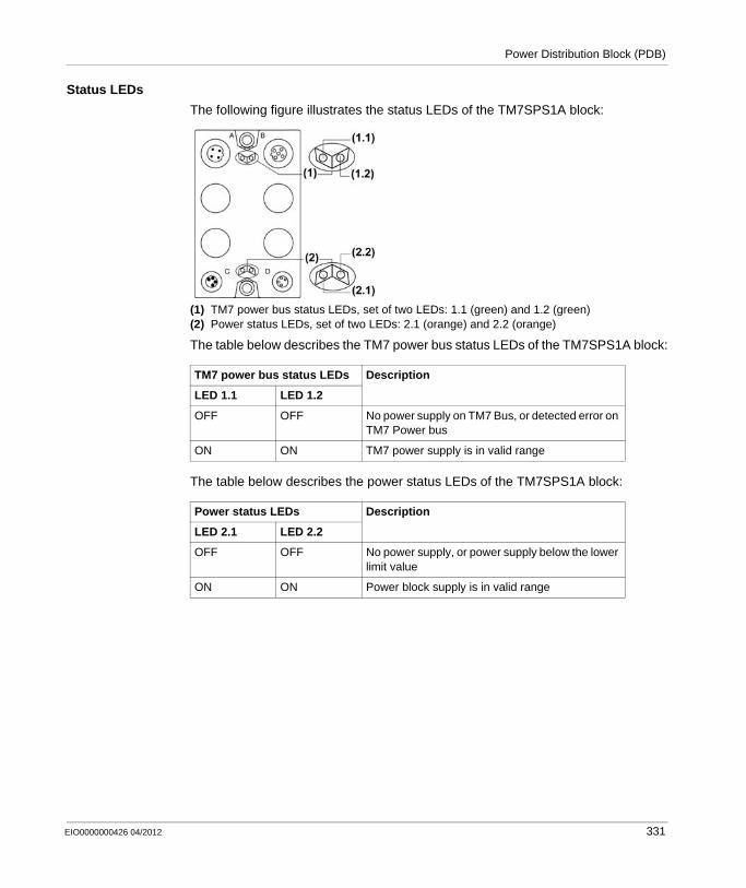
Power Distribution Block (PDB)
Status LEDs
The following figure illustrates the status LEDs of the TM7SPS1A block:
(1) TM7 power bus status LEDs, set of two LEDs: 1.1 (green) and 1.2 (green)(2) Power status LEDs, set of two LEDs: 2.1 (orange) and 2.2 (orange)
The table below describes the TM7 power bus status LEDs of the TM7SPS1A block:
The table below describes the power status LEDs of the TM7SPS1A block:
TM7 power bus status LEDs Description
LED 1.1 LED 1.2
OFF OFF No power supply on TM7 Bus, or detected error on TM7 Power bus
ON ON TM7 power supply is in valid range
Power status LEDs Description
LED 2.1 LED 2.2
OFF OFF No power supply, or power supply below the lower limit value
ON ON Power block supply is in valid range
EIO0000000426 04/2012 331
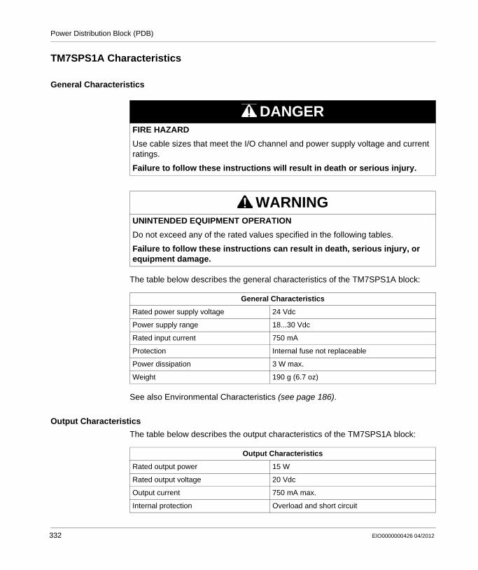
Power Distribution Block (PDB)
TM7SPS1A Characteristics
General Characteristics
The table below describes the general characteristics of the TM7SPS1A block:
See also Environmental Characteristics (see page 186).
Output Characteristics
The table below describes the output characteristics of the TM7SPS1A block:
DANGERFIRE HAZARD
Use cable sizes that meet the I/O channel and power supply voltage and current ratings.
Failure to follow these instructions will result in death or serious injury.
WARNINGUNINTENDED EQUIPMENT OPERATION
Do not exceed any of the rated values specified in the following tables.
Failure to follow these instructions can result in death, serious injury, or equipment damage.
General Characteristics
Rated power supply voltage 24 Vdc
Power supply range 18...30 Vdc
Rated input current 750 mA
Protection Internal fuse not replaceable
Power dissipation 3 W max.
Weight 190 g (6.7 oz)
Output Characteristics
Rated output power 15 W
Rated output voltage 20 Vdc
Output current 750 mA max.
Internal protection Overload and short circuit
332 EIO0000000426 04/2012
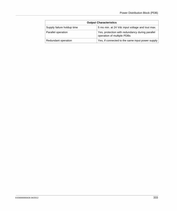
Power Distribution Block (PDB)
Supply failure holdup time 5 ms min. at 24 Vdc input voltage and Iout max.
Parallel operation Yes, protection with redundancy during parallel operation of multiple PDBs
Redundant operation Yes, if connected to the same input power supply
Output Characteristics
EIO0000000426 04/2012 333

Power Distribution Block (PDB)
TM7SPS1A Wiring Diagram
Pin Assignments
The following figure shows the pin assignment of the TM7 bus IN (A) and OUT (B) connectors:
The following figure shows the pin assignment of the 24 Vdc power IN (C) and OUT (D) connectors:
Use shielded, properly grounded cables for all analog and high-speed inputs or outputs and communication connections. If you do not use shielded cable for these connections, electromagnetic interference can cause signal degradation. Degraded signals can cause the controller or attached modules and equipment to perform in an unintended manner.
Connector (A) Pin Designation Connector (B)
1 TM7 V+
2 TM7 Bus Data
3 TM7 0V
4 TM7 Bus Data
5 N.C.
Connector (C) Pin Designation Connector (D)
1 24 Vdc Main power
2 24 Vdc Main power
3 0 Vdc
4 0 Vdc
DANGERFIRE HAZARD
Use cable sizes that meet the I/O channel and power supply voltage and current ratings.
Failure to follow these instructions will result in death or serious injury.
1
23
4 4
32
15
12
3
4
12
3
4
334 EIO0000000426 04/2012
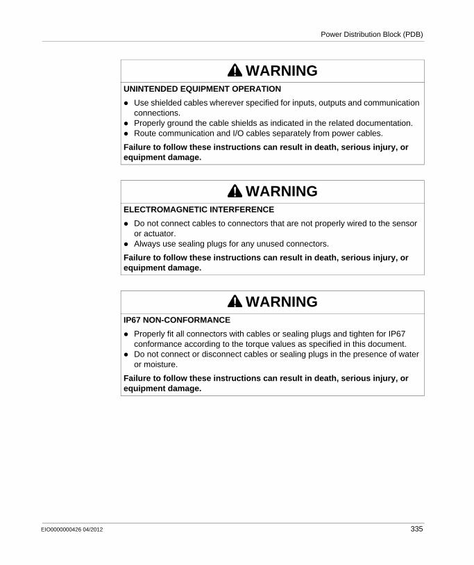
Power Distribution Block (PDB)
WARNINGUNINTENDED EQUIPMENT OPERATION
Use shielded cables wherever specified for inputs, outputs and communication connections.Properly ground the cable shields as indicated in the related documentation.Route communication and I/O cables separately from power cables.
Failure to follow these instructions can result in death, serious injury, or equipment damage.
WARNINGELECTROMAGNETIC INTERFERENCE
Do not connect cables to connectors that are not properly wired to the sensor or actuator.Always use sealing plugs for any unused connectors.
Failure to follow these instructions can result in death, serious injury, or equipment damage.
WARNINGIP67 NON-CONFORMANCE
Properly fit all connectors with cables or sealing plugs and tighten for IP67 conformance according to the torque values as specified in this document.Do not connect or disconnect cables or sealing plugs in the presence of water or moisture.
Failure to follow these instructions can result in death, serious injury, or equipment damage.
EIO0000000426 04/2012 335

Power Distribution Block (PDB)
336 EIO0000000426 04/2012
EIO0000000426 04/2012
G
Modicon TM5 / TM7 Flexible System
TM7 Cables
EIO0000000426 04/2012
TM7 Cables
Overview
This chapter describes the TM7 cables for wiring your TM7 System.
What’s in this Chapter?
This chapter contains the following topics:
Topic Page
Expansion Bus Cables 338
CANopen Cables 346
Power Cables 354
Sensor Cables 361
337

TM7 Cables
Expansion Bus Cables
Overview
The following figure shows expansion bus cables used in TM5/TM7 configurations:
1 Attachment IN cable: to connect a TM7 I/O block after a TM5 configuration using a TM5SBET7 transmitter module.
2 Drop cable: to build TM7 expansion bus between TM7 expansions blocks.3 Attachment OUT cable: to connect a TM5 remote island after a TM7 I/O block using a
TM5SBER2 receiver module.
338 EIO0000000426 04/2012
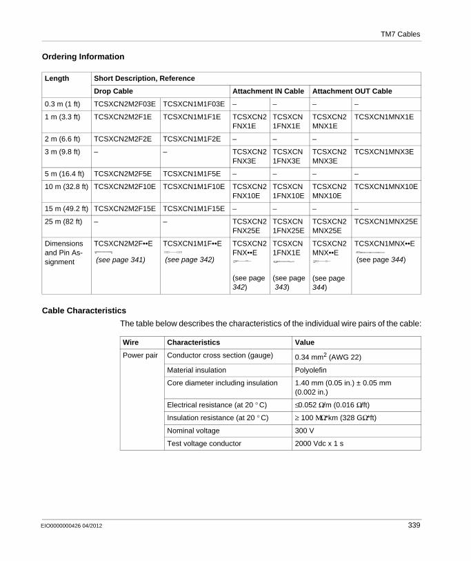
TM7 Cables
Ordering Information
Cable Characteristics
The table below describes the characteristics of the individual wire pairs of the cable:
Length Short Description, Reference
Drop Cable Attachment IN Cable Attachment OUT Cable
0.3 m (1 ft) TCSXCN2M2F03E TCSXCN1M1F03E – – – –
1 m (3.3 ft) TCSXCN2M2F1E TCSXCN1M1F1E TCSXCN2FNX1E
TCSXCN1FNX1E
TCSXCN2MNX1E
TCSXCN1MNX1E
2 m (6.6 ft) TCSXCN2M2F2E TCSXCN1M1F2E – – – –
3 m (9.8 ft) – – TCSXCN2FNX3E
TCSXCN1FNX3E
TCSXCN2MNX3E
TCSXCN1MNX3E
5 m (16.4 ft) TCSXCN2M2F5E TCSXCN1M1F5E – – – –
10 m (32.8 ft) TCSXCN2M2F10E TCSXCN1M1F10E TCSXCN2FNX10E
TCSXCN1FNX10E
TCSXCN2MNX10E
TCSXCN1MNX10E
15 m (49.2 ft) TCSXCN2M2F15E TCSXCN1M1F15E – – – –
25 m (82 ft) – – TCSXCN2FNX25E
TCSXCN1FNX25E
TCSXCN2MNX25E
TCSXCN1MNX25E
Dimensions and Pin As-signment
TCSXCN2M2F••E
(see page 341)
TCSXCN1M1F••E
(see page 342)
TCSXCN2FNX••E
(see page342)
TCSXCN1FNX1E
(see page343)
TCSXCN2MNX••E
(see page344)
TCSXCN1MNX••E
(see page 344)
Wire Characteristics Value
Power pair Conductor cross section (gauge) 0.34 mm2 (AWG 22)
Material insulation Polyolefin
Core diameter including insulation 1.40 mm (0.05 in.) ± 0.05 mm (0.002 in.)
Electrical resistance (at 20 ° C) ≤0.052 Ω/m (0.016 Ω/ft)
Insulation resistance (at 20 ° C) ≥ 100 ΜΩ*km (328 GΩ*ft)
Nominal voltage 300 V
Test voltage conductor 2000 Vdc x 1 s
EIO0000000426 04/2012 339

TM7 Cables
The table below describes the general characteristics of the cable:
The table below describes the environmental characteristics of the cable:
Data pair Conductor cross section (gauge) 0.2 mm2 (AWG 24)
Material insulation Foam-skin PE
Core diameter including insulation 2.05 mm (0.08 in.) ± 0.1 mm (0.004 in.)
Electrical resistance (at 20 ° C) ≤0.078 Ω/m (0.024 Ω/ft)
Insulation resistance (at 20 ° C) ≥ 5000 ΜΩ*km (16.4 TΩ*ft)
Characteristic impedance (at 5 MHz) 120 Ω
Nominal voltage 30 V
Test voltage conductor 1500 Vdc x 1 s
Characteristics Specification
Cable type Special PUR black shielded
Conductor material Stranded tinned copper
Shield Tinned copper foil and drain wire
External cable diameter 6.7 mm (0.26 in.) ± 0.3 mm (0.012 in.)
Minimum curve radius 67 mm (2.63 in.)
Max pulling strength Static application 50 N/mm2 (7252 lbf/in2)
Dynamic application 20 N/mm2 (2901 lbf/in2)
Wire colors Power pair Red, black
Data pair Blue, white
External sheath, color Black-gray RAL 7021
Cable weight 54.8 kg/km (0.037 lb/ft)
Number of bending cycles 4 million
Traversing path 10 m (32.8 ft)
Traversing rate 3 m/s (9.8 ft/s)
Acceleration 10 m/s2 (32.8 ft/s2)
M12 fastening torque Max 0.4 N.m (3.5 lbf-in)
Characteristics Specification
Operating temperature –20...75 ° C (–4...167 ° F)
Storage temperature –40...80 ° C (–40...176 ° F)
Wire Characteristics Value
340 EIO0000000426 04/2012

TM7 Cables
TCSXCN2M2F••E Dimensions and Pin Assignment
Special properties Flexible cable conduit capable
Silicone-free
Freedom from halogen As per DIN VDE 0472 part 815
WEEE/RoHS Compliant
Characteristics Specification
Dimensions
L length as a function of the particular reference
Pin Assignment
Male Connector Pin Designation Wire Color Female Connector
1 TM7 V+ Red
2 TM7 Bus Data White
3 TM7 OV Black
4 TM7 Bus Data Blue
M121 SHLD Shield
1 Shielding 360 ° around M12 knurled screw.
ø0.58ø14,8
in.mm
1.4336,3
1.4336,3
L
ø0.58ø14,7
1.10281.21
30,8
1
23
4 4
32
1
EIO0000000426 04/2012 341
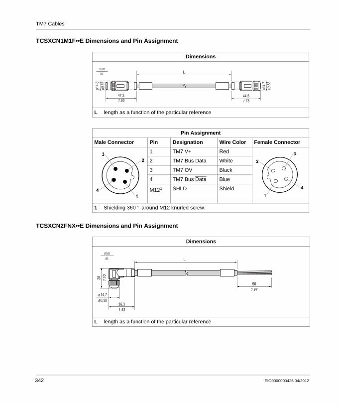
TM7 Cables
TCSXCN1M1F••E Dimensions and Pin Assignment
TCSXCN2FNX••E Dimensions and Pin Assignment
Dimensions
L length as a function of the particular reference
Pin Assignment
Male Connector Pin Designation Wire Color Female Connector
1 TM7 V+ Red
2 TM7 Bus Data White
3 TM7 OV Black
4 TM7 Bus Data Blue
M121 SHLD Shield
1 Shielding 360 ° around M12 knurled screw.
ø14,8
ø0.5
8
47,31.86
mmin. L
ø14,7
ø0.5
8
44,51.75
1
23
4 4
32
1
Dimensions
L length as a function of the particular reference
ø0.58ø14,7
in.mm
1.4336,3
1.9750
L
1.1028
342 EIO0000000426 04/2012
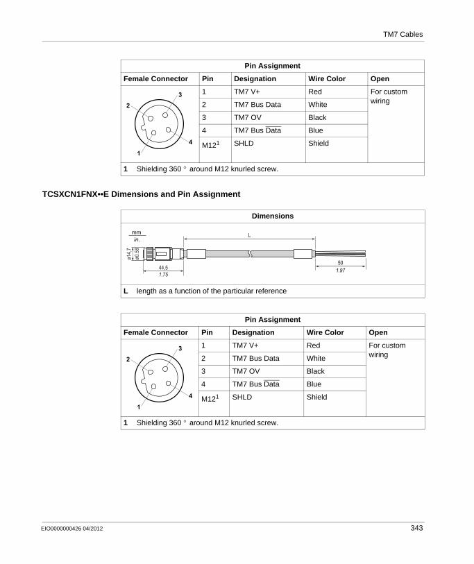
TM7 Cables
TCSXCN1FNX••E Dimensions and Pin Assignment
Pin Assignment
Female Connector Pin Designation Wire Color Open
1 TM7 V+ Red For custom wiring2 TM7 Bus Data White
3 TM7 OV Black
4 TM7 Bus Data Blue
M121 SHLD Shield
1 Shielding 360 ° around M12 knurled screw.
4
32
1
Dimensions
L length as a function of the particular reference
Pin Assignment
Female Connector Pin Designation Wire Color Open
1 TM7 V+ Red For custom wiring2 TM7 Bus Data White
3 TM7 OV Black
4 TM7 Bus Data Blue
M121 SHLD Shield
1 Shielding 360 ° around M12 knurled screw.
1.9750
L
ø14,7
ø0.5
8
44,51.75
in.mm
4
32
1
EIO0000000426 04/2012 343
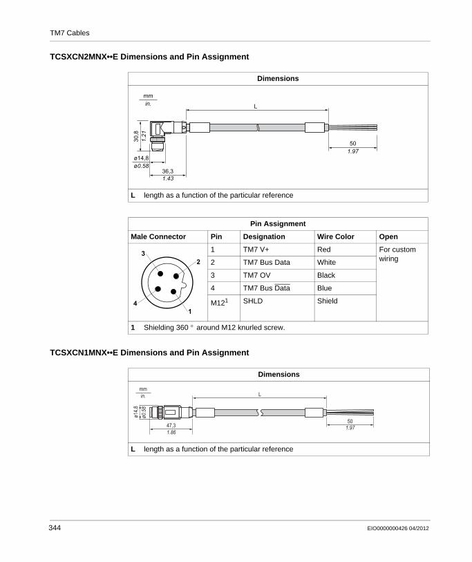
TM7 Cables
TCSXCN2MNX••E Dimensions and Pin Assignment
TCSXCN1MNX••E Dimensions and Pin Assignment
Dimensions
L length as a function of the particular reference
Pin Assignment
Male Connector Pin Designation Wire Color Open
1 TM7 V+ Red For custom wiring2 TM7 Bus Data White
3 TM7 OV Black
4 TM7 Bus Data Blue
M121 SHLD Shield
1 Shielding 360 ° around M12 knurled screw.
ø0.58ø14,8
in.mm
1.4336,3
L
1.21
30,8
1.9750
1
23
4
Dimensions
L length as a function of the particular reference
ø14,8
ø0.5
8
47,31.86
mmin. L
501.97
344 EIO0000000426 04/2012
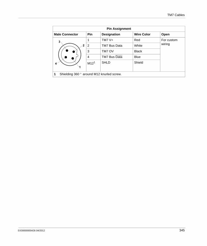
TM7 Cables
Pin Assignment
Male Connector Pin Designation Wire Color Open
1 TM7 V+ Red For custom wiring2 TM7 Bus Data White
3 TM7 OV Black
4 TM7 Bus Data Blue
M121 SHLD Shield
1 Shielding 360 ° around M12 knurled screw.
1
23
4
EIO0000000426 04/2012 345

TM7 Cables
CANopen Cables
Overview
The following figure shows an example of TM5/TM7 configuration using CANopen cables:
1 Attachment IN cable: to connect a TM7 CANopen interface I/O block to an IP20 configuration (controller, TM5 CANopen island, or other IP20 CANopen devices).
2 Drop cable: to build CAN bus between TM7 CANopen interface I/O blocks.3 Attachment OUT cable: to connect a TM5 CANopen island or other IP20 CANopen device
to a TM7 CANopen interface I/O block.4 CAN bus Y cable5 CAN bus Y connector6 M12 CAN bus terminating resistor
346 EIO0000000426 04/2012
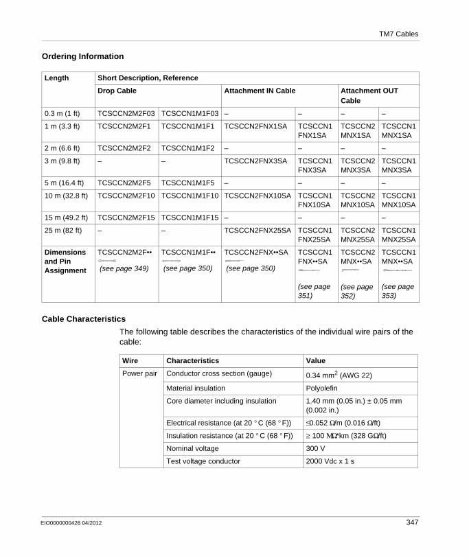
TM7 Cables
Ordering Information
Cable Characteristics
The following table describes the characteristics of the individual wire pairs of the cable:
Length Short Description, Reference
Drop Cable Attachment IN Cable Attachment OUT Cable
0.3 m (1 ft) TCSCCN2M2F03 TCSCCN1M1F03 – – – –
1 m (3.3 ft) TCSCCN2M2F1 TCSCCN1M1F1 TCSCCN2FNX1SA TCSCCN1FNX1SA
TCSCCN2MNX1SA
TCSCCN1MNX1SA
2 m (6.6 ft) TCSCCN2M2F2 TCSCCN1M1F2 – – – –
3 m (9.8 ft) – – TCSCCN2FNX3SA TCSCCN1FNX3SA
TCSCCN2MNX3SA
TCSCCN1MNX3SA
5 m (16.4 ft) TCSCCN2M2F5 TCSCCN1M1F5 – – – –
10 m (32.8 ft) TCSCCN2M2F10 TCSCCN1M1F10 TCSCCN2FNX10SA TCSCCN1FNX10SA
TCSCCN2MNX10SA
TCSCCN1MNX10SA
15 m (49.2 ft) TCSCCN2M2F15 TCSCCN1M1F15 – – – –
25 m (82 ft) – – TCSCCN2FNX25SA TCSCCN1FNX25SA
TCSCCN2MNX25SA
TCSCCN1MNX25SA
Dimensions and Pin Assignment
TCSCCN2M2F••
(see page 349)
TCSCCN1M1F••
(see page 350)
TCSCCN2FNX••SA
(see page 350)
TCSCCN1FNX••SA
(see page351)
TCSCCN2MNX••SA
(see page352)
TCSCCN1MNX••SA
(see page353)
Wire Characteristics Value
Power pair Conductor cross section (gauge) 0.34 mm2 (AWG 22)
Material insulation Polyolefin
Core diameter including insulation 1.40 mm (0.05 in.) ± 0.05 mm (0.002 in.)
Electrical resistance (at 20 ° C (68 ° F)) ≤0.052 Ω/m (0.016 Ω/ft)
Insulation resistance (at 20 ° C (68 ° F)) ≥ 100 ΜΩ*km (328 GΩ/ft)
Nominal voltage 300 V
Test voltage conductor 2000 Vdc x 1 s
EIO0000000426 04/2012 347
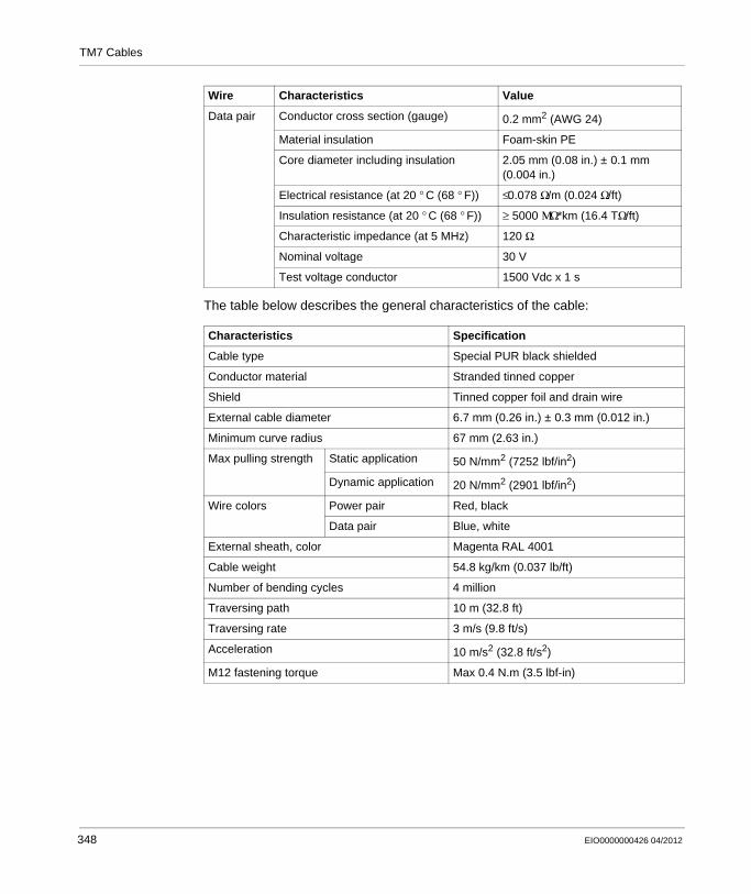
TM7 Cables
The table below describes the general characteristics of the cable:
Data pair Conductor cross section (gauge) 0.2 mm2 (AWG 24)
Material insulation Foam-skin PE
Core diameter including insulation 2.05 mm (0.08 in.) ± 0.1 mm (0.004 in.)
Electrical resistance (at 20 ° C (68 ° F)) ≤0.078 Ω/m (0.024 Ω/ft)
Insulation resistance (at 20 ° C (68 ° F)) ≥ 5000 ΜΩ*km (16.4 TΩ/ft)
Characteristic impedance (at 5 MHz) 120 Ω
Nominal voltage 30 V
Test voltage conductor 1500 Vdc x 1 s
Characteristics Specification
Cable type Special PUR black shielded
Conductor material Stranded tinned copper
Shield Tinned copper foil and drain wire
External cable diameter 6.7 mm (0.26 in.) ± 0.3 mm (0.012 in.)
Minimum curve radius 67 mm (2.63 in.)
Max pulling strength Static application 50 N/mm2 (7252 lbf/in2)
Dynamic application 20 N/mm2 (2901 lbf/in2)
Wire colors Power pair Red, black
Data pair Blue, white
External sheath, color Magenta RAL 4001
Cable weight 54.8 kg/km (0.037 lb/ft)
Number of bending cycles 4 million
Traversing path 10 m (32.8 ft)
Traversing rate 3 m/s (9.8 ft/s)
Acceleration 10 m/s2 (32.8 ft/s2)
M12 fastening torque Max 0.4 N.m (3.5 lbf-in)
Wire Characteristics Value
348 EIO0000000426 04/2012
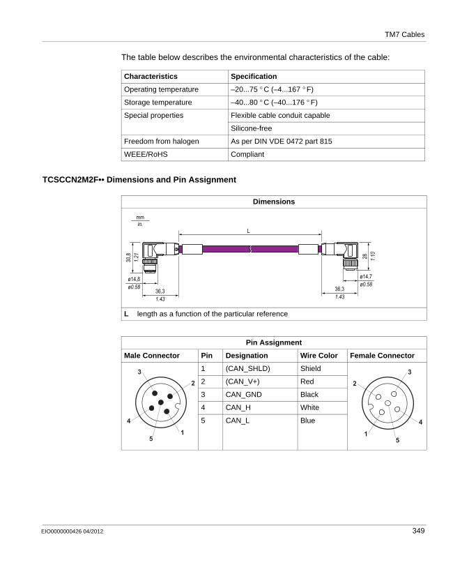
TM7 Cables
The table below describes the environmental characteristics of the cable:
TCSCCN2M2F•• Dimensions and Pin Assignment
Characteristics Specification
Operating temperature –20...75 ° C (–4...167 ° F)
Storage temperature –40...80 ° C (–40...176 ° F)
Special properties Flexible cable conduit capable
Silicone-free
Freedom from halogen As per DIN VDE 0472 part 815
WEEE/RoHS Compliant
Dimensions
L length as a function of the particular reference
Pin Assignment
Male Connector Pin Designation Wire Color Female Connector
1 (CAN_SHLD) Shield
2 (CAN_V+) Red
3 CAN_GND Black
4 CAN_H White
5 CAN_L Blue
ø0.58ø14,8
in.mm
1.4336,3
1.4336,3
L
ø0.58ø14,7
1.10281.2130,8
4
32
15
4
32
15
EIO0000000426 04/2012 349
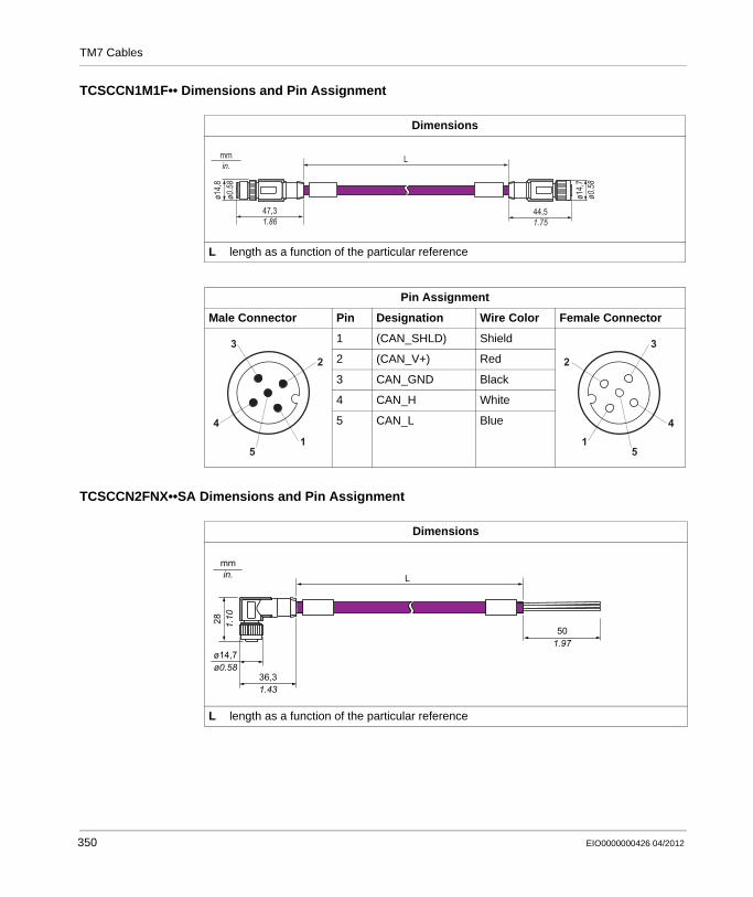
TM7 Cables
TCSCCN1M1F•• Dimensions and Pin Assignment
TCSCCN2FNX••SA Dimensions and Pin Assignment
Dimensions
L length as a function of the particular reference
Pin Assignment
Male Connector Pin Designation Wire Color Female Connector
1 (CAN_SHLD) Shield
2 (CAN_V+) Red
3 CAN_GND Black
4 CAN_H White
5 CAN_L Blue
ø14,8
ø0.5
8
47,31.86
mmin.
L
ø14,7
ø0.5
8
44,51.75
4
32
15
4
32
15
Dimensions
L length as a function of the particular reference
ø0.58ø14,7
in.mm
1.4336,3
1.9750
L
1.1028
350 EIO0000000426 04/2012
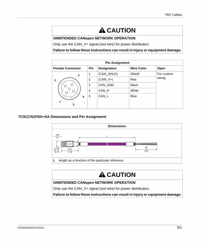
TM7 Cables
TCSCCN1FNX••SA Dimensions and Pin Assignment
CAUTIONUNINTENDED CANopen NETWORK OPERATION
Only use the CAN_V+ signal (red wire) for power distribution.
Failure to follow these instructions can result in injury or equipment damage.
Pin Assignment
Female Connector Pin Designation Wire Color Open
1 (CAN_SHLD) Shield For custom wiring2 (CAN_V+) Red
3 CAN_GND Black
4 CAN_H White
5 CAN_L Blue4
32
15
Dimensions
L length as a function of the particular reference
CAUTIONUNINTENDED CANopen NETWORK OPERATION
Only use the CAN_V+ signal (red wire) for power distribution.
Failure to follow these instructions can result in injury or equipment damage.
1.9750
L
ø14,7
ø0.5
8 44,51.75
in.mm
EIO0000000426 04/2012 351
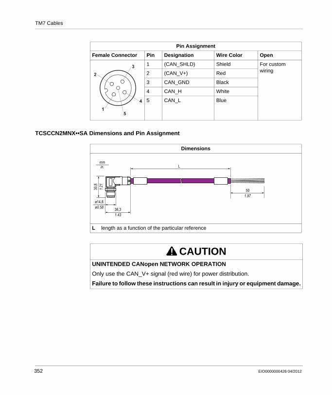
TM7 Cables
TCSCCN2MNX••SA Dimensions and Pin Assignment
Pin Assignment
Female Connector Pin Designation Wire Color Open
1 (CAN_SHLD) Shield For custom wiring2 (CAN_V+) Red
3 CAN_GND Black
4 CAN_H White
5 CAN_L Blue4
32
15
Dimensions
L length as a function of the particular reference
CAUTIONUNINTENDED CANopen NETWORK OPERATION
Only use the CAN_V+ signal (red wire) for power distribution.
Failure to follow these instructions can result in injury or equipment damage.
ø0.58ø14,8
in.mm
1.4336,3
L
1.2130,8
1.9750
352 EIO0000000426 04/2012
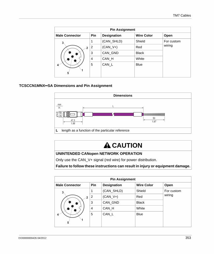
TM7 Cables
TCSCCN1MNX••SA Dimensions and Pin Assignment
Pin Assignment
Male Connector Pin Designation Wire Color Open
1 (CAN_SHLD) Shield For custom wiring2 (CAN_V+) Red
3 CAN_GND Black
4 CAN_H White
5 CAN_L Blue4
32
15
Dimensions
L length as a function of the particular reference
CAUTIONUNINTENDED CANopen NETWORK OPERATION
Only use the CAN_V+ signal (red wire) for power distribution.
Failure to follow these instructions can result in injury or equipment damage.
Pin Assignment
Male Connector Pin Designation Wire Color Open
1 (CAN_SHLD) Shield For custom wiring2 (CAN_V+) Red
3 CAN_GND Black
4 CAN_H White
5 CAN_L Blue
ø14,8
ø0.5
8
47,31.86
mmin. L
1.9750
4
32
15
EIO0000000426 04/2012 353
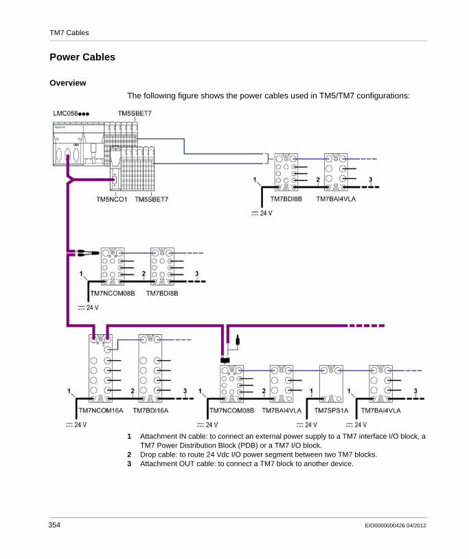
TM7 Cables
Power Cables
Overview
The following figure shows the power cables used in TM5/TM7 configurations:
1 Attachment IN cable: to connect an external power supply to a TM7 interface I/O block, a TM7 Power Distribution Block (PDB) or a TM7 I/O block.
2 Drop cable: to route 24 Vdc I/O power segment between two TM7 blocks.3 Attachment OUT cable: to connect a TM7 block to another device.
354 EIO0000000426 04/2012
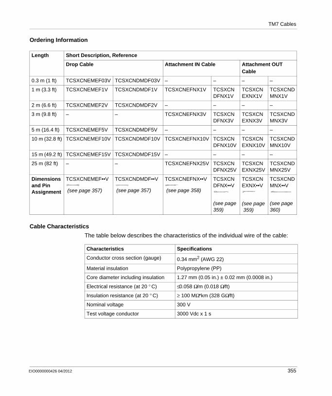
TM7 Cables
Ordering Information
Cable Characteristics
The table below describes the characteristics of the individual wire of the cable:
Length Short Description, Reference
Drop Cable Attachment IN Cable Attachment OUT Cable
0.3 m (1 ft) TCSXCNEMEF03V TCSXCNDMDF03V – – – –
1 m (3.3 ft) TCSXCNEMEF1V TCSXCNDMDF1V TCSXCNEFNX1V TCSXCNDFNX1V
TCSXCNEXNX1V
TCSXCNDMNX1V
2 m (6.6 ft) TCSXCNEMEF2V TCSXCNDMDF2V – – – –
3 m (9.8 ft) – – TCSXCNEFNX3V TCSXCNDFNX3V
TCSXCNEXNX3V
TCSXCNDMNX3V
5 m (16.4 ft) TCSXCNEMEF5V TCSXCNDMDF5V – – – –
10 m (32.8 ft) TCSXCNEMEF10V TCSXCNDMDF10V TCSXCNEFNX10V TCSXCNDFNX10V
TCSXCNEXNX10V
TCSXCNDMNX10V
15 m (49.2 ft) TCSXCNEMEF15V TCSXCNDMDF15V – – – –
25 m (82 ft) – – TCSXCNEFNX25V TCSXCNDFNX25V
TCSXCNEXNX25V
TCSXCNDMNX25V
Dimensions and Pin Assignment
TCSXCNEMEF••V
(see page 357)
TCSXCNDMDF••V
(see page 357)
TCSXCNEFNX••V
(see page 358)
TCSXCNDFNX••V
(see page359)
TCSXCNEXNX••V
(see page359)
TCSXCNDMNX••V
(see page360)
Characteristics Specifications
Conductor cross section (gauge) 0.34 mm2 (AWG 22)
Material insulation Polypropylene (PP)
Core diameter including insulation 1.27 mm (0.05 in.) ± 0.02 mm (0.0008 in.)
Electrical resistance (at 20 ° C) ≤0.058 Ω/m (0.018 Ω/ft)
Insulation resistance (at 20 ° C) ≥ 100 MΩ*km (328 GΩ/ft)
Nominal voltage 300 V
Test voltage conductor 3000 Vdc x 1 s
EIO0000000426 04/2012 355
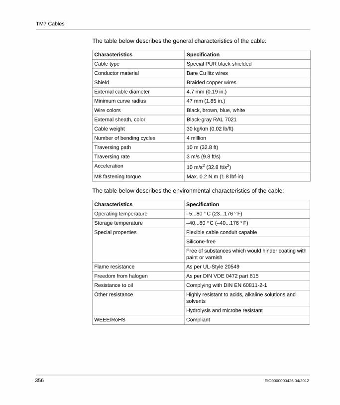
TM7 Cables
The table below describes the general characteristics of the cable:
The table below describes the environmental characteristics of the cable:
Characteristics Specification
Cable type Special PUR black shielded
Conductor material Bare Cu litz wires
Shield Braided copper wires
External cable diameter 4.7 mm (0.19 in.)
Minimum curve radius 47 mm (1.85 in.)
Wire colors Black, brown, blue, white
External sheath, color Black-gray RAL 7021
Cable weight 30 kg/km (0.02 lb/ft)
Number of bending cycles 4 million
Traversing path 10 m (32.8 ft)
Traversing rate 3 m/s (9.8 ft/s)
Acceleration 10 m/s2 (32.8 ft/s2)
M8 fastening torque Max. 0.2 N.m (1.8 lbf-in)
Characteristics Specification
Operating temperature –5...80 ° C (23...176 ° F)
Storage temperature –40...80 ° C (–40...176 ° F)
Special properties Flexible cable conduit capable
Silicone-free
Free of substances which would hinder coating with paint or varnish
Flame resistance As per UL-Style 20549
Freedom from halogen As per DIN VDE 0472 part 815
Resistance to oil Complying with DIN EN 60811-2-1
Other resistance Highly resistant to acids, alkaline solutions and solvents
Hydrolysis and microbe resistant
WEEE/RoHS Compliant
356 EIO0000000426 04/2012
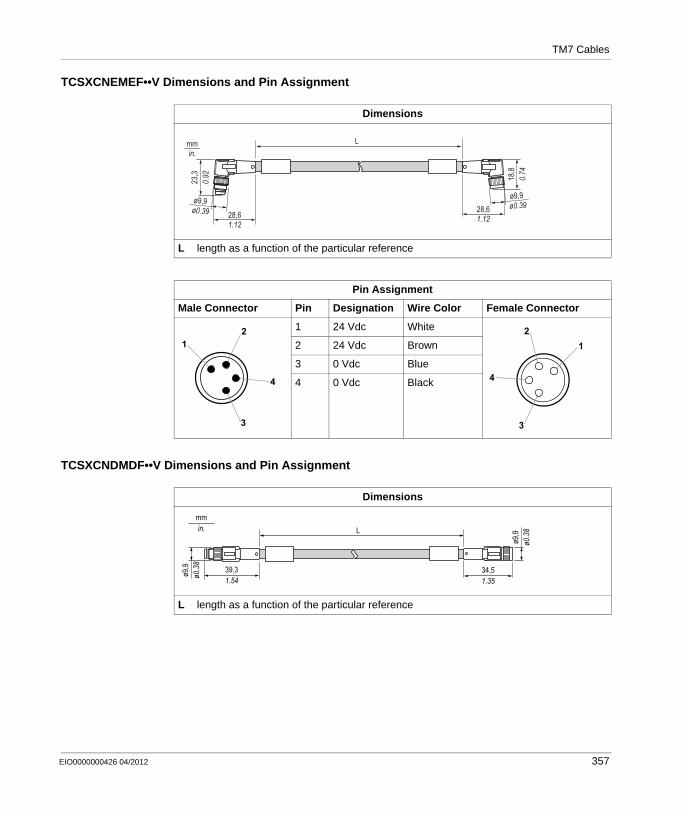
TM7 Cables
TCSXCNEMEF••V Dimensions and Pin Assignment
TCSXCNDMDF••V Dimensions and Pin Assignment
Dimensions
L length as a function of the particular reference
Pin Assignment
Male Connector Pin Designation Wire Color Female Connector
1 24 Vdc White
2 24 Vdc Brown
3 0 Vdc Blue
4 0 Vdc Black
23,3
0.92
mm Lin.
28,61.12
ø9,9ø0.39
18,8
0.74
28,61.12
ø9,9ø0.39
12
3
4
12
3
4
Dimensions
L length as a function of the particular reference
ø0.3
8ø9
,9
in.mm
1.5439,3
L
1.3534,5
ø0.3
8ø9
,9
EIO0000000426 04/2012 357

TM7 Cables
TCSXCNEFNX••V Dimensions and Pin Assignment
Pin Assignment
Male Connector Pin Designation Wire Color Female Connector
1 24 Vdc White
2 24 Vdc Brown
3 0 Vdc Blue
4 0 Vdc Black
12
3
4
12
3
4
Dimensions
L length as a function of the particular reference
Pin Assignment
Female Connector Pin Designation Wire Color Open
1 24 Vdc White For custom wiring2 24 Vdc Brown
3 0 Vdc Blue
4 0 Vdc Black
18,8
0.74
mmin.
28,61.12
L
501.97
ø9,9ø0.39
12
3
4
358 EIO0000000426 04/2012
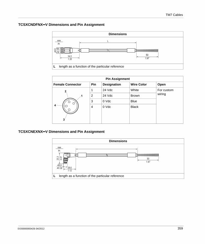
TM7 Cables
TCSXCNDFNX••V Dimensions and Pin Assignment
TCSXCNEXNX••V Dimensions and Pin Assignment
Dimensions
L length as a function of the particular reference
Pin Assignment
Female Connector Pin Designation Wire Color Open
1 24 Vdc White For custom wiring2 24 Vdc Brown
3 0 Vdc Blue
4 0 Vdc Black
1.9750
L
ø9,9
ø0.3
934,51.35
in.mm
12
3
4
Dimensions
L length as a function of the particular reference
23,3
0.91
28,61.12
501.97
ø9,9ø0.39
in.mm
EIO0000000426 04/2012 359
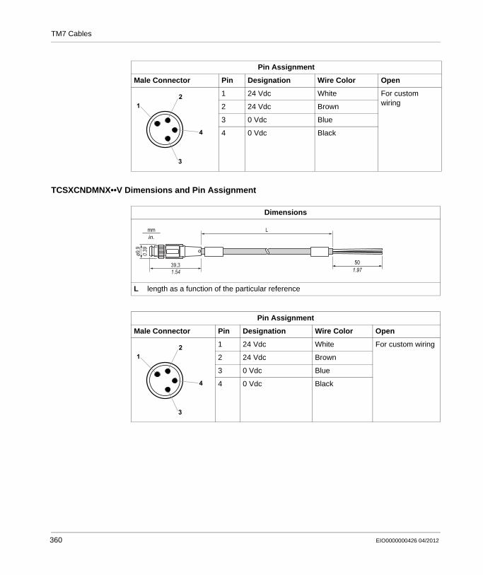
TM7 Cables
TCSXCNDMNX••V Dimensions and Pin Assignment
Pin Assignment
Male Connector Pin Designation Wire Color Open
1 24 Vdc White For custom wiring2 24 Vdc Brown
3 0 Vdc Blue
4 0 Vdc Black
12
3
4
Dimensions
L length as a function of the particular reference
Pin Assignment
Male Connector Pin Designation Wire Color Open
1 24 Vdc White For custom wiring
2 24 Vdc Brown
3 0 Vdc Blue
4 0 Vdc Black
1.9750
L
ø9,9
0.39
39,31.54
in.mm
12
3
4
360 EIO0000000426 04/2012
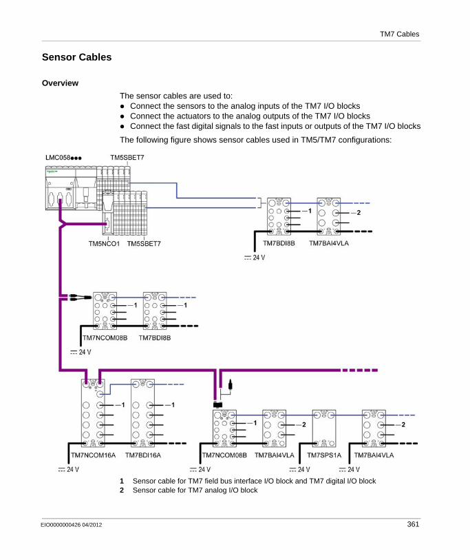
TM7 Cables
Sensor Cables
Overview
The sensor cables are used to:Connect the sensors to the analog inputs of the TM7 I/O blocksConnect the actuators to the analog outputs of the TM7 I/O blocksConnect the fast digital signals to the fast inputs or outputs of the TM7 I/O blocks
The following figure shows sensor cables used in TM5/TM7 configurations:
1 Sensor cable for TM7 field bus interface I/O block and TM7 digital I/O block2 Sensor cable for TM7 analog I/O block
EIO0000000426 04/2012 361
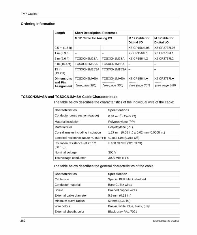
TM7 Cables
Ordering Information
TCSXCN2M••SA and TCSXCN1M••SA Cable Characteristics
The table below describes the characteristics of the individual wire of the cable:
The table below describes the general characteristics of the cable:
Length Short Description, Reference
M 12 Cable for Analog I/O M 12 Cable for Digital I/O
M 8 Cable for Digital I/O
0.5 m (1.6 ft) – – XZ CP1564L05 XZ CP2737L05
1 m (3.3 ft) – – XZ CP1564L1 XZ CP2737L1
2 m (6.6 ft) TCSXCN2M2SA TCSXCN1M2SA XZ CP1564L2 XZ CP2737L2
5 m (16.4 ft) TCSXCN2M5SA TCSXCN1M5SA – –
15 m (49.2 ft)
TCSXCN2M15SA TCSXCN1M15SA – –
Dimensions and Pin Assignment
TCSXCN2M••SA
(see page 366)
TCSXCN1M••SA
(see page 366)
XZ CP1564L••
(see page 367)
XZ CP2737L••
(see page 368)
Characteristics Specifications
Conductor cross section (gauge) 0.34 mm2 (AWG 22)
Material insulation Polypropylene (PP)
Material filler Polyethylene (PE)
Core diameter including insulation 1.27 mm (0.05 in.) ± 0.02 mm (0.0008 in.)
Electrical resistance (at 20 ° C (68 ° F)) ≤0.058 Ω/m (0.018 Ω/ft)
Insulation resistance (at 20 ° C (68 ° F))
≥ 100 GΩ*km (328 TΩ*ft)
Nominal voltage 300 V
Test voltage conductor 3000 Vdc x 1 s
Characteristics Specification
Cable type Special PUR black shielded
Conductor material Bare Cu litz wires
Shield Braided copper wires
External cable diameter 5.9 mm (0.23 in.)
Minimum curve radius 59 mm (2.32 in.)
Wire colors Brown, white, blue, black, gray
External sheath, color Black-gray RAL 7021
362 EIO0000000426 04/2012
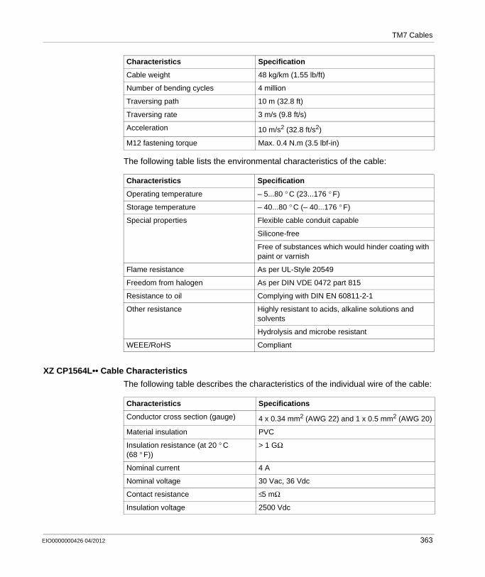
TM7 Cables
The following table lists the environmental characteristics of the cable:
XZ CP1564L•• Cable Characteristics
The following table describes the characteristics of the individual wire of the cable:
Cable weight 48 kg/km (1.55 lb/ft)
Number of bending cycles 4 million
Traversing path 10 m (32.8 ft)
Traversing rate 3 m/s (9.8 ft/s)
Acceleration 10 m/s2 (32.8 ft/s2)
M12 fastening torque Max. 0.4 N.m (3.5 lbf-in)
Characteristics Specification
Operating temperature – 5...80 ° C (23...176 ° F)
Storage temperature – 40...80 ° C (– 40...176 ° F)
Special properties Flexible cable conduit capable
Silicone-free
Free of substances which would hinder coating with paint or varnish
Flame resistance As per UL-Style 20549
Freedom from halogen As per DIN VDE 0472 part 815
Resistance to oil Complying with DIN EN 60811-2-1
Other resistance Highly resistant to acids, alkaline solutions and solvents
Hydrolysis and microbe resistant
WEEE/RoHS Compliant
Characteristics Specification
Characteristics Specifications
Conductor cross section (gauge) 4 x 0.34 mm2 (AWG 22) and 1 x 0.5 mm2 (AWG 20)
Material insulation PVC
Insulation resistance (at 20 ° C (68 ° F))
> 1 GΩ
Nominal current 4 A
Nominal voltage 30 Vac, 36 Vdc
Contact resistance ≤5 mΩ
Insulation voltage 2500 Vdc
EIO0000000426 04/2012 363
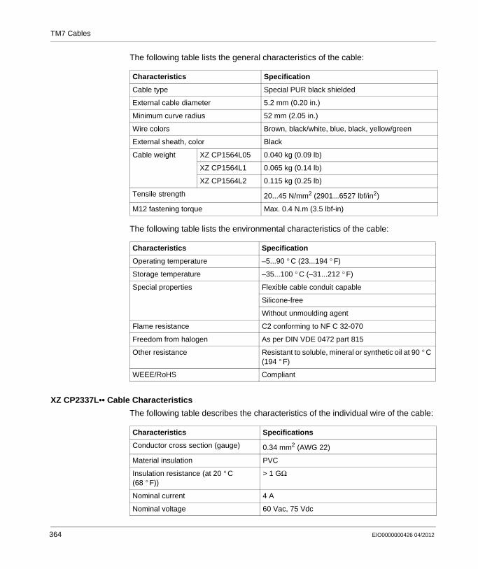
TM7 Cables
The following table lists the general characteristics of the cable:
The following table lists the environmental characteristics of the cable:
XZ CP2337L•• Cable Characteristics
The following table describes the characteristics of the individual wire of the cable:
Characteristics Specification
Cable type Special PUR black shielded
External cable diameter 5.2 mm (0.20 in.)
Minimum curve radius 52 mm (2.05 in.)
Wire colors Brown, black/white, blue, black, yellow/green
External sheath, color Black
Cable weight XZ CP1564L05 0.040 kg (0.09 lb)
XZ CP1564L1 0.065 kg (0.14 lb)
XZ CP1564L2 0.115 kg (0.25 lb)
Tensile strength 20...45 N/mm2 (2901...6527 lbf/in2)
M12 fastening torque Max. 0.4 N.m (3.5 lbf-in)
Characteristics Specification
Operating temperature –5...90 ° C (23...194 ° F)
Storage temperature –35...100 ° C (–31...212 ° F)
Special properties Flexible cable conduit capable
Silicone-free
Without unmoulding agent
Flame resistance C2 conforming to NF C 32-070
Freedom from halogen As per DIN VDE 0472 part 815
Other resistance Resistant to soluble, mineral or synthetic oil at 90 ° C (194 ° F)
WEEE/RoHS Compliant
Characteristics Specifications
Conductor cross section (gauge) 0.34 mm2 (AWG 22)
Material insulation PVC
Insulation resistance (at 20 ° C (68 ° F))
> 1 GΩ
Nominal current 4 A
Nominal voltage 60 Vac, 75 Vdc
364 EIO0000000426 04/2012
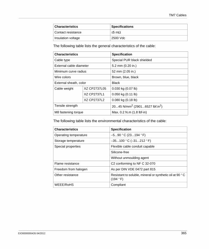
TM7 Cables
The following table lists the general characteristics of the cable:
The following table lists the environmental characteristics of the cable:
Contact resistance ≤5 mΩ
Insulation voltage 2500 Vdc
Characteristics Specification
Cable type Special PUR black shielded
External cable diameter 5.2 mm (0.20 in.)
Minimum curve radius 52 mm (2.05 in.)
Wire colors Brown, blue, black
External sheath, color Black
Cable weight XZ CP2737L05 0.030 kg (0.07 lb)
XZ CP2737L1 0.050 kg (0.11 lb)
XZ CP2737L2 0.080 kg (0.18 lb)
Tensile strength 20...45 N/mm2 (2901...6527 lbf.in2)
M8 fastening torque Max. 0.2 N.m (1.8 lbf-in)
Characteristics Specification
Operating temperature –5...90 ° C (23...194 ° F)
Storage temperature –35...100 ° C (–31...212 ° F)
Special properties Flexible cable conduit capable
Silicone-free
Without unmoulding agent
Flame resistance C2 conforming to NF C 32-070
Freedom from halogen As per DIN VDE 0472 part 815
Other resistance Resistant to soluble, mineral or synthetic oil at 90 ° C (194 ° F)
WEEE/RoHS Compliant
Characteristics Specifications
EIO0000000426 04/2012 365

TM7 Cables
TCSXCN2M••SA Dimensions and Pin Assignment
TCSXCN1M••SA Dimensions and Pin Assignment
Dimensions
L length as a function of the particular reference
Pin Assignment
Male Connector Pin Designation Wire Color
1 For pin assignment, refer to the wiring diagrams of the Modicon TM7 Analog I/O Blocks Hardware Guide.
Brown
2 White
3 Blue
4 Black
5 Gray
M121 SHLD
1 Shielding 360 ° around M12 knurled screw
ø0.58ø14,8
in.mm
1.4336,3
L
1.21
30,8
1.9750
4
32
15
Dimensions
L length as a function of the particular reference
ø14,8
ø0.5
8
47,31.86
mmin. L
501.97
366 EIO0000000426 04/2012

TM7 Cables
XZ CP1564L•• Dimensions and Pin Assignment
Pin Assignment
Male Connector Pin Designation Wire Color
1 For pin assignment, refer to the wiring diagrams of the Modicon TM7 Analog I/O Blocks Hardware Guide.
Brown
2 White
3 Blue
4 Black
5 Gray
M121 SHLD
1 Shielding 360 ° around M12 knurled screw
4
32
15
Dimensions
L length as a function of the particular reference
Pin Assignment
Male Connector Pin Designation Wire Color
1 For pin assignment, refer to the wiring diagrams of the Modicon TM7 Digital I/O Blocks Hardware Guide or Modicon TM7 CANopen I/O Blocks Hardware Guide.
Brown
2 Black / White
3 Blue
4 Black
5 Yellow / Green
L
M12
ø11
ø0.4
346,81.84
mmin.
ø14,8
ø0.5
8
4
32
15
EIO0000000426 04/2012 367
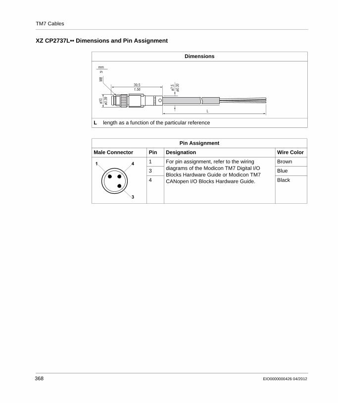
TM7 Cables
XZ CP2737L•• Dimensions and Pin Assignment
Dimensions
L length as a function of the particular reference
Pin Assignment
Male Connector Pin Designation Wire Color
1 For pin assignment, refer to the wiring diagrams of the Modicon TM7 Digital I/O Blocks Hardware Guide or Modicon TM7 CANopen I/O Blocks Hardware Guide.
Brown
3 Blue
4 Black
L
39,51.56
ø10
ø0.39
M8
ø7,5
ø0.30
mmin.
1 4
3
368 EIO0000000426 04/2012
Modicon TM5 / TM7 Flexible System
Glossary
EIO0000000426 04/2012
Glossary
A
analog inputAn analog input module contains circuits that convert an analog DC input signal to a digital value that can be manipulated by the processor. By implication, the analog input is usually direct. That means a data table value directly reflects the analog signal value.
analog outputAn analog output module contains circuits that transmit an analog DC signal proportional to a digital value input to the module from the processor. By implication, these analog outputs are usually direct. That means a data table value directly controls the analog signal value.
AWGThe american wire gauge standard specifies wire gauges in North America.
B
bus baseA bus base is a mounting device that is designed to seat an electronic module on a DIN rail and connect it to the TM5 bus for M258 and LMC058 controllers. Each base bus extends the TM5 data and to the power buses and the 24 Vdc I/O power segment. The electronic modules are added to the TM5 system through their insertion on the base bus. The base bus also supplies the articulation point for the terminal blocks.
EIO0000000426 04/2012 369
Glossary
C
CANThe controller area network protocol (ISO 11898) for serial bus networks is designed for the interconnection of smart devices (from multiple manufacturers) in smart systems for real-time industrial applications. CAN multimaster systems help ensure high data integrity through the implementation of broadcast messaging and advanced diagnostic mechanisms. Originally developed for use in automobiles, CAN is now used in a variety of industrial automation control environments.
CANopenCANopen is an open industry-standard communication protocol and device profile specification.
compact I/O moduleA compact I/O module is an indissociable group of five analog and/or digital I/O electronic modules in a single reference.
configurationThe configuration includes the arrangement and interconnection of hardware components within a system and the hardware and software selections that determine the operating characteristics of the system.
controllerA controller (or “programmable logic controller,” or “programmable controller”) is used to automate industrial processes.
CPDMcontroller power distribution module
CSAThe canadian standards association defines and maintains standards for industrial electronic equipment in hazardous environments.
CTSClear to send is a data transmission signal and acknowledges the RDS signal from the transmitting station.
370 EIO0000000426 04/2012
Glossary
D
De-ratingDe-rating describes a reduction in an operating specification. For devices in general it is usually a specified reduction in nominal power to facilitate operation at increased ambient conditions like higher temperatures or higher altitudes.
DHCPThe dynamic host configuration protocol is an advanced extension of BOOTP. DHCP is a more advanced, but both DHCP and BOOTP are common. (DHCP can handle BOOTP client requests.)
digital I/OA digital input or output has an individual circuit connection at the electronic module that corresponds directly to a data table bit that holds the value of the signal at that I/O circuit. It gives the control logic digital access to I/O values.
DINDeutsches Institut für Normung is a German institution that sets engineering and dimensional standards.
E
electronic moduleIn a programmable controller system, most electronic modules directly interface to the sensors, actuators, and external devices of the machine/process. This electronic module is the component that mounts in a bus base and provides electrical connections between the controller and the field devices. Electronic modules are offered in a variety of signal levels and capacities. (Some electronic modules are not I/O interfaces, including power distribution modules and transmitter/receiver modules.)
ENEN identifies one of many European standards maintained by CEN (European Committee for Standardization), CENELEC (European Committee for Electrotechnical Standardization), or ETSI (European Telecommunications Standards Institute).
EIO0000000426 04/2012 371

Glossary
encoderAn encoder is a device for length or angular measurement (linear or rotary encoders).
EthernetEthernet is a physical and data link layer technology for LANs, also known as IEE 802.3.
expansion busThe expansion bus is an electronic communication bus between expansion modules and a CPU.
expert I/OExpert I/Os are dedicated modules or channels for advanced features. These features are generally embedded in the module in order to not use the resources of the PLC Controller and to allow a fast response time, depending of the feature. Regarding the function, it could be considered as a “stand alone” module, because the function is independent of the Controller processing cycle, it just exchanges some information with the Controller CPU.
F
FAST I/OFAST I/Os are specific I/Os with some electrical features (response time, for example) but the treatment of these channels is done by the Controller CPU.
FEFunctional ground is the point of a system or device that must be grounded to help prevent equipment damage.
FGfrequency generator
firmwareThe firmware represents the operating system on a controller.
372 EIO0000000426 04/2012
Glossary
H
hot swappingHot swapping is the replacement of a component with a like component while the system remains operational. The replacement component begins to function automatically after it is installed.
HSChigh-speed counter.
I
I/Oinput/output
IECThe international electrotechnical commission is a non-profit and non-governmental international standards organization that prepares and publishes international standards for all electrical, electronic, and related technologies.
input filterAn input filter is a special function that rejects input noises. It is useful for helping to minimize input noises and chatter in limit switches. All inputs provide a level of input filtering using the hardware. Additional filtering with software is also configurable through the programing or the configuration software.
IP 20Ingress protection rating according to IEC 60529. IP20 modules are protected against ingress and contact of objects larger than 12.5 mm. The module is not protected against harmful ingress of water.
L
LEDA light emitting diode is an indicator that lights up when electricity passes through it.
EIO0000000426 04/2012 373

Glossary
M
ModbusThe Modbus communication protocol allows communications between many devices connected to the same network.
N
NCA normally closed contact is a contact pair that is closed when the actuator is de-energized (no power is applied) and open when the actuator is energized (power is applied).
networkA network includes interconnected devices that share a common data path and protocol for communications.
P
PCIA peripheral component interconnect is an industry-standard bus for attaching peripherals.
PDMA power distribution module distributes either AC or DC field power to a cluster of I/O modules.
PEProtective ground is a return line across the bus for fault currents generated at a sensor or actuator device in the control system.
374 EIO0000000426 04/2012
Glossary
Profibus DPProfibus Decentralised Peripheral is a linear bus with a centralized access procedure of the Master/Slave type. Only Master stations, also known as active stations, have access rights to the bus. The Slave or passive stations can only respond to prompts.The physical connection is a single shielded twisted pair, but fiber optic interfaces are available to create tree, star, or ring structures. Compared to the ISO model, only layers 1, 2 are implemented, since access from the user interface is made directly to the link layer via simple mapping of variables.
Pt100/Pt1000Platinum resistance thermometer are characterized by their nominal resistance R0 at a temperature of 0° C.
Pt100 (R0 = 100 Ohm)Pt1000 (R0 = 1 kOhm)
PWMPulse width modulation is used for regulation processes (e.g. actuators for temperature control) where a pulse signal is modulated in its length. For these kind of signals, transistor outputs are used.
R
RS-232RS-232 (also known as EIA RS-232C or V.24) is a standard type of serial communication bus, based on three wires.
RS-485RS-485 (also known as EIA RS-485) is a standard type of serial communication bus, based on two wires.
RTSRequest to send is a data transmission signal and will be acknowledged by the CTS signal from the destination node.
RxDreceiving data (data transmission signal)
EIO0000000426 04/2012 375
Glossary
S
SEL-VA system that follows IEC 61140 guidelines for safety extra low voltage is protected in such a way that voltage between any 2 accessible parts (or between 1 accessible part and the PE terminal for Class 1 equipment) does not exceed a specified value under normal conditions or under single-fault conditions.
sink inputA sink input is a wiring arrangement in which the device provides current to the input electronic module. A sink input is referenced to 0 Vdc.
SLserial line
source outputA source output is a wiring arrangement in which the output electronic module provides current to the device. A source output is referenced to +24 Vdc.
T
terminal blockThe terminal block is the component that mounts in an electronic module and provides electrical connections between the controller and the field devices.
TxDTxD represents a transmit signal.
U
ULUnderwriters laboratories, US organization for product testing and safety certification.
376 EIO0000000426 04/2012
Modicon TM5 / TM7 Flexible System
Index
EIO0000000426 04/2012
CBA
Index0-912-pin terminal block
TM5ACTB12, 32512-pin terminal block for AC modules
TM5ACTB32, 32512-pin terminal block for PDM and receiver module
TM5ACTB12PS, 32524 Vdc I/O power segment
current supplied and consumption ta-bles, 246
6-pin terminal blockTM5ACTB06, 325
EIO0000000426 04/2012
Aaccessories, 47, 60
bus base locking plate, 48CAN bus Y cable, 62CAN bus Y connector, 62DIN rail mounting plate, 60electronic module locking clip, 49label tabs, 49labeling tool, 49M12 CAN bus terminating resistor, 61M12 thermocouple plug, 61M8 and M12 sealing plug, 62plain text cover holder, 50support for block label, 61terminal locking clip, 49TM2XMTGB grounding bar, 51TM5 bus expansion cable, 51TM7 cables, 63torque wrench, 63
addressingTM5 system, 156TM7 system, 235
Bbus base, 44bus base for 24 Vdc I/O modules
TM5ACBM11, 322TM5ACBM15, 322
bus base for AC modulesTM5ACBM12, 322
377
Index
bus base for PDM and receiver moduleTM5ACBM01R, 322TM5ACBM05R, 322
CCDM (common distribution module), 289characteristics
environmental, 186clearance, 72coding
TM5 system, 160color assignment
compact I/O, 26controller, 24field bus interface, 25slice, 25
common distribution module (CDM), 289compact I/O, 39controller, 28cooling, 72current consumption tables
24 Vdc I/O power segment, 255TM5 power bus, 250TM7 power bus, 257
current supplied tables 24 Vdc I/O power segment, 255TM5 power bus, 250TM7 power bus, 257
Ddiagnostics
TM5 system, 176TM7 system, 237
dummy moduleTM5SD000, 319
Eelectronic module, 45enclosing, 72environmental characteristics, 68expansion block, 57
378
Ffield bus interface, 34
Hhot swapping, 179
Iinstallation
accessories for TM5 system, 170compact I/O installation, 143controller installation, 139DIN rail installation, 136expand a configuration, 154field bus interface, 140installation requirements, 130layout, 135quick start guide, 133requirements, 224slices installation, 145TM5 system, 129TM7 system, 223
Llabeling
electronic module, 169terminal block, 167terminal locking clip, 169TM7 block, 234
left bus base locking plateinstallation, 151
Mmechanical requirement
TM5 system, 71TM7 system, 189
mounting positions, 81
PPDB (power distribution block), 329
EIO0000000426 04/2012

Index
PDM (power distribution module), 259power distribution block (PDB), 329power distribution module (PDM), 259
Rremoval
complete configuration, 152partial configuration, 153
right bus base locking plateinstallation, 150
Sslice, 43
association table, 242bus base, 44electronic module, 45terminal block, 46
Ttables
24 Vdc I/O power segment, 246association table, 242
terminal block, 46TM5 common distribution
TM5SPDD12F, 298TM5SPDG12F, 290TM5SPDG5D4F, 305TM5SPDG6D6F, 312
TM5 power distributionTM5SPS1, 260TM5SPS1F, 267TM5SPS2, 274TM5SPS2F, 281
EIO0000000426 04/2012
TM5 systemaccessories, 47addressing, 156coding, 160compact I/O, 39controller, 28field bus interface, 34installation, 129labeling, 166mechanical requirement, 71slice, 43
TM5ACBM01Rbus base for PDM and receiver module, 322
TM5ACBM05Rbus base for PDM and receiver module, 322
TM5ACBM11bus base for 24 Vdc I/O modules, 322
TM5ACBM12bus base for AC modules, 322
TM5ACBM15bus base for 24 Vdc I/O modules, 322
TM5ACTB066-pin terminal block, 325
TM5ACTB1212-pin terminal block, 325
TM5ACTB12PS12-pin terminal block for PDM and receiv-er module, 325
TM5ACTB3212-pin terminal block for AC modules, 325
TM5SD000dummy module, 319
TM5SPDD12F, 298TM5SPDG12F, 290TM5SPDG5D4F, 305TM5SPDG6D6F, 312TM5SPS1, 260TM5SPS1F, 267
Wiring Diagram, 272TM5SPS2, 274TM5SPS2F, 281
379
Index
TM7 cablesCANopen cables, 346expansion bus cables, 338power cables, 354sensor cables, 361
TM7 systemaccessories, 60addressing, 235expansion block, 57field bus interface I/O block, 54installation, 223mechanical requirement, 189
Wwiring rules, 107, 212
380
EIO0000000426 04/2012