analysis of camber formation, suppression and control …
TRANSCRIPT
Analysis of camber formation, suppression and control in hot rolling of wedge-shaped slabs by utilizing FEM and analytical conceptsIndustrial Forming Processes
XIII International Conference on Computational Plasticity. Fundamentals and Applications COMPLAS XIII
E. Oñate, D.R.J. Owen, D. Peric and M. Chiumenti (Eds)
ANALYSIS OF CAMBER FORMATION, SUPPRESSION AND CONTROL IN HOT ROLLING OF WEDGE-SHAPED SLABS BY
UTILIZING FEM AND ANALYTICAL CONCEPTS
ALEXANDER KAINZ*, THOMAS PUMHÖSSEL*, MATTHIAS KURZ†,ANDREAS SCHIEFERMUELLER‡, KLAUS ZEMAN*
* Institute of Mechatronic Design and Production, Johannes Kepler University Linz Altenberger Straße 69, 4040 Linz, Austria
e-mail: [email protected], www.jku.at/imdp
† Primetals Technologies Germany GmbH, Schuhstr. 60, D-91052 Erlangen, Germany e-mail: [email protected], www.primetals.com
‡ voestalpine Stahl GmbH, voestalpine-Straße 3, A-4020 Linz, Austria e-mail: [email protected], www.voestalpine.com/stahl/en
Key words: Hot Steel Rolling, Bulk Forming, Slab, Wedge, Camber, Edger, Finite Elements, Analytical Models.
Abstract. Reducing wedge without generating camber is still a big challenge for today’s process automation systems for hot strip mills. Therefore, detailed transient 3D-models of the underlying severely asymmetric flat hot rolling processes have been developed by the authors with the help of the commercial FEM-package ©Abaqus Explicit. By utilizing suitably positioned edging rolls, the corresponding lateral force acting on the strip induces a lateral material flow inside the roll gap, leading to stress-redistributions such that the outgoing camber-curvature is drastically reduced. Systematic parameter studies performed so far revealed how the lateral edging force and the resulting strip camber-curvature depend on characteristic rolling parameters, such as slab width, thickness, initial wedge and thickness reduction.
To understand the underlying highly non-linear elasto-viscoplastic forming processes inside the strip or slab in more detail, and to develop fast simulation-tools, semi-analytical model reduction approaches have been developed. This enables a quantitative analysis of the induced lateral material flow and the occurring stress-redistributions inside the roll bite. By introducing a lateral material transfer parameter directly correlated to the camber-curvature, an analytical relation could be derived for the bending moment (and external work) that has to be applied to eliminate the camber of the strip or slab. These analytical predictions, although based on rough simplifications, correspond quite satisfactorily with those attained by 3D-FEM simulations.
694
A. Kainz, T. Pumhössel, M. Kurz, A. Schiefermueller and K. Zeman
1 INTRODUCTION AND SURVEY The hot rolling process can be considered as a key step within the production chain of high
quality steel strip and plate material. To attain a more detailed insight into the elasto-viscoplastic forming phenomena [1 - 3] during the rolling process [4], the application of customized modeling tools is essential. For the prediction of 3D-effects during the roughing process of thick slabs, such as the lateral material flow and the influence of an edger, adequate 3D models are of utmost importance.
Rolled strip is ideally both straight (i.e. without camber) and left-right-symmetrical with respect to thickness (i.e. wedge free), respectively. Unfortunately, if a wedge within the slab is removed through swiveling of the rolls without further countermeasures, a camber will result, which - from a quality point of view – is even worse than wedge. Modern, so called “camber free rolling systems” apply cameras to swivel the roll sets of roughing or finishing mill stands to minimize the lateral curvature (camber) of the produced strip. Hence, all shape errors on the slab, i.e. initial camber or wedge are transferred into a wedge on the coil. This resulting wedge has to be accepted, if no additional actuator is available.
In this study (cf. section 2) the 3D-simulation of severely non-symmetric coupled flat hot rolling and edging processes is performed by utilizing the commercial FEM-Packages ©Abaqus Standard and Explicit. This enables the reliable prediction of camber formation [5-8] due to prescribed strip and slab wedge in hot rolling as well as of its suppression. Moreover, it leads to a deeper understanding of the underlying process details, which is a prerequisite for further process mechatronisation (model based design and model based control) targeting improved product quality. It enables the prediction of profile transfer, eigenstrains, residual stresses for highly asymmetric rolling scenarios for a single mill stand coupled with heavy sideguides and edgers. The developed enhanced models will also lead to an improvement in prediction of quality for a wide variety of process parameters and support the optimization of production plants. Modelling and simulation have to be accompanied by validation and calibration with measured mill data.
The results obtained so far form the basic knowledge for the development of fast reduced semi-analytical software-prototypes for industrial offline- and online applications including control strategies and algorithms (model based control). Purely analytical considerations regarding the prediction of the induced lateral material flow and the corresponding stress and strain re-distributions resulting from external lateral forces applied onto the slab outside the roll-gap (e.g., by utilizing an edger) will be outlined in section 3. However, as some essential physical effects are not explicitly incorporated in this rather simple analytical model, it is primarily useful for qualitative considerations (e.g. sensitivity analyses). More refined semi-analytical 3D roll-gap modelling approaches, which are currently under development, will be valuable for precise quantitative predictions as well.
As already pointed out above, reducing wedge without causing camber is still a big challenge for today’s production in hot strip mills. Although camber has been treated as a problem for many years, cf. e.g. [5–8], and most of such studies are based on qualitative camber assessment, pilot plant trials and numerical simulation results, it has to be emphasized that still a lot of essential details are not yet fully understood. The scientific knowledge outlined in sections 2 and 3 give rise to the development of enhanced automated online systems for wedge and camber control and suppression in a commercial hot strip mill, the
695
A. Kainz, T. Pumhössel, M. Kurz, A. Schiefermueller and K. Zeman
implementation of which is currently in test-phase, and the results attained so far look quite promising.
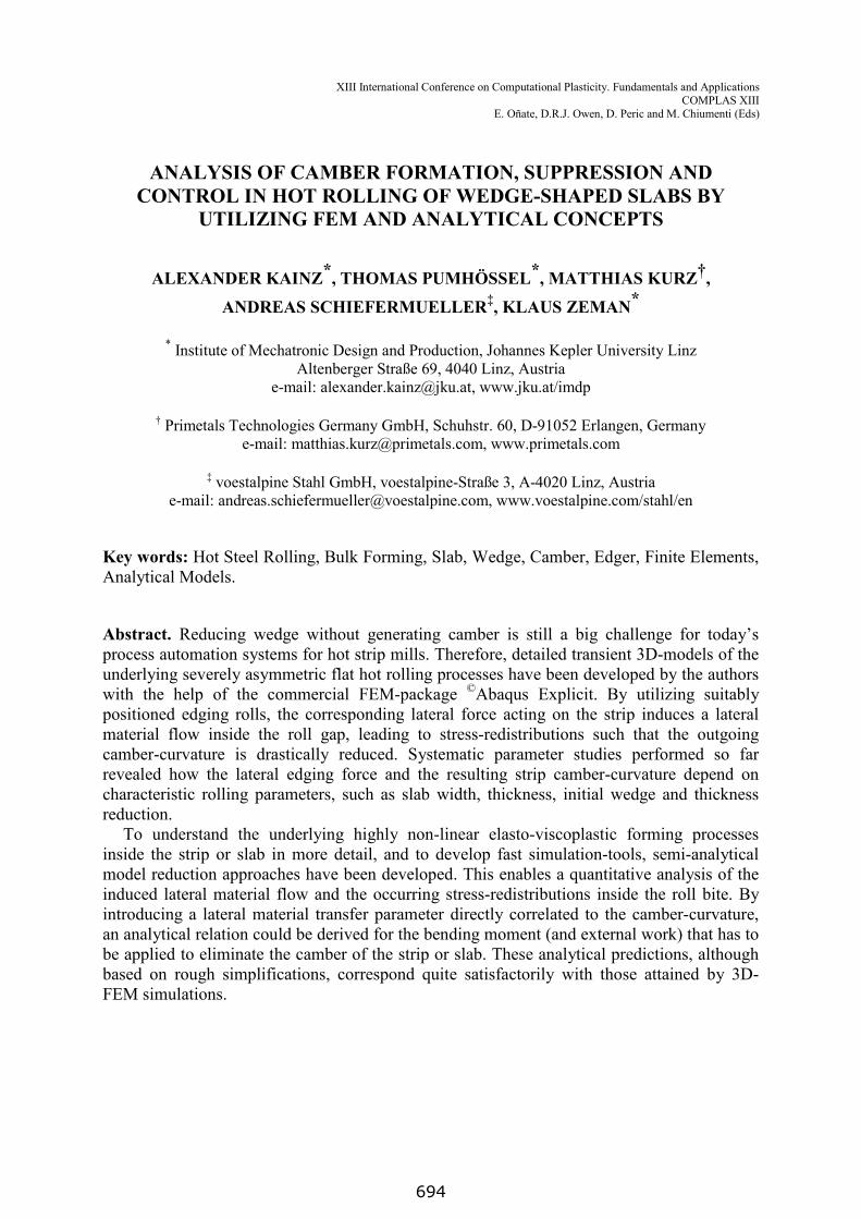
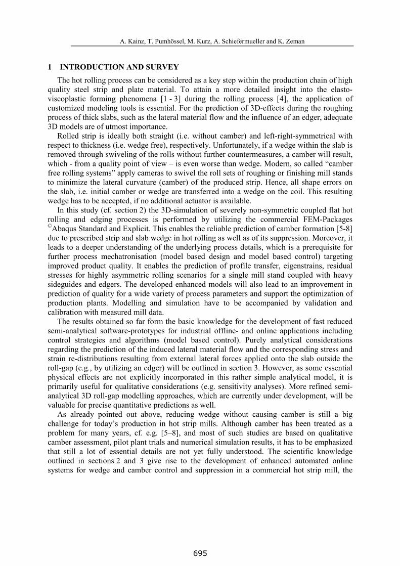
2 NUMERICAL INVESTIGATIONS Figure 1 shows a sketch of the investigated mechanical system. A strip with initial wedge
is rolled such that the wedge is eliminated entirely. Lateral movement of the strip on the entry side is prevented using side-guides. The elimination of the wedge is associated with a lateral material flow in the roll-bite, causing a strip with significant camber. To suppress the formation of this strip camber, a force controlled edger is proposed, see Figure 1. Initially, the upper work roll is positioned with some clearance above the resting strip. In the following step, the required rotational speed is applied to the work roll, and the work roll is lowered to the final strip thickness. The lowering of the work roll causes a transient stress distribution near the front crop of the strip, see exemplarily in Figure 2. The edger is brought to contact with the strip by applying a small lateral force ( )r
zEF to the edger when the front crop has passed the centerline of the edger. It is worth to note that the edger is connected to the inertial frame by a soft spring. Thereafter, ( )r
zEF is increased sinusoidally to the final constant value( )
,maxr
zEF . The effect of the lateral edger force ( ),max
rzEF on the formation of strip camber is
investigated in the following using the software package ©Abaqus Explicit, where special emphasis is placed on the influence of a variation of the system parameters initial width, thickness, wedge of strip, and thickness reduction.
Figure 1: Sketch of Abaqus model for investigating the influence of a force-controlled edger to the camber of rolled strips with initial wedge.
Figure 2: Exemplary Abaqus result of a rolled strip with initial wedge, depicting the formation of a quasi-stationary state for a constant lateral edger force.
Roll stand and strip are assumed to be symmetric with respect to the horizontal plane (x-z plane), and hence, numerical simulations are limited to the upper half. Work roll, side-guides and edger were modeled as rigid bodies, whereas an elasto-viscoplastically material law was assumed for the strip. To reduce the numerical simulation time, the edger was located closer to the work roll in the reduced model, i.e. at a distance ( ) / 3=r
we wel l , where the superscript ( )r
denotes the reduced quantity, and moreover, the mass scaling in Abaqus Explicit was set to
696
A. Kainz, T. Pumhössel, M. Kurz, A. Schiefermüller and K. Zeman
10. Comparative investigations with ©Abaqus Standard showed only marginal differences.Meshing was done using 50 elements across the width, and 8 elements across the half
thickness of the strip, with a continuous refining of the elements’ size from the core to the surface of the strip. Table 1 shows the default set of system parameters used for the numerical investigations.
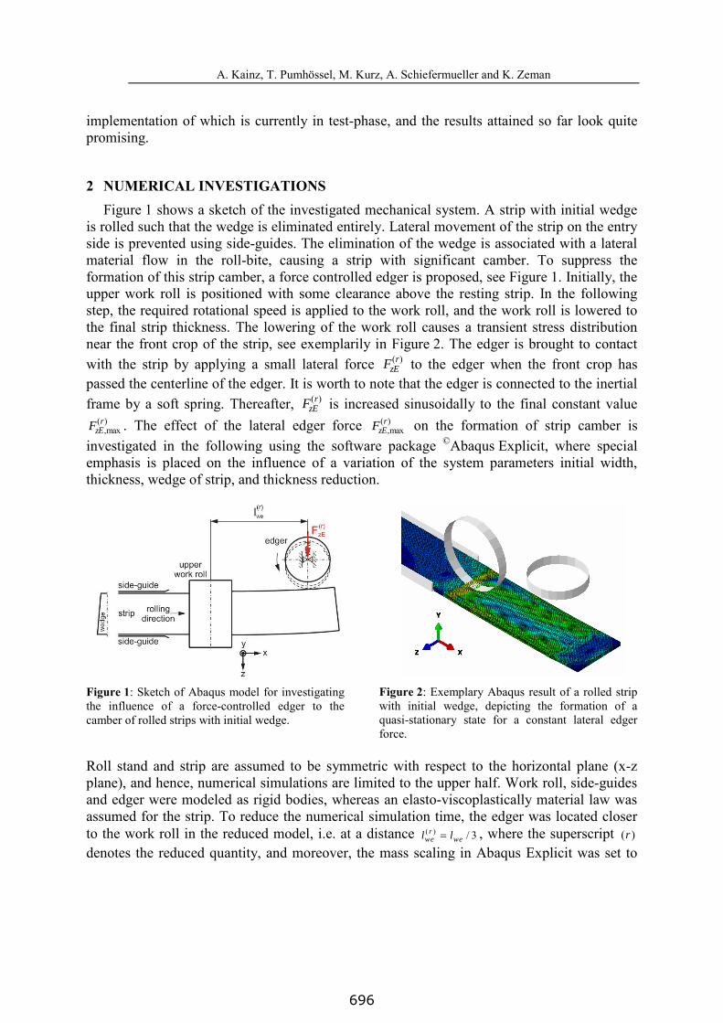
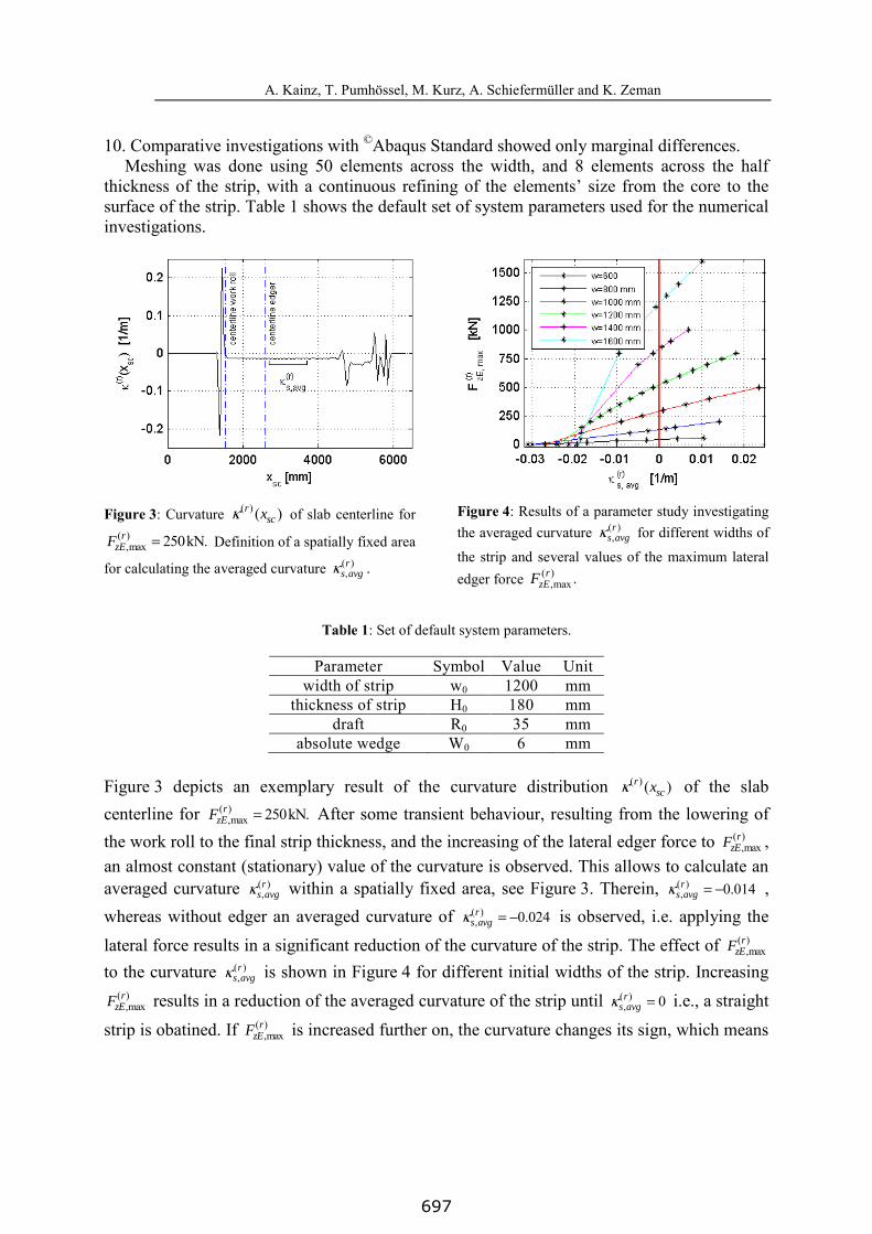
Figure 3: Curvature ( ) ( )rscxκ of slab centerline for
( ),max 250kN.=r
zEF Definition of a spatially fixed area
for calculating the averaged curvature ( ),r
s avgκ .
Figure 4: Results of a parameter study investigating the averaged curvature ( )
,r
s avgκ for different widths of
the strip and several values of the maximum lateral edger force ( )
,max .rzEF
Table 1: Set of default system parameters.
Parameter Symbol Value Unit width of strip w0 1200 mm
thickness of strip H0 180 mm draft R0 35 mm
absolute wedge W0 6 mm
Figure 3 depicts an exemplary result of the curvature distribution ( ) ( )rscxκ of the slab
centerline for ( ),max 250kN.=r
zEF After some transient behaviour, resulting from the lowering of the work roll to the final strip thickness, and the increasing of the lateral edger force to ( )
,maxr
zEF , an almost constant (stationary) value of the curvature is observed. This allows to calculate an averaged curvature ( )
,r
s avgκ within a spatially fixed area, see Figure 3. Therein, ( ), 0.014= −r
s avgκ , whereas without edger an averaged curvature of ( )
, 0.024= −rs avgκ is observed, i.e. applying the
lateral force results in a significant reduction of the curvature of the strip. The effect of ( ),max
rzEF
to the curvature ( ),r
s avgκ is shown in Figure 4 for different initial widths of the strip. Increasing ( )
,maxr
zEF results in a reduction of the averaged curvature of the strip until ( ), 0=r
s avgκ i.e., a straight
strip is obatined. If ( ),max
rzEF is increased further on, the curvature changes its sign, which means
697

A. Kainz, T. Pumhössel, M. Kurz, A. Schiefermüller and K. Zeman
that the strip bends to the opposite direction. This clearly demonstrates that a certain value of the lateral edger force exists which allows to fully suppress the formation of strip camber.
Figure 5: Relative maximum lateral edger force
,max ,max,0/zE zEF F corresponding to a strip with zero curvature for different values of the relative width
0/w w of the strip.
Figure 6: Resulting curvature of the full model when applying a lateral edger force
( ),max ,( 0)r
zE s avgF κ = , for which the curvature
vanishes in the reduced model.
Figure 5 depicts the relative edger force ,max ,max,0/zE zEF F necessary to suppress the strip’s curvature for variations of the relative width 0/w w of the strip. Therein, ,max,0zEF represents the required lateral edger force for the default set of system parameters according to Table 1. As expected, increasing the width of the strip results in a higher lateral edger force, necessary to suppress the formation of strip camber. This relationship can be desribed precisely by a polynomial of third order, see Figure 5.
The results presented up to now, are all related to the reduced model, where the edger is located closer to the work roll to save computational time. To check, if the results of the reduced model are valid also for the full model, where the edger is in its original position, a numerical evaluation of the full model based on the default set of system parameters, see Table 1, and the lateral edger force ( )
,max ,max /3= rzE zEF F was carried out. Figure 6 depicts the
corresponding curvature of the slab centerline of the full model. It can be clearly seen, that in the front area of the strip, which is rolled without contact between edger and strip, a well defined steady state can be observed, with a curvature 0.024≈ −κ . Applying the lateral edger force causes a short transient behaviour of the curvature, and immediately thereafter, a quasi steady state with 0.0≈κ is achieved. This demonstrates exemplarily, that the proposed reduced model is capable of predicting the behaviour of the full model.
The basis for suppressing the formation of strip camber when eliminating strip wedge, is the induction of a lateral material flow in the roll bite by applying a lateral force to the strip on the exit side. This concept benefits from the fact that the strip is already plastfied in the roll bite due to the thickness reduction achieved by the work rolls. In the present case, the ratio of the moment of the lateral edger force ,maxzEF compared to the moment plM that would benecessary for plastification of the strip in the roll bite in the absence of the rolling force reads
698

A. Kainz, T. Pumhössel, M. Kurz, A. Schiefermueller and K. Zeman
,max
( ) 2/ /( / 4) 0.065,∆ = =xx zE
Outpl we f cM M F l k H wσ i.e. only 6.5% of plM is necessary to modulate the
lateral material flow in the roll-bite such that a strip with approximately zero curvature is achieved.
Figure 7: Averaged axial stress ,xx avgσ at roll bite
exit in the quasi-stationary state with and without lateral edger force.
Figure 8: Difference of averaged axial stress ,xx avgσat roll bite exit with and without lateral edger force.
The effect of the lateral edger force on the distribution of the averaged axial stress over strip width is shown in Figure 7 for the default set of system parameters. Therein, axial stresses at the roll bite exit, averaged across the thickness of the strip, are displayed for the cases with, respectively without a lateral edger force being applied. The results hold for a well pronounced steady state. It can be seen clearly, that without edger, i.e. free formation of camber takes place, an axial stress distribution which is almost symmetric with respect to the center of strip occurs. In comparison, applying a constant lateral force causes an increase of stresses for lateral strip coordinates within [0, 600], and decreased stresses within [-600, 0].
The corresponding difference ,∆ xx avgσ between the axial stresses developing with and without lateral edger force, is given in Figure 8, indicating tensile stresses in the half of the strip adjacent to the edger, and compressive stresses in the opposite half. Within a range of about [-200, 200], ,∆ xx avgσ can be approximated by a linear relationship with sufficient accuracy.
Figure 9 shows the lateral material transfer factor ζ (defined in section 3, see Equations (5)) as a function of the relative edger force ,max ,max,0/zE zEF F and for different relative widths of the strip. If 1=ζ , total suppression of strip camber is achieved, whereas 0=ζ indicates free formation of camber. A material transfer factor 1>ζ corresponds to a scenario for which the lateral material flow, and therewith, the curvature of the strip changes its sign, i.e. the strip is bent to the opposite direction. So far, only a variation of the width of the strip was investigated. In the following, some results concerning the variation of strip thickness, wedge, and reduction are presented.
699

A. Kainz, T. Pumhössel, M. Kurz, A. Schiefermueller and K. Zeman
Figure 9: Lateral material transfer factor ζ for strips with different initial width and for different values of the lateral edger force ,max .zEF
Figure 10: Required relative edger force
,max ,max,0/zE zEF F to achieve a strip with zero curvature for variations of relative system parameters 0/p p .
Figure 10 shows a collection of the corresponding results. Increasing the thickness of the strip initially causes a larger required edger force to achieve a strip with zero curvature, see Figure 10. For 0/ 1.2> ≈H H , the relative edger force ,max ,max,0/zE zEF F , decreases slightly as the effect of the decreasing relative wedge on the required lateral force necessary to suppress strip camber formation overcompensates the effect of increasing strip thickness. The influence of the reduction meets the expectations - with increasing reduction, the required lateral edger force becomes smaller. With increasing wedge, a larger lateral force is required to suppress strip camber.
3 ANALYTICAL INVESTIGATIONS In this section, the behavior of a wedged slab running through one horizontal roll pass with
aligned rolls is investigated by analytical means. Due to the wedge on the entry side and the alignment of the rolls, the material undergoes different reductions on the operator side and on the drive side of the material. As a consequence, the side with higher reduction shows higher elongation. This results in a curvature of the material on the exit side and camber develops. The impact of an externally applied lateral force, e.g. resulting from an edger, would cause an asymmetric tension regime, which compensates for the different elongations by inducing an additional lateral material flow. Therefore, the wedge can (at least in principle) be eliminated fully without formation of camber by choosing the correct lateral force-value.
By utilizing analytical methods, the induced lateral material flow inside the roll-bite can be analyzed to some extent as follows. The x-coordinate of the underlying global Cartesian coordinate system denotes the rolling direction, whereas y and z indicate the thickness and lateral directions of the strip or slab, respectively (cf. Figures 1 and 2). A non-dimensional lateral coordinate is introduced via
700
A. Kainz, T. Pumhössel, M. Kurz, A. Schiefermueller and K. Zeman
[ ]1, 12w
z η η= → ∈ − + . (1)
Within the frame of perturbation theory, the special case of plane strain (i.e. no lateral material flow) can be considered as “undisturbed” scenario of pure thickness reduction with logarithmic strain values
( )( )
(0) (0)( )ln 0
Inc
xx yy Outc
H
Hε ε
= − = >
. (2)
For simplicity, linear wedge-profiles are assumed here for the strip entry- and exit profiles (In: before roll-gap entry, Out: after roll-gap exit) according to
( ) ( )( )
( )( ) 1
2
InInIn abs
C InC
WH H
Hη η
≅ −
( ) ( )
( )
( )( ) 1
2
OutOutOut abs
C OutC
WH H
Hη η
≅ −
(3)
Calculations taking into account more general strip-profiles were accomplished as well and will be outlined at the end of this section (cf. Equations (14) ff.).
By taking into account a small relative strip wedge change, defined as the difference of the absolute strip wedge values, divided by the respective nominal (C: Centerline) thickness values,
( )
( )
( )
( ) 1Out In
abs absrel relOut In
C C
W WW with W
H H
∆ ≡ − ∆ <<
(4)
the corresponding induced logarithmic (i.e., “true”) plastic strains inside the strip or slab at the roll gap exit can approximately be assumed to be of the form (in lowest order of ∆Wrel)
( ) [ ](0) (1 ) 2xx xx relWε η ε ζ η≅ + − ∆ (5a)
( ) [ ](0) 2yy yy relWε η ε η≅ − ∆ (5b)
( ) [ ]2zz relWε η ζ η≅ ∆ , (5c)
where the scalar “lateral material transfer factor” ζ is a measure of the magnitude of the lateral material flow involved. A value of zero indicates the case of plane strain and zero lateral flow, whereas a value of 1ζ = represents 100% lateral flow such that no longitudinal strain inhomogenities are induced across the strip’s width.
Note that shear strains are neglected here. The plastic incompressibility constraint is fulfilled exactly for the logarithmic strain tensor components (Equations (5a)-(5c))
( ) ( ) ( )1 1
0xx yy zzηε η ε η ε η
− <= <= ∀ + + = . (6)
By neglecting higher order terms in the relative strip wedge change ∆Wrel, the uniaxial equivalent plastic strain can be determined according to
701

A. Kainz, T. Pumhössel, M. Kurz, A. Schiefermueller and K. Zeman
( ) ( )( ) 2 2 2 (0)(0)
2 2 11 13 2 23
p relxx yy zz xx
xx
W ζε η ε ε ε ε ηε
∆ = + + ≅ + − . (7)
Within the frame of Levy-Mises [1 - 4] the deviatoric (i.e. trace-free) stress-components ijσ ′ of the Cauchy stress tensor are fully determined by the associated plastic flow rule. To
calculate the stresses itself, two more conditions have to be taken into consideration. The lateral force-equilibrium reduces here to
0zz zzp
z
σ ση η
′∂ ∂ ∂= → =∂ ∂ ∂
(8)
i.e., the lateral change of the hydrostatic pressure p is already prescribed via the determinationof ijσ ′ . The longitudinal stress boundary condition is given by
( ) (0)xx F F xxσ η σ σ σ= → = (9)
for prescribed mean front tension stress. These two conditions enable the unique determination of the hydrostatic pressure p and of the Cauchy stresses, which read in lowest order of ∆Wrel
( ) (0)123
f relF
xx
k Wp
ζη σ ηε
∆= − + +
( ) (0)
343
f relxx F
xx
k Wζσ η σ ηε
∆ = − (10a)
( ) (0)
2 343 3
f f relyy F
xx
k k Wζσ η σ ηε
∆ = − − ( )
3f
zz F
kσ η σ = −
, (10b)
where fk denotes the yield-strength value. When dealing with camber formation, the “material transfer factor” ζ as introduced in
Equations (5a) and (5b), is directly correlated to the camber-curvature κ
(1 )relW
wκ ζ−∆= − (11)
as can be shown easily via elementary geometric considerations. It takes its maximum value for the first limiting scenario, i.e., for zero lateral flow max0 relW wζ κ κ= → = = −∆ . For the opposite limiting scenario, i.e., for 1ζ = , the lateral flow inside the roll-gap suffices to fully eliminate the camber (i.e. 0κ = ). In that case longitudinal compressive stresses (σxx < 0) and tensile stresses (σxx > 0) are induced depending on the lateral position η , as follows quantitatively from Equation (10a). Moreover, the local roll separating force proportional to ~[-σyy] (cf. Equation (10b)) decreases in regions, where longitudinal tensile stresses occur, and increases in regions with compressive longitudinal stresses.
The external bending moment MB corresponding to the longitudinal stress distribution σxx(η) in Equation (10a) is determined by evaluating the integral
702

A. Kainz, T. Pumhössel, M. Kurz, A. Schiefermueller and K. Zeman
( ) ( )( ) 2/2
( )(0)
/2 4 2 3plast
Outwc fOut rel
B xxxxw
M
H w k WM z H z z dz
ζσε
+
−
∆= ≅
∫
. (12)
The corresponding plastic deformation work (per strip unit length) reads
( )max
2( )0( )
(0)16 3
Outc f relpl
B
xx
H w k WW M d
κ
κε∆
= =∫ . (13)
It should be emphasized that the bending moment required to eliminate camber (c.f. Equation (12)) is tiny (about 2-8%) compared to the value Mplast, which is necessary for “classical” strip bending, i.e., pure bending without thickness reduction by rolling. The underlying main reason is that due to strip thickness reduction inside the roll gap, plastification already occurs. Therefore, the material flow merely has to be “modulated”, i.e. only the stress-redistributions coupled to the additional lateral material flow have to be induced by applying this external bending moment.
A generalization of Equations (3) ff. from linear wedges to arbitrary non-linear strip-entry profiles is straight forward and can be performed systematically, e.g., by utilizing an expansion in series of Legendre-polynomials ( )kP η [9]. By performing a stress and strain analysis, based on a generalization of Equation (3) according to
( ) ( ){ }( ) ( ) ( )In In InCH H Hη η= + ∆ ( ) ( ){ }( ) ( ) ( )Out Out Out
CH H Hη η= + ∆ , (14)
and by defining a suitable auxiliary function ( )ηΨ
( ) ( ) ( ) ( )( ) ( )
( ) ( )0
In Out
j jIn OutjC C
H HP
H H
η ηη η∞
=
∆ ∆Ψ ≡ − ≅ Ψ
∑ , (15)
which can be expanded in terms of the complete orthogonal Legendre polynomials [9], one is directly led to the product representation
( ) ( ) ( ) ( )0
k kk
Pη η ζ η η∞
=
Ξ ≡ Ψ = Ξ∑ ( ) ( ) ( )1
1
2 12k k
kP dη η η
+
−
+→ Ξ = Ξ∫ . (16)
It should be emphasized that the scalar “lateral material transfer function” ( )ζ η involved in(16) is a generalization of the material transfer factor ζ introduced in Equation (5) representing a quantitative measure of the magnitude of the lateral material flow related to a relative strip profile change according to the function ( )ηΨ . The consistent determination ofthis quantity requires a full 3D roll-gap model and can be calculated either by enhanced 3D semi-analytical models (an enhanced variant is currently under development), or by analyzing 3D Finite Element simulation results. In general cases, the lateral material flow is inhomogeneous and varies in lateral direction. Therefore, it also has to be expanded in terms of Legendre-polynomials
703
A. Kainz, T. Pumhössel, M. Kurz, A. Schiefermueller and K. Zeman
( ) ( ) ( ) ( ) ( )1
0 1
2 12k k k k
k
kP P dζ η ζ η ζ η η η
+∞
= −
+= → = Ξ∑ ∫ . (17)
Combining the Equations (15) - (17) one is immediately led to the correlation between the Legendre coefficients involved
( ) ( ) ( ) ( ) ( ) ( )0 0 0
k k i j i jk i j
P P Pη η η ζ η ζ η η∞ ∞ ∞
= = =
Ξ = Ξ = Ψ = Ψ∑ ∑∑ (18a)
( )0 0
2 12k i j ijk
i j
kIζ
∞ ∞
= =
+Ξ = Ψ∑∑ with ( ) ( ) ( )
1
1ijk i j kI P P P dη η η η
+
−
= ∫ . (18b)
Note that for the analytical evaluation of overlap matrix elements ijkI a lot of literature exists. However, a numerical evaluation of the first (about) thousand values suffices in most cases considered (eventually in combination with asymptotic expansions and remainder term estimates). For the strains and stresses at roll gap exit the general representation in terms of the auxiliary functions ( )ηΨ and ( )ηΞ introduced above can be found
( ) ( ) ( ){ }(0) 1xx xxε η ε ζ η η= + − Ψ ( ) ( ) 0(0)
323
fxx F
xx
kσ η σ η
ε
= − Ξ − Ξ
(19a)
( ) ( ){ }(0)yy xxε η ε η= − − Ψ ( ) ( ) ( )*
0(0)
323
fyy F f
xx
kkσ η σ η
ε
= − − Ξ − Ξ
(19b)
( ) ( ) ( )zzε η ζ η η= Ψ 0(0)
3123
fzz F
xx
kσ σ
ε
= − − Ξ
. (19c)
For the bending moment analogous to Equation (12) one obtains the integral representation
( ){ }( )
( )
( ) 2 1
0(0)1
3 14 2
Out
Outc
Outc f
Bxx
H
H
H w kM dη η η
ε
+
−
∆ ≅ + Ξ − Ξ ∫ . (20)
These general expressions represent analytical solutions for arbitrary non-linear changes of strip thickness profiles according to Equation (14) and (15). The special case of a linear wedge (cf. above) can be recovered easily by taking into consideration the setting
( ) 0ζ η ζ= , ( ) ( )12 relwη ηΨ = ∆ ( ) ( ) ( )0 0 1
12 relW Pη ζ η→ Ξ − Ξ = ∆ , 0 0ζΞ = Ψ = . (21)
with the relative strip wedge change relW∆ being defined in Equation (4). For the practically
especially important case of second order (parabolic) strip shapes, one immediately obtains
( ) ( ) 2relCη ηΨ = ∆ ( ) ( ) ( )0 0 2
23 relC Pη ζ η→ Ξ − Ξ = ∆ and ( )0 0
13 relCζ ζΞ = Ψ = ∆ , , (22)
where the relative strip crown change is denoted by relC∆ . To conclude this section it should be emphasized that the fully analytical considerations
presented so far lead to results, which describe the underlying technical-physical rolling
704

A. Kainz, T. Pumhössel, M. Kurz, A. Schiefermueller and K. Zeman
scenario qualitatively correctly to some extent and can be used (e.g.) for sensitivity analyses. However, as essential physical effects, such as bulk shear stresses and lateral Coulomb friction, are not explicitly incorporated in the analytical model presented here, severe quantitative deviations may occur for some quantities. This drawback will be overcome by more refined semi-analytical 3D roll-gap modelling approaches currently under development.
4 CONCLUSIONS In the present study, a new approach has been presented to minimize both camber and
wedge, respectively, with negligible need for mechanical modifications. The behavior of a wedged slab, running through one horizontal roll pass with aligned rolls, and being exposed to additional lateral forces outside the roll-gap, resulting e.g. from an edger, was investigated in detail. It could be proven by both numerical 3D-FEM and by analytical methods that the principle of inducing an additional lateral flow inside the roll gap by utilizing external lateral forces or bending moments is highly efficient. As plastification already occurs inside the roll gap, these additional loads are comparably low, as they merely have to induce a re-distribution of the already existing plastic material flow. First results from a commercial production hot rolling mill, where a camber control system and an associated wedge control system based on these concepts was realized, look quite promising.
ACKNOWLEDGEMENT This work has been supported by the Austrian COMET-K2 programme of the Linz Center
of Mechatronics (LCM), and has been funded by the Austrian federal government, the federal state of Upper Austria, voestalpine Stahl and by Primetals Technologies (formerly S-VAI).
REFERENCES [1] Simo, J.C. and Hughes, T.J.R. Computational Inelasticity. Springer, New York, (1998). [2] Neto, E.S, Peric, D. and Owen, D.R.J. Computational Methods for Plasticity (Theory and
Applications). John Wiley & Sons Ltd., Chichester, United Kingdom, (2008). [3] Belytschko, T, Liu, W.K. and Moran, B. Nonlinear Finite Elements for Continua and
Structures. John Wiley & Sons, Chichester, New York, (2002). [4] Hosford, W.F., Cadell, R.M. Metal Forming (Mechanics and Metallurgy). Cambridge
University Press, Cambridge, New York, (2007). [5] Montague, R.J., Watton, J. and Brown, K.J. A machine vision measurement of slab
camber in hot strip rolling. J. of Materials Processing Technology (2005) 168:172–180. [6] Shiraishi, T., Ibata, H., Mizuta, A., Nomura, S., Yoneda, E. and Hirata, K. Relation
between camber and wedge in flat rolling under restrictions of lateral movement. ISIJ Int.(1991) 31 (No. 6):583–587.
[7] Knight, C.W., Hardy, S.J., Lees, A.W. and Brown, K.J. Investigations into the influence of asymmetric factors and rolling parameters on strip curvature during hot rolling. J. of Materials Processing Technology (2003) 134:180–189.
[8] Nilsson, A. FE simulations of camber in hot strip rolling. J. of Materials Processing Technology (1998) 80-81:325-329.
[9] Gradshteyn, I.S. and Ryzhik, I.M. Table of Integrals, Series and Products. Academic Press, San Diego (1980).
705