analysis of a low-angle annular expander nozzle
TRANSCRIPT
Hindawi Publishing Corporation Shock and Vibration Volume 2015 Article ID 675861 8 pages httpdxdoiorg1011552015675861
Research Article Analysis of a Low-Angle Annular Expander Nozzle
Kyll Schomberg1 John Olsen1 and Graham Doig12
1 School of Mechanical and Manufacturing Engineering UNSW Sydney NSW 2052 Australia2Aerospace Engineering Department California Polytechnic State University San Luis Obispo CA 93407 USA
Correspondence should be addressed to Kyll Schomberg kyllschombergunsweduau
Received 16 October 2014 Accepted 10 March 2015
Academic Editor Chao Tao
Copyright copy 2015 Kyll Schomberg et al This is an open access article distributed under the Creative Commons Attribution License which permits unrestricted use distribution and reproduction in any medium provided the original work is properly cited
An experimental and numerical analysis of a low-angle annular expander nozzle is presented to observe the variance in shock structure within the flow field A RANS-based axisymmetric numerical model was used to evaluate flow characteristics and the model validated using experimental pressure readings and schlieren images Results were compared with an equivalent converging-diverging nozzle to determine the capability of the wake region in varying the effective area of a low-angle design Comparison of schlieren images confirmed that shock closure occurred in the expander nozzle prohibiting the wake region from affecting the area ratio The findings show that a low angle of deflection is inherently unable to influence the effective area of an annular supersonic nozzle design
1 Introduction
The substantial cost of transporting payload into orbit has created the demand for a reusable single stage launch system It has been estimated that a reusable single stage launch system has the potential to reduce the cost per kilogram to orbit by an order of magnitude [1] Propulsion systems fitted with conventional convergent-divergent nozzles which operate from sea level to the vacuum conditions (Space Shuttle Main Engine Vulcain etc) are currently subject to efficiency losses of up to 15 [2] The fixed area ratio design employed in these nozzles produces efficiency losses by forcing the pressure of the exhaust at the nozzle exit plane to remain constant Optimal nozzle efficiency is achieved when the pressure of the exhaust exiting the nozzle is equal to that of the receiver As the receiver or local atmospheric pressure is a function of altitude optimal efficiency is restricted to a single altitude for a fixed nozzle with pressure losses incurred at all other altitudes To increase the feasibility of single stage launch systems techniques to compensate for the variation in atmospheric conditions are required Nozzle concepts that compensate for this variation have existed in literature for over 50 years [3] and are generally classed with respect to the adaptive mechanism employed that is controlled flow separation devices [4 5] and passive area variation nozzles [6 7]
In a supersonic nozzle flow separation occurs due to stagnation of the boundary layer as a result of a strong adverse pressure gradient at the nozzle wall [8] Controlled flow separation devices attempt to vary the nozzle area ratio by intentionally inducing this phenomenon to reduce the effective exit area [4] The static wall pressure at which the flow separates can be predicted with reasonable accuracy [9 10] However the process from ldquofull-flowingrdquo to separated flow conditions is not fully understood [11] and can induce high vibrational and thermal loads to the nozzle wall [12] Additionally this method of altitude compensation is inhershyently a ldquostagedrdquo process only capable of reducing pressure losses through restricting the operating altitude range of each discrete stage [13] Passive variable area nozzle concepts adapt for changing atmospheric pressure through a continual adjustment of the effective nozzle exit area and therefore a continual adjustment of the exhaust pressure at the nozzle exit plane Variation of the effective area occurs through either an external (plug nozzle) [6] or an internal (expansionshydeflection nozzle) [7] interaction between the supersonic exhaust with the receiver
The variation of effective nozzle area is achieved by the manipulation of local atmospheric conditions In the expansion-deflection nozzle this process is facilitated through the use of a central flow deflector commonly referred to as a pintle The deflection of the supersonic exhaust radially
2 Shock and Vibration
Compression waves
Pintle
Moving shear layer increases effective area ratio with increasing
altitude Variable shear layer
Supersonic exhaust
Viscous recirculating wake region ldquoopenrdquo to
atmosphere at low altitude
Inclined nozzle throat
Nozzle contour
Figure 1 Half diametric cross section of the expansion-deflection nozzle behavior in open mode
outwards towards the nozzle wall results in the creation of a wake region at the base of the pintleThe interaction between the subsonic recirculating wake and supersonic exhaust produces a shear layer which acts to vary the effective area ratio of the nozzle and limit expansion of the exhaust flow The location of the shear layer and effective area ratio are determined by the pressure of the wake area In altitude compensating or ldquoopen wakerdquo mode the pressure of the wake region is theoretically equal to the local atmospheric pressure [7] Therefore during open wake operation the location of the shear layer will ideally ensure optimal expansion of the exhaust respective to ambient conditions The wake area is largest at high receiver pressure and reduces as receiver pressure decreases This increases the effective nozzle area ratio until the physically defined maximum is reached Operation at the physically defined area represents the design point of the nozzle and further reduction in receiver pressure results in an operational transition to nonaltitude compensating or ldquoclosed wakerdquo mode Nozzle behavior during closed mode operation is equivalent to a fixed area converging-diverging (CD) nozzle and can be modeled using conventional supersonic flow theory Variations in expansion-deflection nozzle behavior during ldquoopenrdquo and ldquoclosedrdquo operating modes are shown in Figures 1 and 2
The plug and truncated plug (aerospike) nozzle have arguably received the most attention out of all altitude-adaptive nozzle concepts irrespective of the large base drag increased heat flux and variation in thrust levels at transonic velocities [14] The preference of the plug nozzle over the expansion-deflection nozzle appears to have stemmed from a report on an early investigation into variable area nozzles [15] This report concluded that the altitude adaptive potential of the expansion-deflection nozzle was low roughly equivalent to a conventional converging-diverging (CD) nozzle Howshyever it should be noted that the expansion-deflection nozzle utilized in [15] appeared to follow design principals consistent with Mueller et al [16] as opposed to Rao the developer of the expansion-deflection concept [7] This is significant because Muellerrsquos work involved instigating an early transition from
Shocks from intersectingshear layer
Pintle
Moving shear layer increases area to
physically defined maximum
Variable shear layer between exhaust and wake
Supersonic exhaust
Wake ldquoclosedrdquo to atmosphere athigh altitude
Inclined nozzle throat
Nozzle contour
Figure 2 Half diametric cross section of the expansion-deflection nozzle behavior in closed mode
Rao [7]
Mueller et al [16]
Wasko [15] 120579
∙ 90∘ throat
∙ Rounded pintle
∙ Open wake
∙ 20ndash45∘ throat ∙ Sharp pintle
∙ Closed wake
∙ Axially inclined throat
∙ Low throat angle
∙ Sharp 15∘ pintle
Figure 3 Expansion-deflection nozzle design comparison
open to closed wake mode therefore producing a design inherently unable to compensate for altitude A comparison of expansion-deflection nozzle designs is shown in Figure 3
In the present work a low-angle annular expander nozzle has been designed using similar principals to a Wasko expansion-deflection nozzle Evidence of wake closure during ldquoopen moderdquo operation would confirm that results obtained in [15] were a function of the design used as opposed to an inherent flaw within the expansion-deflection nozzle concept In this work the operating pressure ratio was kept within the overexpanded regime to maintain nozzle operation in ldquoopen wakerdquo or altitude compensating mode To generate numerical results computational fluid dynamics (CFD) methods were selected over the traditional method of characteristics due to the capability of CFD in describing all flow regions within the nozzle The method of characteristics is limited to inviscid supersonic flow fields and breaks down in the subsonic viscous wake Accurate modeling of wake behavior is therefore imperative due to the considerable effect
3 Shock and Vibration
this region has on the overall nozzle flow and therefore the capability of the wake region in influencing effect nozzle area
2 Design Methodology
All of the experimental work was conducted in the aerodyshynamics laboratory at UNSW Australia Dry air at a maximum stagnation pressure of 700 kPa was used as the test fluid The receiver pressure was fixed for all tests at the value of local atmospheric pressure A baseline pressure ratio of five was used to initiate the design process as the stagnation pressure could be varied above and below this value to observe nozzle behavior over a theoretical altitude range Nozzle operation was kept to overexpanded (OX) and grossly overexpanded flow conditions (GOX) In this work GOX flow was defined as nozzle operation at a pressure ratio lower than that required for flow separation This was achieved by applying Summerfieldrsquos criteria [9] to the baseline pressure ratio to yield a design pressure ratio The corresponding nozzle area ratio was determined from the design pressure ratio assuming isentropic flow conditions This assumption is commonly used for supersonic nozzles in the design phase [2] and was deemed to be satisfactory for this purpose as relative nozzle behavior was the performance measure in this work
The nozzle throat was sized with respect to the flow rate of the compressor and to ensure a sufficient area ratio to allow the assumption of stagnation conditions at the inlet The nozzle throat radius (119903 ) was determined through assuming
119905 isentropic flow continuity and sonic conditions at the throat and a value of 0015 m was used The difference between inlet flow parameters from stagnation values was estimated from the area ratio of 12 between the inlet and throat and found to be less than 02 This value was deemed sufficient to enable stagnation conditions to be assumed at the nozzle inlet and quarter circle of radius 267119903 was used to construct the
119905 convergent section A divergence contour at a constant angle of 10∘ and total area ratio of 234 was utilized for the expansion section of the nozzle
The fixed geometrical inlet required an unconventional rig design to achieve the required nozzle geometry A pintle attachment was placed upstream of the nozzle and fixed using a strut-based support structure Although the velocity at the inlet was relatively low (lt15 msminus1) and the attachment support structure aerodynamically shaped to reduce flow interference it was decided to use an annular CD nozzle to negate any bias caused by the attachment A pintle diameter of 08119903 was used to satisfy a factor of safety of 10 for this
119905 connection Following the throat area the cross sectional area of the CD pintle attachment was gradually reduced to a point Comparatively in the expander nozzle the pintle diameter was increased downstream of the throat and encompassed a sharp trailing edge consistent with the design of Wasko [15] A ratio of pintle base to nozzle exit area of 10 was used for the expander configuration resulting in a postthroat length of 13119903 Figure 4 shows the conventional (CD) and expander
119905 (ED) nozzle configurations
All schlieren images were obtained using a vertical knife edge z-type setup A mercury lamp was used as the light
1 2 3 4 5 6 7
CD
ED x
L
30 mm
Figure 4 Half diametric sectioned view of the CD and ED nozzle configurations
source in conjunction with two 6010158401015840 astronomical grade focal mirrors and a 50 cut-off filter Images were captured by Photron FASTCAM high speed camera recording images at a resolution of 1024 times 1024 pixels at 3000 f ps Static pressure values were taken directly from analogue gauge readings after the nozzle flow had stabilized The 1 mm diameter tapping ports were spaced at 10 mm increments in the axial direction so as not to affect flow structure Tapping locations 3 and 5 were offset by 90∘ to increase the number of overall readings All tapping locations were duplicated at 180∘ to enable an average pressure value to be taken between both points The importance of the throat and exit pressure reading warranted a tapping on each 90∘ axis and an average was taken over the four total readings Sources of experimental error in the static pressure readings were quantified using the calibration error and incremental errors in the gauge readings and were found to be 4 To accommodate a tapping at the theoretical nozzle exit the divergent section was extended by approximately 5 mm Although this modification would introduce additional expansion of the flow field and affect the exit shock pattern it was deemed necessary to ensure an adequate pressure distribution throughout the divergent section
3 Numerical Model
All numerical results were generated through the comshymercially available ANSYS Fluent 145 software Fluid flow through both nozzle configurations was treated as compressshyible and turbulent The boundary conditions were consistent with the pressure values recorded during experiments and implemented using a pressure inlet and outlet for all numerishycal models A time or Reynolds averaged (RANS) approach to turbulence modelling was adopted due to the relatively steady nature of a full-flowing nozzle and the reduced computational expense required Initial turbulence parameters were derived from the Reynolds number and boundary layer thickness at the nozzle inlet and calculated using a turbulent intensity of 36 and length scale of 168 mm Due to the low stagnation enthalpy air wasmodelled as ideal gas and a three-coefficient Sutherland model was used for viscosity [17]
The axisymmetric pressure-based coupled solver was used in conjunction with second order spatial discretization
4 Shock and Vibration
15∘
763rt
153rt
763rt
Figure 5 Mesh structure and downstream exhaust flow domain
schemes for all calculations Surface monitors were set on the 08
nozzle inlet nozzle exit and outflow domains to record the mass flow rate in addition to the static pressure and velocity
06magnitude at the nozzle exit Convergence was deemed to have been achieved when the values at each surface monitor
1080604
Coarse Standard
Fine Exp
xL
changed by less than 01 over 500 iterations Additionally a variation of mass flux of less than 01 between the inlet and outlet was required to satisfy continuity through the domain The geometric domain was consistent between all models excluding the pintle The effects of the nose cone and attachment struts on the flow field were assessed in a preliminary analysis and found to be negligible This
PP
0
04
enabled the geometry to be simplified to an axisymmetric configuration to aid in the discretization process The outflow region was sized in order to ensure the effect of domain boundaries on the flow was negligible A fully structured spatial discretization scheme comprised of quadrilateral cells was used for all models Figure 5 details the mesh structure
02
0
and dimensions of the downstream exhaust region used in Figure 6 Effect of mesh refinement on the static pressure distribushytion
all models As all nozzle operation was exclusively within the overexpanded regime strong pressure gradients were expected to be present at the nozzle wall To ensure that flow behavior under these conditions could be modelled accurately the first cell height was controlled to maintain a nondimensional wall distance (119910+) of 1
31 Grid Convergence A comparison of experimental and numerical static pressure readings and schlieren images was used to determine independence of grid density Refinement of grid between levels was achieved by progressively splitting each cell in the numerical domain into four and resulted in a cell count of 09 36 and 144 times 105 for the coarse standard and fine mesh levels respectively Strategic refinement of the coarse and standard grids was used to determine if the accuracy of the predicted shock structure could be improved at a greatly reduced computational cost This was achieved by calculating the pressure gradient between cells and splitting all individual cells if the normalized pressure gradient was greater than 005 This process was completed twice after convergence had been achieved and approximately doubled the cell count in the coarse and standard grids denoted by coarse (refined) and standard (refined) respectively
The turbulence model used for all GCI calculations was the Spalart-Allmaras (SA) model a one-equation turbulence model developed specifically for aerodynamic flow fields
involving wall bounded flows [18] The SA model was conshysidered suitable for this purpose due its proven capability of accurately modeling complex flows involving shock waves [19ndash23] The CD GOX case was used for the GCI due to the known close correlation of a CD nozzle with analytical results [24] Errors in experimental pressure readings were quantified through consideration of gauge calibration error pressure increment spacing and the known manufacturing tolerance of plusmn015 mm The effect of grid density on pressure distribution and numerical schlieren is shown in Figures 6 and 7 respectively
Variation between numerical pressure distributions was minimal across all levels of refinement Inspection of the location of flow separation showed that the coarse distribushytion was predicted 1 earlier This discrepancy was annulled through refinement of the coarse mesh
The effect of mesh refinement on predicted shock strucshytures was significant Shock resolution in the coarse mesh was greatly increased throughout the refinement process This process was seen to fully develop the cap shock pattern in both the coarse and standard mesh levels The refined coarse mesh was used for all future simulations due to the greatly reduced computational time small numerical uncertainty
5 Shock and Vibration
20mm
Coarse
Coarse (refined)
Standard
Standard (refined)
ture
08
06
PP
0
08 1
04
02
0 04 06
xL
Inviscid k-120596 SST SA Exp k-120576
Figure 8 Effect of turbulence model on the pressure distribution
predicted in the shock structure and negligible difference in the pressure distribution
32 Turbulence Modelling To assess the influence ofmodeled turbulence in the flow field the SA model was compared to the 119896-120596 shear stress transport model [25] (119896-120596 SST) and the 119896-120576 realizable model [26] (119896-120576) both of which have been used in previous work to model similar flow fields [27] In addition to varying the turbulence model an inviscid solution was compared to assess the influence of turbulence itself within the flow field Figures 8 and 9 outline the effect of turbulence model variation on the pressure distribution and predicted shock structure
20mm
Experiment
Inviscid
Spallart-Allmaras (SA)
k-epsilon realizable (k-120576)
k-omega SST
Figure 7 Effect of mesh refinement on the predicted shock strucshy
(k-120596 SST) Fine
Figure 9 Effect of turbulence model on the predicted shock strucshyture
The selection of the turbulence closure model had a considerable effect on the predicted flow field structure The inviscid solution did not predict flow separation whereas the 119896-120596 SST solution prematurely predicted separation compared to the experimental values A large variation in numerical schlieren was evident between all models highlighting the salient effect of turbulence within the flow field A numerishycally generated secondary shock was present in all models This effect was considerable in the 119896-120596 SST solution and appeared to cause dissipation of the Mach disk Numerical diffusion in the 119896-120576 realizable resulted in low resolution of the flow structure particularly in the secondary shock diamond The SA turbulence model was therefore selected for use in all future calculations due to the close correlation with experimental pressure values increased shock structure detail and high computational efficiency
4 Results and Discussion
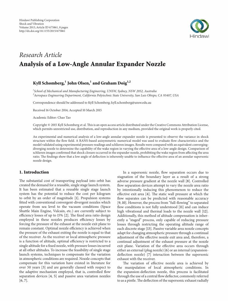
41 Grossly Overexpanded (GOX) Condition Under GOX flow conditions separation was expected to occur in the CD configuration Theoretically separation should be avoided under all conditions in a functional expander-type nozzle due to influence of the wake region However wake closure would produce flow characteristics equivalent to the CD nozzle The measured stagnation pressures were 490 and 442 atm in the CD and expander (ED) configurations respectively Figures 10ndash12 compare numerical and experimental pressure distributions and schlieren images
The numerical pressure distributions were within the experimental tolerances in both configurations Flow sepashyration occurred at 119909119871 = 0925 for both models inferring favorable flow conditions in the ED nozzle relative to the lower stagnation pressure Increased postthroat pressure values in the ED nozzle were caused by the formation of
6 Shock and Vibration
108
08
06
06
04
04
02
0
PP
0
xL
ED
ED
CD
CD CD exp ED exp
condition
Secondary (trailing) shock
Shock angles Outline due to 1D gradient calculation
Wake dominated flow
10 mm
37∘
39∘
Figure 12 Comparison of ED schlieren images in the GOX flow condition
Figure 10 Comparison of pressure distributions in the GOX flow
Artificially induced shock Mach disk fracture
Shock angles Outline due to 1D gradient calculation
10 mm
34∘
35∘
ED CD CD exp
ED exp
1080604
xL
08
06
04
02
0
PP
0
ED
CD
Figure 11 Comparison of CD schlieren images in the GOX flow condition
compression waves and a reduced rate of area ratio increase as a result of the pintle geometry The discrepancy between the shock diamond shadings was a result of the calculation of density gradient explicitly in the longitudinal direction Measured shock angles were within 2∘ for both configurashytions where a higher shock angle in the ED configuration was indicative of the lower stagnation pressure The distortion of a visible Mach disk evident in the ED configuration would be expected within a wake-embedded flow field However the intersection of shock diamonds with the flow axis downshystream showed that wake itself was ldquoclosedrdquo and that nozzle behavior was within the nonaltitude compensating regime The secondary or trailing shock wave was a result of the sharp pintle edge known to artificially induce wake closure [16]
42 Overexpanded (OX) Condition Theoretically flow sepashyration should be avoided when either nozzle operates under general OX conditions [9] However it is important to note that the inherent instability of flow separation makes accurate prediction difficult [11] and that the purely empirshyical Summerfieldrsquos criterion [9] is unable to account for
Figure 13 Comparison of pressure distributions in the OX condishytion
the amplification of boundary layer aggravation present in low Mach number flows [27] The measured stagnation pressures were 633 and 646 atm in the CD and ED configshyurations respectively Figures 13ndash15 compare numerical and experimental pressure distributions and schlieren images
A close correlation between numerical pressure distrishybutions and experimental values was again observed with the main discrepancy located within the throat region in both configurations Flow separation occurred within the ED model and was avoided in the CD model irrespective of the higher ED stagnation pressure The location of the primary shock was within 2∘ between models with a lower shock angle present in the nonseparating CD nozzle A fracture in the Mach disk was consistent with the GOX results in the CD configuration The existence of a Mach disk in the ED nozzle represented a shock-dominated flow field An artificially induced shock was again present in the CD nozzle whereas the trailing shock generated from postpintle expansion caused a secondary shock in the ED nozzle No evidence of a wake area was evident in the ED model
7 Shock and Vibration
Artificially induced shock Mach disk fracture
Shock angles Outline due to 1D gradient calculation
10 mm
31∘
325∘
Figure 14 Comparison of CD schlieren images in the OX flow conshydition
Shock dominated flow
Shock angles Outline due to 1D gradient calculation
Secondary (trailing) shock
33∘
35∘
10 mm
Figure 15 Comparison of ED schlieren images in the OX flow conshydition
confirming that operation of the configuration was in ldquoclosed moderdquo and that performance equivalent to a CD nozzle was expected
5 Conclusions
A low-angle expander nozzle has been experimentally and numerically compared to a CD nozzle at an OX and GOX pressure operating condition Verification and validation of the RANS-based numerical model indicated that the variation in static pressure distribution with respect to grid density was low Comparatively grid density had a direct effect on shock resolution A targeted approach to grid refinement using the normalized pressure gradient between cells represented the flow for minimal computational cost Selection of turbulence model had a considerable effect on the numerical solution affecting both the separation point of the flow and the shock structure within the nozzle flow field This was particularly evident in the description of the quasiopen wake flow field observed in the expander nozzle at GOX conditions
The experimental and numerical static pressure distribushytions were within experimental uncertainty values at both operating conditions in the CD and expander nozzles Preshymature wake closure was observed in the expander nozzle at
the GOX operating condition by comparing schlieren images confirming that the influence of the wake region of the effective area of the expander nozzle was low The consistent static pressure values at the nozzle exit and distribution throughout the divergence section suggested flow behavior in the expander nozzle configuration was largely independent of the level of overexpansion The results highlight the limitashytions of a low-angle flow deflector in generating a wake region that is capable of varying the effective area of a supersonic nozzle Use of a low-angle expander design should therefore be avoided for use in altitude-adaptive nozzle concepts such as the expansion-deflection nozzle
Conflict of Interests
The authors declare that there is no conflict of interests regarding the publication of this paper
Acknowledgments
The authors would like to acknowledge Mr Charles Queriaud for his assistance with the experimental schlieren imagery and Mr Terry Flynn for his assistance with setting up the experimental rig and obtaining experimental pressures The contributions of Mr Ian Cassapi Mr Andrew Higley and Mr Seetha Mahadeven in the manufacture of all experimental components are also acknowledged
References
[1] N V Taylor C M Hempsell J Macfarlane et al ldquoExperimental investigation of the evacuation effect in expansion deflection nozzlesrdquo Acta Astronautica vol 66 no 3-4 pp 550ndash562 2010
[2] G P Sutton and O Biblarz Rocket Propulsion Elements chapter 2 3 John Wiley amp Sons New York NY USA 7th edition 2001
[3] G V Rao ldquoRecent developments in rocket nozzle configurashytionsrdquo ARS Journal vol 31 no 11 pp 1488ndash1494 1961
[4] M Horn and S Fisher ldquoDual-bell altitude compensating nozzlesrdquo NASA CR-194719 National Aeronautics and Space Administration 1994
[5] G Hagemann D Manski and G Krulle ldquoDual expander engine flowfield simulationsrdquo in Proceedings of the 31st Joint Propulsion Conference and Exhibit AIAA 95-3135 AIAA San Diego Calif USA 1995
[6] G V R Rao ldquoSpike nozzle contour for optimum thrustrdquo Ballistic Missile and Space Technology vol 2 pp 92ndash101 1961
[7] G V R Rao ldquoAnalysis of a new concept rocket nozzlerdquo Journal of Liquid Rockets and Propellants vol 2 pp 669ndash682 1960
[8] E L Morrisette and T J Goldberg ldquoTurbulent flow separation for overexpanded nozzlesrdquo NASA Technical Paper 1207 1978
[9] M Summerfield C Foster and N Swan ldquoFlow separation in overexpanded supersonic exhaust nozzlesrdquo Journal of Propulshysion vol 24 no 9 pp 319ndash321 1954
[10] R H Schmucker ldquoStatus of flow separation prediction in liquid propellant rocket nozzlesrdquo NASA N75-120618 1974
[11] J Ostlund Supersonic flow separation with application to rocket engine nozzles [PhD thesis] Royal Institute of Technology Stockholm Sweden 2004
8 Shock and Vibration
[12] M Onofri and F Nasuti ldquoThe physical origins of side loads in rocket nozzlesrdquo in Proceedings of the 35th Joint Propulsion Conference and Exhibit AIAA Los Angeles Calif USA 1999
[13] G Hagemann M Frey and D Manski ldquoA critical assessment of dual-bell nozzlesrdquo in Proceedings of the 33rd Joint Propulsion Conference and Exhibit 3299 p 3297 Seattle Wash USA 1997
[14] G Hagemann H Immicht M Terhardt and G Dumnov ldquoCritical assessment of the linear plug nozzle conceptrdquo in Proceedings of the AIAA 37th Joint Propulsion Conference and Exhibit AIAA 2001-3683 Salt Lake City Utah USA July 2001
[15] R A Wasko ldquoPerformance of annular plug and expansion-deflection nozzles including external flow effects at transonic mach numbersrdquo NASA TN D-4462 1968
[16] T J Mueller W P Sule and C R Hall ldquoCharacteristics of separated flow regions within altitude compensating nozzles variationrdquo UNDAS TN-029-FR-9 University of Notre Dame 1971
[17] W Sutherland ldquoThe viscosity of gases and molecular forcerdquo Philosophical Magazine vol 36 pp 507ndash531 1893
[18] P Spalart and S Allmaras ldquoA one-equation turbulence model for aerodynamic flowsrdquo La Recherche Aerospatiale vol 1 no 5 pp 5ndash21 1992
[19] G C Doig T J Barber E Leonardi A J Neely and H Kleine ldquoMethods for investigating supersonic ground effect in a blowdown wind tunnelrdquo Shock Waves vol 18 no 2 pp 155ndash159 2008
[20] G Doig T J Barber E Leonardi A J Neely H Kleine and F Coton ldquoAerodynamics of a supersonic projectile in proximity to a solid surfacerdquo AIAA Journal vol 48 no 12 pp 2916ndash2930 2010
[21] G Doig ldquoTransonic and supersonic ground effect aerodynamshyicsrdquo Progress in Aerospace Sciences vol 69 pp 1ndash28 2014
[22] K Schomberg and J Olsen ldquoAltitude compensation in expanshysion deflection nozzlesrdquo in Proceedings of the 18th Australian Fluid Mechanics Conference Launceston Australia 2012
[23] F R Menter ldquoTwo-equation eddy-viscosity turbulence models for engineering applicationsrdquo AIAA Journal vol 32 no 8 pp 1598ndash1605 1994
[24] T H Shih WW Liou A Shabbir and J Zhu ldquoA new k-epsilon eddy-viscosity model for high Reynolds number turbulent flowsmdashmodel development and validationrdquo Computers Fluids vol 24 no 3 pp 227ndash238 1995
[25] G Hagemann R Schwane P Reijasse and J Ruf ldquoNato TRO WG 10mdashCFD results of plug nozzle test casesrdquo in Proceedings of the 38th AIAAASMESAEASEE Joint Propulsion Conference and Exhibit AIAA 2002-4036 Indianapolis Ind USA 2002
[26] T J Mueller ldquoDetermination of the turbulent base pressure in supersonic axisymmetric flowrdquo in Proceedings of the 3rd Propulsion Joint Specialist Conference AIAA paper 67-446 Washington DC USA 1967
[27] R H Stark ldquoFlow separation in rocket nozzles a simple criteriardquo in Proceedings of the 41st Joint Propulsion Conference and Exhibit AIAA 2005-3940 AIAA Tuscon Ariz USA 2005
International Journal of
RotatingMachinery
Hindawi Publishing Corporationhttpwwwhindawicom Volume 2014
Hindawi Publishing Corporation httpwwwhindawicom
Journal ofEngineeringVolume 2014
Hindawi Publishing Corporationhttpwwwhindawicom Volume 2014
Mechanical Engineering
Advances in
Hindawi Publishing Corporationhttpwwwhindawicom Volume 2014
Civil EngineeringAdvances in
Hindawi Publishing Corporationhttpwwwhindawicom Volume 2014
Distributed Sensor Networks
International Journal of
The Scientific World JournalHindawi Publishing Corporation httpwwwhindawicom Volume 2014
SensorsJournal of
Hindawi Publishing Corporationhttpwwwhindawicom Volume 2014
Advances inOptoElectronics
Hindawi Publishing Corporation httpwwwhindawicom
Volume 2014
Submit your manuscripts at httpwwwhindawicom
RoboticsJournal of
Hindawi Publishing Corporationhttpwwwhindawicom Volume 2014
VLSI Design
Hindawi Publishing Corporationhttpwwwhindawicom Volume 2014
Hindawi Publishing Corporationhttpwwwhindawicom Volume 2014
Shock and Vibration
Acoustics and VibrationAdvances in
Hindawi Publishing Corporationhttpwwwhindawicom Volume 2014
Hindawi Publishing Corporationhttpwwwhindawicom Volume 2014
Electrical and Computer Engineering
Journal of
Modelling amp Simulation in EngineeringHindawi Publishing Corporation httpwwwhindawicom Volume 2014
Hindawi Publishing Corporationhttpwwwhindawicom Volume 2014
Active and Passive Electronic Components
Hindawi Publishing Corporationhttpwwwhindawicom Volume 2014
Chemical EngineeringInternational Journal of
Control Scienceand Engineering
Journal of
Hindawi Publishing Corporationhttpwwwhindawicom Volume 2014
Antennas andPropagation
International Journal of
Hindawi Publishing Corporationhttpwwwhindawicom Volume 2014
Hindawi Publishing Corporationhttpwwwhindawicom Volume 2014
Navigation and Observation
International Journal of

2 Shock and Vibration
Compression waves
Pintle
Moving shear layer increases effective area ratio with increasing
altitude Variable shear layer
Supersonic exhaust
Viscous recirculating wake region ldquoopenrdquo to
atmosphere at low altitude
Inclined nozzle throat
Nozzle contour
Figure 1 Half diametric cross section of the expansion-deflection nozzle behavior in open mode
outwards towards the nozzle wall results in the creation of a wake region at the base of the pintleThe interaction between the subsonic recirculating wake and supersonic exhaust produces a shear layer which acts to vary the effective area ratio of the nozzle and limit expansion of the exhaust flow The location of the shear layer and effective area ratio are determined by the pressure of the wake area In altitude compensating or ldquoopen wakerdquo mode the pressure of the wake region is theoretically equal to the local atmospheric pressure [7] Therefore during open wake operation the location of the shear layer will ideally ensure optimal expansion of the exhaust respective to ambient conditions The wake area is largest at high receiver pressure and reduces as receiver pressure decreases This increases the effective nozzle area ratio until the physically defined maximum is reached Operation at the physically defined area represents the design point of the nozzle and further reduction in receiver pressure results in an operational transition to nonaltitude compensating or ldquoclosed wakerdquo mode Nozzle behavior during closed mode operation is equivalent to a fixed area converging-diverging (CD) nozzle and can be modeled using conventional supersonic flow theory Variations in expansion-deflection nozzle behavior during ldquoopenrdquo and ldquoclosedrdquo operating modes are shown in Figures 1 and 2
The plug and truncated plug (aerospike) nozzle have arguably received the most attention out of all altitude-adaptive nozzle concepts irrespective of the large base drag increased heat flux and variation in thrust levels at transonic velocities [14] The preference of the plug nozzle over the expansion-deflection nozzle appears to have stemmed from a report on an early investigation into variable area nozzles [15] This report concluded that the altitude adaptive potential of the expansion-deflection nozzle was low roughly equivalent to a conventional converging-diverging (CD) nozzle Howshyever it should be noted that the expansion-deflection nozzle utilized in [15] appeared to follow design principals consistent with Mueller et al [16] as opposed to Rao the developer of the expansion-deflection concept [7] This is significant because Muellerrsquos work involved instigating an early transition from
Shocks from intersectingshear layer
Pintle
Moving shear layer increases area to
physically defined maximum
Variable shear layer between exhaust and wake
Supersonic exhaust
Wake ldquoclosedrdquo to atmosphere athigh altitude
Inclined nozzle throat
Nozzle contour
Figure 2 Half diametric cross section of the expansion-deflection nozzle behavior in closed mode
Rao [7]
Mueller et al [16]
Wasko [15] 120579
∙ 90∘ throat
∙ Rounded pintle
∙ Open wake
∙ 20ndash45∘ throat ∙ Sharp pintle
∙ Closed wake
∙ Axially inclined throat
∙ Low throat angle
∙ Sharp 15∘ pintle
Figure 3 Expansion-deflection nozzle design comparison
open to closed wake mode therefore producing a design inherently unable to compensate for altitude A comparison of expansion-deflection nozzle designs is shown in Figure 3
In the present work a low-angle annular expander nozzle has been designed using similar principals to a Wasko expansion-deflection nozzle Evidence of wake closure during ldquoopen moderdquo operation would confirm that results obtained in [15] were a function of the design used as opposed to an inherent flaw within the expansion-deflection nozzle concept In this work the operating pressure ratio was kept within the overexpanded regime to maintain nozzle operation in ldquoopen wakerdquo or altitude compensating mode To generate numerical results computational fluid dynamics (CFD) methods were selected over the traditional method of characteristics due to the capability of CFD in describing all flow regions within the nozzle The method of characteristics is limited to inviscid supersonic flow fields and breaks down in the subsonic viscous wake Accurate modeling of wake behavior is therefore imperative due to the considerable effect
3 Shock and Vibration
this region has on the overall nozzle flow and therefore the capability of the wake region in influencing effect nozzle area
2 Design Methodology
All of the experimental work was conducted in the aerodyshynamics laboratory at UNSW Australia Dry air at a maximum stagnation pressure of 700 kPa was used as the test fluid The receiver pressure was fixed for all tests at the value of local atmospheric pressure A baseline pressure ratio of five was used to initiate the design process as the stagnation pressure could be varied above and below this value to observe nozzle behavior over a theoretical altitude range Nozzle operation was kept to overexpanded (OX) and grossly overexpanded flow conditions (GOX) In this work GOX flow was defined as nozzle operation at a pressure ratio lower than that required for flow separation This was achieved by applying Summerfieldrsquos criteria [9] to the baseline pressure ratio to yield a design pressure ratio The corresponding nozzle area ratio was determined from the design pressure ratio assuming isentropic flow conditions This assumption is commonly used for supersonic nozzles in the design phase [2] and was deemed to be satisfactory for this purpose as relative nozzle behavior was the performance measure in this work
The nozzle throat was sized with respect to the flow rate of the compressor and to ensure a sufficient area ratio to allow the assumption of stagnation conditions at the inlet The nozzle throat radius (119903 ) was determined through assuming
119905 isentropic flow continuity and sonic conditions at the throat and a value of 0015 m was used The difference between inlet flow parameters from stagnation values was estimated from the area ratio of 12 between the inlet and throat and found to be less than 02 This value was deemed sufficient to enable stagnation conditions to be assumed at the nozzle inlet and quarter circle of radius 267119903 was used to construct the
119905 convergent section A divergence contour at a constant angle of 10∘ and total area ratio of 234 was utilized for the expansion section of the nozzle
The fixed geometrical inlet required an unconventional rig design to achieve the required nozzle geometry A pintle attachment was placed upstream of the nozzle and fixed using a strut-based support structure Although the velocity at the inlet was relatively low (lt15 msminus1) and the attachment support structure aerodynamically shaped to reduce flow interference it was decided to use an annular CD nozzle to negate any bias caused by the attachment A pintle diameter of 08119903 was used to satisfy a factor of safety of 10 for this
119905 connection Following the throat area the cross sectional area of the CD pintle attachment was gradually reduced to a point Comparatively in the expander nozzle the pintle diameter was increased downstream of the throat and encompassed a sharp trailing edge consistent with the design of Wasko [15] A ratio of pintle base to nozzle exit area of 10 was used for the expander configuration resulting in a postthroat length of 13119903 Figure 4 shows the conventional (CD) and expander
119905 (ED) nozzle configurations
All schlieren images were obtained using a vertical knife edge z-type setup A mercury lamp was used as the light
1 2 3 4 5 6 7
CD
ED x
L
30 mm
Figure 4 Half diametric sectioned view of the CD and ED nozzle configurations
source in conjunction with two 6010158401015840 astronomical grade focal mirrors and a 50 cut-off filter Images were captured by Photron FASTCAM high speed camera recording images at a resolution of 1024 times 1024 pixels at 3000 f ps Static pressure values were taken directly from analogue gauge readings after the nozzle flow had stabilized The 1 mm diameter tapping ports were spaced at 10 mm increments in the axial direction so as not to affect flow structure Tapping locations 3 and 5 were offset by 90∘ to increase the number of overall readings All tapping locations were duplicated at 180∘ to enable an average pressure value to be taken between both points The importance of the throat and exit pressure reading warranted a tapping on each 90∘ axis and an average was taken over the four total readings Sources of experimental error in the static pressure readings were quantified using the calibration error and incremental errors in the gauge readings and were found to be 4 To accommodate a tapping at the theoretical nozzle exit the divergent section was extended by approximately 5 mm Although this modification would introduce additional expansion of the flow field and affect the exit shock pattern it was deemed necessary to ensure an adequate pressure distribution throughout the divergent section
3 Numerical Model
All numerical results were generated through the comshymercially available ANSYS Fluent 145 software Fluid flow through both nozzle configurations was treated as compressshyible and turbulent The boundary conditions were consistent with the pressure values recorded during experiments and implemented using a pressure inlet and outlet for all numerishycal models A time or Reynolds averaged (RANS) approach to turbulence modelling was adopted due to the relatively steady nature of a full-flowing nozzle and the reduced computational expense required Initial turbulence parameters were derived from the Reynolds number and boundary layer thickness at the nozzle inlet and calculated using a turbulent intensity of 36 and length scale of 168 mm Due to the low stagnation enthalpy air wasmodelled as ideal gas and a three-coefficient Sutherland model was used for viscosity [17]
The axisymmetric pressure-based coupled solver was used in conjunction with second order spatial discretization
4 Shock and Vibration
15∘
763rt
153rt
763rt
Figure 5 Mesh structure and downstream exhaust flow domain
schemes for all calculations Surface monitors were set on the 08
nozzle inlet nozzle exit and outflow domains to record the mass flow rate in addition to the static pressure and velocity
06magnitude at the nozzle exit Convergence was deemed to have been achieved when the values at each surface monitor
1080604
Coarse Standard
Fine Exp
xL
changed by less than 01 over 500 iterations Additionally a variation of mass flux of less than 01 between the inlet and outlet was required to satisfy continuity through the domain The geometric domain was consistent between all models excluding the pintle The effects of the nose cone and attachment struts on the flow field were assessed in a preliminary analysis and found to be negligible This
PP
0
04
enabled the geometry to be simplified to an axisymmetric configuration to aid in the discretization process The outflow region was sized in order to ensure the effect of domain boundaries on the flow was negligible A fully structured spatial discretization scheme comprised of quadrilateral cells was used for all models Figure 5 details the mesh structure
02
0
and dimensions of the downstream exhaust region used in Figure 6 Effect of mesh refinement on the static pressure distribushytion
all models As all nozzle operation was exclusively within the overexpanded regime strong pressure gradients were expected to be present at the nozzle wall To ensure that flow behavior under these conditions could be modelled accurately the first cell height was controlled to maintain a nondimensional wall distance (119910+) of 1
31 Grid Convergence A comparison of experimental and numerical static pressure readings and schlieren images was used to determine independence of grid density Refinement of grid between levels was achieved by progressively splitting each cell in the numerical domain into four and resulted in a cell count of 09 36 and 144 times 105 for the coarse standard and fine mesh levels respectively Strategic refinement of the coarse and standard grids was used to determine if the accuracy of the predicted shock structure could be improved at a greatly reduced computational cost This was achieved by calculating the pressure gradient between cells and splitting all individual cells if the normalized pressure gradient was greater than 005 This process was completed twice after convergence had been achieved and approximately doubled the cell count in the coarse and standard grids denoted by coarse (refined) and standard (refined) respectively
The turbulence model used for all GCI calculations was the Spalart-Allmaras (SA) model a one-equation turbulence model developed specifically for aerodynamic flow fields
involving wall bounded flows [18] The SA model was conshysidered suitable for this purpose due its proven capability of accurately modeling complex flows involving shock waves [19ndash23] The CD GOX case was used for the GCI due to the known close correlation of a CD nozzle with analytical results [24] Errors in experimental pressure readings were quantified through consideration of gauge calibration error pressure increment spacing and the known manufacturing tolerance of plusmn015 mm The effect of grid density on pressure distribution and numerical schlieren is shown in Figures 6 and 7 respectively
Variation between numerical pressure distributions was minimal across all levels of refinement Inspection of the location of flow separation showed that the coarse distribushytion was predicted 1 earlier This discrepancy was annulled through refinement of the coarse mesh
The effect of mesh refinement on predicted shock strucshytures was significant Shock resolution in the coarse mesh was greatly increased throughout the refinement process This process was seen to fully develop the cap shock pattern in both the coarse and standard mesh levels The refined coarse mesh was used for all future simulations due to the greatly reduced computational time small numerical uncertainty
5 Shock and Vibration
20mm
Coarse
Coarse (refined)
Standard
Standard (refined)
ture
08
06
PP
0
08 1
04
02
0 04 06
xL
Inviscid k-120596 SST SA Exp k-120576
Figure 8 Effect of turbulence model on the pressure distribution
predicted in the shock structure and negligible difference in the pressure distribution
32 Turbulence Modelling To assess the influence ofmodeled turbulence in the flow field the SA model was compared to the 119896-120596 shear stress transport model [25] (119896-120596 SST) and the 119896-120576 realizable model [26] (119896-120576) both of which have been used in previous work to model similar flow fields [27] In addition to varying the turbulence model an inviscid solution was compared to assess the influence of turbulence itself within the flow field Figures 8 and 9 outline the effect of turbulence model variation on the pressure distribution and predicted shock structure
20mm
Experiment
Inviscid
Spallart-Allmaras (SA)
k-epsilon realizable (k-120576)
k-omega SST
Figure 7 Effect of mesh refinement on the predicted shock strucshy
(k-120596 SST) Fine
Figure 9 Effect of turbulence model on the predicted shock strucshyture
The selection of the turbulence closure model had a considerable effect on the predicted flow field structure The inviscid solution did not predict flow separation whereas the 119896-120596 SST solution prematurely predicted separation compared to the experimental values A large variation in numerical schlieren was evident between all models highlighting the salient effect of turbulence within the flow field A numerishycally generated secondary shock was present in all models This effect was considerable in the 119896-120596 SST solution and appeared to cause dissipation of the Mach disk Numerical diffusion in the 119896-120576 realizable resulted in low resolution of the flow structure particularly in the secondary shock diamond The SA turbulence model was therefore selected for use in all future calculations due to the close correlation with experimental pressure values increased shock structure detail and high computational efficiency
4 Results and Discussion
41 Grossly Overexpanded (GOX) Condition Under GOX flow conditions separation was expected to occur in the CD configuration Theoretically separation should be avoided under all conditions in a functional expander-type nozzle due to influence of the wake region However wake closure would produce flow characteristics equivalent to the CD nozzle The measured stagnation pressures were 490 and 442 atm in the CD and expander (ED) configurations respectively Figures 10ndash12 compare numerical and experimental pressure distributions and schlieren images
The numerical pressure distributions were within the experimental tolerances in both configurations Flow sepashyration occurred at 119909119871 = 0925 for both models inferring favorable flow conditions in the ED nozzle relative to the lower stagnation pressure Increased postthroat pressure values in the ED nozzle were caused by the formation of
6 Shock and Vibration
108
08
06
06
04
04
02
0
PP
0
xL
ED
ED
CD
CD CD exp ED exp
condition
Secondary (trailing) shock
Shock angles Outline due to 1D gradient calculation
Wake dominated flow
10 mm
37∘
39∘
Figure 12 Comparison of ED schlieren images in the GOX flow condition
Figure 10 Comparison of pressure distributions in the GOX flow
Artificially induced shock Mach disk fracture
Shock angles Outline due to 1D gradient calculation
10 mm
34∘
35∘
ED CD CD exp
ED exp
1080604
xL
08
06
04
02
0
PP
0
ED
CD
Figure 11 Comparison of CD schlieren images in the GOX flow condition
compression waves and a reduced rate of area ratio increase as a result of the pintle geometry The discrepancy between the shock diamond shadings was a result of the calculation of density gradient explicitly in the longitudinal direction Measured shock angles were within 2∘ for both configurashytions where a higher shock angle in the ED configuration was indicative of the lower stagnation pressure The distortion of a visible Mach disk evident in the ED configuration would be expected within a wake-embedded flow field However the intersection of shock diamonds with the flow axis downshystream showed that wake itself was ldquoclosedrdquo and that nozzle behavior was within the nonaltitude compensating regime The secondary or trailing shock wave was a result of the sharp pintle edge known to artificially induce wake closure [16]
42 Overexpanded (OX) Condition Theoretically flow sepashyration should be avoided when either nozzle operates under general OX conditions [9] However it is important to note that the inherent instability of flow separation makes accurate prediction difficult [11] and that the purely empirshyical Summerfieldrsquos criterion [9] is unable to account for
Figure 13 Comparison of pressure distributions in the OX condishytion
the amplification of boundary layer aggravation present in low Mach number flows [27] The measured stagnation pressures were 633 and 646 atm in the CD and ED configshyurations respectively Figures 13ndash15 compare numerical and experimental pressure distributions and schlieren images
A close correlation between numerical pressure distrishybutions and experimental values was again observed with the main discrepancy located within the throat region in both configurations Flow separation occurred within the ED model and was avoided in the CD model irrespective of the higher ED stagnation pressure The location of the primary shock was within 2∘ between models with a lower shock angle present in the nonseparating CD nozzle A fracture in the Mach disk was consistent with the GOX results in the CD configuration The existence of a Mach disk in the ED nozzle represented a shock-dominated flow field An artificially induced shock was again present in the CD nozzle whereas the trailing shock generated from postpintle expansion caused a secondary shock in the ED nozzle No evidence of a wake area was evident in the ED model
7 Shock and Vibration
Artificially induced shock Mach disk fracture
Shock angles Outline due to 1D gradient calculation
10 mm
31∘
325∘
Figure 14 Comparison of CD schlieren images in the OX flow conshydition
Shock dominated flow
Shock angles Outline due to 1D gradient calculation
Secondary (trailing) shock
33∘
35∘
10 mm
Figure 15 Comparison of ED schlieren images in the OX flow conshydition
confirming that operation of the configuration was in ldquoclosed moderdquo and that performance equivalent to a CD nozzle was expected
5 Conclusions
A low-angle expander nozzle has been experimentally and numerically compared to a CD nozzle at an OX and GOX pressure operating condition Verification and validation of the RANS-based numerical model indicated that the variation in static pressure distribution with respect to grid density was low Comparatively grid density had a direct effect on shock resolution A targeted approach to grid refinement using the normalized pressure gradient between cells represented the flow for minimal computational cost Selection of turbulence model had a considerable effect on the numerical solution affecting both the separation point of the flow and the shock structure within the nozzle flow field This was particularly evident in the description of the quasiopen wake flow field observed in the expander nozzle at GOX conditions
The experimental and numerical static pressure distribushytions were within experimental uncertainty values at both operating conditions in the CD and expander nozzles Preshymature wake closure was observed in the expander nozzle at
the GOX operating condition by comparing schlieren images confirming that the influence of the wake region of the effective area of the expander nozzle was low The consistent static pressure values at the nozzle exit and distribution throughout the divergence section suggested flow behavior in the expander nozzle configuration was largely independent of the level of overexpansion The results highlight the limitashytions of a low-angle flow deflector in generating a wake region that is capable of varying the effective area of a supersonic nozzle Use of a low-angle expander design should therefore be avoided for use in altitude-adaptive nozzle concepts such as the expansion-deflection nozzle
Conflict of Interests
The authors declare that there is no conflict of interests regarding the publication of this paper
Acknowledgments
The authors would like to acknowledge Mr Charles Queriaud for his assistance with the experimental schlieren imagery and Mr Terry Flynn for his assistance with setting up the experimental rig and obtaining experimental pressures The contributions of Mr Ian Cassapi Mr Andrew Higley and Mr Seetha Mahadeven in the manufacture of all experimental components are also acknowledged
References
[1] N V Taylor C M Hempsell J Macfarlane et al ldquoExperimental investigation of the evacuation effect in expansion deflection nozzlesrdquo Acta Astronautica vol 66 no 3-4 pp 550ndash562 2010
[2] G P Sutton and O Biblarz Rocket Propulsion Elements chapter 2 3 John Wiley amp Sons New York NY USA 7th edition 2001
[3] G V Rao ldquoRecent developments in rocket nozzle configurashytionsrdquo ARS Journal vol 31 no 11 pp 1488ndash1494 1961
[4] M Horn and S Fisher ldquoDual-bell altitude compensating nozzlesrdquo NASA CR-194719 National Aeronautics and Space Administration 1994
[5] G Hagemann D Manski and G Krulle ldquoDual expander engine flowfield simulationsrdquo in Proceedings of the 31st Joint Propulsion Conference and Exhibit AIAA 95-3135 AIAA San Diego Calif USA 1995
[6] G V R Rao ldquoSpike nozzle contour for optimum thrustrdquo Ballistic Missile and Space Technology vol 2 pp 92ndash101 1961
[7] G V R Rao ldquoAnalysis of a new concept rocket nozzlerdquo Journal of Liquid Rockets and Propellants vol 2 pp 669ndash682 1960
[8] E L Morrisette and T J Goldberg ldquoTurbulent flow separation for overexpanded nozzlesrdquo NASA Technical Paper 1207 1978
[9] M Summerfield C Foster and N Swan ldquoFlow separation in overexpanded supersonic exhaust nozzlesrdquo Journal of Propulshysion vol 24 no 9 pp 319ndash321 1954
[10] R H Schmucker ldquoStatus of flow separation prediction in liquid propellant rocket nozzlesrdquo NASA N75-120618 1974
[11] J Ostlund Supersonic flow separation with application to rocket engine nozzles [PhD thesis] Royal Institute of Technology Stockholm Sweden 2004
8 Shock and Vibration
[12] M Onofri and F Nasuti ldquoThe physical origins of side loads in rocket nozzlesrdquo in Proceedings of the 35th Joint Propulsion Conference and Exhibit AIAA Los Angeles Calif USA 1999
[13] G Hagemann M Frey and D Manski ldquoA critical assessment of dual-bell nozzlesrdquo in Proceedings of the 33rd Joint Propulsion Conference and Exhibit 3299 p 3297 Seattle Wash USA 1997
[14] G Hagemann H Immicht M Terhardt and G Dumnov ldquoCritical assessment of the linear plug nozzle conceptrdquo in Proceedings of the AIAA 37th Joint Propulsion Conference and Exhibit AIAA 2001-3683 Salt Lake City Utah USA July 2001
[15] R A Wasko ldquoPerformance of annular plug and expansion-deflection nozzles including external flow effects at transonic mach numbersrdquo NASA TN D-4462 1968
[16] T J Mueller W P Sule and C R Hall ldquoCharacteristics of separated flow regions within altitude compensating nozzles variationrdquo UNDAS TN-029-FR-9 University of Notre Dame 1971
[17] W Sutherland ldquoThe viscosity of gases and molecular forcerdquo Philosophical Magazine vol 36 pp 507ndash531 1893
[18] P Spalart and S Allmaras ldquoA one-equation turbulence model for aerodynamic flowsrdquo La Recherche Aerospatiale vol 1 no 5 pp 5ndash21 1992
[19] G C Doig T J Barber E Leonardi A J Neely and H Kleine ldquoMethods for investigating supersonic ground effect in a blowdown wind tunnelrdquo Shock Waves vol 18 no 2 pp 155ndash159 2008
[20] G Doig T J Barber E Leonardi A J Neely H Kleine and F Coton ldquoAerodynamics of a supersonic projectile in proximity to a solid surfacerdquo AIAA Journal vol 48 no 12 pp 2916ndash2930 2010
[21] G Doig ldquoTransonic and supersonic ground effect aerodynamshyicsrdquo Progress in Aerospace Sciences vol 69 pp 1ndash28 2014
[22] K Schomberg and J Olsen ldquoAltitude compensation in expanshysion deflection nozzlesrdquo in Proceedings of the 18th Australian Fluid Mechanics Conference Launceston Australia 2012
[23] F R Menter ldquoTwo-equation eddy-viscosity turbulence models for engineering applicationsrdquo AIAA Journal vol 32 no 8 pp 1598ndash1605 1994
[24] T H Shih WW Liou A Shabbir and J Zhu ldquoA new k-epsilon eddy-viscosity model for high Reynolds number turbulent flowsmdashmodel development and validationrdquo Computers Fluids vol 24 no 3 pp 227ndash238 1995
[25] G Hagemann R Schwane P Reijasse and J Ruf ldquoNato TRO WG 10mdashCFD results of plug nozzle test casesrdquo in Proceedings of the 38th AIAAASMESAEASEE Joint Propulsion Conference and Exhibit AIAA 2002-4036 Indianapolis Ind USA 2002
[26] T J Mueller ldquoDetermination of the turbulent base pressure in supersonic axisymmetric flowrdquo in Proceedings of the 3rd Propulsion Joint Specialist Conference AIAA paper 67-446 Washington DC USA 1967
[27] R H Stark ldquoFlow separation in rocket nozzles a simple criteriardquo in Proceedings of the 41st Joint Propulsion Conference and Exhibit AIAA 2005-3940 AIAA Tuscon Ariz USA 2005
International Journal of
RotatingMachinery
Hindawi Publishing Corporationhttpwwwhindawicom Volume 2014
Hindawi Publishing Corporation httpwwwhindawicom
Journal ofEngineeringVolume 2014
Hindawi Publishing Corporationhttpwwwhindawicom Volume 2014
Mechanical Engineering
Advances in
Hindawi Publishing Corporationhttpwwwhindawicom Volume 2014
Civil EngineeringAdvances in
Hindawi Publishing Corporationhttpwwwhindawicom Volume 2014
Distributed Sensor Networks
International Journal of
The Scientific World JournalHindawi Publishing Corporation httpwwwhindawicom Volume 2014
SensorsJournal of
Hindawi Publishing Corporationhttpwwwhindawicom Volume 2014
Advances inOptoElectronics
Hindawi Publishing Corporation httpwwwhindawicom
Volume 2014
Submit your manuscripts at httpwwwhindawicom
RoboticsJournal of
Hindawi Publishing Corporationhttpwwwhindawicom Volume 2014
VLSI Design
Hindawi Publishing Corporationhttpwwwhindawicom Volume 2014
Hindawi Publishing Corporationhttpwwwhindawicom Volume 2014
Shock and Vibration
Acoustics and VibrationAdvances in
Hindawi Publishing Corporationhttpwwwhindawicom Volume 2014
Hindawi Publishing Corporationhttpwwwhindawicom Volume 2014
Electrical and Computer Engineering
Journal of
Modelling amp Simulation in EngineeringHindawi Publishing Corporation httpwwwhindawicom Volume 2014
Hindawi Publishing Corporationhttpwwwhindawicom Volume 2014
Active and Passive Electronic Components
Hindawi Publishing Corporationhttpwwwhindawicom Volume 2014
Chemical EngineeringInternational Journal of
Control Scienceand Engineering
Journal of
Hindawi Publishing Corporationhttpwwwhindawicom Volume 2014
Antennas andPropagation
International Journal of
Hindawi Publishing Corporationhttpwwwhindawicom Volume 2014
Hindawi Publishing Corporationhttpwwwhindawicom Volume 2014
Navigation and Observation
International Journal of
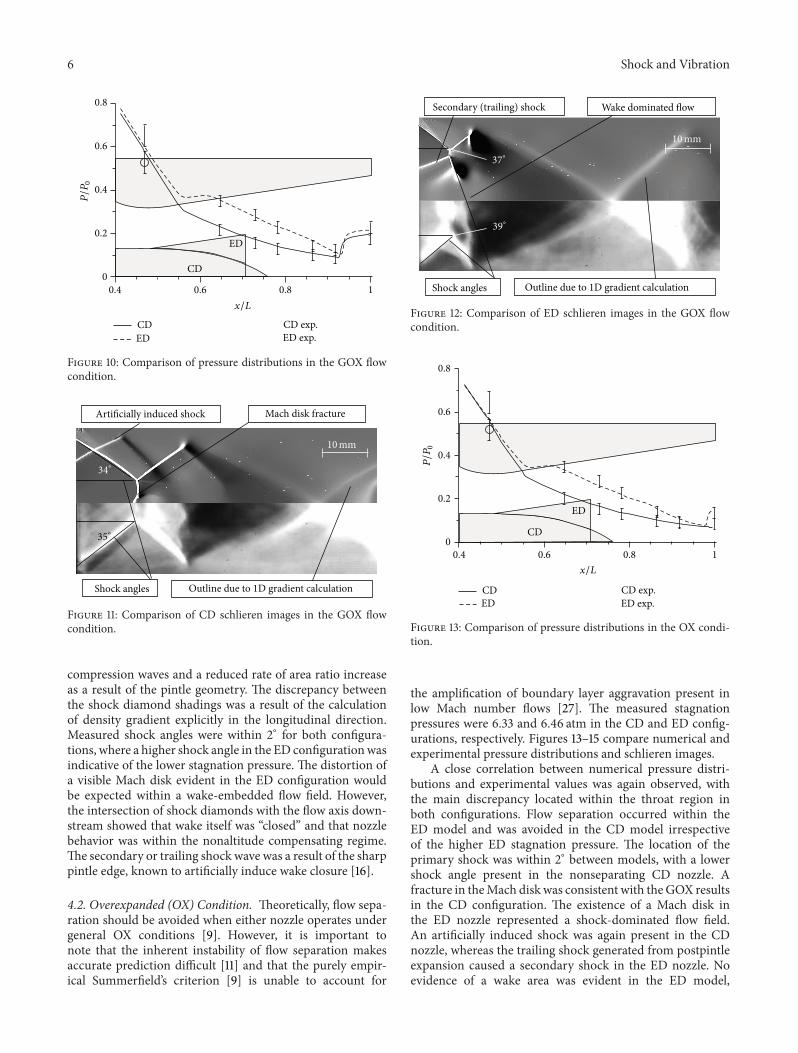

International Journal of
RotatingMachinery
Hindawi Publishing Corporationhttpwwwhindawicom Volume 2014
Hindawi Publishing Corporation httpwwwhindawicom
Journal ofEngineeringVolume 2014
Hindawi Publishing Corporationhttpwwwhindawicom Volume 2014
Mechanical Engineering
Advances in
Hindawi Publishing Corporationhttpwwwhindawicom Volume 2014
Civil EngineeringAdvances in
Hindawi Publishing Corporationhttpwwwhindawicom Volume 2014
Distributed Sensor Networks
International Journal of
The Scientific World JournalHindawi Publishing Corporation httpwwwhindawicom Volume 2014
SensorsJournal of
Hindawi Publishing Corporationhttpwwwhindawicom Volume 2014
Advances inOptoElectronics
Hindawi Publishing Corporation httpwwwhindawicom
Volume 2014
Submit your manuscripts at httpwwwhindawicom
RoboticsJournal of
Hindawi Publishing Corporationhttpwwwhindawicom Volume 2014
VLSI Design
Hindawi Publishing Corporationhttpwwwhindawicom Volume 2014
Hindawi Publishing Corporationhttpwwwhindawicom Volume 2014
Shock and Vibration
Acoustics and VibrationAdvances in
Hindawi Publishing Corporationhttpwwwhindawicom Volume 2014
Hindawi Publishing Corporationhttpwwwhindawicom Volume 2014
Electrical and Computer Engineering
Journal of
Modelling amp Simulation in EngineeringHindawi Publishing Corporation httpwwwhindawicom Volume 2014
Hindawi Publishing Corporationhttpwwwhindawicom Volume 2014
Active and Passive Electronic Components
Hindawi Publishing Corporationhttpwwwhindawicom Volume 2014
Chemical EngineeringInternational Journal of
Control Scienceand Engineering
Journal of
Hindawi Publishing Corporationhttpwwwhindawicom Volume 2014
Antennas andPropagation
International Journal of
Hindawi Publishing Corporationhttpwwwhindawicom Volume 2014
Hindawi Publishing Corporationhttpwwwhindawicom Volume 2014
Navigation and Observation
International Journal of