analysis and implementation of anfis-based rotor position
TRANSCRIPT
564 Journal of Power Electronics, Vol. 16, No. 2, pp. 564-571, March 2016
http://dx.doi.org/10.6113/JPE.2016.16.2.564
ISSN(Print): 1598-2092 / ISSN(Online): 2093-4718
JPE 16-2-17
Analysis and Implementation of ANFIS-based Rotor Position Controller for BLDC Motors
C. Navaneethakkannan† and M. Sudha*
†Department of Electrical and Electronics Engineering, Pavai College of Technology, Namakkal, Tamilnadu, India *Department of Electronics and Communication Engineering, Hindustan College of Engineering & Technology,
Coimbatore, Tamilnadu, India
Abstract
This study proposes an adaptive neuro-fuzzy inference system (ANFIS)-based rotor position controller for brushless direct current (BLDC) motors to improve the control performance of the drive under transient and steady-state conditions. The dynamic response of a BLDC motor to the proposed ANFIS controller is considered as standard reference input. The effectiveness of the proposed controller is compared with that of the proportional integral derivative (PID) controller and fuzzy PID controller. The proposed controller solves the problem of nonlinearities and uncertainties caused by the reference input changes of BLDC motors and guarantees a fast and accurate dynamic response with an outstanding steady-state performance. Furthermore, the ANFIS controller provides low torque ripples and high starting torque. The detailed study includes a MATLAB-based simulation and an experimental prototype to illustrate the feasibility of the proposed topology.
Key words: ANFIS controller, BLDC motor, Fuzzy PID controller, MATLAB/Simulink, PID controller
I. INTRODUCTION
Brushless direct current (BLDC) motors have occupied a wide spectrum of applications for variable speed drives because of their simplicity and versatility of control. In the past decade, nonlinear and adaptive control methods have been extensively used to control BLDC motor drives [1]-[5]. The rotor position and speed control of BLDC motors are important in robotics, as well as in servo applications.
Many controllers have been developed for BLDC motors because of their simplicity, clear functionality, and easy implementation. For example, the proportional integral (PI) controller was developed for the speed control of BLDC motors [6]. However, the PI controller entails a large overshoot and large settling time. The proportional–integral–derivative (PID) controller is widely used in many control applications because of its simplicity and effectiveness. However, it is not effective in cases of system uncertainty, i.e., parameter variations and external disturbance. Hence,
research attention has shifted to the robustness of controllers [7]-[9]. In particular, the problem associated with the PID controller is resolved with artificial intelligent techniques.
Fuzzy systems use knowledge expressed in the form of linguistic rules. Thus, they offer the possibility of implementing expert human knowledge and experience. Hence, fuzzy logic control serves as a good tool to deal with complicated, nonlinear, and ill-defined systems. However, this tool lacks a systematic methodology in terms of its design, and the tuning of membership function parameters is time consuming [10]-[12].
In recent years, artificial neural networks (ANNs) have gained wide attention in control applications because ANN processes are independent of human intervention and expert experiences. However, ANNs still feature certain restrictions, such as slow speed of convergence, local minima, and large amount of network computation [13], [14]. A hybrid approach was adopted in the design of speed controllers [15]-[18]. In this approach, the controller is incorporated with a neuro-fuzzy-based proportional derivative controller and a conventional integral controller. The neuro-fuzzy controller produces a significant amount of noise in control systems, and the tuning of the integral gain has a considerable effect on controller performance,
Manuscript received Jun. 25, 2015; accepted Nov. 16, 2015. Recommended for publication by Associate Editor Gaolin Wang.
†Corresponding Author: [email protected] Tel: +91-4286-293968, Fax: +91-4286-243058, Pavai College of Tech.
*Department of Electronics and Communication Engineering, Hindustan College of Engineering & Technology, India
© 2016 KIPE

Analysis and Implementation of … 565
including in the aspects of overshoot and settling time.
Adaptive neuro-fuzzy inference systems (ANFIS) overcome the shortcomings of fuzzy logic control and neural networks. These systems represent a class of ANNs that are based on fuzzy inference systems. As ANFIS integrate both neural networks and fuzzy logic principles, they feature the advantages of such tools in a single structure. An ANFIS-based controller was designed for BLDC motors [19]-[21], but its speed response exhibits high rise time, high settling time, and large steady-state errors. An emotional learning algorithm was developed on the basis of an ANFIS controller [22]. This emotional learning algorithm utilizes the proportional derivative controller function and modifies the output layer gain of the neuro-fuzzy controller.
However, the tuning of proportional and derivative gains results in large overshoot, large settling time, and high steady-state errors in system performance.
The drawbacks/disadvantages of existing works are as follows. (a) At steady-state conditions, the operation oscillates around the optimum point. (b) The speed control performance of motors is affected by parameter variations and nonlinearities.
The settling time of responses and the proper selection of a rule base in fuzzy control strategies are existing parameters that do not yield good results. Specifically, responses do not quickly reach the final steady-state value.
In the present work, a sincere attempt is made to reduce the settling time of responses and accelerate the rotor positioning of such responses by designing an efficient controller using the ANFIS control strategy, which is the main contribution of this study.
For the proposed ANFIS-based BLDC rotor position controller, the initial input–output membership functions and 49 rules are constructed with the fuzzy inference system. The ANFIS toolbox in MATLAB is used to design the proposed ANFIS controller and is integrated with the Simulink toolbox for the simulation analysis. The performance of the proposed rotor position controller is compared with that of PID and fuzzy PID controllers for BLDC motors under different operating conditions. The proposed controller is also experimentally verified.
The structure of this research work is organized in the following sequence. Section I offers a brief review of the related literature. Section II shows the mathematical modeling of a BLDC motor. Section III presents the design of the proposed ANFIS controller. Section IV provides the simulation results and its discussion. Section V reports the experimental results and discusses the BLDC motor. Section VI outlines the concluding remarks.
II. MATHEMATICAL MODEL OF BLDC MOTOR
We assume that a BLDC motor is connected to the output of an inverter and that inverter input terminals are attached to a constant supply voltage. We also assume the absence of power losses in the inverter and the star connection of the three-phase motor winding. The BLDC motor in this work is a surface-mounted non-salient pole permanent magnet (PM) synchronous machine with a trapezoidal flux distribution in the air gap. This type of motor is attractive in servo and/or variable speed applications because it can produce a torque characteristic similar to that of a PM DC motor while avoiding the problems of brush failure and mechanical commutation.
The voltage equation across the motor winding for a symmetrical winding and balanced system is presented below.
By applying Kirchhoff’s voltage law for three-phase stator loop winding circuits, the mathematical model can be represented by Equs. (1)–(3).
ac
acb
aba
aaaa edt
diM
dt
diM
dt
diLiRV (1)
bc
bca
bab
bbbb edt
diM
dt
diM
dt
diLiRV (2)
cb
cba
cac
cccc edt
diM
dt
diM
dt
diLiRV
(3)
where Va, Vb, and Vc denote the phase voltages of the motor; Ra, Rb, and Rc represent the stator winding resistances; ia, ib, and ic signify the phase currents of the motor; La, Lb and Lc denote the self-inductances of the motor; and Mab, Mac, Mba, Mbc, Mca, and Mcb are the mutual inductances between stator windings.
The mathematical model of the BLDC motor can be represented by Equ. (4) in matrix form:
ccbca
bcbba
acaba
LMM
MLM
MML
dt
d
c
b
a
i
i
i
=
c
b
a
V
V
V
-
c
b
a
R
R
R
00
00
00 -
c
b
a
e
e
e
(4)
The electromechanical torque is expressed as
Lrr
em TBdt
dJT
(5)
where J, B, and ωr denote the moment of inertia, frictional coefficient, and angular velocity of the motor, respectively. TL is the load torque. However, the electromagnetic torque for this three-phase BLDC motor is dependent on the current, speed, and back-EMF waveforms. Thus, the instantaneous electromagnetic torque can be represented as
)(1
ccbbaam
em ieieieT
(6)
III. PROPOSED ROTOR POSITION CONTROLLER

566 Journal of Power Electronics, Vol. 16, No. 2, March 2016
Fig. 1. ANFIS structure.
In this section, the ANFIS structure for the rotor position
controller, the design steps, and the training process are explained.
A. ANFIS Structure
ANFIS are used to tune existing rules with a learning algorithm on the basis of a collection of training data. The ANFIS structure is shown in Fig. 1.
Layer 1: (Input Layer) Every node i in this layer is an adaptive node with a node function, as shown in Equs. (7) and (8).
)(,1
eAL ii , for i=1, 2……j (7)
)(,1
eBL ii , for i=1, 2……j (8)
where e (or ) is the input node i and Ai (or Bi) is a
linguistic label associated with this node. Layer 2: (Fuzzification Layer) Every node in this layer is a
fixed node labeled Π, whose output is the product of all incoming signals. The output node equation of this layer is given in Eq. (9).
)()(,2ei BeAWL iii for i = 1, 2 … j2 (9)
The membership functions considered for A and B are triangular-shaped functions.
Layer 3: (Rule Layer) Every node in this layer is a fixed node labeled N. The ith node calculates the ratio of the firing strength of the ith rule to the sum of the firing strengths of all the rules. The node equation of this layer is given in Equ. (10).
j
l l
lli
WWWL 2
1
,3
(10)
Layer 4: (Defuzzification Layer) Every node i in this layer is an adaptive node with a node function, as shown in Eq. (11).
rqpWfWL iiililiee
,4 (11)
where Wl is a normalized firing strength from Layer 3 and (pi, qi, ri) is the parameter set of this node.
Layer 5: (Output Layer) The single node in this layer is a fixed node labeled Σ, which computes the overall output as
Fig. 2. Block diagram of the ANFIS controller.
the summation of all incoming signals. It is represented in Equ. (12).
j
jij
l l
il
ii li
W
fWfWL 2
2
1
1,5
21
(12)
B. Design of ANFIS Controller
The design of the ANFIS controller for BLDC motors is explained in this section.
Step 1: Selection of input The rotor position error (e) and rate of change of error
( e) are given as inputs to the ANFIS controller.
Step 2: Selection of linguistic variables for the inputs The following linguistic variables are used to describe the
input variables: Negative Big (NB), Negative Small (NS), Zero (Z), Positive Small (PS), and Positive Big (PB).
Step 3: Selection of membership functions for the inputs Gaussian membership functions are used to define the
degree of membership of the input variables. Step 4: Selection of fuzzy model for the ANFIS controller A first-order fuzzy model Sugeno (T-S) is chosen in this
design because of its computational efficiency. Step 5: Preparation of training data pairs for the ANFIS
controller
The rotor position error (e), rate of change of error ( e),
and control signal are taken as training data pairs for the ANFIS controller.
Step 6: Optimization of premises and consequent parameters of the ANFIS controller
C. Training Process of ANFIS Controller
For the training process, the collection of training data pairs is the important step in the design of the ANFIS controller. Fig. 2 shows the block diagram of the ANFIS controller.
The ANFIS controller is modeled through the input and output data of the fuzzy PID controller. To prevent the system from probable saturation conditions, the input–output

Analysis and Implementation of … 567
Fig. 3. Training data for the ANFIS controller.
Fig. 4. Initial membership function for error (e).
Fig. 5. Initial membership function for rate of change of error ( ).
data set is processed through a closed loop using a fuzzy PID controller. The input error signal (e) and rate of change of
error ( e) of the BLDC motor are used as inputs to the
ANFIS controller. The training processes are performed using hybrid learning
methods, as shown in Fig. 3. The initial membership functions for the error and the rate
of change of error are shown in Figs. 4–5. After the initialization of the membership functions, the
training process is initiated. Once the training process is completed, the ANFIS controller is ready for testing with training data. The implementation of training data with test data is shown in Fig. 6.
Fig. 6. Testing with training data.
Fig. 7. Proposed ANFIS structure for the rotor position controller.
Fig. 7 shows the proposed ANFIS model structure, which
consists of five layers. The first layer is the input layer. The second layer is the input membership function layer. The third layer is the rule layer, in which the inputs and outputs are linked with the AND operator. The fourth layer is the output membership function layer. The last layer is the output layer, which sums up all the inputs from the previous layer.
IV. SIMULATION RESULTS AND DISCUSSION
The rotor position, error, control signal, torque, and speed of the brushless motor are measured and analyzed by using the proposed controller, fuzzy PID controller, and PID controller. The parameters of the BLDC motor are shown in Table I, and its performance is obtained via simulation in MATLAB/Simulink 10.
The following gain parameters of the PID controller are determined by using the modified Ziegler Nichols tuning method: p = 0.2051, i = 1/0.0020, and = 0.0026, where Kp, Ki, and Kd are the proportional gain, integral gain, and derivative gain, respectively.
In the case of the fuzzy PID controller, the proportional, integral, and derivative (Kp, Ki, Kd) gains of the PID controller are adjusted according to fuzzy logic. The self- tuning of each parameter of the PID controller involves 49 rules.

568 Journal of Power Electronics, Vol. 16, No. 2, March 2016
TABLE I
MOTOR SPECIFICATIONS Rated power
Rated torque
Rated speed
Rated current
Voltage
60 W
0.5 N·m
1,500 rpm
3 Amps
40 V DC
Fig. 8. PID-controlled BLDC motor with sinusoidal input.
In the case of the ANFIS controller, 120 epochs are
considered for training. The input variables e and Δe both have 3 membership functions. The number of rules is then determined as 9 (3 × 3 = 9). The triangular membership function is used for the two input variables; thus, it is specified by two parameters.
Therefore, the ANFIS used in the present study contains 39 fitting parameters, 12 (2 × 3 + 2 × 3 = 12) of which are the premise parameters and 27 (3 × 9 = 27) of which are the consequent parameters. Furthermore, the input and output parameters are optimized by using the back-propagation algorithm and least squares estimation method, respectively.
A. Comparison of Various Controllers for Sinusoidal Input
A simulation is carried out for the sinusoidal input with amplitude 2Π radian, which features a frequency of 0.5 Hz and a load torque that is kept constant at 0.12 N-m. The simulation results of the rotor position response of the BLDC motor with the PID controller, fuzzy PID controller, and proposed ANFIS controller are shown in Figs. 8–10.
Fig. 8 shows that the control signal generated by the PID controller features numerous oscillations (more than 0.25 s) and affects the rotor position tracking performance of the system. However, the torque waveform exhibits small ripples. Fig. 9 indicates that the control signal provided by the fuzzy PID controller is undesirable (nearly 0.2 s) because of the involvement of a large number of parameters in defining the fuzzy rule base. The torque waveform also exhibits several ripples.
Fig. 9. Fuzzy PID-controlled BLDC motor with sinusoidal input.
Fig. 10. ANFIS-controlled BLDC motor with sinusoidal input.
Fig. 10 indicates that the control signal provided by the ANFIS controller is very low. No oscillation problem is observed, and the accuracy increases with the proposed scheme. Moreover, the torque and system are stable.
B. Comparison of Various Controllers for Ramp Input
A simulation is carried out for the ramp input with an amplitude 2Π radian, which features a frequency of 0.5 Hz and a load torque that is kept constant at 0.12 N-m. The simulation results of the rotor position response of the BLDC motor with the PID controller, fuzzy PID controller, and proposed ANFIS controller are shown in Figs. 11–13.
Fig. 11 shows that the control signal of the PID controller exhibits some oscillations (more than 0.5 s) and that the rotor position control of the BLDC motor is considerably weak. The speed of the BLDC motor also features numerous oscillations.
Fig. 12 reveals that the control signal of the fuzzy PID controller features numerous oscillations (nearly 0.2 s) and that the rotor position control of the BLDC motor is considerably weak. The speed and torque of the BLDC motor
Analysis and Implementation of … 569
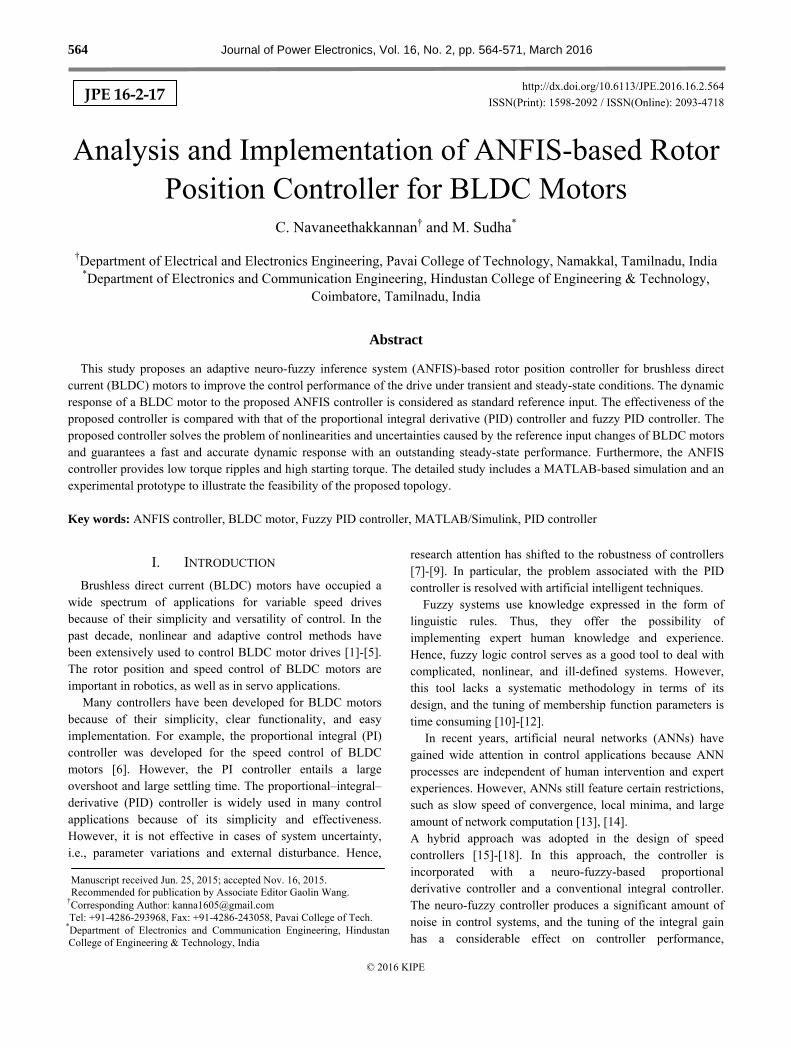
Fig. 11. PID-controlled BLDC motor with ramp input.
Fig. 12. Fuzzy PID-controlled BLDC motor with ramp input.
Fig. 13. ANFIS-controlled BLDC motor with ramp input.
also features several oscillations because of the involvement of a large number of parameters in defining the fuzzy rule base.
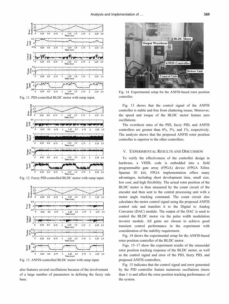
Fig. 14. Experimental setup for the ANFIS-based rotor position controller.
Fig. 13 shows that the control signal of the ANFIS controller is stable and free from chattering issues. Moreover, the speed and torque of the BLDC motor feature zero oscillations.
The overshoot rates of the PID, fuzzy PID, and ANFIS controllers are greater than 4%, 3%, and 1%, respectively. The analysis shows that the proposed ANFIS rotor position controller is superior to the other controllers.
V. EXPERIMENTAL RESULTS AND DISCUSSION
To verify the effectiveness of the controller design in hardware, a VHDL code is embedded into a field programmable gate array (FPGA) device (FPGA Xilinx Spartan 3E kit). FPGA implementation offers many advantages, including short development time, small size, low cost, and high flexibility. The actual rotor position of the BLDC motor is then measured by the count circuit of the encoder and then sent to the central processing unit with a motor angle tracking command. The count circuit also calculates the motor control signal using the proposed ANFIS control rule and transfers it to the Digital to Analog Converter (DAC) module. The output of the DAC is used to control the BLDC motor via the pulse width modulation inverter module. All gains are chosen to achieve good transient control performance in the experiment with consideration of the stability requirement.
Fig. 14 shows the experimental setup for the ANFIS-based rotor position controller of the BLDC motor.
Figs. 15–17 show the experiment results of the sinusoidal rotor position tracking response of the BLDC motor, as well as the control signal and error of the PID, fuzzy PID, and proposed ANFIS controllers.
Fig. 15 indicates that the control signal and error generated by the PID controller feature numerous oscillations (more than 1 s) and affect the rotor position tracking performance of the system.

570 Journal of Power Electronics, Vol. 16, No. 2, March 2016
Fig. 15. Sinusoidal rotor position tracking response, control signal, and error of the PID controller.
Fig. 16. Sinusoidal rotor position tracking response, control signal, and error of the fuzzy PID controller.
Fig. 17. Sinusoidal rotor position tracking response, control signal, and error of the proposed ANFIS controller.
As shown in Fig. 16, the performance of the parameters, such as the tracking response, control signal, and error (less than 1 s), is improved with the fuzzy PID controller in comparison with the PID controller.
As shown in Fig. 17, the performance of the parameters provided by the ANFIS controller is desirable and smooth.
No chattering problem is observed, and the control accuracy (0.2 s) increases with the proposed ANFIS control scheme.
TABLE II
COMPARISON OF CONVENTIONAL AND PROPOSED CONTROLLERS S. No Controller Settling
Time of Error
Signal (s)
Settling Time of Control
Signal (s)
THD in Torque
Waveform (%)
1. PID
Controller 0.25 0.32 28.61
2. Fuzzy PID
Controller 0.31 0.24 18.25
3. ANFIS
Controller 0.19 0.12 7.92
Table II provides the comparison of the conventional and
proposed controllers and reveals that the performance of the proposed ANFIS controller is superior to that of the other controllers.
VI. CONCLUSION
An ANFIS-based rotor position controller is implemented on a BLDC motor. The superiority of the proposed controller is observed and discussed through simulations and experiments. The parameters of the brushless motor are measured and analyzed with the proposed ANFIS, fuzzy PID, and PID controllers. The dynamic response of the proposed controller is obtained and analyzed for different inputs. As indicated by the dynamic response, torque ripple is significantly reduced, and no chattering problem is observed because of the control signal with the proposed rotor position controller. Moreover, the proposed ANFIS controller improves system performance under transient and steady-state conditions in comparison with other controllers.
REFERENCES
[1] J. Y. Hung, W. Gao, and J. C. Hung, “Variable structure control: a survey,” IEEE Trans. Ind. Electron., Vol. 40, No. 1, pp. 2-22, Feb. 1993.
[2] E. Cerruto, A. Consoli, A. Raciti, and A. Testa, “ A robust adaptive controller for PM motor drives in robotic application,” IEEE Trans. Power Electron., Vol. 10, No. 1, pp. 62-71, Jan. 1995.
[3] N. Hemati, J. S. Thorp, and M. C. Leu, “Robust nonlinear control of brushless dc motors for direct drive robotic applications,” IEEE Trans. Ind. Electron., Vol. 37, No. 6, pp. 460-468, Dec. 1990.
[4] U. Neethu and V. R. Jisha, “Speed control of brushless DC motor: a comparative study,” in IEEE International Conference on Power Electronics, Drives and Energy Systems(PEDES), pp. 1-5, Dec. 2012.
[5] A. Sathyan, N. Milivojevic, Y.-J. Lee, and M. Krishnamurthy, “An FPGA based novel digital PWM control scheme for BLDC motor drives,” IEEE Trans. Ind. Electron., Vol. 56, No. 8, pp. 3040-3049, Aug. 2009.
[6] Metin Demirtas, “Off-line tuning of a PI speed controller for a permanent magnet brushless DC motor using DSP,”

Analysis and Implementation of … 571
Energy Conversion and Management, Vol. 52, No. 1, pp. 264-273, Jan. 2011.
[7] A. S. O. Al-Mashakbeh, “Proportional integral and derivative control of brushless DC motor,” European Journal of Scientific Research, Vol. 35, No. 2, pp. 198-203, Aug. 2009.
[8] J. C. Basilio and S. R. Matos, “Design of PI and PID controllers with transient performance specification,” IEEE Trans. Edu., Vol. 45, No. 4, pp. 364-370, Nov. 2002.
[9] R. Arulmozhiyal and K. Baskaran, “Implementation of fuzzy PI controller for speed control of IM using FPGA,” Journal of Power Electronics, Vol. 10, No. 1, pp. 65-71, 2010.
[10] S. V. Wadnerkar, M. M. Bhaskar, T. R. Das, and A. D. RajKumar, “A new fuzzy logic based modeling and simulation of a switched reluctance motor,” Journal of Electrical Engineering & Technology, Vol. 5, No. 2, pp. 276-281, Jun. 2010.
[11] N. S. Kumar and C. S. Kumar, “Design and implementation of adaptive fuzzy controller for speed control of brushless DC motors,” International Journal of Computer Applications, Vol. 1, No. 27, pp. 46-51, Feb. 2010.
[12] M. Cunkas and O. Aydoğdu, “Realization of fuzzy logic controlled brushless DC motor drives using Matlab/Simulink,” Mathematical and Computational Applications, Vol. 15, No. 2, pp. 218-229, Aug. 2010.
[13] J. Sun, Y. Chai, C. Su, Z. Zhu, and X. Luo, “BLDC motor speed control system fault diagnosis based on LRGF neural network and adaptive lifting scheme,” Applied Soft Computing, Vol. 14, Part C, pp. 609-622, Jan. 2014.
[14] Z. Cheng, C. Hou, and X. Wu, “Global sliding mode control forb DC motors by neural networks,” in Proceedings of AICI, No. 4, pp. 3-6, 2009.
[15] M. Gokbulut, B. Dandil, and C. Bal, A hybrid neuro-fuzzy controller for brushless DC motors, Artificial Intelligence and Neural Networks, Springer, Vol. 3949, pp. 125-132, 2006.
[16] A. Rubaai, M. J. Castro-Sitiriche, and A. R. Ofoli, “Design and implementation of parallel fuzzy PID controller for high-performance brushless motor drives: an integrated environment for rapid control prototyping,” IEEE Trans. Ind. Appl., Vol. 44, No. 4, pp. 1090-1098, Jul./Aug. 2008.
[17] M. J. Er and Y. Gao, “Robust adaptive control of robot manipulators using generalized fuzzy neural networks,” IEEE Trans. Ind. Electron., Vol. 50, No. 3, pp. 620-628, Jun. 2003.
[18] C.-H. Lee and C.-C. Teng, “Identification and control of dynamic systems using recurrent fuzzy neural Networks,” IEEE Trans. Fuzzy Syst., Vol. 8, No. 4, pp. 349-366, Aug. 2000.
[19] Q. C. Zhang and M. Jiang, “Adaptive neuro-fuzzy control of BLDCM based on back-EMF,” Journal of Computer Information Systems, Vol. 7, No. 12, pp. 4560-4567, Oct. 2011.
[20] V. M. Varatharaju, B. Mathur, and Udhayakumar, “Adaptive controllers for permanent magnet brushless DC motor drive system using adaptive network based fuzzy interference system,” American Journal of Applied Sciences, Vol. 8, No. 8, pp. 810-815, Aug. 2011.
[21] K. Premkumar and B. V. Manikandan, “Adaptive neuro-fuzzy inference system based speed controller for brushless DC motor,” Neurocomputing, Vol. 138, No.1, pp. 260-270, Aug. 2014.
[22] A. H. Niasar, A. Vahedi, and H. Moghbelli, “Speed
control of a brushless DC motor drive via adaptive neuro fuzzy controller based on emotional learning algorithm,” in Proceedings of the 8th International Conference on Electrical Machines and Systems(ICEMS), Vol. 1, pp. 230-234, Sep. 2005.
C. Navaneethakkannan was born in Tamilnadu, India. He received his B.E. degree in Electrical and Electronics Engineering from Anna University, Chennai, India, in 2006, and his M.E. degree in Embedded System Technologies from Anna University, Coimbatore, India, in 2010. Since 2010, he has been an Assistant
Professor in the Department of Electrical and Electronics Engineering, Pavai College of Technology, Namakkal. His current research interests include intelligent controllers and BLDC motor drives.
M. Sudha was born in Tamilnadu, India. She received her B.E. and M.E. degrees in Electrical Engineering from Bharathiar University, Tamilnadu, India, in 1993 and 2004, respectively. She received her Ph.D. degree in Embedded Systems from Anna University, Chennai, India, in 2009. Since 2014, she has been a Professor and Head of
the Department of Electronics and Communication Engineering, Hindustan College of Engineering and Technology, Coimbatore. Her current research interests include embedded systems, control systems, and power electronics.