an overview of the nasa f-18 high alpha research€¦ · an overview of the nasa f-18 high alpha...
TRANSCRIPT

NASA Technical Memorandum 4772
An Overview of the NASA
F- 18 High Alpha ResearchVehicle
Albion H. Bowers, Joseph W. Pahle, R. Joseph Wilson,
Bradley C. Flick, and Richard L. Rood
October 1996
https://ntrs.nasa.gov/search.jsp?R=19970003009 2020-07-07T17:15:02+00:00Z


NASA Technical Memorandum 4772
An Overview of the NASA
F- 18 High Alpha ResearchVehicle
Albion H. Bowers, Joseph W. Pahle, R. Joseph Wilson,
Bradley C. Flick, and Richard L. Rood
Dryden Flight Research Center
Edwards, California
National Aeronautics and
Space Administration
Office of Management
Scientific and TechnicalInformation Program
1996


AN OVERVIEW OF THE NASA F-18 HIGH ALPHA RESEARCH VEHICLE
Albion H. Bowers
Joseph W. Pahle
R. Joseph Wilson
Bradley C. FlickRichard L. Rood
NASA Dryden Flight Research CenterEdwards, CA
ABSTRACT
This paper gives an overview of the NASA F- 18 High Alpha Research Vehicle. The three flight
phases of the program are introduced, along with the specific goals and data examples taken during
each phase. The aircraft configuration and systems needed to perform the disciplinary and
interdisciplinary research are discussed. "The specific disciplines involved with the flight research
are introduced, including aerodynamics, controls, propulsion, systems, and structures. Decisions
that were made early in the planning of the aircraft project and the results of those decisions are
briefly discussed. Each of the three flight phases corresponds to a particular aircraft configuration,
and the research dictated the configuration to be flown. The first phase gathered data with the
baseline F-18 configuration. The second phase was the thrust-vectoring phase. The third phase
used a modified forebody with deployable nose strakes. Aircraft systems supporting these flights
included extensive instrumentation systems, integrated research flight controls using flight control
hardware and corresponding software, analog interface boxes to control forebody strakes, a thrust-
vectoring system using external postexit vanes around axisymmetric nozzles, a forebody vortex
control system with strakes, and backup systems using battery-powered emergency systems and a
spin recovery parachute.
NOMENCLATURE
ANSER
CRAFT
DPRAM
FCC
FS
HAIRRY
HANG
HARV
actuated nose strakes for enhanced rolling
control power, robustness, agility, and flying qualities tradeoffs
dual-port random access memory
flight control computer
fuselage station, in.
High-Angle-of-Incidence Requirements for Roll and Yaw
High-Alpha Nosedown Guidelines
High Alpha Research Vehicle

HATP
KEAS
LEX
MATV
MDA
NACA
NASA
OBES
PGME
RAV
RFCS
SRC
STEMS
TVCS
VISTA
0
High-Alpha Technology Program
knots equivalent airspeed
leading-edge extension
Multi-Axis Thrust Vectoring
McDonnell Douglas Aerospace
National Advisory Committee on Aeronautics
National Aeronautics and Space Administration
on-board excitation system
propylene glycol monomethyl ether
remotely augmented vehicle
research flight control system
spin recovery chute
standard test evaluation maneuvers set
thrust-vectoring control system
Variable-Stability In-Flight Simulator Test Aircraft
angle of attack, deg
radial nose angle, deg
INTRODUCTION
Interest in high-angle-of-attack flight has increased in recent years. High-angle-of-attack
research has progressed from stall characteristics to spin resistance and is now in the area of
poststall agility. To support this recent interest, NASA has developed the High-Alpha Technology
Program (HATP). One of the objectives of this program is flight validation of ground-based design
methodologies, and a modified F-18 aircraft was used to this end. This aircraft is called the NASA
F-18 High Alpha Research Vehicle (HARV).
History: Missile Platforms to Departures to Air Combat Maneuvering and Agility
Research into high-angle-of-attack flight has waned and revived over the history of aviation
(fig. 1).t,2 High-angle-of-attack research has also changed over the years. Initially, high-angle-of-
attack research was only concerned with stall characteristics. Research then evolved to departure
and spin characteristics, and now concentrates on exploring the poststall region of the high-angle-
of-attack envelope. Early jet aircraft emphasized high performance with classical metrics,
2

primarily speedandaltitude.Theseaircraftweredesignedwith little regardfor flying qualitiesathighangleof attack,t_, other than minimal attention to departure resistance. Aircraft that began as
gun platforms moved towards missile platforms. The F-1 O0 Super Sabre, the F-104 Starfighter, and
the F-4 (n6e F-110) Phantom II aircraft are examples of this trend.
High c_research
1900 1920 1940 1960 1980Year
Figure 1. Interest level of high-angle-of-attack activity.
I2OO0
960687
With a shift in emphasis back to air combat maneuvering from nonmaneuvering missile
platforms during the Vietnam conflict, 3 initial emphasis shifted back to air combat training with
existing aircraft. Development of aircraft to take advantage of high-or flight began later. Advances
made in fly-by-wire and fully digital flight controls allowed some degree of confidence in using
some of the high-t_ regime. The early examples of these aircraft were the F-16 and F/A-18 (n6e
YF-17), and today are the JAS-39 Gripen, the Euro-Fighter 2000, and the F-22 Lightning aircraft.
NASA Formulation of the High-Alpha Technology Program
With this recent interest in high-a flying qualities in the aircraft community, NASA has
emphasized high-t_ research as well, although NASA has always been interested in high-t_
flight. 4-7 Research conducted by NASA includes aileron rudder interconnects, thrust vectoring,
and unconventional control surfaces to allow greater enhancements in high-or flight dynamics
and solve classical problems such as wing rock, departure, nose slice, and high-or pitching-
moment discrepancy. 8'9 Ground-based research on thrust vectoring has demonstrated the promise
of being able to exert moments in corners of the envelope where aerodynamic forces and control

powerarevery low. Useof forebodyflows for aircraftcontrol athigh _ wasalsoshownto havegreatpotential.1°
Threehigh-orflight programsstartedin the 1980's:the X-31A researchaircraft,l_ the F-16Variable-Stability In-Flight Simulator Test Aircraft (VISTA) Multi-Axis Thrust Vectoring(MATV) project,12andtheNASA-sponsoredHATP usingtheHARV. 4'5'7'13-17 Stated objectives of
these programs were, respectively, demonstration of enhanced fighter maneuverability at poststall
angles of attack with a controlled-configuration vehicle design; retrofit of thrust vectoring on an
existing design to evaluate tactical usage of such a system; and a pure high-t_ research program to
understand basic high-o_ aerodynamics, possible control law synthesis, innovative control
effectors, inlet and engine integration research, and possible expansion of design guidelines.
All of the NASA aeronautics centers participated in the HATP, and the program was directed
by a representative steering committee (fig. 2). NASA Ames Research Center contributed
computational fluid dynamics and their '80- by 120-ft wind-tunnel facility. 18-21 NASA Langley
Research Center worked with subscale wind-tunnel testing, advanced control law synthesis, and
computational fluid dynamics. 1°.22-26NASA Lewis Research Center worked on inlet and engine
integration. 27'28 NASA Dryden Flight Research Center conducted the flight research with theF- 18 HARV.
Headquarters
High Alpha TechnologyProgram Manager
Langley I
Ground Research
Techn cal Lead ]
IEx erna':e r'°'dynam'ceII
Technical Steering
Committee
Langley
Ames
Lewis
Headquarters
Dryden
I
Dryden JFlight Research
Vehicle Manager
Lewis
Inlet Aerodynamics
960688
Figure 2. High-angle-of-attack technology program organization.
The aircraft selected was the full-scale development F-18 Ship 6, now called the NASA F-18
HARV. 7'17'29 Prior to use for NASA research, this F-18 airframe had been used for the high-o_ and
spin testing of the F- 18 configuration. To gain more redundancy than exists in fleet F/A- 18 aircraft,
a battery-powered emergency system had been installed in this particular airframe. This aircraft
had also been previously fitted for a spin recovery chute (SRC). These special modifications for
this particular airframe led to its selection. The aircraft was subsequently modified extensively to
4

include thrust vectoring, a unique instrumentationsystem,unique aircraft systems,additionalemergencysystems,amodifiedflight controlcomputer,29andlater, forebodystrakes.
VEHICLEAND SYSTEMDESCRIPTION
The aircraft configurationis describedbelow.The systemsusedon the HARV enabledtheaircraftto performdifferentresearchmissions.Manyof thesesystemsareintroducedhere,suchastheSRC,theemergencypowersystems,thethrust-vectoringcontrolsystem(TVCS), theresearchflight control system(RFCS),the forebody strakesystem,the simulation,and the remotelyaugmentedvehicle(RAV) system.
HighAlphaResearchVehicle
TheHARV hashadthreeconfigurations:thebaselineF-18configuration,thethrust-vectoringinstallationconfiguration,andtheadditionalforebodyvortex-flow control configuration(fig. 3).These three configurationscorrespondto the approximatephasesof the flight tests and arediscussedlater in the paper.This largeandambitiousflight testmatrixwasonly possiblewith aphasedapproachto theprogram.TheHARV is afull-scaledevelopmentairframeof theF/A-18Aaircraftandis atwin-engine,single-place,fighter/attackaircraft.Theearlyaircraft usedtheF-18
EC8962-1
(a)Phaseone,noTVCS,noANSERsystem.
Figure3. HARVconfigurationfor thethreephasesof theflight program.

EC910028-9(b) Phasetwo,TVCS installed,noANSERsystem.
EC9543197-1(c) Phasethree,TVCSinstalled,ANSERsysteminstalled.
Figure3. Concluded.
type designation,of which the HARV aircraft is one.Later, the U.S. Navy changedthe typedesignationto F/A-18to alignthedesignationwith thediverserolesof fighterandattack.TheF-18aircraft was built for the U.S. Navy by McDonnell Douglas Aerospace(MDA) (St. Louis,
6
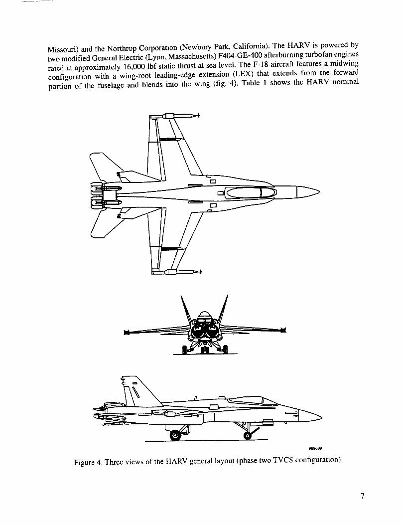
Missouri) and the Northrop Corporation (Newbury Park, California). The HARV is powered by
two modified General Electric (Lynn, Massachusetts) F41M-GE-400 afterburning turbofan engines
rated at approximately 16,000 lbf static thrust at sea level. The F-18 aircraft features a midwing
configuration with a wing-root leading-edge extension (LEX) that extends from the forward
portion of the fuselage and blends into the wing (fig. 4). Table 1 shows the HARV nominal
969689
Figure 4. Three views of the HARV general layout (phase two TVCS configuration).
7

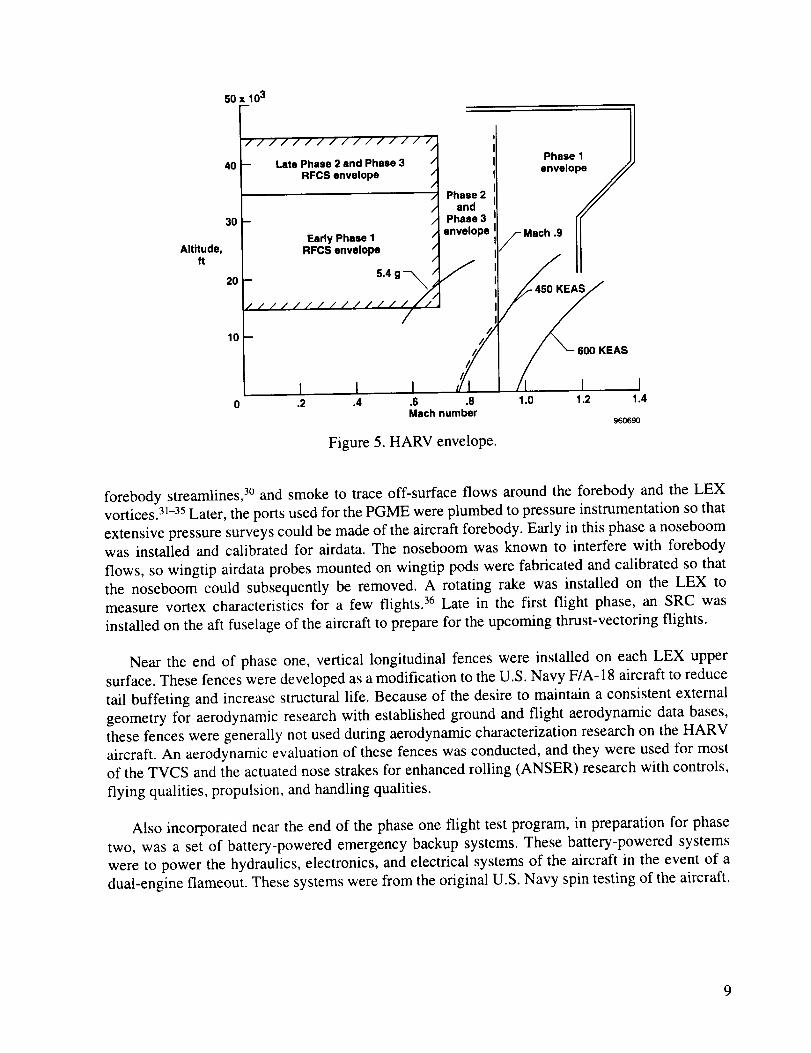
dimensions and weights. The flight envelope was also limited with the various systems on board
the aircraft (fig. 5), although with the SRC installed and the center of gravity forward of26.5 percent mean aerodynamic chord, the aircraft was not limited in o_.
Table 1. Nominal dimensions of the NASA F-18 HARV. Internal fuel
is 6480 Ibm, which corresponds to approximately 60 percent fuel.
The HARV is in the clean configuration, with landing gear retracted
and pilot and support equipment included.
Phases two
Parameter Phase one and three
Weight, Ibm 31,980 36,099
Reference wing area, ft2 400 400
Reference mean aerodynamic chord, ft 11.52 11.52
Reference span, ft 37.4 37.4
Overall length, ft 56 56
Center of gravity
Percent mean aerodynamic chord 21.9 23.8
Fuselage station 454.33 456.88
Waterline 105.24 105.35
Roll inertia, slug-ft 2 22,040 22,789
Pitch inertia, slug-ft 2 124,554 176,809
Yaw inertia, slug-ft 2 139,382 191,744
Product inertia, slug-ft a -2,039 -2,305
Wing aspect ratio 3.5 3.5
Stabilator span, ft 21.6 21.6
Stabilator area, ft 2 88.26 86.48
The HARV carries no stores or missiles and is highly instrumented for research purposes. The
wingtip launching rails and missiles were replaced with wingtip camera pods and airdata sensors.
The in-flight refueling capability and tail arresting hook were retained; 24 flights were made within-flight refueling, but the tailhook was never used.
For the first phase of the flight test program, the aircraft was flown in the baseline configuration
as described above. In this configuration, the maximum attainable trim _ was approximately 55 °,limited by the maximum aerodynamic control. Most HARV modifications were internal for this
phase of the program and consisted mostly of an extensive instrumentation system for recording
research aircraft parameters of interest. Also incorporated in this phase were onboard systems toemit an evaporating dye, propylene glycol monomethyl ether (PGME), to mark on-surface
8
Altitude,tt
50 x 103
4O
3O
20
10
//////////////// I
-- Late Phase 2 and Phase 3 /RFCS envelope /
/ Phase 2/ and/ Phase 3/ envelope/
Early Phase 1RFCS envelope
_ 5.4 g--_
//////////////_
/
I I.2 .4 1.0 1.2
/j
////
////
I #I.6 .8Mach number
Figure 5. HARV envelope.
Phase I /]
envelo_
fMaeh.9 JJ
II
_/ _ 60O KEAS
/I I
forebody streamlines, 3° and smoke to trace off-surface flows around the forebody and the LEX
vortices. 3]-35 Later, the ports used for the PGME were plumbed to pressure instrumentation so that
extensive pressure surveys could be made of the aircraft forebody. Early in this phase a noseboomwas installed and calibrated for airdata. The noseboom was known to interfere with forebody
flows, so wingtip airdata probes mounted on wingtip pods were fabricated and calibrated so that
the noseboom could subsequently be removed. A rotating rake was installed on the LEX to
measure vortex characteristics for a few flights. 36 Late in the first flight phase, an SRC was
installed on the aft fuselage of the aircraft to prepare for the upcoming thrust-vectoring flights.
Near the end of phase one, vertical longitudinal fences were installed on each LEX upper
surface. These fences were developed as a modification to the U.S. Navy F/A-18 aircraft to reduce
tail buffeting and increase structural life. Because of the desire to maintain a consistent external
geometry for aerodynamic research with established ground and flight aerodynamic data bases,
these fences were generally not used during aerodynamic characterization research on the HARV
aircraft. An aerodynamic evaluation of these fences was conducted, and they were used for most
of the TVCS and the actuated nose strakes for enhanced rolling (ANSER) research with controls,
flying qualities, propulsion, and handling qualities.
Also incorporated near the end of the phase one flight test program, in preparation for phase
two, was a set of battery-powered emergency backup systems. These battery-powered systems
were to power the hydraulics, electronics, and electrical systems of the aircraft in the event of a
dual-engine flameout. These systems were from the original U.S. Navy spin testing of the aircraft.
9

Thesecondphaseof the flight test program was centered on the TVCS. Six paddle-like vanes
were positioned, three around each engine, so that they could impinge on the exhaust flow and
create thrust vectoring. With these vanes functional, an additional 15 ° of trim o_are available to amaximum 70 ° o_.
The conventional F-18 flight control system was modified to include an RFCS and the
capability to command the thrust-vectoring vane actuators. The RFCS was an embedded computer
executing research flight control laws that could be engaged and disengaged by the pilot within a
limited envelope. The RFCS control laws and F-18 701E computer (General Electric, Lynn,
Massachusetts) control laws operate in parallel; both computed continuously throughout the flight.
The conventional F-18 control laws were used for takeoff, for landing, and as a backup in case of
RFCS failure. The second set of control laws was a research control law set. 37 The hardware to
accommodate this dual set of flight control laws resulted in one of the single largest changes ever
incorporated in F-18 flight control computers (FCCs). During this phase, the aircraft underwent a
second major downtime to make an extensive modification to instrumentation, including an inletrake in the right engine. 27
The final flight phase of the HARV project emphasized forebody vortex-flow control. A
modified forebody was fabricated at NASA Langley with mechanically actuated strakes. NASA
Langley also designed the control laws to control the forebody control surfaces. The strakes are the
aerodynamic surfaces of the ANSER system, but some extensive internal changes, both hardware
and software, were made as well. An analog interface box was required to perform fault detection
and control of the actuators for the strakes. When the RFCS was designed, the intent was to only
control the six vanes of the TVCS, but the addition of the strakes for the ANSER system requiredtwo new command paths out of the FCCs, which required the analog interface box. The control law
release was also called ANSER. NASA Ames had proposed an alternative concept using slot
blowing. 38-'4° The project could only take one concept to flight, and the NASA Langley actuated
strake was selected as a more mature technology than the other concepts.
Data Acquisition and Research Instrumentation
The instrumentation system used for data acquisition changed greatly over the course of the life
of the aircraft. The original instrumentation system provided aircraft attitudes, rates, center-of-
gravity and cockpit accelerations, angular accelerations, oc, angle of sideslip, multiple total and
static pressures, aerodynamic surface pressures, total temperature, stick and rudder-pedal forces
and positions, control surface positions, fuel quantities, strains, temperatures, and discretes such as
switch positions. Wingtip probes that provided research airdata were updated from a National
Advisory Committee on Aeronautics (NACA) probe configuration to a free-swiveling self-
aligning probe configuration, although the tip retained a similar configuration to the NACA probetip. A second instrumentation system was added to obtain 1553 bus data from the FCCs, mission
computers, inertial navigation system and other remote terminals, aerodynamic surface pressures,
aeroservoelastic accelerometers, nose and wing flush airdata sensing pressures, engine pressures,
strains, temperatures, and discretes such as nose strake interface box status bits. Thrust-vectoring
vane loads and critical temperatures were added for phase two, and additional forward fuselage
10

loads,interfaceboxparameters,andnosestrakeinstrumentationwereaddedfor thethirdphaseoftheflight program.Eachof thesesystemswastelemeteredwith no recordingonboardtheaircraft.A researchinlet rakewasinstalledin theright inlet duct (fig. 6), anda third systemwasprovidedto obtainthe inlet researchdata.In orderto avoida third telemetrystream,the third systemwasdigitally recordedonboard.
EC9341084-7
Figure6. Instrumentedinlet rakeinstalledin theright inlet (looking aft).
Maximumdatarateswereashighas2142samples/secandasmanyasnearly2000parameters.Control roomdisplayswereplannedin advanceto optimizemonitoringscans,for familiarization,andto maximizepotentialflight researchtime. Examplesshownareof the spinpage,asusedbythe missioncontroller during high-t_andhigh-yaw-ratemaneuvers(fig. 7), and the flightpathreconstructorusedby flight mechanicsresearchersto monitor aircraft motionsand stateduringparameteridentificationmaneuvers(fig. 8).42
SpinRecoveryChute
An SRC was added to the aircraft late in the first phase. This system was a significant
modification to the aerodynamics of the aircraft. The SRC system was previously used by MDA
and the U.S. Navy for the spin testing done in the full-scale development testing of the F-18. This
system was reinstalled to reduce the amount of validation required of the flight control software
for high-or flight. High-or velocity-vector rolls with thrust vectoring, which were planned, were
anticipated to appear exactly identical to spins in conventional aircraft. 42 The SRC installation was
11

50Sl
3_1,0 k !
0,0 K •
4 450--
-511
-75
RIII_T
0
g_o_Sg 1
Figure 7. Mission controller spin page display for monitoring high-or and high-yaw-rate
maneuvers.
done as further risk reduction in the event of a failure of the thrust-vectoring system and the
subsequent failure of conventional control-recovery techniques. The aircraft limitations with theSRC installed were Mach 0.9 and 600 knots equivalent airspeed (KEAS). The system was never
fired in flight, but was test-fired during a high-speed taxi test (fig. 9). Flight test during phase two
proved the aircraft could recover using control surfaces during low and oscillatory spin modes,control law down modes (reversion from RFCS control laws to 701E computer control laws) at
peak yaw rates of velocity-vector roll to simulate failures and recovery, and control law down
modes with maximum aggravated control inputs during velocity-vector rolls.
During phase three, simulation studies revealed that asymmetric strake failures at high g and
high o_ (40°-55 ° ct) resulted in unacceptable recovery characteristics. A positive strake closure
system was designed, and the SRC was retained for all of phase three. When envelope expansion
of each phase was complete, however, the SRC system was found to be of lessening importance,but no method was found where its deletion could be made, even after envelope expansion.
Operationally, the SRC consumed a great deal of time--time that could have been better spent onresearch tasks had the SRC been removed from the aircraft.
12

96oe92
Figure 8. Flightpath reconstructor as used by flight mechanics researchers during parameter
identification maneuvers.
Emergency Power Backup Systems
Battery-operated emergency power systems were installed in the aircraft at the end of phase
one in preparation for phase two. These systems were previously used in the full-scale
development spin tests, reducing certification time for the HARV application. The intent of these
systems was to continue aircraft systems operation in the event of a dual-engine flameout orunrecoverable dual-engine stalls. If called upon, the emergency power system provides power for
FCCs, mission computers, inertial systems, and airdata computers. Additionally, the batteries
power a hydraulic pump to provide hydraulic pressure to the aircraft control-surface actuators. The
system was modified from the U.S. Navy spin flight configuration by increasing battery capacity,
and power could be maintained for approximately 14 min using continuous maximum control-surface motions. At the end of phase two, the project team concluded the aircraft envelope had been
sufficiently cleared out so that the emergency system could be removed without excessive risk, and
13

EC89009-9
EC91-518-21Figure9. Spinrecoverychuteasinstalledanddemonstrated.
that theusefullife of the systemhadbeenrun. Theemergencypowersystemwasremoved.Thisdecisionwasbasedon the excellentrecordof 0 unintentionalenginestallsduring 277 high-ocflights. A totalof 383high-o_flights wasmadewith0 unintentionalenginestalls.
14

Thrust-Vectoring Control System
The TVCS was primarily a mechanical system of three high-temperature nickel steel vanes, or
paddles, installed around each engine. As existing structure and the SRC of the aircraft had to be
considered, the vanes were not equally spaced around the engines or equally sized (fig. 10).
Extensive heat shielding was required to prevent excessive temperatures from impinging on the
systems and aircraft in the aft fuselage area. These minor variations in spacing and sizing resulted
in a slight asymmetry to the thrust-vectoring effectiveness control power. 43-46This implementation
Maximum-afterburner //
nozzle 348 In2-----_ //_//_/'//_
118" AI"/////H/#///Z_ _,
i "nozzle 220 in2-.-J_l _,_/_ _ _/
103.5".. .... _""
Upper vane
_'_i \\
\\
\
_,________________,,\ 138.5"', I' I
I I
I!
I/
/
_ Lower
vane
960693
20 in.
._ _ Radius = 36 in.5.185 in./
20 in.
12.591 in.
,1Lower and
outer vanes
9.120 in. ---_
--- 15 in.
Area = 263.64 in2
Figure 10. Thrust-vectoring vane geometry,platforms.
Upper vane
20 in.
Area = 358.76 in 2
12.420 in.
960694
end view (left engine looking forward) and vane
15

of a TVCS was intended only as a research system. No effort was expended on making the system
more than a boilerplate operational system to allow research to be gathered, because maintenance
is intensive on such a system and useful life of the system was expected to be short.
With the TVCS and SRC installed, the project had to contend with a large weight and balance
problem. The installation of the TVCS increased the weight by 2200 Ibm. The addition of the SRC,
emergency systems, and ballast* increased the weight by an additional 1500 Ibm, and 419 Ibm was
added by equipment and wiring not directly related to the TVCS.
With this additional weight, the inertia values were approximately 50 percent greater than the
previous flight-tested maximum for the interdiction mission. As a result, the maximum
symmetric g allowed was reduced to 5.4 and -2.0. During asymmetric maneuvering, the aircraftwas limited to between 4.3 g and 0 g. In addition, the weight distribution acted as a pitch damper
and was perceived as a time delay to the pilot when flying exceptionally high gain tasks.
Failure in these cases was anticipated in the aft cockpit canopy sill area near fuselage station
(FS) 300, possibly hampering ejection, so instrumentation strain gages were installed andmonitored for the remainder of the program. Installation of the TVCS limited maximum speed to
450 KEAS on the HARV aircraft. These g and airspeed limitations were the results of analysis only;
no extensive flight envelope clearance was done in the program. The system might have been
capable of a much greater performance envelope than was used had there been a such requirement.
Research Flight Control System
In order to control the six new control surfaces, a modification was made to the EGGs. 7'47 The
Pace 1750A (Performance Semiconductor Corp., Sunnyvale, California) FCCs were modified to
incorporate a dual-port random access memory (DPRAM) and RFCS (fig. 11). The purpose of
the DPRAM was to pass parameters back and forth between the 701E computers and the RFCS.
The purpose of the RFCS was to allow rapid changes and reduced development time for
experimental control laws of the unique control effectors in the high-or envelope. For the most
part, the RFCS flight control software was designed to be class B software and not flight critical.
As such, the verification and validation of the RFCS flight control software was greatly
streamlined, allowing rapid changes to be effected in the event of unexpected research results.
This class B capability of the FCCs made the aircraft a very flexible and capable research tool,
where different systems could be flown and compared back-to-back with other systems on an
aircraft of a known configuration. Changes of this sort were done many times in the course of the
program, and this innovative approach and execution greatly aided in gathering timely andeffective research data. Having a dedicated research team in place that could rapidly handle
changes provided a very flexible approach to problem solving. Parts of the control law executiveand some limit functions were deemed flight critical, and thus were isolated in the software and
tested according to class A standards.
*To maintain an acceptable center of gravity, a total ballast of 893 Ibm was added to the forward fuselage.
16

Analog outto surfaces
-_- Flight control _ Analog out
laws "1..17 _ to vanes
Dual-port RAM 1 v Interface box
Research flight ___v for strakescontrol system
960695
Figure 11. Flight control computers incorporating a research flight control system.
During phase one, the 701E computers had carried the then-current fleet production
8.3.3 flight control law release by MDA. With the RFCS upgrade, the 701E computers were
updated to the new release of the fleet production MDA 10.1 F-18 release. The RFCS control laws
would be engaged within certain envelope restrictions imposed by the flight control law software.
The envelope for RFCS flight was restricted to less than Mach 0.7, a minimum altitude of
15,000 ft mean sea level, and an initial maximum altitude of 35,000 ft mean sea level that was
later expanded to 45,000 ft mean sea level. Because of potential errors in the flight software withinthe RFCS control laws, the 701E computer control laws were always retained as a backup. Any
RFCS anomalies that might threaten the aircraft would be mitigated by reverting to the 701E
computer control laws. As figure 11 shows, the basic F-18 control system retained control over all
input and output signal management functions, including commands to the thrust-vectoring vanes.When the RFCS was not engaged, the basic system commanded the vanes to a fixed, retracted
position of-10 deg. A solenoid-latched switch was installed on the instrument panel to arm the
system, and the nosewheel steering switch on the stick was selected to engage the RFCS. To
disengage, the pilot activated the paddle switch to revert to 701E computer control laws. All
control laws used a programmable fade to prevent instant gain changes. Later, the Pace 1750A
processors were upgraded to the Pace 1750AE configuration.
Research functions were also implemented in the mission computers and selectable through the
digital-display interfaces. These research functions included the synthesis of some control systemfeedbacks not available in the standard F/A-18 aircraft, as well as unique research displays used by
the HARV pilot. These displays in the head-up display included fixed reticles for tracking tasks,
vertical lines for target gross acquisitions during tracking, and displays to annunciate the aircraft
control mode. Another part of the flight software was the on-board excitation system (OBES).
Software in the OBES held preprogrammed research and envelope expansion maneuvers and could
perform frequency sweeps, doublets, or even act to degrade control power for individual or
multiple surfaces. The OBES was used for flutter envelope clearance, 48 control power research
studies, 49 and aerodynamic 41'5°-54 and control law parameter identification research. 25
Forebody Strakes
For the third and final phase in the HARV flight test project, a set of ANSER was installed on
the forebody of the HARV.I° These strakes were designed with a longitudinal hinge line to actively
17

controltheforebodyvorticesandseparationlines(fig. 12),whichallowedroll controlat higho_tobeperformed.55Thestrakesweredesignedandtestedby NASA Langleyandinstalledandflownat NASA Dryden.Control lawswerealsodesignedbyNASA Langleyto controlthestrakes.TheANSER required that two additional control-surfacecommandsbe brought from the FCCs.Initially, it wasthoughtthattheTVCS or two vaneswouldhaveto bedeactivatedbecauseof thelimited actuatoranaloginput/outputavailablefrom theFCCs.This deactivationwouldnot allowback-to-backcomparisonsof theTVCS andANSERor of an integratedANSER-TVCS mode.Finally, theFCCmotherboardcardsweremodified,whichallowedcommandsto betappedout oftheDPRAM andinto ananaloginterfacebox.Theinterfacebox isrequiredto performall thefaultdetectionandactuatorcontrolthatis normallydoneby theFCCs.
EC9543249-14Figure 12.Forebodyvortexcontrolstrakesinstalledon theHARV.
Simulation
Simulationswerean importantcomponentof theprojectsupportandresearchinfrastructure.Thebatchversionof the simulationwasthe most basic,followed by a fixed-basecockpit withsoftwaresimulation,thenahardware-in-the-loopsimulationwith varying levelsof hardware,andfinally a full iron-bird F-18 with completehydraulicsand actuatorsfor all surfacesexceptforleading-andtrailing-edgeflaps.Thefixed-basecockpitcouldalsousealargescreenvisualdisplaymountedin front of thecockpit.Manyof thecomponentsin thecockpitareflight-ratedhardware,such as the up-front controller, the head-updisplay, and the digital-display interfaces.Thehardware-in-the-loopsimulationusedFCCs,aninterfacebox,andsimulatedactuatormodels.Themissioncomputerswereusedin all fixed-basesimulations.
18

The simulation aerodynamicmodel used was the MDA F-18 aerodynamicmodel. Theaerodynamicmodelreflectedresultsobtainedfrom flight testing.To this model,NASA addedthepitching-momentincrements,drag increment,anddirectional-stabilityincrementcausedby theSRCinstallation;ruddercontrolpowerincrementcausedby thrustvectoringin thepitchplane;andaerodynamicinteractioncausedby thrustvectoring.16Rotarybalancedatawereinvestigatedbutwerenot used.The comparisonof spinsfrom flight datawith simulationdataindicatedthat theincorporationof rotarybalancedatawith theMDA aerodynamicmodelwould resultin excessivedampingin the simulation.This simulationfacility wasbuilt at NASA Dryden and dedicatedalmostexclusivelyto theHARV project.
NASA Langleyalsomadeextensiveuseof theirdifferentialmaneuveringsimulatorfor controllaw evaluations and development.Project pilots made extensive use of the differentialmaneuveringsimulatorduring theearly developmentcycleof control laws that wereeventuallyusedin flight evaluation1°'56andthemaneuverdevelopmentthatsubsequentlyimprovedtheresultsand efficiency of the flight test. The PatuxentRiver Naval Air Test Center(Lexington Park,Maryland)dome simulationwasusedto evaluatepowerapproachwith variousfailures of theTVCS.Thisevaluationwasnotrepeatedfor theforebodystrakephaseof flying becausethestrakeswereineffectiveat the low anglesof attack(lessthan15° o0.t°
RemotelyAugmentedVehicleSystem
TheRAV capabilitywasalsoincorporatedontheHARV.57This systemalloweduplinkcontrolof the instrumentlandingsystemneedlesandotherindicatorsusedto guide the pilot to preciseflight conditions.Otherwise,excessivepilot workloadcausedby the high-o_environmentmightpreventaccurateresearchmaneuversfrombeingaccomplished.A photographicstill cameraontherightwingtip of theaircraftcouldbe triggeredfrom aconsoleon thegroundusingtheRAV systemaswell. The RAV systemandsimulationfacilities werecloselyalignedandexemplify the well-foundedinfrastructurethat aidedthe ability of the project to gatherdata in the most efficientmannerpossible.
RESEARCHPHASES
Becauseof the largeresearchprogramto beperformed,astagedresearchandinstrumentationapproachwastaken(fig. 13).Eachflight phasewasusedto performspecificresearch.Thethreephasesaredescribedin thefollowing subsections.
PhaseOne
Phaseoneconsistedmostlyof aerodynamicresearch.Somepreliminarywork for theTVCSwasperformedby controlsandpropulsion.
19

84
Plane arrives V
Phase I flights 1 - 101 I
LEX fence installed
SRC installed
Phase 2 flights 102 - 277
Inlet rake installed
Control law changes
Phase 3 flights 278 - 383
Instrumentation changes
Guest pilots
87Year
88 89 90 91 92 93 94: I I I I I I
95 96I I I
V
V
V VNASA-0 NASA-0
Version 24 Version 27
V VNASA-1ANSER
v
Figure 13. HARV research phase chronology.
I---t
V V VV96O696
Aerodynamics
Aerodynamic research dominated in phase one (fig. 14). Specific aerodynamic experiments
performed included extensive flush-port pressure surveys over the forebody and the LEX of the
aircraft, on- and off-surface flow visualization, LEX vortex surveys, and wing rock surveys. The
forebody pressure data allowed characterization of forebody vortex footprints over the HARV
aircraft. 58-6] Research using these data included flush airdata sensing 62-66 and wing rock at high oc,
and provided baseline data for comparison to wind-tunnel and computational fluid dynamics
results. 39 Photographs of PGME traces (on-surface flow visualization) were also used for
comparison with computational fluid dynamics and wind-tunnel results. 67 One result was the
discovery of a laminar separation bubble on the forebody that allowed fine-tuning of some
computational fluid dynamics codes and an interpretation of wind-tunnel results; results
comparisons are excellent (fig. 15). The LEX survey rake data allowed characterization of the LEX
vortex for comparison to light-sheet wind-tunnel and computational fluid dynamics data (fig. 16).
The smoke system allowed off-surface flow visualization of the LEX and forebody vortices. The
system also allowed comparisons of vortex burst point and vortex interaction patterns with wind-
tunnel and water-tunnel data. Wing rock was extensively documented in this phase of the programwith the smoke systems, forebody pressures, and flight mechanics instrumentation.
Controls
Baseline data were gathered in the control discipline with the HARV control system. This
work was performed in preparation for the thrust-vectoring work in phase two. Principle interest
was in the FCCs and the 1553 bus, both of which required modification for the thrust-vectoringflight tests.
20

• Direct comparisons- Computational fluid dynamics- Small- and large-scale wind tunnel- Flight
• On- and off-surface flow visualization- Smoke- Tufts and dye
• Aerodynamic parameter identification
• Alrdeta
- Innovative high alpha probes- Flush Air Oeta Sensing (FADS) System
• Pmnum surveys- Low rate surface pmuura-Tall buffet- Vortex rake surveys
Figure 14. Aerodynamic research.
_o0C_7
Wind Tunnel Oil Flow Visualization, cr =36 °16 Percent F-18 Model, LaRC 14 x 22-Foot Subsonic Tunnel
960698
Figure 15. Forebody flow visualization in wind tunnels and flight with significant laminar flow and
separation.
21

Details of F-18 Forebody Fluid MechanicsOn-Surface Flow Visualization• Anomalies
- Wind tunnel model testa indicatedsignificant amounts of laminar flow
- Full-scale aircraft was not expected toexperience laminar flow
• Flight result- Significant amount of laminar
flow noted In flight
Figure 15. Concluded.
960699
EC90 319-106
Figure 16. Leading-edge extension vortex survey rake results.
22

EC90319-107
Figure16.Concluded.
EC90319-109
23

Propulsion
Baselinedataweregatheredin thepropulsiondisciplinewith theHARV systemsinpreparationfor thethrust-vectoringwork in phasetwo. Principleinterestwas in theareaof baselinedataonenginecharacteristicsusedto createathrustestimatorfor controlswork with thrustvectoring.
PhaseTwo
Phasetwo of the flight program concentratedmostly on thrust-vectoringcontrols andpropulsion, although some aerodynamicresearchwas still conducted.Initially, 25 differentexperimentswerevying for flight timein thisphase.Manyof theseexperimentsweredeletedafterprioritizationof experiments,andonly thosemostapplicableto theHATP wereselectedfor flight.
Aerodynamics
Aerodynamicresearchin phasetwoobtainedLEX andforebodydataasbeforebutat higherotconditionspossiblebecauseof the TVCS capability.Wing, aft fuselage,and left vertical-tailpressuresurveyswerealsoobtainedduringthisphase.21Highsample-ratedynamicpressuresweremeasuredon theright verticaltail for tail buffetresearch(fig. 17).Thetail buffet dataweretakenwith the LEX fencesboth installed and removedfor vortex-tail interactionstudiesand werecomparedwith full-scalewind-tunneland computationalfluid dynamicsdata.68'69The OBES,installed with the RFCSfor this phaseof flying, allowedcomparisonand evaluationof threedifferent techniquesof aerodynamicparameteridentification.4_'s°-54 These techniques were an
OBES-programmed sequential single-surface doublet series, an OBES-programmed input to a
single surface, and a RAV-programmed optimal pilot-flown series.
Figure 17. Tail buffet data from flight. Mach = 0.6; ot = 30 °.
24

Controls
Controlsresearchcametotheforefrontduringphasetwo (fig. 18).70Theadditionof theTVCSandtheassociatedchangesto theaircraftsystemscausedgreatchangesto operationof theflighttest.The addedcontrolpowerof theTVCS eliminatedthetransientwing rock in the 38"-45° o_region(fig. 19).Sevendifferentcontroldesignmethodologieswereusedfor TVCS operation.
qualities 1evaluation
I"VCS; ANSER
Designguidelines
HANG, HAIRRY,STEMS
RFCS; TVCSNASA-O
Variable-gainoutput feedback
NASA-1and ANSER
CRAFT(Control power,
Robustness, Agility,and Flying qualitiesTmdeoffl) NASA-1
and ANSER
Figure 18. Controls research.
PseudocontrolsNASA-1
and ANSER
960701
RFCS off (phase 1)30 , ; ;
20 ........... i ......................
10 ....... ' ..............
-10 --__01....V ---_'-.......... :-- : t
20 ' ', ', '
_0......... i.......... !........... i---
........................Time, sec
DegRoll angle
RFCS on (phase 2) ------ Sideslip angle
.......... i ............................ '
_-"_" - !...... -_i -- -
........... i ............................
Deg/secRoll rate
---- Yew rate
0 10 20 30Time, sec
960702
Figure 19. HARV dynamic motion at 40 ° (_ without the TVCS (phase one data) and with the TVCS
(phase two data).
25

Regardlessof designmethodology,the longitudinalcontrol laws usedo_commandat highanglesof attack.In all cases,the_ commandbeganto blendwell beforethemaximumlift tx was
reached. Where the crossover occurred depended upon the individual control law. At low anglesof attack, the longitudinal control laws are conventional blends of pitch-rate command and normal-
force command. Because of program constraints, pitch-rate command control law architectures athigh angles of attack were not investigated.
The lateral axis commanded wind-axis roll rate. Directional control commands varied between
control laws from pure angle-of-sideslip command to stability-axis roll rate. In every case, the
control laws were designed to be flown "feet on the floor." Many pilots, although not all, expresseddissatisfaction with this scheme for yaw control at high angles of attack.
The first control law was the initial control law set, referred to as NASA-071 and originally
provided by MDA as a part of the TVCS modification. The initial set was later modified by the
NASA Langley, MDA, and NASA Dryden team. The NASA-0 control law used a longitudinal
model-following design and an eigenstructure assignment design in the lateral--directional axes.
This control law also used a schedule for mixing pitch and yaw commands to the TVCS vanes,
referred to as Mixer 1.37 Because much of the high-a maneuvering proposed for the HARV looks
like "controlled-spin" conditions, a down mode from the RFCS to the basic flight control system
during these maneuvers would satisfy the built-in spin mode logic, and an immediate spin recovery
would be initiated. As a result, yaw rate-expansion flights (spins) were flown as a part of the
envelope expansion of the NASA-0 control law and the TVCS. Seventy-five spin attempts (at
flight idle and military power settings) resulted in 70 fully developed spins. Low and oscillatory
spin modes were investigated with yaw rates varying from 25 deg/sec to as high as 90 deg/sec (left
and right). This yaw-rate expansion gained confidence that the SRC would not be required
to recover the aircraft from a spin and resulted in the SRC never being fired in flight. During
phase two, NASA Langley developed a control law, called NASA-l, as a precursor to the later
TVCS and ANSER control law. 25,26The NASA-1 control law, and later the ANSER control law,
used a technique called variable-output feedback gain to design the longitudinal axis. 72,73 An
eigenstructure-assignment design procedure known as control power, robustness, agility, and
flying qualities tradeoffs (CRAFF) 26,74 was used in the lateral--directional axes in combination with
a control power allocation technique called pseudo controls. 75 In addition, NASA-1 and ANSER
control laws used Mixer 4.276 to control the TVCS vanes. The experience gained with the NASA- 1
control law as risk reduction for the ANSER control law was extremely positive. The OBES
allowed variation in surface rates and limits to vary control power for evaluation of various levels
of pitch recovery in a NASA Langley-led research task called High-Alpha Nosedown Guidelines
(HANG). 49 Later, a similar set of evaluations was made in lateral-directional variations called
High-Angle-of-Incidence Requirements for Roll and Yaw (HAIRRY). 77
Guest-pilot programs were occasionally flown during the course of the program. Some of these
guest-pilot programs were limited in scope, such as demonstration of the aircraft capabilities;
others were more extensive and produced significant findings in control power effectiveness TM and
flying qualities. 77 Guest pilots had a large role in the HARV project, especially near the end of the
program. The HARV project also saw some turnover of pilots because of the length of the program.
This turnover resulted in a large cross section of piloting technique in evaluation of the aircraft thatwas further augmented by the guest-pilot pool (table 2).
26

Table2. Pilotsof theNASA F-18HighAlphaResearchVehicle.
Organization Agency
ProjectPilots
EinarEnevoldson Dryden NASA
EdSchneider Dryden NASA
Bill Dana Dryden NASA
Jim Smolka Dryden NASA
Mark Stucky Dryden NASA
Phil Brown Langley NASA
GuestPilots
DavePrather PatuxentRiver U.S.Navy
ChuckSternberg PatuxentRiver U.S.Navy
Ric Traven PatuxentRiver CanadianAir Force
Billie Flynn F-16MATV CanadianAir Force
C. J.Loria PatuxentRiver U.S.MarineCorps
DanGriffith DefenseResearchAgency UnitedKingdom
LarryWalker McAir McDonnell-Douglas
JeffPeer F-16VISTA CalSpan
RogersSmith Dryden NASA
GregFenton PatuxentRiver U.S.Navy
Bob Roth PatuxentRiver U.S.Navy
TomMcMurtry Dryden NASA
GordonFullerton Dryden NASA
DanaPurifoy Dryden NASA
Validation flights of a proposedhigh-o_MIL-STD-1797Aguidelinewerealsomadeby usingbasicfightermaneuversandsomelimited air combatmaneuvering.Thismaneuverseriesis calledthestandardtestevaluationmaneuversset(STEMS).79
27

Propulsion
Duringexpansionof thehigh-orenvelopewith theTVCS,aconcernwasraisedregardingthepossiblestall marginof the GeneralElectricF404engines.During phaseone,no problemshadbeenencountered,butwith theincreasedctin phasetwo,theprecautionwastakenof addingabiasin the"T56" feedback.TheT56parameteris atemperaturefeedbacksensedbetweenstations5 and6in theengine,andaddingabiasto thisfeedbackresultsin greaterstallmarginthanexistswithoutit. Thebiaswasthree-positionselectable:nobias,40 R in themediumposition,and 85R in thehighposition.Duringtheenvelopeexpansion,nounintentionalenginestallswereencountered,andtheT56 biaswasneverrequiredduringanyof theflight testing.
Partway throughphasetwo, therightengineandinlet of theHARV aircraftwereextensivelyinstrumented.27Flushstaticportsandhigh-ratepressuresensorswereinstalledin the inlet lip anddown theduct. Thehighly instrumentedinlet rakewasinstalledjust forward of theright enginecompressorfaceat this time.The datafrom theseinstrumentswererecordedonboardtheHARVaircraft. A high rateof digital datarecordingwasusedin thehopeof capturinganenginestallduring high-ordynamicmaneuveringflight. During steady-stateflight, no engineanomalieshadbeenrecorded;to captureanenginecompressorstall,military powersettingspinswereflown to90deg/secyaw rate. In thesemaneuvers,severalself-recoveringpop-stallsdid occur,and thedataweresuccessfullycaptured(fig. 20). During this phase,investigationswerealsomadeintoplanarwaves (organpipe effect), and researchcontinuedin enginediagnosticsand real-timethrustmeasurement.At theendof phasetwo, the inlet rakeandmostof the inlet instrumentationwasremoved.
PhaseThree
Phasethreehadprimaryemphasisonforebodyvortexcontrol,38calledtheANSERsystem.Theprogramlead for this phasewas NASA Langley, with NASA Dryden providing support inimplementationof theANSERsystemin theflight program.
ActuatedNoseStrakesfor EnhancedRolling
Controlsresearchfor theANSER systemhelpedto evaluatethe benefitsandtradeoffswithregardto thrustvectoring,strakes,andcombinationsof the two. By usingthe samecontrol lawdesignsynthesisasNASA- 1andmakingmodeandgainselectionavailableto thepilot throughthedigital-display interfaces,direct back-to-backcomparisonswere performedto quantify thesedifferences.Thecontrol law wasa developmentandexpansionof thepreviouslyflown NASA-1control laws.26Threemodeswereavailableto thepilot with this system.Thesethreemodeswerea thrust vectoring-only mode,a thrust-vectoringmode in longitudinal control with a thrust-vectoredand strake-blendedmodefor lateral control, and a strakemodewith thrust-vectoringcontrol longitudinally and strakescontrolling the lateral mode.Additional OBES-programmedmaneuverswereflown to investigateinternalclosed-loopcontrollaw parametersfor identificationto helpcharacterizetheoverallsystemperformanceof theANSERcontrolsandtheaircraft.
28

Pitch rates: - 45 deg/sec to 45 deg/secYaw rates: - 5 deg/eec to - 55 deg/secAngles of attack: 45 ° to 100 °Angle of sideslip: - 18 oto 20 °
Engine gas end I _'_ /- 40 dynamic pressurefuel system _ _'I \ l probe engine
100 m
Self-recovering stalls1 2 3 4
80 _ _- Combuster _/_
60 m
Pressure,Ibf/in 2
4O
20- V I( II II /-- Engine face
0 I 2 3 4Time, sec
960703
Figure 20. Rake and inlet on right side, in-flight compressor pop-stall time history.
Aerodynamics
Forebody pressures were used to characterize effects of forebody vortex control. 10,55Additional
pressure ports were installed on the strakes to measure integrated forces and moments and to
examine areas of separation and the vortex footprints on the forebody. The smoke system was used
again, and effects of forebody vortex rollup into the stronger LEX vortices were quantified. One
result of the smoke visualization tests was the reduction of the vortex coherence to 4 or 5 body
lengths of the aircraft behind the strake. Comparison of the strake vortex path with wind-tunnel and
29

water-tunnelresultshasshownthe flight andwind-tunneldataagreewell. The strakevortex isapproximatelyonevertical-tail heightabovethetips of theverticaltails.Thewater-tunnelresultsindicate the strakevortex passesbetweenthe tips of the vertical tails (fig. 21). SomeOBES-programmedaerodynamicparameteridentificationmaneuverswerealso flown to verify wind-tunnelandcomputationalfluid dynamicspredictionsregardingtheeffectivenessof thestrakes.
ANSER Flow Visualization(z = 30", Strake Deployed 90"Flight
Wind tunnel
Strike vortex
Water tunnel
In-flight vlsualizabon of forebody/strake flowfletdprovides understanding of flowfleld Interaction,control coupling, and CFD validation
Figure 21. ANSER forebody vortex control comparisons.
9_7_
Controls
Controls research in phase three concentrated on the ANSER control laws. An evaluation of
the STEMS flying qualities was also made, 79.8° and a short study of falling-leaf characteristics of
the HARV configuration was flown. These maneuvers may be used in a MIL-STD-1797A release
to evaluate aircraft flying qualities. The HARV investigation is the most complete of the STEMS
evaluations yet flown. The STEMS evaluations were performed with ANSER control laws flown
back-to-back with the 701E computer control laws as a control. The ANSER control laws allowed
the variation in control effectors and compared forebody strake vortex control with thrust-
vectoring and basic F-18 aerodynamic control. The intent was to evaluate the ability of the
maneuver to discriminate the high-o_ flying qualities differences between the augmented
unconventional control and baseline aircraft.
30

CONCLUDINGREMARKS
TheNASA F-18High AlphaResearchVehicle(HARV) project,asapartof theNASA High-Alpha Technology Program (HATP), hasproven to be a flexible, capableresearchtool toinvestigatethehigh-angle-of-attackregimewith particularemphasisin theareasof aerodynamics,propulsion,control law research,andhandlingqualities.Manyof thesecapabilitieswereessentialto theperformanceof theprojectandto theextensivebodyof researchproducedby theprogram.
Theeffectivenessandtimelinessof theprojectweregreatlyaidedby innovativethinking andexecution.Theaircraftwasanexcellenttool for researchin manyareasbecauseof awell-foundedinfrastructure,significantresearchinstrumentation,aflexible approachto problemsolving,andadedicatedresearchteam.The researchbaseincorporatedinto the HARV projectand the HATPspannedall majoraeronauticscenterswithin NASA.
Two major mechanicalsystemsweredeveloped.The first systemwas the thrust-vectoringcontrol system.Thesevaneswereintendedasanadd-onresearchsystemonly, hencetheir boiler-plateandmaintenance-intensivenature.Emergencybackupsystems,whichwererisk-reducinginenvelopeclearance,provedto have a limited useful life that wasdesignedinto the programschedule.Theresearchinstrumentationwaskeptseparatefrom theaircraftsystemssothatparallelwork could be performedon instrumentationand aircraftsystems.The secondsystemwas theactuatednosestrakesfor enhancedrolling control laws.Thesecontrollawswerealsodesignedasaresearchsystemfor forebodyvortexcontrol.Thespinrecoverychutewasalsofound to havealimited usefullife within theprogram,butnoprovisionfor its deletionwasevermade.
The three flight phasesof the project stagedintensiveresearchinto different partsof theschedule,allowing forcompletionof averyambitiousresearchprogram.Aerodynamicsdominatedthefirst phaseof theresearchflights,andcontrolsandpropulsiondominatedphasetwo. Thethirdandfinal phaseof theflight researchwasprimarily in forebodyvortexcontrol,althoughsignificantwork wasalsodonein variouscontrollaw synthesistechniquesandflying qualitiesevaluations.
REFERENCES
IChambers,JosephR., "High-Angle-of-Attack Technology: Progressand Challenges,"High-Angle-of-Attack Projects and Technology Conference, NASA CP-3149, vol. 1, May 1992,pp. 1-22.
2Chambers, J. R., "High-Angle-of-Attack Aerodynamics: Lessons Learned," AIAA-86-1774,June 1986.
3Shaw, Robert L., Fighter Combat: Tactics and Maneuvering, Naval Institute Press, 1985.
4Chambers, Joseph R., Gilbert, William E,
Technology, NASA CP-3149, vol. 1, May 1992.
5Chambers, Joseph R., Gilbert, William E,
Technology, NASA CP-3150, vol. 2, May 1992.
and Nguyen, Luat T., High-Angle-of-Attack
and Nguyen, Luat T., High-Angle-of-Attack
31

6Matheny, Neil W., High-Angle-of-Attack Projects and Technology Conference, NASA
CP-3137, vol. 1--4, Apr. 1992.
7Regenie, Victoria, Gatlin, Donald, Kempel, Robert, and Matheny, Neil, "The F- 18 High Alpha
Research Vehicle: A High-Angle-of-Attack Testbed Aircraft," AIAA-92-4121, Aug. 1992.
SNguyen, L. T., Gilbert, W. P., Gera, J., Iliff, K. W., Enevoldson, E. K., and Carr, P. C.,
"Application of High-Alpha Control System Concepts to a Variable-Sweep Fighter Airplane,"
AIAA-80-1582, Aug. 1980.
9Hammett, L. N., Jr., An Investigation of the F-16 High-Angle-of-Attack Pitching-Moment
Discrepancy, AFWAL-TR-81-3107, Sept. 1981.
_°Murri, Daniel G., Biedron, Robert T., et al, "Development of Actuated Forebody Strake
Controls for the F-18 High-Alpha Research Vehicle" High-Angle-of-Attack Projects and
Technology Conference, NASA CP-3149, vol. 1, May 1992.
l_Canter, Dave, "X-31 Post-Stall Envelope Expansion and Tactical Utility Testing," Fourth
NASA High Alpha Conference, NASA CP- 10143, July 1994.
12Zwerneman, W. D. and Eller, B. G., "VISTA/F-16 Multi-Axis Thrust Vectoring (MATV)
Control Law Design and Evaluation," Fourth NASA High Alpha Conference, NASA CP-10143,
July 1994.
13Regenie, V., Fourth High Alpha Conference, NASA CP-10143, July 1994.
_4Gilbert, William P. and Gatlin, Donald H., "Review of the NASA High-Alpha Technology
Program," High-Angle-of-Attack Projects and Technology Conference, NASA CP-3149, vol. 1,
May 1992, pp. 23-59.
_SGilbert, William P., Nguyen, Luat T., and Gera, Joseph, "Control Research in the NASA
High-Alpha Technology Program," AGARD-CP-465, Apr. 1990.
16Bowers, Albion H., Regenie, Victoria A., and Flick, Bradley C., "F-18 High Alpha Research
Vehicle: Lessons Learned," Fourth High Alpha Conference, NASA CP-10143, July 1994.
17Gera, Joseph, "Flight Test Status of the NASA High-Angle-of-Attack Technology Program,"
High-Angle-of-Attack Projects and Technology Conference, NASA CP-3137, Apr. 1992, pp. 1-11.
_8Meyn, Larry A., Lanser, Wendy R., and James, Kevin D., "Full-Scale High Angle-of-Attack
Tests of an F/A-18," AIAA-92-2676, June 1992.
_9Biedron, Robert T. and Whitaker, David L., "Hybrid Structured/Unstructured Grid
Computations for the F/A-18 at High Angle of Attack," Fourth High Alpha Conference, NASA
CP-10143, July 1994.
2°Murman, Scott M., and Rizk, Yehia M., "Computational Investigation of an F- 18 Aircraft in
the High-Alpha Regime," Fourth High Alpha Conference, NASA CP-10143, July 1994.
21Fisher, David F. and Lanser, Wendy R., "Flight and Full-Scale Wind-Tunnel Comparison of
Pressure Distributions From an F-18 Aircraft at High Angles of Attack," Fourth High Alpha
Conference, NASA CP-10143, July 1994.
32

22Hall,R. M., Banks,D. W., et al, "A StatusReporton High Alpha TechnologyProgram(HATP)GroundTestto Flight Comparisons,"Fourth High Alpha Conference, NASA CP-10143,July 1994.
23Erickson, G. E., Water Tunnel Flow Visualization and Wind Tunnel Data Analysis of theF/A-18," NASA CR-165859, May 1982.
24Nguyen, Luat T. and Gilbert, William E, "Impact of Emerging Technologies on FutureCombat Aircraft Agility," AIAA-90-1304, May 1990.
25Murphy, Pat, Lallman, Frederick J., et al, "'NASA-1-HARV Control Law Evaluation Using
Flight Test Data," Fourth High Alpha Conference, NASA CP-10143, July 1994.
26Murphy, Patrick C. and Davidson, John B., "Control Design for Future Agile Fighters,"AIAA-91-2882, Aug. 1991.
27yuhas, Andrew J., Ray, Ronald J., et al, "Design and Development of an F/A-18 Inlet
Distortion Rake: A Cost and Time Saving Solution," Fourth High Alpha Conference, NASACP-10143, July 1994.
28Podleski, S. D., "Installed F/A-18 Inlet Flow Calculations at High Angles of Attack and
Moderate Side Slip," Fourth High Alpha Conference, NASA CP-10143, July 1994.
29Kempel, Robert, F-18 High Alpha Research Vehicle Description, Uniform Resource Locater
http://www.dfrc.nasa.gov/Projects/HARV/VDD/kempel2.html.
3°Fisher, David E, Richwine, David M., and Banks, Daniel W., Surface Flow Visualization of
Separated Flow on the Forebody of an F- 18 Aircraft and Wind- Tunnel Model, NASA TM- 100436,May 1988.
31Curry, Robert E. and Richwine, David M., "An Airbome System for Vortex Flow
Visualization on the F-18 High Alpha Research Vehicle," AIAA-88-4671, Sept. 1988.
32Fisher, D. F., Curry, R. E., Del Frate, J. H., and Richwine, D. M., "In-Flight Flow
Visualization Techniques on a Vortex-Lift Fighter Aircraft," Flow Visualization V: Proceedings
of the 5th International Symposium on Flow Visualization, Hemisphere Publishing Corp., NewYork, 1990, pp. 543-548.
33Fisher, David E, Del Frate, John H., and Richwine, David M., "In-Flight Flow Visualization
Characteristics of the NASA F-18 High Alpha Research Vehicle at High Angles of Attack,"SAE-89-2222, Sept. 1989.
34Del Frate, John H. and Zuniga, Fanny A., "In-Flight Flow Field Analysis on the NASA F- 18
High Alpha Research Vehicle with Comparisons to Ground Facility Data," AIAA-90-0231Jan. 1990.
35Richwine, David M. and Fisher, David E, "In-Flight Leading-Edge Vortex Flow-Field Survey
Measurements on a F-18 Aircraft at High Angle of Attack," AIAA-91-3248, Sept. 1991.
36Richwine, David M., Curry, Robert E., and Tracy, Gene V., A Smoke Generator System forAerodynamic Flight Research, NASA TM-4137, Sept. 1989.
33

37Pahle,Joseph,Wilson, Joe,Connelly,Patrick, and Carter,John,"Preliminary Flight TestResults with Multi-Axis Thrust Vectoring" High-Angle-of-Attack Projects and Technology
Conference, vol. 2, NASA CP-3137, Apr. 1992, pp. 35--49.
38Lanser, Wendy R. and Meyn, Larry A., "Forebody Flow Control on a Full-Scale F/A-18
Aircraft," AIAA-92-2674, June 1992.
39Gee, Ken, Agosta-Greenman, Roxana M., et al, "Computational Analysis of Forebody
Tangential Slot Blowing," Fourth High Alpha Conference, NASA CP-10143, July 1994.
4OLanser, Wendy R., Meyn, Larry A., and James, Kevin D., "Comparison of Full-Scale, Small-
Scale, and CFD Results for F/A-18 Forebody Slot Blowing," Fourth High Alpha Conference,
NASA CP-10143, July 1994.
41Gates, Russell J., Bowers, Albion H., and Howard, Richard M., "A Comparison of Flight
Input Techniques for parameter Estimation of Highly-Augmented Aircraft" AIAA-96-3363, 1996.
42Wilson, R. Joe, Pahle, Joseph W., and Connelly, Patrick J., "Results of the High Yaw Rate
Expansion Flights" High-Angle-of-Attack Projects and Technology Conference, NASA CP-3137,
Apr. 1992, pp. 13-34.
43Bowers, Albion H., Noffz, Gregory K., Grafton, Sue B., Mason, Mary L. and Peron, Lee R.,
Multiaxis Thrust Vectoring Using Axisymmetric Nozzles and Postexit Vanes on an F/A-18
Configuration Vehicle, NASA TM-101741, Apr. 1991.
44Berrier, Bobby L. and Mason, Mary L., Static Performance of an Axisymmetric Nozzle With
Post-Exit Vanes for Multiaxis Thrust Vectoring, NASA TP-2800, May 1988.
45Asbury, Scott C. and Capone, Francis J., Multiaxis Thrust-Vectoring Characteristics of a
Model Representative of the F-18 High-Alpha Research Vehicle at Angles of Attack From 0 ° to 70 o,
NASA TP-3531, Dec. 1995.
46Johnson, Steven A., Aircraft Ground Test and Subscale Model Results of Axial Thrust Loss
Caused by Thrust Vectoring Using Turning Vanes, NASA TM-4341, Jan. 1992.
47Chacon, Vince, Pahle, Joseph W., and Regenie, Victoria A., Validation of the F-18 High Alpha
Research Vehicle Flight Control and Avionics Systems Modifications, NASA TM-101723,
Oct. 1990.
48Brenner, Martin J., "Aeroservoelastic Modeling and Analysis of a Thrust Vectoring F/A-18
Configuration and Correlation with Test Data" High-Angle-of-Attack Projects and Technology
Conference, NASA CP-3137, Apr. 1992, pp. 69-97.
49Ogburn, Marilyn E., Foster, John V., et al, "High-Angle-Of-Attack Nose-Down Pitch Control
Requirements for Relaxed Static Stability Combat Aircraft," High-Angle-of-Attack Technology,
NASA CP-3149, vol. 1, May 1992, pp. 639-658.
50Klein, Vladislav, "Aerodynamic Characteristics of High-Angle-of-Attack Research Vehicle
(HARV) Determined from Flight Data" High-Angle-of-Attack Projects and Technology
Conference, NASA CP-3149, vol. 1, May 1992, pp. 265-278.
5_Morelli, Eugene A., "Flight Test Validation of Optimal Input Design Using Piloted
Implementation," IFAC SYSID-No. 559, July 1994.
34

52Napolitano,Marcello R., Paris,Alfonso C., Spagnuolo,Joelle, and Bowers,Albion H."ParameterEstimationfor the NASA F/A-18 HARV at High Angles of Attack," Atmospheric
Flight Mechanics Conference, AIAA-94-3504-CP, Aug. 1994, pp. 388-398.
53Napolitano, Marcello R., Paris, Alfonso C., Seanor, Brad A., and Bowers, Albion H.,
"Estimation of the Lateral-Directional Aerodynamic Parameters from Flight Data for the NASA
F/A-18 HARV," AIAA Atmospheric Flight Mechanics Conference, AIAA-96-3420-CP, July 1996,pp. 479-489.
54Napolitano, Marcello R., Paris, Alfonso C., Seanor, Brad A., and Bowers, Albion H.,
"Estimation of the Longitudinal Aerodynamic Parameters from Flight Data for the NASA
F/A-18 HARV," AIAA Atmospheric Flight Mechanics Conference, AIAA-96-3419-CP, July 1996,pp. 469-478.
55Murri, Daniel G., Shah, Gautam H., and DiCarlo, Daniel J., "Preparations for Flight Research
to Evaluate Actuated Forebody Strakes on the F-18 High-Alpha Research Vehicle," Fourth HighAlpha Conference, NASA CP-10143, July 1994.
56Hoffler, Keith D., Ogbum, Marilyn E., et al, "Utilization and Benefits of Advanced
Aerodynamic and Propulsive Controls: A Simulator Study," High-Angle-of-Attack Projects and
Technology Conference, NASA CP-3149, vol. 2, May 1992, pp. 87-119.
57Meyer, R. R., Jr. and Schneider, E. T., "Real-Time Pilot Guidance for Improved Flight-TestManeuvers," AIAA-83-2747, Nov. 1983
58Fisher, David F., Del Frate, John H., and Richwine, David M., In-Flight Flow Visualization
Characteristics of the NASA F-18 High Alpha Research Vehicle at High Angles of Attack, NASATM-4193, May 1991.
59Del Frate, John H., Fisher, David F., and Zuniga, Fanny A., "In-Flight Flow Visualization and
Pressure Measurement at Low Speeds on the NASA F-18 High Alpha Research Vehicle," Vortex
Flow Aerodynamics, AGARD-CP-494, July 1991.
6°Fisher, David E, Del Frate, John L., and Zuniga, Fanny A., Summary of In-Flight Flow
Visualization Obtained From the NASA High Alpha Research Vehicle, NASA TM-101734,Jan. 1991.
61Fisher, David F., Banks, Daniel W., and Richwine, David M., F-18 High Alpha Research
Vehicle Surface Pressures: Initial In-Flight Results and Correlation With Flow Visualization and
Wind-Tunnel Data, NASA TM-101724, Aug. 1990.
62Whitmore, Stephen A., Moes, Timothy R., and Larson, Terry J., Preliminary Results From A
Subsonic High Angle-Of-Attack Flush Airdata Sensing (HI-FADS) System: Design, Calibration,and Flight Test Evaluation, NASA TM-101713, Jan. 1990.
63Moes, Timothy R. and Whitmore, Stephen A., A Preliminary Look at Techniques Used to
Obtain A irdata From Flight at High Angles of Attack, NASA TM-101729, Dec. 1990.
64Whitmore, Stephen A. and Moes, Timothy R., The Effects of Pressure Sensor Acoustics on
Airdata Derived from a High-Angle-of-Attack Flush Airdata Sensing (HI-FADS) System, NASATM-101736, Jan. 1991.
35

65Moes, Timothy R. and Whitmore, Stephen A., Preliminary Results From an Airdata
Enhancement Algorithm with Application to High-Angle-of-Attack Flight, NASA TM-101737,
Jan. 1991.
66Whitmore, Stephen A., Development of a Pneumatic High-Angle-of-Attack Flush Airdata
Sensing System" NASA TM-104241, Sept. 1991.
67Fisher, David F. and Meyer, Robert R., Jr., Flow Visualization Techniques for Flight
Research, NASA TM-100455, Oct. 1988.
68Meyn, Larry, James, Kevin D., and Geenen, Robert, "Correlation of F/A-18 Tail Buffet
Results," Fourth High Alpha Conference, NASA CP-10143, July 1994.
69Lee, B. H. K. and Brown, D., "Wind Tunnel Studies of F/A-18 Tail Buffet," AIAA-
90-1432, June 1990.
7°Wichman, Keith D., Pahle, Joseph W., et al, "High Alpha Handling Qualities and Agility
Flight Research on the F/A-18 High Alpha Research Vehicle" Fourth High Alpha Conference,
NASA CP-10143, July 1994.
71Pahle, Joseph W., Powers, Bruce, et al, Research Flight-Control System Development for the
F-18 High Alpha Research Vehicle, NASA TM- 104232, Apr. 1991.
72Ostroff, Aaron J. "Superagility Application of a Variable-Gain Output Feedback Control
Design Methodology," High-Angle-of-Attack Projects and Technology Conference, NASA
CP-3149, May 1992, pp. 1201-1217.
73Ostroff, Aaron J., "High-Alpha Application of Variable-Gain Output Feedback Control,"
AIAA Journal of Guidance, Control, and Dynamics, vol. 15, Mar-Apr 1992, pp. 491-497.
74Davidson, John B., Foster, John V., et al, "Development of a Control Law Design Process
Utilizing Advanced Synthesis Methods With Application to the NASA F-18 HARV,' High Angle-
of-Attack Projects and Technology Conference, NASA CP-3149, May 1992.
75Lallman, F. J., Relative Control Effectiveness Technique With Application to Airplane Control
Coordination, NASA TP-2416, Apr. 1985.
76Bundick, W. T., Pahle, J. W., Yeager, J. C., and Beissner, F. L., Jr., Design of a Mixer for the
Thrust-Vectoring System on the High-Alpha Research Vehicle, NASA TM-110228, June 1996.
77Ogbum, Marilyn E., Ross, Holly M., et al, "Flight Validation of Ground-Based Assessment
for Control Power Requirements at High Angles of Attack," Fourth High Alpha Conference, NASA
CP-10143, July 1994.
78Steinberg, C. A., Traven, Ricardo, and Lackey, James, "Navy and the HARV: High Angle of
Attack Tactical Utility Issues," Fourth High Alpha Conference, NASA CP-10143, July 1994.
79Cord, Thomas J., Leggett, David B., et al, "Flying Qualities Evaluation Maneuvers,"
Technologies for Highly Manoeuvrable Aircraft, AGARD CP-548, Mar. 1994.
8°Wilson, David J., Riley, David R., Citurs, Kevin D., and Cord, Thomas J., "Development of
Flying Qualities and Agility Evaluation Maneuvers," AIAA-93-3645, Aug. 1993.
36


Form ApprovedREPORT DOCUMENTATION PAGE OMBNo.0704-0188
Public reporting burden for this collection of information is estimated to average 1 hour per response, including the time for reviewing instructions, searching existing data sources,gathering and maintaining the data needed, and completing and reviewing the collection of information. Send comments regarding this burden estimate or any other aspect of this col-lection of information, including suggestions for reducing this burden, to Washington HeaCk:luarters Services, Directorate for Informat_on O _erations and Reports, 1215 Jefferson DavisHighway, Suite 1204, Arlington, VA 22202-4302, and to the Office of Management and Budget, Paperwork Reduction Project (0704-0188). Washington, De 20503,
1. AGENCY USE ONLY (Leave blank) 2. REPORT DATE 3. REPORTTYPE AND DATES COVERED
October 1996 Technical Memorandum
4.TITLE AND SUBTITLE
An Overview of the NASA F-18 High Alpha Research Vehicle
6. AUTHOR(S)
Albion H. Bowers, Joseph W. Pahle, R. Joseph Wilson, Bradley C. Flick,Richard L. Rood
7. PERFORMINGORGANIZATIONNAME(S)ANDADDRESS(ES)
NASA Dryden Flight Research CenterP.O. Box 273
Edwards, California 93523-0273
9.SPONSORING/MONITORINGAGENCYNAME(S)ANDADDRESS(ES)
National Aeronautics and Space Administration
Washington, DC 20546-0001
S, FUNDING NUMBERS
WU 505-68-30
8. PERFORMING ORGANIZATION
REPORT NUMBER
H-2137
10. SPONSORING/MONITORING
AGENCY REPORT NUMBER
NASA TM-4772
11. SUPPLEMENTARY NOTES
Presented at the NASA Langley High-Angle-of-Attack Technology Conference, Lan _ley Research Center, Hampton,
Virginia, Sept. 17-19, 1996.
12a. DISTRIBUTION/AVAILABILITY STATEMENT
Unclassified--Unlimited
Subject Category 05
12b. Di_iHiuUTION CODE
13. ABSTRACT (Maximum 200 words)
This paper gives an overview of the NASA F-I8 High Alpha Research Vehicle. The three flight
phases of the program are introduced, along with the specific goals and data examples taken duringeach phase. The aircraft configuration and systems needed to perform the disciplinary and inter-
disciplinary research are discussed. The specific disciplines involved with the flight research are intro-duced, including aerodynamics, controls, propulsion, systems, and structures. Decisions that were
made early in the planning of the aircraft project and the results of those decisions are briefly discussed.
Each of the three flight phases corresponds to a particular aircraft configuration, and the research
dictated the configuration to be flown. The first phase gathered data with the baseline F-18 configura-
tion. The second phase was the thrust-vectoring phase. The third phase used a modified forebody with
deployable nose strakes. Aircraft systems supporting these flights included extensive instrumentation
systems, integrated research flight controls using flight control hardware and corresponding software,analog interface boxes to control forebody strakes, a thrust-vectoring system using external postexitvanes around axisymmetric nozzles, a forebody vortex control system with strakes, and backup
systems using battery-powered emergency systems and a spin recovery parachute.
14. SUBJECTTERMS
Aircraft aerodynamics, Control laws, Flight test, High angle-of-attack, Thrust
vectoring,
17. SECURITY CLASSIFICATION 18. SECURITY CLASSIFICATION 19. SECURITY CLASSIFICATION
OF REPORT OFTHIS PAGE OF ABSTRACT
Unclassified Unclassified Unclassified
NSN 7540-01-280-5500 Available from the NASA Center for AeroSpace Information, 800 Elkridge Landing Road,
Linthicum Heights, MD 21090; (301)621-0390
15. NUMBER OF PAGES
40
16. PRICE CODE
AO3120. LIMITATION OF AB_/HACT
Unlimited
Standard Form 298 (Rev. 2-89)Prescribedby ANSI Sld Z39-18298-102