an overview of pseudo-random binary sequence...7 figure 3: capture view dialog for prbs in the data...
TRANSCRIPT

WHITE PAPER
915-0120-01 Rev. B, January 2013www.ixiacom.com
An Overview of Pseudo-Random Binary Sequence

2
3
Table of ContentsPseudo-Random Binary (PRBS) Feature Overview .................................... 4
PRBS Availability......................................................................................... 4
PRBS Measurements ................................................................................... 4
PRBS Operation........................................................................................... 5
PRBS Mode Frame Operation ...................................................................... 8
Automatic Instrumentation Signature ......................................................... 8
Packet Group Operation .............................................................................. 9
Sequence Checking Operation ...................................................................10
Data Integrity Checking Operation .............................................................10
Wide Packet Groups ................................................................................... 11

4
Pseudo-Random Binary (PRBS) Feature OverviewQA engineers need to perform data integrity checks on their encapsulated packet data payload using a pseudo-random bit stream pattern (PRBS). Analysis requires that they be able to detect and report bit error rates on a per-port and per-flow basis.
The ability to flag which bits in the data payload are in error, in real time, and to automatically calculate a bit error rate (BER) value are metrics often found in acceptance tests. IxExplorer’s PRBS feature provides these metrics automatically and reports these values in an organized manner.
Ixia’s pseudo-random bit stream feature incorporates a polynomial to generate a 231 bit pattern. Received bits are checked for errors.
PRBS Availability• The PRBS statistics are available on the following Ixia load modules:
• LM1000STXS4-256 Gigabit Ethernet Load Module, 4-Port Dual-PHY 10/100/1000 Mbps, SFP 1GE
• LSM1000XMSP12 Gigabit Ethernet Load Module, 12-Port Dual-PHY 10/100/1000 Mbps, SFP 1GE
• NGY 10GE load modules:
� LSM10GXM2/4/8XP full feature set with XFP interface
� LSM10GXMR2/4/8 reduced full feature set with XFP interface
� LSM10GXM2/4/8S full feature set with SFP+ interface
� LSM10GXM2/4/8 reduced full feature set with SFP+ interface
� LSM10GXM2/4/8GBT full feature set with 10GBASE-T interface
� LSM10GXMR2/4/8 full feature set with 10GBASE-T interface
PRBS MeasurementsThe following terms are used in this document:
• PRBS – pseudo-random binary sequence
• BER – bit error rate
• BERT – bit error rate test
• PRBS BER – PRBS errored bits divided by PRBS bits received
The measurements that use the PRBS pattern are:
• Per-flow PRBS statistics
• Per-port PRBS statistics
• Frames received with header error
• Bytes received
• Error bits received
• Bit error rate
QA engineers need to perform data
integrity checks on their encapsulated
packet data payload using a pseudo-
random bit stream pattern (PRBS).

5
PRBS is a load module operational mode, as is latency and data integrity.
PRBS OperationPRBS is a load module operational mode, as is latency and data integrity. PRBS must be enabled on both transmit and receive ports using the stream properties dialog.
When the receive mode is set to PRBS mode, both wide packet groups and sequence checking are automatically enabled. In PRBS mode, all latency-related statistics are removed and the following per-PGID (packet group ID) statistics are added:
• PRBS bits received - the number of bits in the PRBS payload
• PRBS errored bits - the number of bits in the PRBS payload that are corrupted
• PRBS BER - the number of bits in PRBS payload that are corrupted divided by the number of PRBS received
PRBS only operates when wide packet group and auto instrumentation are enabled, making it possible for the tracking mechanisms to lock on known offsets of the Ixia packet group identification (PGID) fields in the frame.
The latency statistics report columns are replaced with PRBS statistics columns when in the PRBS mode. The packet group statistic view includes PRBS statistics highlighted in Figure 1.
Figure 1: Packet Group Statistic View
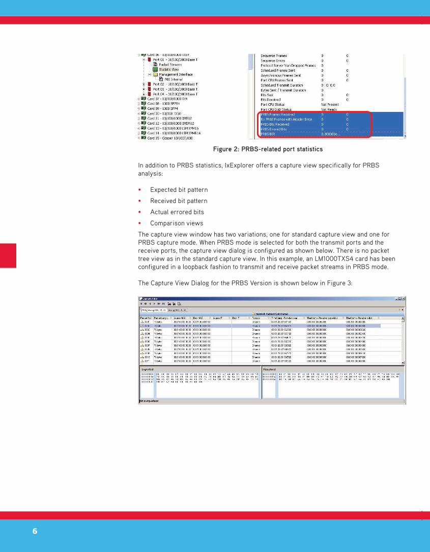
PRBS-related port statistics are shown in Figure 2 below in the blue fill-highlighted area:
• PRBS Frames Received
• Rx PRBS Frames with Header Error
• PRBS Bits Received
• PRBS Errored Bits
• PRBS Bit Error Rate (BER)
6
Figure 2: PRBS-related port statistics
In addition to PRBS statistics, IxExplorer offers a capture view specifically for PRBS analysis:
• Expected bit pattern
• Received bit pattern
• Actual errored bits
• Comparison views
The capture view window has two variations, one for standard capture view and one for PRBS capture mode. When PRBS mode is selected for both the transmit ports and the receive ports, the capture view dialog is configured as shown below. There is no packet tree view as in the standard capture view. In this example, an LM1000TXS4 card has been configured in a loopback fashion to transmit and receive packet streams in PRBS mode.
The Capture View Dialog for the PRBS Version is shown below in Figure 3:

7
Figure 3: Capture View Dialog for PRBS
In the data view (lower) panel, the expected packet configuration is displayed on the left, and the received packet on the right. This enables a bit for bit comparison. Differences are highlighted in red. Select any byte in the data view, and a bit comparison will be revealed on the bottom frame.
Figure 4: Closer look at Capture View Dialog
8
PRBS Mode Frame OperationThe PRBS mode is different for the assembly, transmission, reception, detection, and error tracking of Ixia test traffic sent and received from a device under test (DUT).
In order to put PRBS mode frame handling into context, excerpts from the Ixia Hardware and Reference Manual (version 5.30) are shown here to explain the differences in PRBS mode.
In the standard traffic packet view transmit and receive mode, where both per-port and per-flow statistics may be enabled, several operations are active:
• Auto instrumentation
• Packet group operation
• Sequence checking
• Data integrity checking
• Wide packet groups
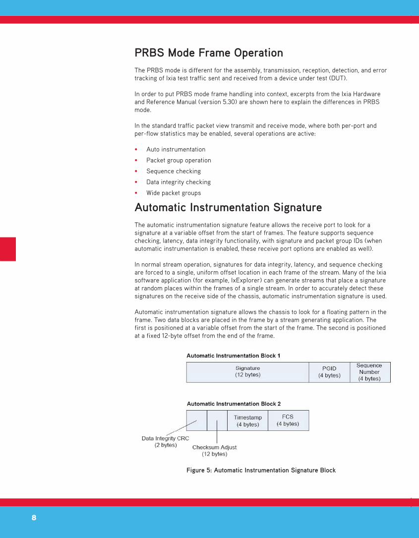
Automatic Instrumentation SignatureThe automatic instrumentation signature feature allows the receive port to look for a signature at a variable offset from the start of frames. The feature supports sequence checking, latency, data integrity functionality, with signature and packet group IDs (when automatic instrumentation is enabled, these receive port options are enabled as well).
In normal stream operation, signatures for data integrity, latency, and sequence checking are forced to a single, uniform offset location in each frame of the stream. Many of the Ixia software application (for example, IxExplorer) can generate streams that place a signature at random places within the frames of a single stream. In order to accurately detect these signatures on the receive side of the chassis, automatic instrumentation signature is used.
Automatic instrumentation signature allows the chassis to look for a floating pattern in the frame. Two data blocks are placed in the frame by a stream generating application. The first is positioned at a variable offset from the start of the frame. The second is positioned at a fixed 12-byte offset from the end of the frame.
Figure 5: Automatic Instrumentation Signature Block
9
The receive port recognizes an instrumented frame by detecting the signature in the first block. Once a signature match has occurred, the PGID and sequence number are extracted from the frame. Data integrity also starts immediately following the signature. The checksum adjust field is reserved for load modules that cannot correctly do checksums on large frames.
Packet Group OperationPacket groups are sets of packets which have matching tags, called PGIDs. Real-time latency measurements within packet groups depend on coordination between port transmission and port reception. Each transmitted packet must include an inserted 4-byte packet group signature field, which triggers the receiving port to look for the PGID. This allows the received data to be recognized and categorized into packet groups for latency analysis.
PGIDs should be used to group similar packets. For example, packet groups can be used to tag packets connected to individual router ports. Alternatively, packet groups may be used to tag frame sizes. Such groupings allow the user to measure the latency with respect to different characteristics (for example, router port number or frame size as in the above scenario).
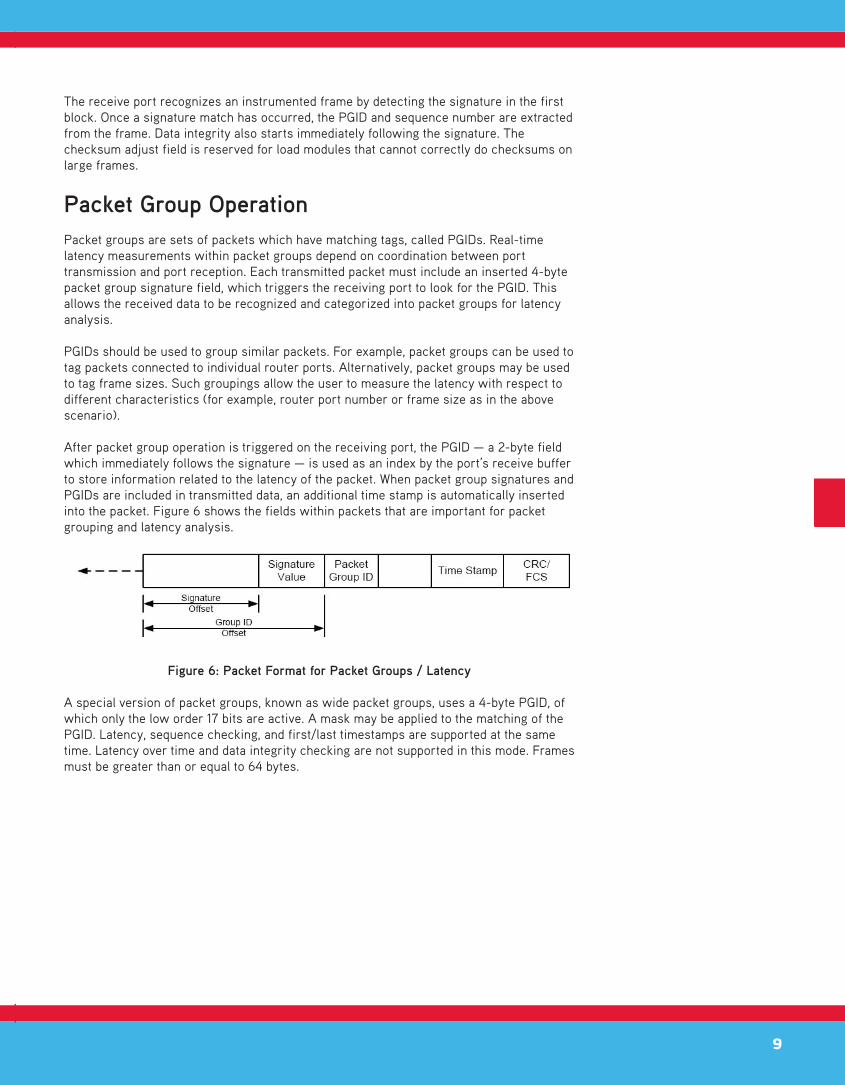
After packet group operation is triggered on the receiving port, the PGID — a 2-byte field which immediately follows the signature — is used as an index by the port’s receive buffer to store information related to the latency of the packet. When packet group signatures and PGIDs are included in transmitted data, an additional time stamp is automatically inserted into the packet. Figure 6 shows the fields within packets that are important for packet grouping and latency analysis.
Figure 6: Packet Format for Packet Groups / Latency
A special version of packet groups, known as wide packet groups, uses a 4-byte PGID, of which only the low order 17 bits are active. A mask may be applied to the matching of the PGID. Latency, sequence checking, and first/last timestamps are supported at the same time. Latency over time and data integrity checking are not supported in this mode. Frames must be greater than or equal to 64 bytes.

10
Sequence Checking OperationA number of ports have the additional ability to insert a sequence number at a user-specified position in each transmitted packet. This sequence number is different and distinct from any IP sequence number within an IP header. On the receiving port, this special sequence number is retrieved and checked, and any out-of-sequence ordering is counted as a sequence error.
As in packet groups, for sequence checking a signature value is inserted into the packet on the transmit side to signal the receive side to check the packet. In fact, this particular signature value is shared by both the packet group and the sequence checking operations. Both the signature value and sequence number are 4-byte quantities and must start on 4-byte boundaries. These fields are shown in Figure 7.
Figure 7: Packet Format for Sequence Checking
Sequence numbers are integers that start at “0” for each port when transmission is started, and increment by “1” continuously until a reset sequence index operation is performed. Note that multiple sequence errors will result when a packet is received out of sequence. For example, if five packets are transmitted in the order 1-2-3-4-5 and received in the order 1-3-2-4-5, three sequence errors will be counted:
• At 1-3, when packet 2 is missed
• At 1-3-2, when 2 is received after 3
• At 1-3-2-4, when 4 is received after 2
Data Integrity Checking OperationA number of ports also possess the ability to check the integrity of data contained in a received packet, by computing an additional 16-bit CRC checksum. As with packet groups and sequence checking, a signature value is inserted into the packet on the transmitting interface to serve as a trigger for the receiving port to notice and process the additional checksum. The data integrity operation uses a different signature value from the one shared by packet groups and sequence checking.
The data integrity signature value marks the beginning of the range of packet data over which the 16-bit data integrity checksum is calculated, as shown in Figure 8. This packet data ends just before the timestamp and normal CRC/FCS. The CRC-16 checksum value must end on a 4-byte boundary. There may be 1, 2, or 3 bytes of zeroes (padding) inserted after the CRC-16, but before the Time Stamp, to enforce all boundary conditions.
Figure 8: Packet Format for Data Integrity Checking
11
When the receive code for a port is configured to check for data integrity, received packets are matched for the data integrity signature value, and the additional CRC-16 is checked for accuracy. Any mismatches are recorded as data integrity errors.
Wide Packet GroupsThis feature allows ports that use packet groups to extend the number of bits in the PGID to 17 bits (or more).
When the receive mode is set to PRBS mode, both wide packet groups and sequence checking are automatically enabled. Latency is turned off and replaced by PRBS statistics, as described previously.
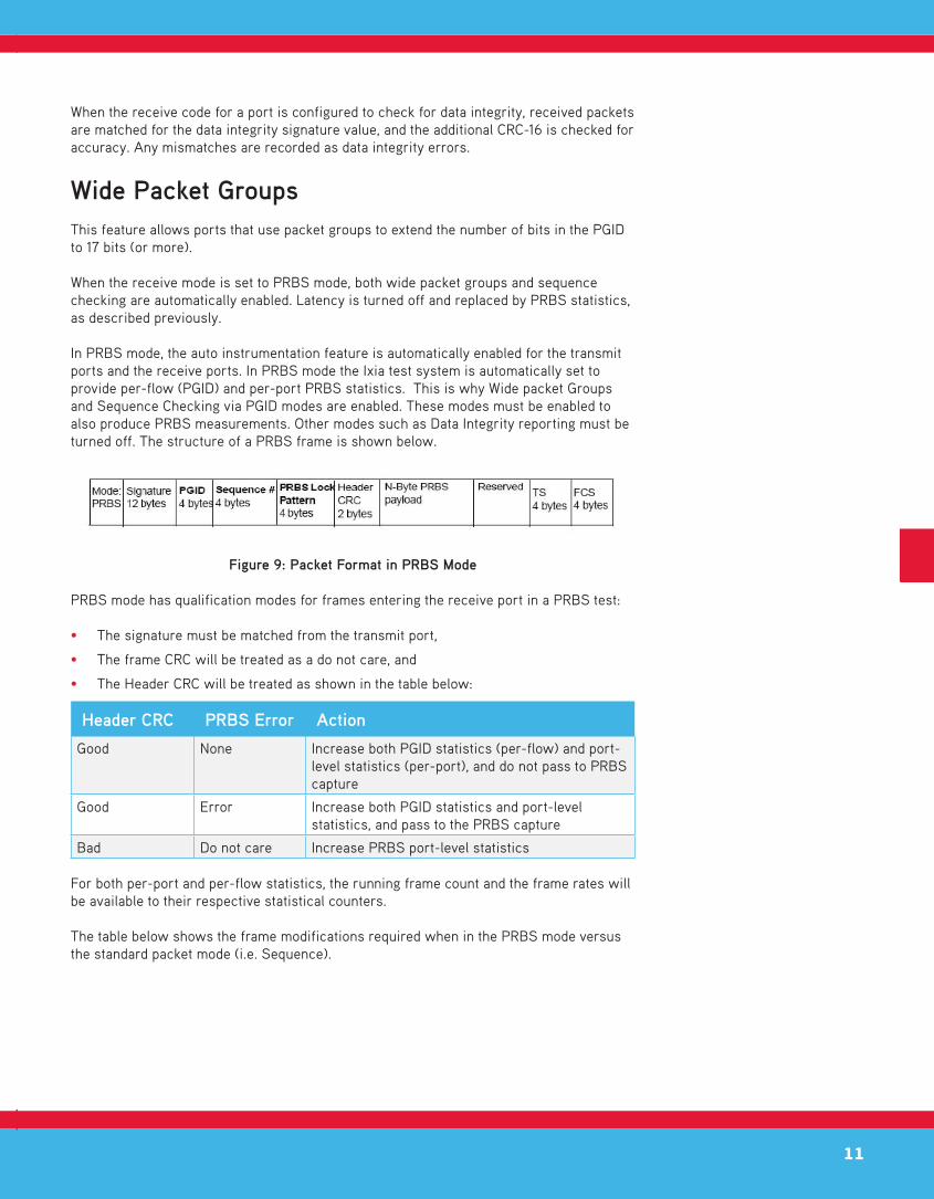
In PRBS mode, the auto instrumentation feature is automatically enabled for the transmit ports and the receive ports. In PRBS mode the Ixia test system is automatically set to provide per-flow (PGID) and per-port PRBS statistics. This is why Wide packet Groups and Sequence Checking via PGID modes are enabled. These modes must be enabled to also produce PRBS measurements. Other modes such as Data Integrity reporting must be turned off. The structure of a PRBS frame is shown below.
Figure 9: Packet Format in PRBS Mode
PRBS mode has qualification modes for frames entering the receive port in a PRBS test:
• The signature must be matched from the transmit port,
• The frame CRC will be treated as a do not care, and
• The Header CRC will be treated as shown in the table below:
Header CRC PRBS Error Action
Good None Increase both PGID statistics (per-flow) and port-level statistics (per-port), and do not pass to PRBS capture
Good Error Increase both PGID statistics and port-level statistics, and pass to the PRBS capture
Bad Do not care Increase PRBS port-level statistics
For both per-port and per-flow statistics, the running frame count and the frame rates will be available to their respective statistical counters.
The table below shows the frame modifications required when in the PRBS mode versus the standard packet mode (i.e. Sequence).

12
The frame diagram shown below is a packet with auto instrumentation (shown from the auto instrumentation block offset to the end of the packet). The region in blue highlight shows the range over which the data integrity (DI) CRC value is calculated. Note, that for PRBS mode, the DI CRC only covers the packet header and not the actual payload. The payload when in PRBS mode must be a continuous PRBS pattern up to but not including the reserved block.*
Table 1: Auto Instrumentation Packet Format
Note, that the PRBS payload pattern (shown in black double-line outline blocks) is contiguous from the PRBS Lock Pattern through the end of the “N Byte PRBS Payload.” The DI CRC is overlaid on top of the PRBS payload.
On the receive side, the PRBS checker must lock onto the PRBS Lock Pattern and then start checking from the start of the “N Byte PRBS payload” and skip the DI CRC. The DI CRC block is used to qualify the state (health) of the packet header, however, the DI CRC is not reported to the user as a data integrity check as described in the standard packet mode (i.e. sequence) when in the PRBS mode.
Ixia uses a polynomial and a seed mechanism that produces the “N Byte PRBS Payload.” The transmit ports and the receive ports both know the output of the polynomial, which is what allows a comparison of the “N Byte PRBS Payload” between the transmitted packet and the received packet. The mechanisms that manage the PRBS generation and checking are proprietary to Ixia.
All of the offsets of the various fields shown in the figure above are fixed offset; if the DUT inserts or changes the offset or content of the frame block that are in the blue region, the PRBS system will report errors. Once the “N Byte PRBS Payload” is generated, if the DUT changes or pads the N Byte PRBS content, the Ixia receive side will see that as an error and will report PRBS Errored Bits on the receive port.
*Note. The reserved block is proprietary to Ixia.
Mode 12 Bytes 4
Bytes
4 Bytes 4 Bytes 2
Bytes
N-2
Bytes
2
Bytes
2 Bytes 4
Bytes
4
Bytes
PRBS Signature PGID Sequence Number
PRBS Lock Pattern
DI CRC N Bytes PRBS Payload
Reserved Block*
Time Stamp
FCS
Sequence Checking
Signature PGID Sequence Number
N Byte Payload DI CRC Reserved Block*
Time Stamp
FCS

13

WHITE PAPER
Ixia Worldwide Headquarters26601 Agoura Rd.Calabasas, CA 91302
(Toll Free North America)1.877.367.4942
(Outside North America)+1.818.871.1800(Fax) 818.871.1805www.ixiacom.com
Ixia European HeadquartersIxia Technologies Europe LtdClarion House, Norreys DriveMaidenhead SL6 4FLUnited Kingdom
Sales +44 1628 408750(Fax) +44 1628 639916
Ixia Asia Pacifi c Headquarters21 Serangoon North Avenue 5#04-01Singapore 554864
Sales +65.6332.0125Fax +65.6332.0127
915-0120-01 Rev. A, Month 2013