an overview of low latency for wireless communications: an
TRANSCRIPT

An Overview of Low latency for WirelessCommunications: an Evolutionary Perspective
Xin Fan, Yan HuoSchool of Electronics and Information Engineering, Beijing Jiaotong University, Beijing, China
E-mail: {fanxin, yhuo}@bjtu.edu.cn
Abstract—Ultra-low latency supported by the fifth generation(5G) give impetus to the prosperity of many wireless networkapplications, such as autonomous driving, robotics, telepresence,virtual reality and so on. Ultra-low latency is not achieved in amoment, but requires long-term evolution of network structureand key enabling communication technologies. In this paper,we provide an evolutionary overview of low latency in mobilecommunication systems, including two different evolutionaryperspectives: 1) network architecture; 2) physical layer airinterface technologies. We firstly describe in detail the evolutionof communication network architecture from the second gener-ation (2G) to 5G, highlighting the key points reducing latency.Moreover, we review the evolution of key enabling technologiesin the physical layer from 2G to 5G, which is also aimed atreducing latency. We also discussed the challenges and futureresearch directions for low latency in network architecture andphysical layer.
Index Terms—Low latency, physical layer, network architec-ture, evolution.
I. INTRODUCTION
With the development of mobile communication technolo-gies, the requirements of human beings are increasing con-stantly. Once current requirements are met by communicationtechnologies, new needs will arise and then new technologieswill be expected to be updated. In this way, with the mutualpromotion of requirements and communication technologies,we have been entering the fifth generation (5G) era. 5Gis committed to creating a single platform to provide awide range of services that are classified by the Interna-tional Telecommunication Union (ITU) into three categories:enhanced mobile broadband (eMBB), massive machine-typecommunication (mMTC), ultra-reliable and low latency com-munications (URLLC) [1]. To support these services, diversesets of key performance indicators (KPIs) need to be achieved,which is a challenge for communication technologies. Amongthese KPIs, low latency that end-to-end (E2E) latency of 1 msor less is perhaps the most challenging, due to the fact thatmost latency-sensitive services need to simultaneously meetother KPIs, such as high reliability as 99.9999% [2].
As mentioned above, the requirement for low latency isbecoming more stringent step by step. The requirement forE2E latency of 1ms in 5G mobile systems is based on thefact that the fourth generation (4G) mobile communicationscan achieve 30−100 ms E2E latency [3]. The E2E latency of4G is significantly improved on the basis of several hundredmilliseconds of the third generation (3G) mobile communica-tions that also developed from the previous second generation
(2G). The current requirement for low latency cannot besatisfied by legacy mobile communication systems becauseof outdated inherent network architecture and communica-tion techniques. In order to address requirement for the lowlatency, 5G needs to make a significant further evolutionto the network architecture, while its relevant key enablingtechnologies require breakthrough innovation with respect toprevious generations. Therefore, it is extremely important totrace back the evolution of the previous and current networkarchitectures and communication technologies.
A. Related Work
In the existing literature, it can be easily found someoverviews toward 5G networks, including network architecture[4]–[6], physical layer technologies [6], [7]. Apart from this,overviews on low latency for 5G networks in Internet [8],cloud computing [9], Internet-of-Things (IoT) applications[10], and even a comprehensive survey of latency reductionsolutions in cellular networks towards 5G [2] can be alsoavailable. However, to the best of our knowledge, theseoverviews only cover 5G mobile communication systems, andthere is no clear evolutionary route on how latency has beingreduced step by step. In other words, horizontal overviews onlow latency can be found, but longitudinal ones are missing.
B. Contribution and Motivation
In this paper, we provide an overview of the latency reduc-tion for mobile communication systems from two differentevolutionary perspective. Firstly, we discuss the reduction oflatency by changing the network structure, including the radioaccess network (RAN), core network, and bearer network eachgeneration network structure changes from 2G to 5G mobilecommunication system. Further, focusing on the physicallayer, we present the communication technologies involvedin each generation of mobile communication systems forattaining low latency, including packet size, frame structure,minimum transmission interval, modulation schemes, codingschemes and so on. Last but not the least, we also point outthe major current challenges in reducing latency and possiblefuture research directions in terms of network architecture andphysical layer technologies.
Our motivation is to present a longitudinal and evolutionaryperspective on the development of low-latency schemes, witha view to seeking further space through reflecting on history.It should be noted that although we give several evolutionary
arX
iv:2
107.
0348
4v1
[cs
.NI]
7 J
ul 2
021

routes of network architecture and physical layer technologies,the detailed comparison between these solutions involved ineach evolutionary route is not within our scope of this work.
The rest of this paper is organized as follows. Section IIstates the components of latency that includes the overalllatency and physical layer latency. In the following SectionIII, we discuss the changes in network architecture from 2Gto 5G, including radio access network, bearing network andcore network. Then we present changes in the physical layertechnologies for low latency in the Section IV. Followingthat, we point out the current challenges and future researchdirections of reducing latency in the Section V. Finally, thispaper is summarized in the final Section VI. For convenience,a list of major abbreviations is presented in Table I.
II. COMPONENTS OF LATENCY
It is important to understand the generation and compositionof latency in order to better discuss the reduction of latency.In general, the cellar network latency can be divided into twoaspects: 1) control plane latency; 2) user plane latency. Thecontrol plane latency generally refers to the time required fora terminal to switch from idle state to connected state; and theuser plane latency refers to the time required for an IP message(ping packet) to be sent from a terminal to the applicationserver and then returned to the terminal. Since the users’experience of network services mainly depends on the userplane latency (the control plane latency mainly affects networkswitching), low-latency communication is more focused on theuser plane.
In terms of network architecture, the user plane la-tency consists of several components, including air inter-face, bearing network, core network and public data network(PDN)/Internet. As shown in Fig.1, the total unidirectionaltransmission latency can be expressed as:
T = TRadio + TBearing + TCore + TPDN (1)
where
• TRadio is the latency from the user terminal to the radioaccess network. This part of the latency is also known asthe air interface latency, which is mainly affected by thephysical layer transmission.
• TBearing is the latency for transmission on the bear-ing/backhaul network that bears the connection betweenthe radio access network and the core network, andbetween the core network and the PDN.
• TCore is the processing latency inside the core network.The processing includes mobility management, users’ IPaddress allocation, security management, bearer control,etc.
• TPDN is the latency of content delivery for PDN toprocess requests and establish default bearers.
Obviously, the E2E latency is approximately twice as longas the above latency, i.e., 2× T . As the main part of TRadio,
TABLE I: List of the major abbreviations
Abbreviation DefinitionRAN Radio access networkE2E End-to-endGSM Global Systems for Mobile CommunicationsGPRS General Packet Radio ServiceUMTS Universal Mobile Telecommunications SystemBTS Base transceiver stationBSC Base station controllerCs Circuit switchingPs Packet switching
RNC Radio network controllerSGW Service gatewayPGW Packet data gatewaySGSN Service GPRS supported nodeGGSN Gateway GPRS supported nodeC-RAN Centralized, Cooperative, Cloud and Clean RAN
BBU Base Band UnitRRU Remote Radio UnitNR New radioSA Standalone
NSA Non-StandaloneCU Centralized unit
AAU Active antenna unitDU Distribute unit
NFV Network function virtualizationNFV Network function virtualizationSDN Software defined networkD2D Device-to-DeviceMSC Mobile switching center
GMSC Gateway mobile switching centerMGW Media GatewayMME Mobility management entitySBA Service Based architectureNF Network function
MEC Mobile edge computingPDH Plesiochronous digital hierarchySDH Synchronous digital hierarchy
MSTP Multi-service transmission platformPTN Packet transport networkOTN Optical transport networkPON Passive optical networkNP ProcessorTM Traffic managerTTI Transmission time interval
TDMA Time division multiple accessRLC Radio Link Control
EDGE Enhanced data rate for GSM evolutionCDMA Code division multiple access
LTE Long Term EvolutionCP Cyclic prefix
HSDPA High speed downlink packet accessOFDM Orthogonal frequency division multiplexing3GPP The 3rd Generation Partnership ProjectLDPC Low-density parity checkIDMA Interleave division multiple accessSCMA Sparse code multiple accessNOMA Non orthogonal multiple accessFBMC filter bank multi-carrierUFMC Universal filtered multi-carrierGFDM Generalized frequency division multiplexingAUSF Authentication Server FunctionAMF Core Access and Mobility Management FunctionSMF Session Management FunctionUPF User plane FunctionNEF Network Exposure FunctionNRF NF Repository FunctionPCF Policy Control function
UDM Unified Data ManagementAF Application Function
NSSF Network Slice Selection Function

the physical layer transmission latency can be divided into fivedistinct components as follows:
TPL = Tque + Tttt + Tproc + Tprop + Tretr (2)
where• Tque is the queuing latency that is the time needed for
the current packet to wait for the completion of thetransmission of the previous packet. The queuing latencyof a particular packet depends on the number of packetsarriving in advance and waiting for transmission to thelink. If the queue is empty and no other data packets arecurrently being transmitted, the queuing latency of thedata packet is 0.
• Tttt is the time-to-transmission latency that is the timerequired to push all the bits of a data packet to the link(from the first bit of the transmitted data packet to thelast bit of the packet).
• Tproc is the processing latency including encoding anddecoding, modulation and demodulation, channel inter-leaving, channel estimation, rate matching, layer mapper,scrambling, data and control multiplexing, etc. Thesedepend not only on physical layer technologies, but alsoon the processing capacity of user terminals and basestations.
• Tprop is the propagation latency that is the time it takesfor electromagnetic wave to propagate a certain distancein the channel.
• Tretr is the latency of retransmission. Low link reliabilitycan easily result in packet loss, which involves retrans-mitting.
E2E latency is the sum of latency on multi-segment paths.It can not satisfy the extreme latency requirement of 1 ms onlyby optimizing a local latency. Therefore, the implementationof 5G ultra-low latency requires a series of organically com-bined technologies. On the one hand, evolutionary changesin network architecture are needed to flatten the networkstructure and sink content providers. On the other hand, it isnecessary for air interface be reconstructed to greatly reducethe transmission latency of physical layer. The vision ofreducing latency can not be achieved overnight, but requireslong-term efforts.
In the following two sections, we will discuss how to reducelatency from two aspects of the network architecture andphysical layer air interface technologies in an evolutionaryperspective, respectively.
III. EVOLUTIONARY NETWORK ARCHITECTURE FOR LOWLATENCY
Mobile communication networks have different architec-tures in different periods. Every generation of network archi-tecture change is an innovation or evolution, which may bevery wide-ranging for different requirements. This paper onlyhighlights the significant changes in reducing latency, whichmay not necessarily provide a comprehensive overview ofchanges in network architecture. In this section, we provide an
evolution of network architecture from 2G to 5G 1, includingthree parts: radio access network, core network and bearingnetwork, as shown in Fig. 1.
A. Radio Access Network
In fact, the earliest 2G network is known as Global Systemsfor Mobile Communications (GSM) networks, which also doesnot support data transmission, but only used digital signals toprovide telephone services. From GSM network to GeneralPacket Radio Service (GPRS) networks (called as 2.5G),packet switching service was introduced, and then began toprovide data service. Therefore, it should be noted that theevolution of network architecture in terms of latency reductionstarts at 2.5G.
1) 2G Radio Access Network: The radio access network in2G networks is composed of Base Transceiver Station (BTS)and Base Station Controller (BSC). BTS receives the wirelesssignal from mobile station (MS) through the Um air interface,then transmits it to BSC through the Abis interface. BSC isresponsible for the management and configuration of wirelessresources (such as power control, channel allocation, etc.), andthen transmits the received signal to the core network throughthe A interface.
2) 2G-2.5G Radio Access Network Evolution: The originalGSM network is based on circuit switching technology anddoes not have the function of supporting packet switchingservices. Therefore, in order to support packet services, severalfunctional entities have been added to the original GSM net-work structure, which is equivalent to adding a small networkon the basis of the original network to form a GPRS network.For the radio access network, Packet Control Unit (PCU)is added to the BSC to provide packet switching channel.Starting from the GPRS network structure, two concepts areintroduced, as follows.
• Circuit switching (Cs) domain: based on circuit switch-ing, mainly including voice services, also includingcircuit-based data services, the most common is the faxservice;
• Packet switching (Ps) domain: based on packet switching,mainly for common data services, including streamingmedia services, voice over IP (VOIP) and so on.
3) 2.5G-3G Radio Access Network Evolution: The 3Gmobile cellular system has several standard, among whichthe Universal Mobile Telecommunications System (UMTS)is currently the most widely used. UMTS, sometimes alsoreferred to as 3GSM, emphasizes the integration of 3G tech-nologies and is a successor to the GSM standard. And packetswitching system in UMTS is evolved from GPRS system, sothe architecture of the system is quite similar but not exactlythe same.
Instead of BTS and BSC, the composition of the radioaccess network is replaced by NodeB and Radio Network
1The first generation mobile communication (1G) only provides voiceservice with analog signals, but no data transmission. Therefore, this paperignores the discussion of 1G network architecture.

NSSF NEF NRF PCF UDM AF
AUSF AMF SMF
UPF
AAU
DU
CU
RRU
BBU Bool
Control Plane
User Plane
User And Control Plane
2G GSM
2G GPRS
3G
4G
5G
Radio Access Networks Core Networks External Networks
UE
UE
UE
UE
UE
BTS
BTS
BSC
NodeB
eNodeB
gNB
RNC
MSC GMSC
MSC Server
MGW
GGSNSGSN
IP Networks
(Internet)
PSTN
Abis
A
Gb
Iub
Iur
Iu-Ps
Iu-Cs
MME
S-GW
Um
Um
Uu
LTE-Uu
NR-Uu
X2
S1-MME
S1-U
Gn
SGi
Gi
Gn
P-GW
S5
S4
SGs
S11
S3
Ai
34
Mc
E
N6
N3
N4
N2
NsmfNamfNausf
Nnssf Nnef Nnrf Npcf Npcf Naf
Universal
ServerXn
Fig. 1: The network architecture from 2G to 5G
Controller (RNC). The functions of BTS and NodeB arebasically the same, but there are still some differences betweenthem. The differences are instrumental in reducing the latencyas follows:
• The interface between BTS and BSC is Abis, while theinterface between NodeB and RNC is Iub. In physicallayer transmission, Abis is a private interface that sup-ports either ATM (E1/T1) or IP, while Iub is a open in-terface that supports ATM, IP, and Hybrid (ATM and IP).Because these interfaces are logical, many interfaces canbe multiplexed and merged into a single transmission line.This reduces the number of interfaces and facilitates theswitching efficiency between lines, which is conducive tothe reduction of latency.
• In GSM, the overwhelming majority of control functionsare implemented by BSC. BTS only plays the functionof completing the coding and transmission of physicallayer according to the instructions of RNC, and BTS itselfbasically has no ability to control and schedule physicalresources. However, in order to achieve greater through-put capability on the air interface, the functions of NodeB
are enhanced. The concepts of physical layer retrans-mission, spreading/despreading, fast resource schedulingand the closed (inner) loop power control, are introducedat the NodeB level. By introducing these functions onNodeB closer to the air interface, which should be onlyavailable with RNC, the efficiency of retransmission andair resource scheduling is accelerated. As a result, bysinking several control functions from RNC to NodeB,lower latency is achieved.
In addition to the changes in NodeB, there are also improve-ments between RNC and BSC that are beneficial to reducingthe latency, as follows
• The PCU entity was removed and its functions wereincorporated into RNC, which helps to reduce latency.
• The interfaces between the radio access network and thecore network are A interface in GSM and Gb interfacein GPRS, respectively, whereas the two interfaces areconsolidated into the Iu interface in UMTS. The Iu inter-face connecting the RNC to circuit-switched core networkis known as Iu-CS and the Iu interface connecting theRNC to packet-switched core network is known as Iu-
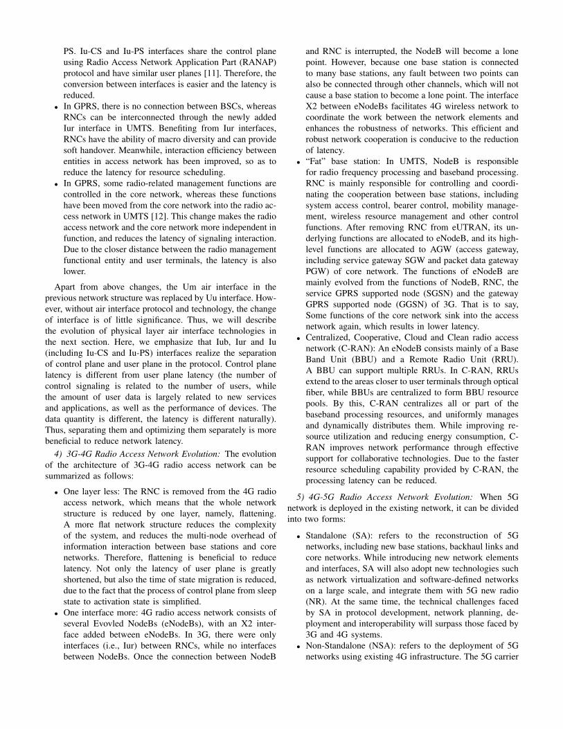
PS. Iu-CS and Iu-PS interfaces share the control planeusing Radio Access Network Application Part (RANAP)protocol and have similar user planes [11]. Therefore, theconversion between interfaces is easier and the latency isreduced.
• In GPRS, there is no connection between BSCs, whereasRNCs can be interconnected through the newly addedIur interface in UMTS. Benefiting from Iur interfaces,RNCs have the ability of macro diversity and can providesoft handover. Meanwhile, interaction efficiency betweenentities in access network has been improved, so as toreduce the latency for resource scheduling.
• In GPRS, some radio-related management functions arecontrolled in the core network, whereas these functionshave been moved from the core network into the radio ac-cess network in UMTS [12]. This change makes the radioaccess network and the core network more independent infunction, and reduces the latency of signaling interaction.Due to the closer distance between the radio managementfunctional entity and user terminals, the latency is alsolower.
Apart from above changes, the Um air interface in theprevious network structure was replaced by Uu interface. How-ever, without air interface protocol and technology, the changeof interface is of little significance. Thus, we will describethe evolution of physical layer air interface technologies inthe next section. Here, we emphasize that Iub, Iur and Iu(including Iu-CS and Iu-PS) interfaces realize the separationof control plane and user plane in the protocol. Control planelatency is different from user plane latency (the number ofcontrol signaling is related to the number of users, whilethe amount of user data is largely related to new servicesand applications, as well as the performance of devices. Thedata quantity is different, the latency is different naturally).Thus, separating them and optimizing them separately is morebeneficial to reduce network latency.
4) 3G-4G Radio Access Network Evolution: The evolutionof the architecture of 3G-4G radio access network can besummarized as follows:
• One layer less: The RNC is removed from the 4G radioaccess network, which means that the whole networkstructure is reduced by one layer, namely, flattening.A more flat network structure reduces the complexityof the system, and reduces the multi-node overhead ofinformation interaction between base stations and corenetworks. Therefore, flattening is beneficial to reducelatency. Not only the latency of user plane is greatlyshortened, but also the time of state migration is reduced,due to the fact that the process of control plane from sleepstate to activation state is simplified.
• One interface more: 4G radio access network consists ofseveral Evovled NodeBs (eNodeBs), with an X2 inter-face added between eNodeBs. In 3G, there were onlyinterfaces (i.e., Iur) between RNCs, while no interfacesbetween NodeBs. Once the connection between NodeB
and RNC is interrupted, the NodeB will become a lonepoint. However, because one base station is connectedto many base stations, any fault between two points canalso be connected through other channels, which will notcause a base station to become a lone point. The interfaceX2 between eNodeBs facilitates 4G wireless network tocoordinate the work between the network elements andenhances the robustness of networks. This efficient androbust network cooperation is conducive to the reductionof latency.
• “Fat” base station: In UMTS, NodeB is responsiblefor radio frequency processing and baseband processing.RNC is mainly responsible for controlling and coordi-nating the cooperation between base stations, includingsystem access control, bearer control, mobility manage-ment, wireless resource management and other controlfunctions. After removing RNC from eUTRAN, its un-derlying functions are allocated to eNodeB, and its high-level functions are allocated to AGW (access gateway,including service gateway SGW and packet data gatewayPGW) of core network. The functions of eNodeB aremainly evolved from the functions of NodeB, RNC, theservice GPRS supported node (SGSN) and the gatewayGPRS supported node (GGSN) of 3G. That is to say,Some functions of the core network sink into the accessnetwork again, which results in lower latency.
• Centralized, Cooperative, Cloud and Clean radio accessnetwork (C-RAN): An eNodeB consists mainly of a BaseBand Unit (BBU) and a Remote Radio Unit (RRU).A BBU can support multiple RRUs. In C-RAN, RRUsextend to the areas closer to user terminals through opticalfiber, while BBUs are centralized to form BBU resourcepools. By this, C-RAN centralizes all or part of thebaseband processing resources, and uniformly managesand dynamically distributes them. While improving re-source utilization and reducing energy consumption, C-RAN improves network performance through effectivesupport for collaborative technologies. Due to the fasterresource scheduling capability provided by C-RAN, theprocessing latency can be reduced.
5) 4G-5G Radio Access Network Evolution: When 5Gnetwork is deployed in the existing network, it can be dividedinto two forms:
• Standalone (SA): refers to the reconstruction of 5Gnetworks, including new base stations, backhaul links andcore networks. While introducing new network elementsand interfaces, SA will also adopt new technologies suchas network virtualization and software-defined networkson a large scale, and integrate them with 5G new radio(NR). At the same time, the technical challenges facedby SA in protocol development, network planning, de-ployment and interoperability will surpass those faced by3G and 4G systems.
• Non-Standalone (NSA): refers to the deployment of 5Gnetworks using existing 4G infrastructure. The 5G carrier

based on NSA architecture only carries user data, and itscontrol signal is still transmitted through the 4G network.
In this paper, we only consider the case of SA. In 5Gnetwork, C-RAN still maintains the characteristics of the four“C” but also has some significant evolution for low latency.
Firstly, because the demands in 5G is diversified, the net-work needs to be diversified; because the network needs to bediversified, it needs to be sliced; because it needs to be sliced,the network elements need to be able to move flexibly; becausethe network elements need to move flexibly, the connectionsbetween the network elements also needs to be flexible. Asa result, 5G radio access network is redefined as NG-RAN,in which the base station is no longer eNodeB but gNB. ThegNB reconstructs BBUs and RRUs into the following threefunctional entities:
• Centralized Unit (CU): The non-real-time part of theoriginal BBU will be separated and redefined as CU,which is responsible for handling non-real-time protocolsand services.
• Active Antenna Unit (AAU): Part of the physical layerprocessing functions of original BBU is combined withthe original RRU and passive antenna to form AAU.
• Distribute Unit (DU): The remaining functions of theoriginal BBU are redefined as DU, which handles phys-ical layer protocols and real-time services.
According to different service requirements and perfor-mance indicators, the network is divided into logical combi-nations of network functional entities, and the sliced networkis used to provide specified services for target users andterminals. The reconstructed three functional entities coincidewith the implementation of slicing. According to the 5Gstandard, CU, DU and AAU can be separated or co-located,so there will be a variety of network deployment patterns.In low-latency scenarios, DU needs to be deployed close touser terminals. The deployment of units that handle real-timeservices independently close to user terminals can greatlyreduce latency.
Secondly, Network Function Virtualization (NFV) and Soft-ware Defined Network (SDN) are introduced into 5G net-works. On the one hand, with the introduction of NFV, 5Gnetwork is constructed into a virtualized network environment.After virtualization, differentiated software functions run onthe same hardware devices, and different network functionswill share hardware computing, storage and communicationresources. On the other hand, the introduction of SDN im-proves the network’s programmability and separates the dataand control aspects of the network. Under the NFV/SDNnetwork architecture, resource pools that are inherited from 4Gcan be evolved into virtualized cloud resource pools (VCRPs).Resource allocation in VCPR can maximize the reuse ofnetwork resources, and bring more flexible and rapid sharingcapability. NFV/SDN packages a series of network functionsinto a single action to minimize network sessions, whichmeans a reduction in latency.
Thirdly, compared with cloud computing nodes, fog com-
puting nodes are closer to user terminals. Therefore, introduc-ing fog computing into wireless access network to build fogRAN (F-RAN) can alleviate the pressure of forward/backhaullinks by virtue of the computing and caching potential ofusers and edge devices. In such a F-RAN network architecture,the distributed computing and caching capabilities of networkedges can be effectively integrated through collaboration,which enhances the local real-time processing, transmissionand control capabilities. By carrying sinking network func-tions and edge applications, local information processing andservice distribution can be realized, providing lower the E2Elatency performance.
Last but not the least, Device-to-Device (D2D) communi-cation is not a new technology proposed by 5G, but D2D isdestined to develop in 5G. Network participants share partof their hardware resources, including information processing,storage and network connectivity. These shared resources pro-vide services and resources to the network and can be accesseddirectly by other users without passing through intermediaryentities. This kind of direct communication mode will greatlyreduce the communication E2E latency.
B. Core Network
The core network is the “management center”, which ismainly responsible for managing data, sorting data, and thendistributing data. The functions implemented by each gen-eration of core network are slightly different, which alsocorresponds to the changes of architecture. We enumerate thestructural changes for latency reduction, mainly involving thesinking of functions and the separation of control and userplane.
1) 2G-2.5G Core Network: In GSM, the core network ismainly composed of Mobile Switching Center (MSC), VisitLocation Register (VLR), Home Location Register (HLR), Au-thentication Center (AUC), Equipment Identity Register (EIR)and other functional entities. MSC is the core, responsible fordealing with the specific service of users. VLR and HLR aremainly responsible for mobility management and user databasemanagement functions. AUC and EIR are responsible forsecurity functions. In addition, the Gateway Mobile SwitchingCenter (GMSC) is responsible for providing access to externalnetwork interfaces.
In the core network of GPRS, SGSN and GGSN are added,whose functions are consistent with MSC and GMSC, exceptthat they deal with packet services and external network accessto IP network, respectively.
2) 2.5G-3G Core Network: The most significant change of3G core network is the introduction of softswitch to separatethe call control function from the media gateway (transportlayer) in CS domain. The basic call control function isimplemented by software, which realizes the separation of calltransmission and call control, and establishes a separate planefor control, switching and software programmable functions.Specifically, the bearer and control functions of the MSCare separated and divided into two nodes, MSC-server andMedia Gateway (MGW). Call control, mobility management,

and media control functions are performed on the MSC-server,while the service bearer and media conversion functions arecompleted on the MGW. The biggest change brought by thestructure of the separation of bearer and control is that MSC-servers and MGWs can be deployed separately. MSC-serversare usually concentrated in provincial capitals or regionalcenters. The centralized management of MSC-servers canimprove the efficiency of operation and maintenance, whilethe MGW can be set according to the best service point.This centralized management and distributed service deliverynetwork architecture is conducive to providing better services(including low latency).
Compared with CS domain, the PS domain only separatesthe user plane from the control plane logically, but notphysically. The 3G core network in PS domain does not haveseparate entities to implement control plane and user plane,respectively 2.
3) 3G-4G Core Network: The evolution of 4G core networkhas two main aspects as follows:
• The CS domain is removed and the network architectureof a single PS domain is implemented. This single net-work architecture reduces signaling interaction and thusreduces latency.
• The control plane and the user plane are completelyseparated, physically and logically. The functions ofcontrol plane and user plane are assumed by differentnetwork entities respectively. The control plane elementis Mobility Management Entity (MME), which is mainlyused for user access control and mobility management.The user plane network element is the System Architec-ture Evolution-Gateway (SAE-GW), including Service-Gateway (S-GW) and Packet Data Network-Gateway (P-GW), is mainly used to bear data services. The processingefficiency of the core network is improved, so the latencyis reduced.
4) 4G-5G Core Network: With the complexity and diversityof services in 5G era, the integrated network element structureof 4G core network can not flexibly cope with the changingservice applications. In order to make the network elementsmore flexible and better respond to diversified applications,the 5G core network is evolving to a discrete Service Basedarchitecture (SBA), which has two characteristics:
• Firstly, the separation of network functions absorbs theoriginal design idea of NFV cloud, hoping to build thenetwork in a way of software-based, modularized andservice-oriented.
• Secondly, the user-side functions are free from the “cen-tralization” constraints, so that they can not only beflexibly deployed in the core network, but also can bedeployed in the radio access network.
2Direct tunnel technology is an innovative technology in 3G [13], [14],which this paper does not focus on because of its uniqueness. The direct tunneltechnology refers to the establishment of a “direct channel” from RNC toGGSN. User plane data is transmitted in the “direct channel” without passingthrough SGSN to realize the flattening of network plane.
Both of the above characteristics are beneficial to the reduc-tion of latency. In order to achieve these two characteristics,the 5G core network has the following two evolutions from4G:
• Traditional network entities are split into multiple net-work functions (NFs) modules. In line with the conceptof SBA, each NF is independently autonomous, andindividual changes do not affect other NFs. The functionsof the 4G core network elements can be found in the NFsof the 5G core network, but the architecture has changedfrom monolithic to micro-service. The most obviousexternal manifestation of this change is the substantialincrease in network elements. These elements seem a lot,in fact, the hardware is virtualized in the virtualizationplatform. The purpose of this change is to make thenetwork more flexible, open and scalable, so as to realizenetwork slicing and provide better services.
• The traditional point-to-point communication betweennetwork elements is abandoned. The interface of eachNF is a service interface. Each NF provides servicesthrough its own service-oriented interface, and allowsother authorized NFs to access or invoke their ownservices. Because the underlying transport protocols arethe same, all service interfaces can be transmitted onthe same bus, that is, bus communication mode. Thisbus communication mode can provide higher informationtransmission efficiency and lower latency.
As the network elements are subdivided, the network el-ements on the user plane can further sink to mobile edgecomputing (MEC) nodes. The MEC technology enables appli-cations, services and content to be deployed locally, near-byand distributed by migrating computing storage and servicecapabilities of the core network to the edge of the network.Benefiting from this, the content of service caching is closeto the user terminal device, thus greatly reducing the serviceconnection and response latency 3.
C. Bearer Network
Bearer networks, sometimes referred to as transport net-works or backhaul networks, are responsible for bearingand transmitting information. Generally speaking, the bearernetwork is the connecting part between the access network andthe core network. In fact, the connections between the internalnodes of the radio access network and the core network shouldalso be included. Although the bearer network is not the maintarget of low latency improvement, it also has to undertakesome improvements in low latency. The latency of bearer net-work comes from two parts: 1) the time of signal propagationin medium; 2) the forwarding latency of transmission devices.
3After introducing MEC technology, by superimposing MEC servers on thebase station side, content extraction and caching can be accomplished directlyby MEC servers. In this way, when other terminals within the same basestation call the same content, they can obtain directly from MEC servers. Nomore duplicate acquisition through the core network, which effectively savesthe system resources on the core network side. At the same time, due to thesinking of service content, the corresponding service response latency will besignificantly shortened.

We list some macro-evolutionary measures for lower latencyas follows.
1) Transmission distance: As mentioned above, the func-tions of core networks are sinking from 2G to 5G networks.What’s more, the application of MEC enables some low-latency services to be implemented directly in MEC deviceswithout going through the core network. In this way, thetransmission distance of the bearer network will be reduced,which means the transmission latency will be reduced. Inaddition, the flattening of the network architecture reducesthe number of entities and forwarding hops, thus reducing theforwarding latency.
2) Transmission media: In the early stage of communi-cation development, T1/E1 copper lines (circuit switching)was used in bearer networks. With the rapid increase ofmobile devices, the development of 3G technologies havebrought tremendous operational expenditure (OPEX) pressureto bearer networks. Due to its low price and some other advan-tages (larger transmission bandwidth, larger channel capacity,lower line loss, longer transmission distance, stronger anti-interference ability, etc.), optical fiber transmission has beenwidely used. In the 4G network, removing the CS domainto promote “All-IP”, optical fiber has become the main forceof bearer networks. However, there are still some electricalnodes in 4G networks, which cause some performance (in-cluding latency) losses due to the photoelectric conversionbetween optical nodes and electrical nodes. Thus, 5G putsforward the concept of all-optical network (referring to theelectrical/optical and optical/electrical conversion of signalonly when it comes in and out of the network) to improvenetwork performance.
On the other hand, with the rise of millimeter wave andlarge-scale Multiple-Input Multiple-Output (MIMO) technolo-gies, microwave has become a new solution for bearer net-works. Generally, microwave transmission has lower latencyand lower OPEX than optical transmission [2].
3) Transmission technologies: The transmission technolo-gies of bearer networks have experienced the evolution ofplesiochronous digital hierarchy (PDH), synchronous digitalhierarchy (SDH), multi-service transmission platform (MSTP),packet transport network (PTN), optical transport network(OTN) and passive optical network (PON). The main purposeof these technological evolution is not to lower latency (itpay more attention to capacity, bandwidth and cost), butit still have some impact on latency. The impact of thesetransmission technologies on latency in the evolution processcan be summarized as follows:
• From PDH to SDH, the rate standard is standardized,the interface is unified, and the management capability isenhanced.
• From SDH to MSTP, the ip-based interfaces (IP overSDH) are implemented to enhance the capacity of multi-service bearing and scheduling.
• From MSTP to PTN, by adopting multi-protocol label
switching (MPLS) 4, the processing delay of forwardingbetween devices is reduced.
• From PTN to OTN, integrating SDH and wavelengthdivision multiplexing (WDM) technologies, OTN realizesoptical crossover instead of fiber hopping to provide moreflexible scheduling while providing large capacity forlong-distance transmission. By enhancing packet process-ing and routing forwarding capabilities, OTN can meetthe needs of 5G bearer network, such as large bandwidth,low latency, high reliability, network slicing and so on.
• From OTN to PON, PON replaces electrical devices withoptical devices in order to realize all-optical network,and thus reduces the latency of electrical/optical andoptical/electrical conversion between devices.
In addition to the above mainstream technologies, 5G hasalso emerged new bearer network technologies to reducelatency as follows:
• Cut-through switching: The traditional data forwardingmethod is that the port checks and forwards after obtain-ing a complete data packet, which will introduce partiallatency. Cut-through switching is the fastest forwardingmode for a switch. After receiving the destination MACaddress of a data frame, the switch immediately forwardsdata to the destination port. Subsequent data is forwardedone byte at a time, which greatly reduces the serialforwarding latency.
• Flexible ethernet (FlexE): FlexE achieves physical iso-lation between sub-MACs and guarantees low-latencyservice bandwidth. At the same time, the low-latencyidentifications of FlexE can be passed to network pro-cessor (NP), traffic manager (TM) so as to achieve E2Elow-latency channel.
• Latency-aware priority: Optimizing NP kernel to sensethe priority of low-latency services, a dedicated channelfor low-latency services can be opened up.
• Priority-based latency scheduling: According to the pri-ority of the delay traffic from NP, TM adopts message-through scheduling and preemptive scheduling mecha-nism to guarantee the requirement of low-latency ser-vices.
IV. EVOLUTIONARY PHYSICAL LAYER SOLUTIONS FORLOW LATENCY
In order to achieve low latency, it is not only necessaryto change the network architecture, but also the wireless airinterface technologies. In this section, we mainly focus on theevolution of physical layer technologies to reduce TPL, includ-ing frame structure, scheduling, multiple access, modulation,channel coding and signal carrier. The main evolutionaryphysical layer solutions for low latency are summarized inTable II.
4MPLS establishes a label forwarding channel (label switching path, LSP)for messages through pre-assigned labels. At each device in the channel, onlyquick label switching is required (one lookup), thus saving processing time.

TABLE II: Summary of evolutionary physical layer technologies for low latency.
Framestructure Scheduling
schemesChannelcoding
Multipleaccess Modulation Typical
frequency bandsFrame length The minimum
scheduling unit TTI
2G GPRS A TDMAframe:60 ms
A RLC block 20 ms NAN Convolutionalcode
TDMA;FDMA
GMSK;QPSK
Uplink (UL):890-915 MHz;
E-EDGE 10 ms Downlink (DL):935-960 MHz
3G
WCDMA
A superframe:720 ms;A radio frame:10 ms;A short frame:2 ms
R99:a radio frame;HSDPA:a short frame
R99:10 ms;HSDPA:2 ms
Transferringsome radiointerfacecontrolfunctionsfrom RNCto basestation
UL:1940-1955 MHz;DL:2130-2145 MHz
TD-SCDMA
A superframe:720 ms;A radio frame:10 ms;A subframe:5 ms
A subframe 5 ms Turbocode CDMA
GMSK;QPSK;16 QAM
UL:1880-1900 MHz;DL:2010-2025 MHz
CDMA2000
A superframe:720 ms;A radio frame:10 ms;A slot:1.67 ms;
A slot 1.67 ms
UL:1920-1935 MHz;DL:2110-2125 MHz
4G
A radio frame:10 ms;A subframe:1 ms4f = 15kHz
A subframe 1 msPre-scheduling;Semi-staticscheduling
OFDM
GMSK;QPSK;16 QAM;64 QAM
UL:2500-2570 MHz;DL:2620-2690 MHz
5G
A radio frame:10 ms;A subframe:1 ms;The specificintra-framestructureis shown inthe Table III.
An OFDMsymbol
(including CP)
SeeTable III
Allocationby group;Prioritypreemptionscheduling
Data:LDPC;Control:Polar
NOMA;IDMA;SCMA;FBMC;UFMC;GFDM
GMSK;QPSK;16 QAM;64 QAM;256 QAM
FR1:0.45-6 GHz;FR2:24.25-52.6 GHz
A. Frame Structure
In GPRS, the structure of 26-multiframe and 52-multiframefor CS in GSM is replaced by a new 52 time division multipleaccess (TDMA) frame structure in PS domain. This new framestructure transmits data in Radio Link Control (RLC) blockmode. One RLC block contains 4 TDMA frame, and oneTDMA frame contains eight time slots. All the 52 TDMAframes constitute 12 RLC blocks and 4 idle blocks. Since theduration of each slot is 0.577 milliseconds, the duration of all52 TDMA frames is 52 ∗ 0.577 ∗ 8 = 240ms. Therefore, eachRLC block period is 240
12 = 20ms. This RLC block period isreferred to as the transmission time interval (TTI) in UMTS.
TTI represents the minimum data transmission time, refer-ring to the length of an independent decoded transmission ina wireless link, and is the basic unit of resource schedulingand management. Reducing TTI is equivalent to reducingTttt, Tproc and Tprop. At the same time, a shorter TTI canincrease the number of physical layer retransmissions in agiven time, thus ensuring link efficiency, i.e. reducing Tretr.TTI is the main source of data exchange latency, so most ofthe evolutionary schemes for reducing the latency in physicallayer begin with reducing TTI.
TABLE III: The supported transmission numerologies in 5G.
Parameter / Numerology (n) 0 1 2 3 44f (KHz) 15 30 60 120 240A slot (µs) 1000 500 250 125 62.5
The number of OFDMsymbols per slot
(Normal CP)14 14 14 14 14
The effective length ofan OFDM symbol (µs) 66.67 33.33 16.67 8.33 4.17
Length of a CP (µs) 4.69 2.34 1.17 0.57 0.29TTI (µs): The length of
an OFDM symbol(including CP)
71.35 35.68 17.84 8.92 4.46
Enhanced data rate for GSM evolution (EDGE) is a directevolution of GPRS, often referred to as 2.75G 5. In the evolu-tionary version of EDEG (called as E-EDGE), the originalRLC block with 4 consecutive TDMA frames on a singlechannel is changed to 2 consecutive TDMA frames on a dualchannel. As a result, the TTI is reduced from 20 ms to 10 ms.
There are many formats for 3G networks, the main-stream of which are wideband code division multiple access
5Since EDGE uses the same architecture of GPRS, we did not introduce itin the evolution of network architecture.

(WCDMA), time division - synchronous code division multi-ple access (TD-SCDMA), and code division multiple access2000 (CDMA2000). The frame structure of WCDMA andTD-SCDMA is composed of superframe and radio frame. Asuperframe consists of 72 radio frames. Each radio framelasts for 10 ms. In the 3rd Generation Partnership Project(3GPP) Release99 version of WCDMA, the minimum unit ofresource scheduling is frame length, i.e., TTI is 10ms. And inthe 3GPP Release5 version, the high speed downlink packetaccess (HSDPA) is applied to WCDMA, which introduces ashort frame structure. The duration of each short frame is 2ms, which is the minimum unit of resource scheduling, thatis, TTI is reduced to 2 ms. TD-SCDMA introduces subframesas resource scheduling units, each of which has a length of5 ms, i.e., TTI is 5 ms. In CDMA 2000, the radio frame iscomposed of 16 slots. The slot length of 1.67ms is the basicunit of resource scheduling, so TTI is 1.67ms. In summary,the minimum TTI that 3G can achieve is 1.67 ms.
In Long Term Evolution (LTE) systems, the radio framestructure is also adopted. The radio frame length is 10 msand consists of two half-frames with a length of 5ms. Eachhalf-frame consists of five sub-frames with a length of 1 ms,including four ordinary sub-frames and one special sub-frame.Therefore, the whole frame can also be understood to bedivided into 10 sub-frames with length of 1ms as the unitof data scheduling and transmission (i.e., TTI).
Following previous generations of mobile communications,5G should adopt a shorter sub-frame structure. But unlikemany people’s expectations, 5G still adopts the same 1mssub-frame as 4G LTE . This is mainly due to the long-termexistence of LTE, so 5G needs to consider the compatibilityof new radio (NR) and LTE. In order to achieve low latency,the compromise is that the number of orthogonal frequencydivision multiplexing (OFDM) symbols in a sub-frame is nolonger always 14. In 5G NR, resources are scheduled in unitsof OFDM symbols instead of sub-frames. That is, the lengthof TTI depends on the length and number of OFDM symbols.5G NR support multiple numerologies (including subcarrierspacing and symbol length) for different services. There isonly one slot fixed in each subframe in LTE, whereas thenumber of slots contained in NR subframe is related to thespecific numerology. LTE uses a fixed subcarrier spacing of15KHz, while the subcarrier spacing in NR is 4f = 15 ∗ 2nKHz, n ∈ {0, 1, 2, 3, 4}. The OFDM symbol duration is
115∗2nms, n ∈ {0, 1, 2, 3, 4}. Therefore, TTI consists of mOFDM symbol duration and the duration of cyclic prefix (CP).The specific parameter sets (i.e., numerologies) are shown inthe Table III.
In addition, 5G NR uses a more efficient mechanism toachieve low latency, that is, the so-called “mini-slot” transmis-sion mechanism. This “mini-slot” mechanism allows one partof a slot to be transmitted at a time. A mini-slot even has onlyone OFDM symbol. This transmission mechanism can also beused to change the order of data transmission queues, so thatthe ”mini-slot” transmission data is immediately inserted infront of the existing conventional slot transmission data sent
to a terminal, so as to obtain very low latency.
B. Scheduling Schemes
Resource scheduling latency is also an important componentof air interface latency, and a fast scheduling scheme cangreatly reduce Tque, Tproc and Tretr. Fast scheduling is firstproposed in the 3G HSDPA, which achieves more efficientscheduling and faster retransmit by transferring some radiointerface control functions from RNC to base station (closerto air interface and shorter frame length make base stationscheduling faster and more efficient).
In 4G LTE before Release 14, equipment manufacturersgenerally used pre-scheduling to improve latency. The mainidea of this method is that base stations periodically allo-cate corresponding wireless resources to terminals, and theterminals can send data directly on pre-allocated wirelessresources when they have data to send. No need to requestresources from the network side, so it reduces the time ofthe whole resource request process. But this method hassome disadvantages: Whether or not users use pre-scheduledwireless resources, they are always allocated to terminals.After receiving the wireless resource scheduling, if there is nodata to transmit, the terminal will always upload the paddingdata using the allocated wireless resources. This results in thewaste of precious wireless resources, the power consumptionof equipments and the increase of noise level.
In view of this, in 2016, 3GPP proposed semi-static schedul-ing in Release 14 to improve pre-scheduling. In semi-staticscheduling, even if terminals are allocated wireless resources,they do not need to send padding data.
In 4G, semi-static scheduling resources are generally al-located to each user individually. Therefore, when there aremany users in the network, the waste will be very large,because the terminal does not necessarily use the reservedwireless resources. In 5G, reserved resources can be allocatedto a group of users, and a collision resolution mechanism isdesigned when multiple users collide on the same wirelessresources at the same time. In this way, the utilization ofprecious wireless resources is guaranteed while reducing thelatency. In addition, the priority preemption scheduling can beused into 5G networks to ensure the latency requirement oflow-latency services. If idle resources in time and frequencydomain are available, the user B with high priority willbe given priority in scheduling idle resources. Without idleresources available, user B will preempt the resources of otherusers (e.g. user A), even if the user A has been originallyscheduled in the corresponding slot.
C. Channel Coding Schemes
In 1949, R. Hamming and M. Golay proposed the firstpractical error control coding scheme, i.e., Hamming code.Subsequently, with the help of cyclic shift, cyclic redundancycheck (CRC) code was proposed, which greatly reduces thecoding and decoding structure and reduces the coding anddecoding latency.

However, Hamming and CRC coding schemes are bothbased on block codes. There are two main shortcomings ofblock codes: one is that the decoding process must wait forthe whole codeword to receive before it can begin to decode;the other is that accurate frame synchronization is needed,which leads to large latency and large gain loss.
In 1955, Elias proposed convolutional coding that makesfull use of the correlation among various information blocks.In the decoding process of convolutional codes, not only thedecoding information is extracted from the code, but also therelevant information of decoding is extracted from the codesreceived before and after. And the decoding is carried outcontinuously, which can ensure that the decoding latency ofconvolutional codes is relatively low. Convolutional codes alsohave the problem of computational complexity, and there isalways a gap of 2-3dB between their gain and Shannon’stheoretical limit.
Combining convolutional codes with interleavers, the paral-lel cascade convolutional code, namely Turbo, was proposedin 1993. By exchanging reliability information iteratively toimprove its decoding results, Turbo code achieves performanceclose to Shannon limit. But Turbo code does not solve theproblem of complexity, and its complexity increases with theincrease of interleaving depth.
In the case of high real-time requirement, Turbo codeencounters bottlenecks for the upcoming 5G demand of ultra-high speed and ultra-low delay. Therefore, in the 5G era, thereis a dispute between Polar code and low-density parity check(LDPC) code. LDPC code was proposed by MIT professorRobert Gallager in 1962, which was the first proposed channelcode approaching shannon limit. LDPC is based on efficientparallel decoding architecture and its decoder is superior toTurbo codes in terms of hardware implementation complexityand power consumption. Polar code was proposed by ProfessorE. Arikan of Bilken University in Turkey in 2007. It is a codingscheme that has been proved theoretically to reach Shannonlimit. Polar codes have lower coding and decoding complexity,and there is no error floor phenomenon. The frame error rate(FER) is much lower than Turbo’s. Polar codes also supportflexible encoding lengths and rates, and have proven to bebetter than Turbo codes in many aspects.
Finally, 3GPP abandoned Turbo code in 5G era and choseLDPC as data channel coding scheme and Polar as broadcastand control channel coding scheme. Due to the differentadvantages and disadvantages of various coding schemes,the hardware implementation complexity, power consumption,flexibility and maturity should be comprehensively considered.
D. Multiple Access and Modulation
The development of modulation technology and multipleaccess technology is mainly to improve the efficiency ofspectrum utilization, that is, to increase the amount of datatransmitted under the same spectrum bandwidth per unit time.In the case of large data and users, high spectrum utilizationefficiency can greatly reduce queuing latency Tque, and thenreduce the overall latency. It is noteworthy that high-order
modulation will inevitably lead to high complexity and thusincrease processing latency. Therefore, to reduce the delay, thechoice of appropriate modulation mode needs to weigh Tque
and Tproc according to application scenarios.In addition, some new low-latency multiple access tech-
nologies have emerged in 5G, such as interleave divisionmultiple access (IDMA), sparse code multiple access (SCMA),non orthogonal multiple access (NOMA), filter bank multicarrier (FBMC), universal filtered multi-carrier (UFMC) andgeneralized frequency division multiplexing (GFDM). Thesemultiple access technologies have the following characteristicsin reducing latency:
• IDMA simplifies the complexity of multi-user detection(MUD) without complex transmission scheduling strat-egy, and thus reduce the Tproc and Tque.
• Combining symbol mapping and spreading and introduc-ing non-orthogonal sparse code domain, SCMA achievesthree times the number of connections. At the same time,because SCMA allows users to have certain conflicts, theapplication of the dispatch-free technology in SCMA cansignificantly reduce data transmission latency.
• The synchronization requirement of NOMA receivingalgorithm for different signal arrival time is not high,which makes terminals can send data directly withoutwaiting for the base station to allocate dedicated uplinkresources. Compared with traditional scheduling-basedresource allocation, the NOMA technology can save arequest scheduling and scheduling authorization cycle,save time and network resources.
• FBMC, UFMC and GFDM are all based on filters, whichcan all improve spectral efficiency and reduce the latencymainly by shortening CP and reducing the dependence ofsynchronization. The long transmission impulse responselength leads to the long frame length of FBMC, althoughthe CP is shortened. In addition, the computational com-plexity of FBMC is much higher than OFDM, whichmakes it unsuitable for low-latency communication. Thus,UFMC has improved FBMC by filtering through a setof continuous subcarriers. GFDM replaces linear convo-lution with cyclic convolution, which reduces computa-tional complexity and processing latency.
E. Signal Carrier
With the development of mobile communication technology,carrier frequencies are increasing (from 800-900 MHz of2G to millimeter-wave bands of 5G). With the increase offrequency, the number of sinusoidal waves per unit bandwidthwill increase, i.e., the amount of information carried by unitbandwidth will increase. Therefore, Tque can be reduced whenthe number of data and users is large.
In addition, the coverage of base stations becomes smallerat the same power due to the increase of frequency. As aresult, the cell size is shrinking, which reduces the propagationlatency Tprop.

TABLE IV: Summary of low latency evolution schemes.
Network architecture Physical layer technologiesRAN Core network Bear network
3G
1. Replacing private interface Abiswith open interface Iub;
2. Sinking several control functionsfrom RNC to NodeB;
3. Removing the PCU entity;4. The interface A and Gb are
consolidated into the interface Iu;5. The interface Iur between RNCs
is added;6. Some radio-related management
functions are moved from corenetwork into RAN;
7. All interfaces realize the separationof control plane and user plane atprotocol level.
1. The complete separationof bearer and controlin CS domain, logicallyand physically.
1. The transmissiondistance is continuouslyshortening;
2. The transmission mediumhas evolved fromcopper wire to opticalcable and then tomicrowave transmission;
3. The transmission technologieshave experienced theevolution of PDH, SDH,MSTP, PTN, OTN and PON;
4. All-IP;5. All-optical;6. Cut-through switching;7. FlexE;8. Latency-aware priority;9. Priority-based latency
scheduling.
1. Shorter TTI;2. Faster scheduling;3. Coding with lower complexity
and higher efficiency;4. Multiple access technology
with higher spectrumutilization efficiency;
5. Higher-order modulation;6. Higher frequency carrier.
4G
1. Removing RNCs;2. The interface X2 between
eNodeBs is added;3. Sinking several control functions
from RNC andcore networks to eNodeB;
4. The concept of C-RANwas introduced to improveresource scheduling capability.
1. Removing the CS domain;2. The control plane and user
plane are completelyseparated, physically andlogically.
5G
1. The network elements is ableto move more flexibly;
2. The reconstructed threefunctional entities promoteRAN network slicing.;
3. NFV and SDN build VCRPsto speed up network sessions;
4. Introducing fog computinginto RAN to build F-RAN;
5. D2D communication directly.
1. Traditional network entitiesare split into multiplevirtualized NFs by NFVand SDN;
2. The traditional point-to-point communicationbetween networkelements is replaced bybus communication mode;
3. The user plane functionscan further sink to MECnodes.
V. EVOLUTIONARY MEDIUM ACCESS CONTROL LAYERFOR LOW LATENCY
The medium access control (MAC) layer is responsible forresource scheduling, multiple access, mobility management,interference management, rate adaptation, and synchroniza-tion. A good design of MAC layer technologies can greatly re-duce network latency. In this section, we review the evolutionof resource scheduling schemes, multiple access technologies,mobility management and caching technologies to help reducethe latency.
A. Scheduling Schemes
Resource scheduling latency is also an important componentof air interface latency, and a fast scheduling scheme cangreatly reduce Tque, Tproc and Tretr. Fast scheduling is firstproposed in the 3G HSDPA, which achieves more efficientscheduling and faster retransmit by transferring some radiointerface control functions from RNC to base station (closerto air interface and shorter frame length make base stationscheduling faster and more efficient).
In 4G LTE before Release 14, equipment manufacturersgenerally used pre-scheduling to improve latency. The mainidea of this method is that base stations periodically allo-cate corresponding wireless resources to terminals, and the
terminals can send data directly on pre-allocated wirelessresources when they have data to send. No need to requestresources from the network side, so it reduces the time ofthe whole resource request process. But this method hassome disadvantages: Whether or not users use pre-scheduledwireless resources, they are always allocated to terminals.After receiving the wireless resource scheduling, if there is nodata to transmit, the terminal will always upload the paddingdata using the allocated wireless resources. This results in thewaste of precious wireless resources, the power consumptionof equipments and the increase of noise level.
In view of this, in 2016, 3GPP proposed semi-static schedul-ing in Release 14 to improve pre-scheduling. In semi-staticscheduling, even if terminals are allocated wireless resources,they do not need to send padding data.
In 4G, semi-static scheduling resources are generally al-located to each user individually. Therefore, when there aremany users in the network, the waste will be very large,because the terminal does not necessarily use the reservedwireless resources. In 5G, reserved resources can be allocatedto a group of users, and a collision resolution mechanism isdesigned when multiple users collide on the same wirelessresources at the same time. In this way, the utilization ofprecious wireless resources is guaranteed while reducing the

latency. In addition, the priority preemption scheduling can beused into 5G networks to ensure the latency requirement oflow-latency services. If idle resources in time and frequencydomain are available, the user B with high priority willbe given priority in scheduling idle resources. Without idleresources available, user B will preempt the resources of otherusers (e.g. user A), even if the user A has been originallyscheduled in the corresponding slot.
B. Multiple Access and Modulation
The purpose of multiple access technologies is to enablemultiple users to access the base station at the same time andenjoy the communication services provided by the base station,so as to ensure that the signals between each user will notinterfere with each other. Each generation of communicationsystem has its own unique multiple access technology. Thetechniques can be divided into two categories [15]: contention-free MAC protocols and contention-based MAC protocols.
1) Contention-free MAC Protocols: The FDMA, TDMA,CDMA and OFDM are employed by 1G, 2G, 3G and 4G,respectively. The original intention of these multiple accesstechnologies is not to reduce the latency, but to improvethe system capacity and accommodate more users. In termsof latency, FDMA has more advantages, because of its lowcost of continuous transmission, no need of complex framingand synchronization, no need of channel equalization and soon. On the contrary, TDMA, CDMA and OFDM have moreadvantages than FDMA in system capacity and access.
In the age of 5G, latency becomes an important consid-eration. Thus, some new low-latency multiple access tech-nologies have emerged in 5G, such as interleave divisionmultiple access (IDMA), sparse code multiple access (SCMA),non-orthogonal multiple access (NOMA), filter bank multicarrier (FBMC), universal filtered multi-carrier (UFMC) andgeneralized frequency division multiplexing (GFDM). Thesemultiple access technologies have the following characteristicsin reducing latency:
• IDMA simplifies the complexity of multi-user detection(MUD) without complex transmission scheduling strat-egy, and thus reduce the Tproc and Tque.
• Combining symbol mapping and spreading and introduc-ing non-orthogonal sparse code domain, SCMA achievesthree times the number of connections. At the same time,because SCMA allows users to have certain conflicts, theapplication of the dispatch-free technology in SCMA cansignificantly reduce data transmission latency.
• The synchronization requirement of NOMA receivingalgorithm for different signal arrival time is not high,which makes terminals can send data directly withoutwaiting for the base station to allocate dedicated uplinkresources. Compared with traditional scheduling-basedresource allocation, the NOMA technology can save arequest scheduling and scheduling authorization cycle,save time and network resources.
• FBMC, UFMC and GFDM are all based on filters, whichcan all improve spectral efficiency and reduce the latency
mainly by shortening CP and reducing the dependence ofsynchronization. The long transmission impulse responselength leads to the long frame length of FBMC, althoughthe CP is shortened. In addition, the computational com-plexity of FBMC is much higher than OFDM, whichmakes it unsuitable for low-latency communication. Thus,UFMC has improved FBMC by filtering through a setof continuous subcarriers. GFDM replaces linear convo-lution with cyclic convolution, which reduces computa-tional complexity and processing latency.
VI. OPEN ISSUES OF NETWORK ARCHITECTURE ANDPHYSICAL LAYER FOR LOW LATENCY
Although there are many schemes to reduce latency, thereare still some research directions and challenges waiting forresearchers to explore and solve. In this section, we discusssome open issues and challenges for future research to furtherreduce latency.
A. Network Architecture Issues
To achieve low latency, it is often necessary to maketremendous changes to the existing network architecture. Inthe process of network reconfiguration, many challenges needto be overcome, which can be summarized as follows:
• For communication networks, practicality is the key. Inorder to truly apply a network architecture that canreduce the latency to real life, the cost problem mustbe considered. How to achieve low latency through thechange and deployment of network architecture at lowcost is worth studying. One of the best ways is to takeadvantage of the existing architecture.
• From 2G to 5G, the current mobile communication net-work is a heterogeneous network constructed by a varietyof network systems. How to manage heterogeneous net-works in order to achieve efficient utilization of resourceswhile maintaining low latency is also a research area.
• From the previous description, we can conclude thatthe network is becoming software and virtualization.These new virtual entities implemented by SDN and NFVtechnology are totally different from legacy networks, andthey have not yet unified standards. Extensive researchneeds to be studied on how to standardize and unify them.
• Unmanned aerial vehicles (UAVs) and satellites can beintegrated into traditional cellular networks to reducelatency. However, resource management and interferencecontrol need to be addressed.
• Future networks will become ultra-dense cellular net-works with numerous small cells, which makes it possiblefor millimeter-wave wireless bearers. The challenge is todesign new bearer networks and protocols to overcomeinterference and collision. In addition, cooperative co-transmission between small cells can also be a researchdirection to reduce latency. There are many issues worthstudying about this direction, such as how to achievedynamic cooperation and how to reduce overhead causedby inter-cell interaction.

B. Physical Layer Technique Issues
Most of physical layer technologies are not designed toreduce the latency. Thus, these original physical layer tech-nologies must be redesigned to reduce the latency. Althoughmany promising solutions have been proposed to date, webelieve that the following issues about low latency at physicallayer that deserve further exploration:
• Reducing latency may cause other performance degra-dation. For example, low latency is related to controloverhead (including CP, pilot, etc). Short TTI means thatthe control overhead proportion increases, resulting in thewaste of radio frequency resources. Therefore, varioustrade-offs need to be investigated, including spectrumefficiency versus latency, energy efficiency versus latency,and throughput versus latency.
• Fast channel estimation algorithm and efficient symboldetection are conducive to reducing latency. However,with the emergence of multi-antenna, high-order mod-ulation and new multiple access technologies, these al-gorithms for scheduling also need to be redesigned toreduce latency.
• With the advent of 5G, almost no single physical layertechnology can meet the requirements of all service sce-narios. How to dynamically, efficiently and intelligentlycoordinate various physical layer technologies to meet theneeds of different service scenarios is a potential researchdirection. Therefore, the application of machine learningin the physical layer has also attracted wide attention.
• Millimeter wave is one of the promising technologiesof 5G, but many of its channel characteristics havenot been fully understood. Deep understanding of thecharacteristics of attenuation, angular spread, reflection,Doppler effect and atmospheric absorption is helpful tothe design of appropriate physical layer technologies.
• The propagation characteristics of short packet trans-mission (with shorter TTI) and traditional packet trans-mission in channel are different. In the case of largepacket transmission, distortion and thermal noise canbe averaged. In the case of large packet transmission,thermal noise can be averaged, but small packet trans-mission is not feasible. Therefore, channel modeling andexperiment under short packet transmission need to befurther explored.
VII. CONCLUSION
In this paper, we review the measures to reduce the la-tency of 2G to 5G cellular network communication from anevolutionary perspective, including network architecture andphysical layer technologies. In order to achieve low latency,on the one hand, we can draw the following conclusionsin the evolution of network architecture: 1) fewer networkunits, that is, the Architecture tends to be flat; 2) networkelements are gradually transformed from entity to virtualunit, that is virtualization; 3) data and signaling transmissioncontrol is gradually transformed from hardware to software,
that is, software; 4) functional entities continue to sink closerto terminals; 5) network bearer gradually unified (all-opticaland all-IP). On the other hand, we can draw the followingconclusions from the evolution of physical layer technologies:1) TTI is decreasing continuously to achieve low latency in asmaller packet transmission mode; 2) scheduling algorithm isbecoming faster and faster, even dispatch-free transmission; 3)coding mode is more flexible and changeable, no longer one-size-fits-all; 4) Multiple access technologies and modulationmethods tend to have more latitudes and higher orders toachieve huge connections and thus reduce queue latency; 5)Carrier frequency is higher and higher, and cell size is smallerand smaller. Although we can see many solutions to reducelatency through our review, there are still many difficulties andchallenges to be solved in practical application. Thus, we alsogive some challenges and future research topics, hoping thiscan be served to reduce latency for the next generation mobilecommunication system. The low latency evolution schemesinvolved in this paper are summarized in Table IV.
ACKNOWLEDGMENTS
This work was partly supported by the National NaturalScience Foundation of China (Grant Nos. 61871023 and61931001), Beijing Natural Science Foundation (Grant No.4202054), and the Fundamental Research Funds for the Cen-tral Universities (Grant No. 2019YJS010).
REFERENCES
[1] M. Series, “Imt vision–framework and overall objectives of the futuredevelopment of imt for 2020 and beyond,” Recommendation ITU, pp.2083–0, 2015.
[2] I. Parvez, A. Rahmati, I. Guvenc, A. I. Sarwat, and H. Dai, “A surveyon low latency towards 5g: Ran, core network and caching solutions,”IEEE Communications Surveys & Tutorials, vol. PP, no. 99, pp. 1–1,2018.
[3] H. Ji, S. Park, J. Yeo, Y. Kim, J. Lee, and B. Shim, “Ultra-reliable andlow-latency communications in 5g downlink: Physical layer aspects,”IEEE Wireless Communications, vol. 25, no. 3, pp. 124–130, 2018.
[4] M. A. Habibi, M. Nasimi, B. Han, and H. D. Schotten, “A comprehensivesurvey of ran architectures towards 5g mobile communication system,”IEEE Access, 2019.
[5] M. Agiwal, A. Roy, and N. Saxena, “Next generation 5g wirelessnetworks: A comprehensive survey,” IEEE Communications Surveys &Tutorials, vol. 18, no. 3, pp. 1617–1655, 2016.
[6] A. Gupta and R. K. Jha, “A survey of 5g network: Architecture andemerging technologies,” IEEE access, vol. 3, pp. 1206–1232, 2015.
[7] Y. YUAN and X. WANG, “5g new radio: Physical layer overview gnew radio: Physical layer overview,” ZTE COMMUNICATIONS, vol. 15,no. S1, 2017.
[8] B. Briscoe, A. Brunstrom, A. Petlund, D. Hayes, D. Ros, I. J. Tsang,S. Gjessing, G. Fairhurst, C. Griwodz, and M. Welzl, “Reducing internetlatency: A survey of techniques and their merits,” IEEE CommunicationsSurveys & Tutorials, vol. 18, no. 3, pp. 2149–2196, 2016.
[9] S. Srivastava and S. P. Singh, “A survey on latency reduction approachesfor performance optimization in cloud computing,” in 2016 SecondInternational Conference on Computational Intelligence & Com-munication Technology (CICT). IEEE, 2016, pp. 111–115.
[10] P. Schulz, M. Matthe, H. Klessig, M. Simsek, G. Fettweis, J. Ansari,S. A. Ashraf, B. Almeroth, J. Voigt, I. Riedel et al., “Latency criticaliot applications in 5g: Perspective on the design of radio interface andnetwork architecture,” IEEE Communications Magazine, vol. 55, no. 2,pp. 70–78, 2017.
[11] F. Muller, J. Sorelius, and D. Turina, “Further evolution of the gsm/edgeradio access network,” ERICSSON REV(ENGL ED), vol. 78, no. 3, pp.116–123, 2001.

[12] Y. B. Lin, Y. R. Haung, Y. K. Chen, and I. Chlamtac, “Mobilitymanagement: from gprs to umts,” Wireless Communications & MobileComputing, vol. 1, no. 4, pp. 339–359, 2010.
[13] K. M. Shaheen, “Method and apparatus for supporting handoff andserving radio network subsystem relocation procedures in a single tunnelgprs-based wireless communication system,” Sep. 13 2007, uS PatentApp. 11/626,538.
[14] “The direct tunnel technology deployment in 3g network,” Information& Communications Technologies, 2009.
[15] A. Tootoonchian, S. Gorbunov, Y. Ganjali, M. Casado, and R. Sherwood,“On controller performance in software-defined networks,” in Presentedas part of the 2nd {USENIX} Workshop on Hot Topics in Managementof Internet, Cloud, and Enterprise Networks and Services, 2012.