an integrated position-dependent process-machine
TRANSCRIPT
An Integrated Position-Dependent Process-Machine Interaction Approach to Machine Tool Design
M. Law, Y. Altintas* and A. Srikantha Phani
Department of Mechanical Engineering The University of British Columbia 2054-6250 Applied Science Lane
Vancouver, B.C. V6T 1Z4, Canada *[email protected]
Abstract: Machine tool productivity limited by machining stability is a function of the dynamic response at the tool tip; which itself varies as a function of tool position within the machine work volume. In this paper, position-dependent stability is treated as a metric for machine design evaluation, by characterizing the position-dependent process-machine interactions via a stability model. A time-varying substructurally synthesized reduced order three axis machine tool model is presented, which efficiently and accurately simulates the position-dependent behavior. For a set of machining operations, modes limiting productivity are identified at different positions. These modes are modified by stiffening the machine against bending and torsional deformations; thereby increasing productivity levels by 35-60%. This integrated virtual machine simulation facilitates design evaluation and optimization at an early stage of machine development. Keywords: Machine tool, Dynamics, Substructuring, Stability
1 INTRODUCTION Recent trends in manufactured product characteristics such as increased performance, higher part accuracy, and productivity requirements have led to machine tools being subjected to severe machining conditions; often resulting in rigid and robust machine tool construction. At the same time, increased input, process, and usage costs associated with machine tools necessitates development of lightweight productive machine tools. Meeting these contrasting demands in the development of high performance machine tools requires characterizing the process-machine interactions at the design stage.
Process-machine interactions often lead to the occurrence of self-induced regenerative chatter vibrations; which besides degrading surface quality and tool life, limit productivity [Altintas, 2000]. Machine tool stability depends not only upon the cutting conditions but also on the changing structural dynamics of the machine due to the time-varying boundary conditions caused by relative motion of the tool within the machine work volume. Early investigations by Tlusty in [Koenigsberger et al., 1970] based partially on a process-machine interaction approach to machine design relied upon experimental modal analysis of other similar machines that were already built for
1st International Conference on Virtual Machining Process Technology, , VMPT2012, Canada
modal inputs. More sophisticated finite element (FE) machine models to predict and optimize the dynamic structural response were utilized by [Bianchi et al., 1996]. These methods however, were limited to response analysis for a single tool position--ostensibly due to the high computational cost associated with analysis for large order FE models. Other computationally expensive multibody dynamic models that integrate structural flexibilities through FE, along with the cutting process to simulate motion and to carry out subsequent design modifications are also finding increasing favor [Fleischer et al., 2008; Zaeh et al., 2009]. Machining stability as a metric to evaluate design performance of a FE machine model was included by [Zulaika et al., 2011]; without however, considering the position-dependent behavior.
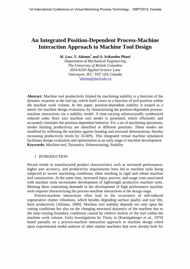
In response to the need for a computationally efficient design methodology which includes the position-dependent machining stability as a criterion for design evaluation; an integrated approach as depicted in the flow chart given in Figure 1 is followed in this paper. Machine concept and requirements once envisaged, dynamic performance of the machine is evaluated in Sec. 2. For a defined set of cutting conditions and productivity levels, the position-dependent machining stability as a function of feed direction is evaluated in Sec. 3. Mechanical parameters limiting productivity are identified and modified to meet target productivity in Sec. 4; followed by the conclusions in Sec. 5.
Figure1; Flow chart of a virtual integrated position-dependent process-machine
interaction approach for designing milling machines ensuring targeted productivity. 2 SUBSTRUCTURALLY SYNTHESIZED REDUCED FE MACHINE MODEL
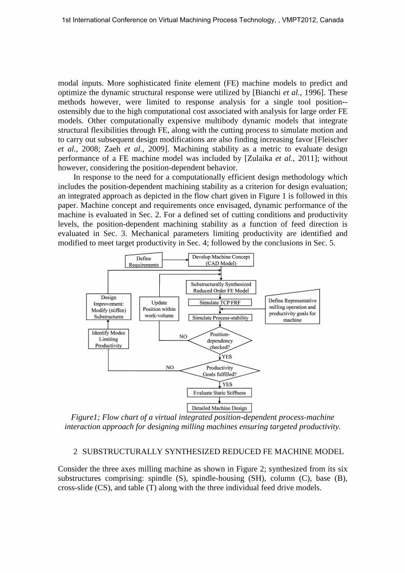
Consider the three axes milling machine as shown in Figure 2; synthesized from its six substructures comprising: spindle (S), spindle-housing (SH), column (C), base (B), cross-slide (CS), and table (T) along with the three individual feed drive models.
1st International Conference on Virtual Machining Process Technology, , VMPT2012, Canada

Figure 2; Substructural synthesis of the machine tool with a multi point constraint
formulation ensuring displacement compatibility at the fixed and moving interfaces.
2.1 Dynamic response after substructuring, reduction and synthesis FE models for the substructures have been generated from their respective CAD models using ten noded solid tetrahedron elements; with material properties assigned as: modulus of Elasticity of 89 GPa; density of 7250 kg/m3; and, Poisson’s ratio of 0.25. Each substructure is reduced independently (retaining only interface degrees of freedom) based on an improved variant of the standard component mode synthesis method; and, combined subsequently by describing displacement compatibility at interfaces (classified in Table I) with sets of algebraic equations using an interpolation multi point constraint formulation, as described completely in [Law et al., 2012].
The undamped equation of motion for the synthesized reduced order model is:
⎣⎢⎢⎢⎡𝑴𝑆 0 0 0 00 𝑴𝐶 0 0 00 0 𝑴𝐵 0 00 0 0 𝑴𝐶𝑆 00 0 0 0 𝑴𝑇⎦
⎥⎥⎥⎤
⎩⎪⎨
⎪⎧�̈�𝑆�̈�𝐶�̈�𝐵�̈�𝐶𝑆�̈�𝑇 ⎭
⎪⎬
⎪⎫
+
⎣⎢⎢⎢⎢⎡𝑲𝑆 + 𝑪𝑇𝜶𝑪 0 0 0 0
0 𝑲𝐶 + 𝑪𝑇𝜶𝑪 0 0 00 0 𝑲𝐵 + 𝑪𝑇𝜶𝑪 0 00 0 0 𝑲𝐶𝑆 + 𝑪𝑇𝜶𝑪 00 0 0 0 𝑲𝑇 + 𝑪𝑇𝜶𝑪⎦
⎥⎥⎥⎥⎤
⎩⎪⎨
⎪⎧𝒖𝑆𝒖𝐶𝒖𝐵𝒖𝐶𝑆𝒖𝑇 ⎭
⎪⎬
⎪⎫
=
⎩⎪⎨
⎪⎧𝒇𝑆𝒇𝐶𝒇𝐵𝒇𝐶𝑆𝒇𝑇 ⎭
⎪⎬
⎪⎫
(1)
where {𝑴,𝑲} are the reduced substructural mass and stiffness matrices; 𝑪(𝒖𝑆,𝒖𝐶 ,𝒖𝐵,𝒖𝐶𝑆,𝒖𝑇) is the displacement operator coupling the substructures, whose coefficients are obtained with an interpolation multi point constraint formulation; and, 𝜶 is a diagonal matrix of penalty numbers, selected as in [Law et al., 2012]. The dynamic response at the tool centre point (TCP) is solved for any desired position, by solving the
1st International Conference on Virtual Machining Process Technology, , VMPT2012, Canada

eigenvalue problem in Eq. (1); by varying the tool position in the work volume by adjusting ∆𝑋,∆𝑌, or ∆𝑍 (see Figure 2).
Direct TCP Frequency Response Functions (FRFs) are compared with that of a full order model at three different tool positions, as shown in Figure 3. The top position is the configuration shown in Figure 2; the mid and bottom positions are when the tool has moved in the Z-direction by an amount of 0.2 m; and 0.4 m respectively. Damping levels for individual modes in the simulated TCP FRFs have been correlated using experimental modal damping from measurements on a similar available machine.
Table I; Division of degrees of freedom by interface type for individual substructures Sp. + Hsg Col. Base Cr. Sl. Table Total
Full order model 13178 16653 32757 24459 10140 97187 Reduced model
Fixed Interface - 312 330 - - 8994 Moving Interface 1010 1221 1615 2598 1908
Figure 3; Comparison of full order model and improved reduced order model (ROM)
TCP FRFs at three different tool positions: top, mid, and bottom.
The strong position-dependent mode shift and amplitude change in the global modes corresponding to the column, the spindle housing, and, the spindle assembly are captured reasonably well by the substructurally synthesized reduced order models, with the exception of the second mode at ~70-75 Hz. Reduction of substructures does not induce much error [Law et al., 2012]; and the underestimation of this mode may be partially attributed to the nature of the interpolation constraint formulation, which can underestimate stiffness at the interfaces [Heirman et al., 2010]. The synthesized reduced model size being 1/11th the size of the full model, leads to considerable simulation time savings. The machine under investigation is envisaged for milling of hard materials and common steel; hence the stability of the machining process will primarily be influenced by the lower frequency structural modes [Zulaika et al., 2011]; hence TCP dynamic response simulations are limited up to 500 Hz.
100 200 300 4000
2
x 10-7
Mag
nitu
de [m
/N]
100 200 300 4000
2
x 10-7
Mag
nitu
de
[m/N
]
Full Order Model Top PositionImproved ROM Top Position
Full Order Model Mid PositionImproved ROM Mid Position
100 200 300 4000
2
x 10-7
Freq. [Hz]
Mag
nitu
de
[m/N
]
Full Order Model Bottom PositionImproved ROM Bottom Position
1st International Conference on Virtual Machining Process Technology, , VMPT2012, Canada

3 POSITION-DEPENDENT PROCESS-STABILITY End milling of AISI 4340 steel is selected as the representative operation that the envisaged machine is designed for. To meet productivity requirements, a minimum depth of cut of 2 mm is targeted in the whole working range of the machine.
It is possible for a multi degree of freedom machine tool to chatter in any of its modes. The effect of each mode is determined by its dynamic characteristics, and the alignment of the force with the direction of the flexibility of the mode. In milling, force directions change as a function of immersion; moreover, the global structural modes may not be aligned with the principal machine directions. The time varying effect of forces is accounted for with the time varying directional dynamic coefficients [Altintas et al., 1995]; and, the projections of modes which are different at each feed direction are accounted for by way of using directional (rotational) matrices [Kilic et al., 2011]. This results in speed/feed independent absolute chatter stability limits which vary across feed directions in proportion to the magnitude of projections of the modes in that direction.
The mass normalized modal vector for each global structural mode 𝑚�𝑖𝑢𝑣 is first projected over the machine tool axes 𝑋𝑀𝑇𝑌𝑀𝑇 (𝑢𝑣), and subsequently over the feed axes (𝑥𝑦) through the angles 𝛽 and 𝜃 respectively, as shown in Figure 4.
Figure 4; Orientation of machine mode 𝑚�𝑖
𝑥𝑦in the machine tool and feed axes The position-dependent stability of the milling system is determined using a modal
model of the machine and the following characteristic equation [Altintas et al., 1995]: 𝑑𝑒𝑡([𝑰] + Λ[𝜱𝑂𝑅(𝑖𝜔𝑐)]) = 0 (2)
where: 𝛬 = 𝛬𝑅 + 𝑖𝛬𝐼 = −1
4𝜋𝑁𝑡𝐾𝑡𝑎�1 − 𝑒−𝑖𝜔𝑐𝑇� (3)
is the eigenvalue of the characteristic equation, 𝛬𝑅 and 𝛬𝐼 are its real and imaginary parts, 𝑁𝑡 is the number of teeth on the cutter, 𝐾t is the cutting force coefficient of the material being cut, 𝑎 is the axial depth of cut, 𝜔𝑐 is the chatter frequency, and, 𝑇 is the tooth passing period. The oriented directional matrix 𝜱𝑂𝑅 is:
[𝜱𝑂𝑅] = [𝜶0]�𝜱𝑥𝑦� (4) where 𝜶0 is the matrix of the average direction factors, determined as in [Altintas et al., 1995], and �𝜱𝑥𝑦� = [𝑻][𝜱𝑢𝑣][𝑻]−1, wherein 𝑻(𝛽, 𝜃) is the transformation matrix obtained as in [Kilic et al., 2011], and, 𝜱𝑢𝑣 is the TCP FRF matrix in the principal 𝑢𝑣 direction. The critically stable depth of cut described by the parameters in Eq. (3) is:
𝑎𝑙𝑖𝑚 = −
2𝜋𝛬𝑅𝑁𝑡𝐾𝑡
�1 + �𝛬𝐼𝛬𝑅�2
� (5)
1st International Conference on Virtual Machining Process Technology, , VMPT2012, Canada

3.1 Process-stability and modes limiting productivity Stability was simulated for down milling AISI 4340 steel with 75% immersion with an end mill of 20 mm diameter, with 𝑁𝑡 = 6; 𝐾𝑡 = 3000 MPa; and the radial coefficient, 𝐾𝑟= 0.24. The stability curves are simulated for the tool positions described earlier, i.e. top, mid and bottom positions for all machining directions; results of which are shown in Figure 5, which also compares the corresponding chatter frequencies.
Figure 5; Feed directional stability (left) at three different tool positions: top, mid, and bottom, and corresponding chatter frequencies as a function of feed direction (right).
In Figure 5 (left), the regions inside the stability curve envelopes are stable, and
those outside, are unstable. The limiting depth of cut is plotted radially, while the machining (feed) directions are plotted circumferentially. The stability curves are symmetric about 45º and 135º respectively, i.e. in directions where the mode under consideration halves the angle between the 𝑢𝑣 principal directions. The shape and envelope of the stability boundaries are a strong function of the engagement conditions; becoming a circle for full immersion milling. Absolute limits exhibit a strong position-dependent behavior. The minimum stability limit of 1.32 mm at ~20º feed orientation with a chatter frequency of ~75 Hz corresponds to the situation when the tool is closest to table top. This chatter frequency of ~75 Hz corresponds to the global torsional mode of the column; which is most compliant at the bottom position. Moreover, as shown in Figure 5 (right), the chatter frequencies for almost all feed directions at all three tool positions lie in between the first two dominant global modes, making them candidate modes to be modified (stiffened) such as to increase the absolute minimum limit to attain the target productivity goal. Moreover, the static stiffness evaluated from the Y-intercept in Figure 3, ranges from 14-16 N/µm, depending upon the tool position. This is well below the required threshold of 20 N/µm at the TCP [Zulaika et al., 2011] for milling machines as being envisaged, thus further warranting design modifications.
4 DESIGN MODIFICATIONS
In order to achieve the target productivity goal, the dynamic stiffness of the modes limiting productivity is increased by stiffening the column substructure against bending and torsional deformations through addition of stiffeners as shown in Figure 6 (left).
0 100 200 30050
60
70
80
Feed Orientation [°]Ch
atte
r Fre
q. [H
z]
Chatter Freq. as a function of Feed Direction
Top PositionMid PositionBottom Position
1st International Conference on Virtual Machining Process Technology, , VMPT2012, Canada

Figure 6; Comparison of original and modified column (left) and the corresponding
TCP FRFs between original and the modified machine model (right). An increase of the dynamic stiffness by ~30% for the first two dominant modes due
to stiffening is evident from TCP FRF comparisons in Figure 6 (right). The static stiffness for the modified machine design now ranges from 21-23 N/µm (depending on tool position), an increase of ~50% over the previous range of 14-16 N/µm.
4.1 Position-dependent process-stability for improved design Stability was simulated with the same cutting conditions as before, but with the modified machine position-dependent response; results of which are compared with the results from the original machine model in Figure 7. An increase by as much as ~35-60 % in the absolute limiting depth of cut at all three tool positions is achieved; meeting the target productivity level of ~2 mm for any machining direction within the work volume. In addition to the absolute lower limit being increased, the envelope of the curve also shows an increase, leading to higher absolute stability limit for a wider range of feed directions.
Figure 7; Feed directional stability comparison for original and modified machine model at three different tool positions: top (left); mid (middle); and bottom (right).
The improvements in the stability limits are sensitive to the level of modal damping
in the model; with higher damping levels increasing the stability limit.
100 200 300 4000
0.5
1
1.5
2
2.5x 10⁻⁷ Comparison of TCP FRFs at TOP Position
Freq. [Hz]
Mag
nitu
de [m
/N]
Original Machine DesignModified Machine Design
1st International Conference on Virtual Machining Process Technology, , VMPT2012, Canada

5 CONCLUSIONS A time-varying structural dynamics model is presented which can efficiently and accurately simulate the dynamic response of a representative three axis milling machine for any tool position within the machine work volume. For a representative machining operation, position-dependent stability was evaluated for all machining directions; and critical modes limiting productivity were identified. The substructural components corresponding to these critical modes were modified to increase their resistance to bending and torsional deformations. The static and dynamic stiffness of the critical machine modes was increased by 50% and ~30% respectively, which translate to ~35 – 60% increase in the absolute stability limit. This integrated virtual machine simulation facilitates design evaluation and optimization at an early stage of machine development.
6 ACKNOWLEDGMENT This research has been supported by the NSERC CANRIMT Research Grant.
REFERENCES [Altintas, 2000] Altintas, Y.; "Manufacturing Automation: Metal Cutting Mechanics,
Machine Tool Vibrations, and CNC Design", Cambridge University Press; 2000 [Altintas et al., 1995] Altintas, Y. and E. Budak; "Analytical prediction of stability
lobes in milling." CIRP Annals-Manufacturing Technology 44: 357-362; 1995 [Bianchi et al., 1996] Bianchi, G., F. Paolucci, et. al.; "Towards virtual engineering in
machine tool design." CIRP Annals 45: 381-384; 1996 [Fleischer et al., 2008] Fleischer, J., C. Munzinger and M. Trondle; "Sim. and Opt. of
Complete Mech. Behavior of M/c Tools." Prod. Eng. R&D 2: 85-90; 2008 [Heirman et al., 2010] Heirman, G. and W. Desmet; "Interface reduction of flexible
bodies for efficient modeling of body flexibility in multibody dynamics." Multibody System Dynamics 24: 219-234; 2010
[Kilic et al., 2011] Kilic, Z. M. and Y. Altintas; "Effect of Unmatched Spindle Dynamics on the Material Removal Rates in Milling Operations". The Proceedings of MTTRF 2011 Meeting, Chicago, Illinois, U.S.A; 2011
[Koenigsberger et al., 1970] Koenigsberger, F. and J. Tlusty; "Machine Tool Structures, Volume 1", Pergamon Press; 1970
[Law et al., 2012] Law, M., Y. Altintas and A. S. Phani; "Position-Dependent Multibody Dynamic Modeling of M/c Tools Based on Improved Reduced Order Models". Proceedings of NAMRI/ SME, Vol. 40, To Appear; 2012
[Zaeh et al., 2009] Zaeh, M. F. and F. Schwarz; "Implementation of a Process and Structure Model for Turning Operations." Prod. Eng. R&D 3: 197-205; 2009
[Zulaika et al., 2011] Zulaika, J. J., F. J. Campa and L. N. Lopez de Lacalle; "An integrated process–machine approach for designing productive and lightweight milling machines." Int. J of Machine Tools and Manufacture 51: 591-604; 2011
1st International Conference on Virtual Machining Process Technology, , VMPT2012, Canada