an innovative technology in concrete construction: semi
TRANSCRIPT

An Innovative Technologyin Concrete Construction:
Semi-Automated Rebar Tying
by
Frank Robert Altobelli
B.S. Civil Engineering, University of Maryland(1989)
Submitted to the Department of Civil Engineeringin Partial Fulfillment of the Requirements For the Degree of
Master of Science in Civil Engineering
at the
Massachusetts Institute of TechnologyFebruary 20, 1991
Copyright Massachusetts Institute of Technology 1991All Rights Reserved
Signature of AuthorDepartment of Civil Engineering
February 20, 1991
Certified byI Fred Moavenzadeh
Director, Center for Construction Research and EducationThesis Supervisor
Certified byCarl Peterson
Associate Professor of Mechanical EngineeringThesis Supervisor
Accepted byOle S. Madsen
Chairman, Departmental Committee on Graduate Studies

An Innovative Technology in Concrete Construction:Semi-Automated Rebar Tying
by
Frank Robert Altobelli
Submitted to the Department of Civil Engineeringin partial fulfillment of the requirements or the degree of
Master of Science in Civil Engineering
Abstract
The two main purposes of this thesis are to present the design of a new prototyperebar tying tool and to characterize technological development in concreteconstruction.
The technologies of concrete construction have undergone gradual, evolutionarychanges since concrete became a popular material for construction. Furthermore,these technological developments can be characterized as an active, industry-wideprogression from fully manual operations to fully automated operations. This thesiswill present a snapshot of the current state of the art in concrete technology, as wellas illustrating the major steps that individual technologies have taken on theirevolution to the present status.
The thesis continues with a chapter covering an analysis of the task of rebar tying,which contains examples of other unsuccessful attempts to automate the task. Thefunctional requirements and design criteria for an improved semi-automated rebartying machine are then presented. A new prototype rebar tying tool has beendesigned based on the developed requirements. The operation of the pneumaticdevice and its detailed design is included in Chapter 4.
Thesis Supervisors:
Fred MoavenzadehDirector, Center for Construction Research and Education
Carl PetersonAssociate Professor of Mechanical Engineering

Acknowledgements
I wish to express my sincere appreciation and thanks to the following persons for
their help and support of my work.
Professor Fred Moavenzadeh, who served as co-advisor on this thesis, contributed
many ideas, and provided direction for the thesis.
Professor Carl Peterson, who served as co-advisor on this thesis and contributed
priceless wisdom in the design of the tool.
The U.S. Army Research Office, for providing funding for me through the Program
for Advanced Construction Technology.

Table of Contents
Chapter 1 - Introduction ......................................... 7
1.1 Overview and Purpose ................................... 7
1.2 Brief History of Concrete Usage ........................... 7
1.3 Economics of Concrete Construction ........................ 91.4 Economics of Rebar Tying ........................ ..... 10
1.5 Potential Impacts of Semi-Automated Rebar Tying ............. 101.6 Automated Rebar Tying for Fully Automated Rebar Fabrication ... 12
Chapter 2 - Technological Developments in Concrete Construction ......... 14
2.1 Characterization of Technological Developments in ConcreteConstruction................. ........................ 14
2.2 Innovations in Concrete Product Technology .................. 15
2.3 Innovations in Concrete Process Technology .................. 21
2.4 Summary .............................................. 33
Chapter 3 - Analysis of the Task of Rebar Tying........................ 34
3.1 Introduction to Rebar Tying............................................ 34
3.2 Other Methods for Joining Rebar ........................... 34
3.3 Functional Description and Requirements for the Task of Rebar Tying 373.4 Analysis of Previous Embodiments .......................... 45
Chapter 4 - Design of an Improved Rebar Tying Mechanism ............... 49
4.1 Introduction to the Design of the Device ...................... 494.2 Overall Design of the Device................................... 494.3 Operation of the Device ................................... 544.4 Detailed Design of the Wire Feeding and Loop Forming Mechanism 634.5 Detailed Design of the Wire Tensioning and Twisting Mechanism .. 64
Chapter 5 - Conclusions and Recommendations .......................... 66
5.1 Summary of Work ...................................... 66
5.2 Suggestions for Further Work.............................. 67

Appendix 1 - Portland Cement Varieties ............................... 68
Appendix 2- Admixtures .......................................... 69
Appendix 3 - Patented Tying Devices ................................ 70
Appendix 4 - Assembly Drawing .................................... 71
Appendix 5 - End of Wire Tensioning and Twisting Cylinder ............... 72
Bibliography ..................................................... 73
List of Figures
Figure 3 - 1 Clipped Connections ..................................... 35
Figure 3 - 2 Connection Types ....................................... 39
Figure 3 - 3 Types of Ties ......................................... 41
Figure 3 - 4 Tie Wire and Twisting Tools ............................. 43
Figure 4 - 1 Prototype Tebar Tying Tool .............................. 50
Figure 4 - 2 Prototype Staple Tie Geometry ............................ 52
Figure 4 - 3 Step One - Positioning .................................. 55
Figure 4 - 4 Step Two - Lower Twisting Mechanism ................. ... 56
Figure 4 - 5 Step Three - Staple Feeding .............................. 57
Figure 4 - 6 Step Four - Secure Ends of Staple ........................... 58
Figure 4 - 7 Step Five - Retract Twisting Mechanism .............. ....... 59
Figure 4 - 8 Step Six - Twist Tie .................................... 60
Figure 4 -9 Step Seven - Release Tie ................................ 61
Figure 4 - 10 Step Eight - Retraction and Reset .......................... 62

CHAPTER 1INTRODUCTION
1.1 Overview and Purpose
One operation in the construction of reinforced concrete is the assembly of
reinforcing bars. The reinforcing steel, known as rebar, is assembled by hand tying
the intersections of the bars with wire. Since a majority of concrete construction is
flatwork, workers are required to bend over for long periods of time while
assembling the reinforcement.
The two main purposes of this thesis are to characterize technological innovation in
concrete construction and to present the design of an innovative, semi-automated
rebar tying machine for concrete construction. The device will enable a worker to tie
rebar from a standing position, thereby eliminating the grueling aspect of the task,
bending over for long periods of time. It will also allow lower skilled, lower cost
labor to perform the task at higher levels of worker productivity and with improved
consistency and quality of the finished product.
This chapter will first present a brief history of concrete usage, depicting the rich
heritage of concrete construction worldwide. The economics of the concrete industry
and of rebar tying in particular will then be discussed, followed by a look at some of
the potential impacts of the innovative device presented here.
1.2 Brief History of Concrete Usage
Concrete, one of the oldest building materials in use today, was first used over two
thousand years ago by the Romans in the construction of buildings, bridges, and other
structures. One notable structure is the Pantheon in Rome, with its cast-in-place
concrete "Great Dome," which still stands today. The Romans used cast-in-place
concrete for the underwater construction of quay walls and small jetties, and used

precast concrete blocks to build large jetties.' After the fall of the Roman Empire,concrete usage virtually disappeared until 1756, when English engineer John
Smeaton used it to build Eddystone Lighthouse off the coast of Plymouth, England.
Reinforced concrete came into use in the 1800's, with patents issued to numerous
inventors. Perhaps the most famous of the early inventors is the well known Joseph
Monier, who received a patent in 1867 for reinforced concrete flower pots. Monier
would later receive additional patents for floors, beams, pipes, bridges, and other
items. Although Monier received the most recognition, he was not the first to receive
a patent for reinforced concrete. Earlier patent recipients included Lambot in 1855
for a reinforced concrete boat, Francois Coignet in 1861, and Hyatt for reinforced
concrete beams. 2
In the United States, unreinforced concrete buildings began to appear as early as
1835. The William Ward House, which is believed to be the country's first cast-in-
place reinforced concrete structure, was constructed shortly after. It was built in Port
Chester, New York, and was completed in 1875. 3 Today, concrete, wood, and steel
remain the three most commonly used materials in construction.
Concrete's popularity can be attributed to its favorable engineering and aesthetic
properties. In addition to being strong and stiff, it is durable and corrosion resistant.
Architecturally, it can be fashioned into an almost infinite number of shapes having
numerous surface finishes.
Concrete is economical for a multitude of applications. The components, sand,gravel, and portland cement, are widely available and can usually be produced fromlocal materials. In addition, concrete is much easier and less expensive to processthan steel. With increasing emphasis being placed on the lifecycle costs of structures,it is likely that concrete, which requires little maintenance and is extremely durable,
I Hans Straub, A History of Civil Engineering, (Cambridge, MA: The MIT Press. 1964),pp. 20-21.
2Ibid, pg. 209.
3Edward Cohen and Raymond C. Heun, "100 Years of Concrete Building Construction inthe United States," Concrete International, March, 1979.
will grow in popularity and use for major projects.
In recent years, concrete has been showcased in the finest structures built. Concrete
is the primary structural material in thirty-five percent of projects nominated for
ASCE Outstanding Engineering Achievement Awards over the past three years, and
is a substantial component in another thirty-five percent.
1.3 Economics of Concrete Construction
In addition to concrete's importance as a durable, economical construction material,
and its rich history as an engineering and architectural building component, the
concrete construction industry is important to the nation's economy. Concrete
construction is roughly a 15 billion dollar per year industry, 4 or about 3.6 percent of
the 414 billion dollar per year construction industry.5 There are over 23,000 concrete
construction firms in the industry, employing over 200,000 workers. 6 The health of
the industry will therefore affect the health of the overall economy and the lives of
many American workers. These economic realities provide some of the motivation
for the development of innovative, productivity enhancing technologies in concrete
construction.
Given the economic importance of concrete construction, one wonders how in 1987,
concrete construction contractors spent 3.3 billion dollars on direct labor costs, but
just 200 million dollars was spent on machinery and equipment. 7 It would seem that
there is little investment in labor saving equipment and devices. However, the next
chapter will portray the evolution of technologies for concrete construction, showing
4U.S. Department of Commerce, Bureau of the Census, 1987 Census of ConstructionIndustries, "United States Summary, Establishments With and Without Payroll," p. 7.
5U.S. Department of Commerce, Bureau of the Census, Current Construction Reports,"Value of New Construction Put in Place," April, 1990, p. 3.
6U. S. Department of Commerce, Bureau of the Census, 1987 Census of ConstructionIndustries, "Concrete Work Special Trade Contractors, Industry 1771," p. 2.
7U. S. Department of Commerce, Bureau of the Census, 1987 Census of ConstructionIndustries, "Concrete Work Special Trade Contractors, Industry 1771," p. 6-7.

that indeed the technology is developing and is being adopted by the industry, and
that the industry is shifting emphasis to mechanized and automated operations.
1.4 Economics of Rebar Tying
Each year, 90 million tons of portland cement, over 5 million tons of reinforcing
bars, and 530 million tons of aggregate are used in the production of 655 million tons
of concrete. 8 (Aggregate weight was computed by using an estimate of the weight of
fresh concrete.)9 Means' Concrete Cost Data. 1990 lists the unit cost of placing one
ton of reinforcing steel at $440.00 for lots averaging ten tons, and $325.00 for lots
over fifty tons.' 0 If Means is correct, then between 1.625 and 2.2 billion dollars is
spent each year to place and tie rebar.
If a labor saving device, such as a semi-automated rebar tying machine, could be
developed, and direct labor costs could be reduced by ten percent, the resulting yearly
savings would be between 162 and 220 million dollars!
1.5 Potential Impacts of Semi-Automated Rebar Tying
1.5.1 Effect on Competitiveness of Concrete
Since the primary basis of competition in the concrete construction industry is price,
any cost savings that could be achieved would improve the industry's ability to
compete against substitute products. Reinforced concrete competes against steel for
structural uses. There are really no other feasible materials for structures of
reasonable size. The decision of whether or not to use concrete (structural, not
architectural) is one of economics. The least expensive system is usually chosen.
Decreased cost for concrete will therefore improve its strategic position in the overall
8U. S. Department of Commerce, International Trade Administration, "ConstructionReview," May-June, 1990, p. 47.
9Portland Cement Association, Design and Control of Concrete Mixtures. Twelfth Edition,1979.
toWilliam D. Mahoney, Editor, Means Construction Cost Data, 1990, p. 63.

construction industry.
1.5.2 Effect on Workers and Worker Productivity
The design to be presented of the prototype rebar tying device allows the tying
operation to be performed from a standing position. This will reduce the occurrence
of repetitive stress injuries to the backs of workers. In addition, fatigue will not slow
worker production near the end of a shift, when typically the effects of prolonged
bending over are most pronounced, resulting in increased productivity of the tying
operation.
Another impact that the device will have on workers is that it will allow lower skilled
labor to perform rebar tying at the same or greater levels of productivity as skilled
steel workers. In effect, some of the skill in the task is being shifted from the worker
to the machine, providing greater job opportunities for lower skilled workers, and
allowing higher skilled workers to do less repetitive work, and work that is ill suited
to the device.
1.5.3 Economic Impacts
It is very difficult to discuss the economic impacts of productivity increases in
quantitative terms. One problem is with what productivity to measure. The task of
rebar tying is simply a sub-task of the reinforcement placing operation. It is desirable
to improve this overall operation, not the tying task. While one can design a device
to perform tying in a specified amount of time (improving tying efficiency), it is
difficult if not impossible to numerically predict the effect on the overall operation
without making quantitative assumptions of how the new method will interact with
the overall operation. Similarly, since cost data is compiled for the placement of
reinforcement, not the sub-task of rebar tying, meaningful quantitative predictions of
cost savings (from enhanced productivity) cannot be made.
Qualitative estimates of cost savings from increased productivity can be made. The
device will have the greatest impact on applications with horizontally placed
reinforcing steel, including slabs, floors, and bridge decks, that traditionally would
have required the worker to bend over to place the steel. Since about 75% of
concrete work is horizontal construction, the impact of the device should be
widespread.
An interesting finding is that the cost per pound to place reinforcing steel is almost
identical for all applications except columns and waffle slabs, where it is about 30%
more expensive.1 " It seems that the cost of placing reinforcement for a concrete
structure is independent of the type of structure and almost entirely dependent on the
quantity of reinforcement to be placed. Therefore, highly reinforced structures will
become more economical than before, while lightly reinforced components will
realize less cost savings.
The greatest cost impact is likely to be from the use of lower cost labor, made
possible by the lower skill level required with the device. Quantitative predictions
can be made regarding cost savings from the use of lower cost labor. A twenty city
average of union pay scales showed that reinforcing ironworkers are paid $25.31 per
hour, while skilled laborers received only $18.46 per hour.12 If only half of the
ironworkers were replaced with laborers, a 13.5 % savings would be realized,
resulting in an industry wide savings of between 220 and 300 million dollars.
1.6 Automated Rebar Tying for Fully Automated Rebar Fabrication
In Chapter 2, technological innovation in concrete construction will be characterized
as an active, industry-wide progression from fully manual operations to fully
automated operations. The automation of rebar tying will represent a significant step
toward that goal. It is feasible that in a few years, fully automated precast plants may
be in operation. Automated site operations may become widespread. For total
process automation to be possible, automated rebar tying or some other automated
joining method must be developed.
The proposed device is a semi-automated, manually operated machine, but it is by no
means limited to that mode of operation. It is expected that subsequent versions of
the device will be adapted for use in a totally automated rebar fabrication machine,
with integrated rebar cutting, bending, and tying. Currently, automated systems for
11William D. Mahoney, Editor. Means Concrete Cost Data. 1990.
12 WIlliam G. Krizan and Steven W. Setzer, "Wage Hikes Fall Below Inflation," ENR ThirdQuarterly Cost Report, September 27, 1990.

bending and cutting rebar are being developed. Once the mechanization of the rebar
tying task is completed, it can be integrated with the other processes to create a fully
automated, computer controlled system for fabricating rebar.

CHAPTER 2TECHNOLOGICAL DEVELOPMENTS
IN CONCRETE CONSTRUCTION
2.1 Characterization of Technological Developments in ConcreteConstruction
Technologies are often classified as product technologies and process technologies.
When concrete technologies are examined using such a model, distinct
characterizations of technological development in each category can be made. Both
types of technology have developed in a similar, evolutionary manner. Continual,
incremental improvements have occurred to both product and process technologies.
However, the characterizations of the types of improvements which have been made
to each class of technology are different.
The development of product technology can be characterized as an expansive
development. In other words, the types and characteristics of concrete products have
been continually developing, creating more and different varieties of concrete with
increased capabilities. The result is the utilization of concrete products for an
expanded number of construction applications. New product technologies in concrete
construction include such things as new types of portland cement, new additives and
admixtures, fiber reinforcement, precast concrete, prestressed concrete, etc.
Process technologies in concrete construction show a slightly different trend. A
model for the development of process technologies which seems to apply nicely to
concrete construction is the model for process automation. The successful
automation of a process is inherently easier if the process is already highly
mechanized. In this case, the problem of automating the task simplifies to a problem
of developing system logic and controls. Typically, the development of process
automation is accomplished by taking a manual operation, mechanizing it, improving
the mechanization, and finally taking the operation out of the hands of the machine
operator through total automation.
14

The process technologies of concrete construction can be shown to conform to this
model. They have undergone gradual, evolutionary changes since concrete became a
popular material for construction. Furthermore, the developments can be
characterized as an active, industry-wide progression from fully manual operations to
fully automated operations. Although some processes are still performed manually,
most have undergone some degree of mechanization, and many have progressed to
the automation stage.
Another trend in process technologies, which will be referred to throughout this
chapter, is the elimination of some of the processes in the concrete construction
operation. The use of mechanized and automated methods sometimes makes other
steps in the process unnecessary. Examples of construction methods that eliminate
steps in the process include use of prefabricated welded reinforcing mats,
slipforming, and tilt-up construction.
This chapter will present a snapshot of the current state of the art in concrete
technology. In addition, the major steps that each individual technology has taken on
its evolution to the present status will be illustrated, emphasizing the different
characterizations of development in each class of technology. Although
developments in product and process technologies necessarily impact each other, they
will be discussed separately below.
2.2 Innovations in Concrete Product Technology
2.2.1 Concrete Design
Structural design technology has advanced considerably. One of the earliest designs
for a reinforced concrete beam was by Hyatt, who through intuition or an "educated"
guess, correctly placed the reinforcing steel in the tension side of the beam.' 3 Today,
we have a vast amount of knowledge of the mechanics of reinforced concrete,
resulting from years of research, and can produce designs to resist gravity, wind, and
seismic loads.
1 3 Hans Straub, A History of Civil Engineering, The MIT Press, Cambridge, MA, 1964, pg. 209.

Advances in concrete design have also produced entirely new configurations of
concrete and reinforcement. As early as 1923, a water tank was "prestressed" by
using adjustable bands. Two years later, in 1925, the first post-tensioning system for
embedded reinforcing bars received a patent. However, it wasn't until 1938 that the
first "real" prestressed structure, a shell dome, was built. Prestressed concrete was
first used in bridge construction in the United States in 1949, for the Walnut Lane
Bridge. In the following year, the first prestressed pavement was constructed.' 4
Widely used today, prestressed concrete is typically reinforced with very high
strength stranded wire (about four times as strong as the steel in conventionally
reinforced concrete), although high strength prestressing rods are sometimes used.
An innovative application of prestressing technology that is gaining popularity is the
external prestressing of concrete members that are in need of repair or are found to be
inadequate.
The development of prestressed concrete has expanded the use of concrete. More
applications are possible since prestressed concrete allows the design of lighter
members and it allows the designer to control deflections.
2.2.2 Concrete Mix Design
"The goal of practical mix design is to develop a concrete that can be produced,
transported, and placed efficiently and consistently to obtain the specified in-situ
quality.""15 As production, transportation, placement, and finishing technologies have
evolved, new mix designs have been developed to meet the changing requirements.
One of the most exciting areas of concrete mix design that continues to develop is the
design of high strength mixes. High strength concrete mixes have been produced to
enable the construction of concrete structures with very highly stressed members that
would be impossible with lower strength concrete.
14 "Memorable Miscellany," Concrete International, October, 1979.
15 Hanne Ronneberg and Malvin Sandvik, "High Strength Concrete for North Sea Platforms,"Concrete International, January, 1990.

It is interesting how the notion of "high strength" has evolved coincident with the
development of higher and higher strength mixes. In 1958, high strength concrete
(6000 psi) was used to reduce the required size of columns in a Dallas apartment
building. In 1973, a strength of 7500 psi was used for One Thousand Lake Shore
Plaza in Chicago. The following year, 12000 psi high strength concrete was
developed.' 6 Currently, concrete strengths of greater than 9000 psi are considered
high strength and state-of-the-art high strength mixes achieve strengths of up to
17000 psi.
2.2.3 Portland Cement
Until 1824, only natural cements extracted from pozzuolanic soils (found in regions
rich in volcanic deposits) were used to make concrete. In October of that year,
Joseph Aspdin applied for a patent for artificial cement. He named the cement
"Portland Cement," because it resembled a commonly used building material,
Portland Stone. 17
Numerous varieties of portland cement have been developed in response to widely
differing special applications and design requirements. A fairly extensive list has
been compiled of different varieties of portland cement and their particular
applications. It is presented in Appendix 1, but will not be discussed in detail here.
2.2.4 Aggregate
Seventy-five percent of the volume of reinforced concrete is aggregate. Originally,aggregates were quarried from natural sand and gravel deposits. However, theincreasing difficulty of finding readily accessible deposits led to the development and
use of crushed stone aggregates. Today, about 50% of the aggregate used in concreteis crushed stone.
16 Jaime Moreno, "225 W. Wacker Drive," Concrete International, January, 1990.
17 Hans Straub, A History of Civil Engineering, The MIT Press, Cambridge, MA, 1964, pg 207.

Although standard weight aggregates are used almost exclusively, lightweight
aggregates have been developed for special applications of lightweight structural
concrete. Slag was first studied for use in concrete in 1917, and today expanded slag
is one form of lightweight aggregate. 18 In 1918, expanded shale aggregate, the first
synthetic lightweight aggregate, was patented by Stephen Hayde.' 9 Other synthetic
lightweight aggregates include expanded clay and expanded slate. 20 Very lightweight
aggregates have been developed for use in lightweight, low strength, insulating
concrete. Such aggregates include perlite, vermiculite, and expanded
polystyrene beads. 21
Similarly, heavyweight aggregates have been developed for special applications of
heavyweight concrete including radiation shielding and counterweights for movable
bridges. High density aggregates include barite, ferrophosphorus, goethite, hematite,
limonite, magnetite, lead, and steel shot.22
2.2.5 Additives and Admixtures
Additives encompasses a wide range of materials which have been developed to
enhance the properties and performance of concrete. Admixture research began in
the twenties. In the mid-thirties, it was found that air-entrainment increased the
durability of concrete, 23 and by the forties, vinsol resin was being used for air-
entrainment. As early as 1936, pozzolan was used in concrete for the Bonneville
18 "Memorable Miscellany," Concrete International, October, 1979.
19 Edward Cohen and Raymond C. Heun. "100 Years of Concrete Building Construction inthe United States," Concrete International, March, 1979.
20 Joseph J. Waddell, Editor, Concrete Construction Handbook, McGraw-Hill BookCompany, New York, 1968.
21 Design and Control of Concrete Mixtures, Twelfth Edition, Portland Cement Association,Skokie, Illinois, 1979, pg. 128.
22 Ibid, pg. 132.
23 Edward Cohen and Raymond C. Heun. "100 Years of Concrete Building Construction inthe United States," Concrete International, March, 1979.

Dam.?2 In the mid-fifties, set-retarding admixtures were developed. By 1971,
melamime resin was being studied as a water-reducing, high strength additive. In the
early seventies, polymer concretes were developed.2
Today, admixtures provide the construction professional increased flexibility of
construction practices and the mix designer the ability to create higher quality mixes
and special purpose mixes. Commonly used admixtures and their primary purposes
are presented in Appendix 2.
2.2.6 Reinforcement
In addition to the development of prestressed concrete, as mentioned above, other
developments in reinforcing technology have been made. Prior to 1926, reinforcing
steel was highly non-uniform. In 1926, standards for reinforcing steel were accepted.
The standards allowed the use of one grade of steel rather than three, and of eleven
sizes of rebar rather than twenty-six. 26 In 1940, Carl Menzel patented a prototype of
the modem, deformed reinforcing bars used today.27 Currently, eleven standard bar
sizes are still accepted, and the overwhelming majority of rebar is grade 60 steel,
although some grade 75 steel may also be used.
Other materials have been developed to reinforce concrete. These include smooth
steel bars, various types of fibers (discussed in detail below), and bamboo in some
undeveloped countries. Epoxy coatings have been developed for rebar in
applications where corrosion resistance is a concern, and is standard on many bridges.
Composite prestressing tendons made of glass fibers and polyester resin have been
developed and have been used in highly corrosive environments for some bridge
components and for precast elements of a brine tank.28
24 "Memorable Miscellany," Concrete International, October, 1979.
25 Ibid.
26 "Memorable Miscellany," Concrete International, October, 1979.
27 Edward Cohen and Raymond C. Heun. "100 Years of Concrete Building Construction inthe United States," Concrete International, March, 1979.
28 Reinhard Wolff and Hans-Joachim Miesseler, "New Materials for Prestressing andMonitoring Heavy Structures," Concrete International, September, 1989, pp. 86-89.
19

Secondary reinforcement to control the spread of cracks traditionally consisted of
welded wire mesh or deformed welded wire mesh. Fiber reinforcement is now often
used in its place. Research on concrete reinforced with nylon fibers began in the late
sixties. Glass fibers were reported to be successfully used in concrete by 1969, the
same year that a patent was issued for a steel fiber reinforcing method. By 1971, the
first fiber reinforced pavement was constructed in Ohio. 29 Other fibrous materials
which have been proposed include wood and polypropylene.
2.2.7 Precast Concrete
While precast concrete can be thought of as a process which speeds concrete
construction through utilization of off-site production, it will be considered as a
concrete product in this thesis. Precast concrete, as mentioned in Chapter 1, was used
over 2000 years ago by the Romans. Thomas Edison is responsible for one of the
earliest modem day uses of precast concrete in the United States in his effort to
produce affordable low-income homes. The project consisted of the construction of
eleven two-story houses, called the Edison houses, in Union, New Jersey, in 1902.
This was the first use of concrete for industrialized housing.30
By 1917, precast concrete construction was used for a wide variety of structures.31
The development of the technology to date has resulted in the widespread availability
of numerous standard shapes for applications as varied as bridge girders, floor slabs,
pipes, culverts, and manholes.
Developments in concrete product technology has expanded the use and applicability
of concrete in construction. New process technology, however, has made widespread
concrete use possible. If mechanized and automated technologies had not been
developed, concrete use would have been limited by the high cost of manual
methods.
29 "Memorable Miscellany," Concrete International, October, 1979.
30 Edward Cohen and Raymond C. Heun. "100 Years of Concrete Building Construction in theUnited States," Concrete International, March, 1979.
31 "Memorable Miscellany," Concrete International, October, 1979.

2.3 Innovations in Concrete Process Technology
2.3.1 Structural Design and Detailing
The process of concrete construction can be said to begin with the design engineer,
for without a good design and construction drawings to communicate it, the
remaining processes would proceed without direction. The design process has
progressed a great deal since Hyatt received his first patent many years ago. In fact,
the design process has been completely rationalized. Currently the limit states design
methodology, which was first proposed in the fifties and was fully accepted in the
1971 code, 32 is the established benchmark for design.
Reinforced concrete design has developed into a highly mechanized and automated
process. Initially, all design calculations were done by hand. Now, computer aided
detailing and computer programs for analysis and design, both introduced in the early
sixties,33 are in widespread use and have radically changed the way concrete is
designed and construction details are drawn. Today, libraries of computer software
programs are available for concrete design. In addition to the many commercial
vendors of concrete design software, the American Concrete Institute and the
Concrete Reinforcing Steel Institute each offer their own sanctioned software
programs.
2.3.2 Concrete Mix Design
Mix design has developed from a simple recipe for making concrete from sand,
gravel, cement, and water, to a complex technique for specifying proportions of
materials from a vast array of available materials, additives, and admixtures, to obtain
desired material properties as economically as possible. It is not surprising, then, that
computer programs have been written to aid the mix designer in this difficult task.
One such program has been used to develop pumpable mixes for the Al Wehdah
tunnel project in Jordan, where the batch plant had several storage bins containing
aggregates having different unit weights and surface moisture contents. The
spreadsheet program greatly simplified the mix design process, automating some of
32 "Memorable Miscellany," Concrete International, October, 1979.
33 Edward Cohen and Raymond C. Heun. "100 Years of Concrete Building Construction inthe United States," Concrete International, March, 1979.
21

the laborious calculations that would have otherwise been necessary to solve for the
mixing water and cement volumes. 34 (The solution requires an iterative approach.
The spreadsheet was programmed to perform ten calculation loops every time the
recalculate key was pressed, automating the calculations and making them invisible
to the user.)
2.3.3 Manufacturing of Portland Cement
In Joseph Aspin's day, portland cement was processed in much the same way as it is
today, albeit using manual methods rather than automated ones. It took quite awhile
for the production processes to mature. Consequently, manufactured cement did not
become readily available until about 1870. In 1902, Thomas Edison advanced the
process technology when he made vast improvements to the rotary kiln, the primary
machine used in the manufacturing of portland cement.3 5
Different varieties of cement have developed over time and are produced by altering
the process parameters. Today, portland cement is produced in numerous varieties in
modem, fully automated plants with centralized process control.
2.3.4 Aggregate Production
Aggregate production technology necessarily achieved rapid mechanization due to
the lack of satisfactory manual production methods. In 1858, the first machine in
America for the manufacturing of crushed stone was introduced.36 Equipment used
in aggregate production includes feeders, hoppers, crushers, conveyors, grading
screens, washing plants, and storage bins.
Aggregate production is essentially fully automated. However, manually operated
loaders, shovels, draglines, and other bulk material handling machines are used to
supply the production equipment. Typically, the excavated material is loaded onto
large offroad dumptrucks which carry it to the crusher plant. A new method which is
34 Kurt F. Peyfuss, "Simplifying Concrete Mix Design with the PC," Concrete International,December, 1990.
35 Edward Cohen and Raymond C. Heun. "100 Years of Concrete Building Construction inthe United States," Concrete International, March, 1979.
36 Hans Straub, A History of Civil Engineering, The MIT Press, Cambridge, MA, 1964, pg 207.
22

gaining popularity is in-pit crushing.3 7 In-pit crushing utilizes movable crushing
equipment, which is loaded by material handling equipment in the quarry pit. The
crushing equipment feeds the crushed stone onto conveyors, which automatically
transport the material out of the pit. This new method eliminates the step of hauling
the material with dumptrucks.
The two methods of producing lightweight aggregate, the rotary-kiln method and the
sintering process, are also fully automated.
2.3.5 Fabrication and Placement of Reinforcing Steel
Reinforcing bars are produced in highly mechanized and automated steel mills
(typical of all raw steel products). They are usually rolled and cut to 60 foot lengths.
Fabrication of the rebar into desired shapes and sizes consists of bending and cutting
the bars. The fabrication process has advanced from manual methods to today's
mechanized methods, and will soon be automated.
Initially, all bending operations were done manually on site. Long pipes would be
used to gain leverage for the bending of large bars. Bars were cut with hacksaws.3 8
As the fabrication requirements became more elaborate, special rebar bending setups
and mechanical bending tables were developed along with lever-action cutters and
shears for cutting the bars. Soon, the operation moved from the site to specialized
shops, which fabricated reinforcing steel to order. Today, fabricating shops are
equipped with powered shears to cut the bars, powered mechanical bending tables,
and overhead gantry cranes to move bundled bars.
The success of the mechanization of rebar fabrication has led to a great deal of
interest recently in the development of automated systems for fabricating and placing
reinforcing bars. In Japan, the Ohbayashi Corporation has developed a semi-
automated machine for bending W-shaped reinforcing bars, a mobile, semi-
37 Daniel J. McConville, "Aggregate Gets Harder All The Time," ENR, October 25, 1990.
38 A. Trevorrow, Steel Reinforcement, Construction Press, Longman, Inc., New York, 1984.
23

automated machine for creating U-shaped bars, and a ground assembly device for
aiding the manual fabrication of reinforcing cages for beams. 39
The Shimizu Corporation has developed a "bar arrangement" machine for placement
of horizontal reinforcing bars.40 The device operates in a manner similar to a giant
pen plotter, with two degrees of freedom for finding the bar location. The bars are
positioned by the machine and are tied by hand. It is interesting to note that one of
the conclusions of the Shimizu development team was that it is necessary to "improve
the performance of the system by incorporating an automatic tying mechanism."
Currently, development of an automated rebar bending machine is underway at the
University of Maryland. 41 The proposed machine is essentially an automated
mechanical bending table, with a bar feeding mechanism. It is integrated with a CAD
system for input. The system is expected to reduce lead times for ordering
reinforcing steel.
The development of the device proposed here for automated rebar tying is extremely
propitious. Apparently, all of the required related technologies for a completely
automated rebar fabrication system are reaching the culmination of development. It
seems that they soon may be tied together into a fully integrated, computer controlled
system.
Another approach to the improvement of rebar placing operations is off site
production. A recent technological development in concrete reinforcement that has
directly eliminated a major step in the construction process is the use of mat
reinforcement. Prewelded reinforcing mats eliminate a large percentage of the rebar
39 Tatsuya Wakisaka, et. al. "Automatisation of Reinforcement Work in High-RiseReinforced Concrete Buildings," Proceedings of the Seventh International Symposium onRobotics and Automation in Construction.
40 Toshio Yamashita and Yoshimasa Tsuchiya, "Prefabrication of Reinforcing Bars UsingCAD/CAM." Proceedings of the Seventh International Symposium on Robotics andAutomation in Construction.
41 Matthew A. Miltenberger and Leonhard E. Bernold, "CAD - Integrated Rebar Bending,"Working Document to be Presented at the Seventh Conference on Computing in CivilEngineering, May 6-8, 1991.
24

tying process. The mats are produced with mechanized machines which bend, cut,
and weld the bars into desired shapes.42 The mats are then transported to the jobsite
and are usually placed with the help of cranes.
The use of pre-manufactured mats is one approach to increasing placement
efficiency, but it may not be the best approach. One problem with the approach is
that a component must be designed for mesh reinforcement or the design must be
converted to a mesh design. Another problem is that not every design can be
fabricated into preformed mats. Only the smaller bar sizes can be used with the
current production machines, so the applicability of the approach is not as widespread
as for an automated rebar tying machine. In addition, even when prefabricated mats
are used, some manual tying is still required. However, current use of the mats
demonstrates that they are economical for some applications, and furthermore, the
use of the mats demonstrates that traditional rebar tying is no longer as efficient
relative to other process technologies as it used to be, and that new methods are
necessary.
2.3.6 Forming Process
There have been many technological developments in the forming process.
Traditional wood forms have been replaced with other materials, and modular,
reusable forms are widely used. For example, plastic forms were being used by 1959
to create architectural shapes not easily obtained with traditional formwork.43 Today,
fiberglass and other plastic composites are used in forming. Steel and aluminium are
often used for formwork and shoring.
Many prefabricated, factory built forms are available with patterns for different
surface finishes. Most are proprietary products, with special connecting hardware.
Some are specially designed to be lifted into place by crane. These so called "flying
forms" allow the assembly of formwork for entire floors. Fiberboard column forms,
known in the industry as Sonotubes, are widely used and greatly increase forming
efficiency of round columns by eliminating the actual forming step and leaving only
42 Engineered Structural Mesh, Publication of Mational Wire Products Industries, Baltimore, MD.
43 "Memorable Miscellany," Concrete International, October, 1979.
25

the bracing of the form. Modular forming systems are widely used for forming
square columns.
The greatest example of the automation of forming, which essentially eliminates the
forming process, eliminates need for scaffolding, and reduces or eliminates the
finishing process, is slipforming. Slipforming utilizes a short, highly precise form
that continuously moves along the work. The entire concreting operation progresses
simultaneously, rather than sequentially. Slipforming eliminates a large portion of
the forming process, since only a part of the structure need to be formed. In effect,
the forming of the rest of the structure has been automated.
Advantages of slipforming include the elimination of construction joints, savings in
reinforcement due to monolithicity, higher number of equivalent reuses of forms,
high quality, high rate of progress, and economy for repetitive shapes. Disadvantages
of slipforming include high initial cost of the slipform and required continuity of
work, which requires workers to continue work 24 hours a day and demands higher
levels of supervision, planning, and management. 44
The first project in the United States which used slipforming techniques was the
construction of a grain elevator in 1904. In 1908, E. S. Ransome patented a machine
for slipforming sidewalks. In 1915, the first canal liners were slipformed by the
United States Bureau of Reclamation. By 1934, rail-mounted slipformers were used
for canal liner construction. Hydraulic jacks were used for vertical slipforming
operations as early as 1941. In 1955, a commercially produced slipform paver
become available. 45
Today, precast floor slabs and concrete pipe are among the prefabricated slipformed
products, and slipforming is used in the construction of many roads, curbs, walls,
tunnel linings, and buildings.
44 Tudor Dinescu and Constantin Radulescu, Slip Form Techniques, Abacus Press, Kent,England, 1984.
45 "Memorable Miscellany," Concrete International, October, 1979.

Another technological development that can be thought of as a development in
formwork technology is tilt-up construction. Tilt-up construction eliminates the need
for wall forms by utilizing existing slabs as a form and pouring the wall in the
horizontal position. When they have cured to satisfactory strength, they are tilted up
and secured. The tilt-up method of construction was pioneered in 1912 for the
construction of a factory in Chicago, Illinois. Large screw jacks were used to raise
the four story walls into place. Tilt-up construction technology improved over the
years, allowing the construction of record sized tilt-up panels (330 ft., 2 in. by 19 ft.,
11 in.) in the fifties.46 Today, tilt-up construction is a viable approach for certain
applications, and is simplified by the widespread availability of pre-engineered
inserts and lifting aids.
2.3.7 Concrete Mixing Technology
Concrete mixing was one of the first mechanized operations in concrete construction.
This is not surprising given the overwhelming difficulty of manual mixing.
"Concreting machines" were in use in Europe by the middle of the nineteenth
century. These early machines were simple rotating mixing drums.47
A notable American invention was the Portable Gravity Mixer, patented in 1899 by
Frank Bunker Gilbreth. (Although he passed the entrance exams to MIT, Gilbreth
chose to become a bricklayer's apprentice in Boston, and later went on to a successful
career as a contractor, inventor, and industrial management consultant. He also
achieved fame through the book and movie about his life, "Cheaper by the Dozen.")
The Portable Gravity Mixer consisted of a chute with inclined rods protruding to the
inside. Raw materials were fed into the top of the chute, and as they travelled to the
other end, the rods forced them to mix with each other.48
46 Edward Cohen and Raymond C. Heun. "100 Years of Concrete Building Construction inthe United States," Concrete International, March, 1979.
47 "Memorable Miscellany," Concrete International, October, 1979.
48 Jane Morley, "Frank Bunker Gilbreth's Concrete System," Concrete International,November, 1990, pp. 57-62.
In the early 1900's, concrete for paving roads was mixed in steam powered mixers.
However, the raw materials were still supplied to the mixers by wheelbarrows, and
the mixer location was fixed. When a batch was ready, it was dumped into horse-
drawn carts, which hauled the concrete to the roadbed. By 1909, the first portable,
horse-drawn mixer was introduced. In 1905, the first concrete paver was produced
by powering the wheels of a concrete mixer.49
By 1928, the first ready-mix concrete trucks existed. The concrete was agitated by
paddles which were powered by the truck's motor. The truck bodies were open,
dump style bodies with semi-circular bottoms. They were equipped with hoists and
chutes. The hoists lifted the body into the air, allowing the concrete to be gravity fed
through the chutes to the desired location.50 In 1941, an inclined axis, high discharge
mixer was developed,5 ' which became the predecessor of today's ready-mix trucks.
Today, concrete mixing is a fully automated process. Automated batch plants have
been developed and are used for mass pours and in precasting yards. Materials for
ready mixed concrete are automatically weighed and loaded into inclined axis trucks,
which mix the concrete and deliver it to the site.
Another improvement in mixer technology is the development of fiber dispensers for
mixing fiber reinforced concrete. The machines are designed to avoid the problem of"the balling up effect" which occurs during mixing if fibers are not separated when
introduced into the mixer.5 2
49 "Memorable Miscellany," Concrete International, October, 1979.
50 Robert E. Wilde, "70 Years of Progress: The ACI Saga," Concrete International, October,1979.
51 "Memorable Miscellany," Concrete International, October, 1979.
52 R. K. Dhir and J.G.L. Munday, Advances in Concrete Slab Technology, pp. 10-11.

2.3.8 Conveying and Placement of Plastic Concrete
High labor costs in the United States in the early twentieth century provided the
motivation for the development of concrete distribution and placing equipment. The
early machines consisted basically of hoists, which lifted the concrete to a centrally
located position, whereby it could be gravity fed through chutes to the desired
locations. The discovery of the adverse strength effects of a high water/cement ratio
(required to facilitate flow) led to the later developments of crane hoisting methods
and pneumatic pumps."
When concrete could not be placed with chutes, it was transported around the jobsite
with wheelbarrows or "Georgia buggies," which are basically two wheeled, front
dumping wheelbarrows. Powered buggies were soon developed to relieve the worker
of the difficult task of manually buggying the concrete.
Conveyors are sometimes used to convey concrete horizontally, however, they are
somewhat difficult to position quickly. Cranes in conjunction with buckets or skips
can also be used to convey concrete (especially vertically) and are better for placing
concrete in a desired location. However, the most flexible conveying and placing
device is the concrete pump.
Although concrete was first pumped in 1909,54 mechanical concrete pumps were not
introduced to the construction industry until the thirties. These early pumps were
used very little due to mechanical failures and maintenance problems.
Concrete pumps began to be used following the development of hydraulic pumps in
the 1960's,55 which were truck mounted and powerful enough to pump concrete up to
250 feet vertically, with volume flow rates of up to 45 cubic yards per hour.
However, concrete pumps continued to be plagued by reliability problems and
unpumpable mixes.
5 3 Hans Straub, A History of Civil Engineering, The MIT Press, Cambridge, MA, 1964, pg207.
54 "Memorable Miscellany," Concrete International, October, 1979.
55 Harris, F. Modem Construction Equipment and Methods, Longman Scientific &Technical, Essex, England, 1989.
29

Since that time, the technology has rapidly developed. Equipment manufacturershave greatly improved the reliability and capacities of the pumps, and mix designershave learned to design pumpable mixes. For example, in 1973, concrete was pumpeda record 473 feet vertically.5 6 The current record is 1038 feet vertically in a single
lift by the 400 hp Putzmeister TTS 14000.57 Today's pumps are capable of 1000+vertical feet and up to 170 cubic yards per hour,58 making them the cost effective
solution for many applications. Concrete pumps have become widely accepted in theindustry and are commonplace on the construction site.
Conveying and placing technologies have become highly mechanized in practice.The technologies have continued to develop, and are heading toward higher levels ofautomation. For example, the Fujita Corporation has developed an automated systemfor conveying concrete at dam construction sites.59 The Takenaka Corporation has
developed a system which mechanizes the movement of the end of a concrete pumppipe, making distribution easier by eliminating the difficult task of dragging around aheavy hose.6o
Shotcrete is another concrete placement method that has advanced technologically.Shotcreting was reportedly first used on a house in Connecticut in 1922.61 Althoughby its nature shotcreting is mechanized, the directing of the nozzle is a portion ofshotcreting that has traditionally been manually performed. However, this too isbecoming automated.
56 Edward Cohen and Raymond C. Heun. "100 Years of Concrete Building Construction inthe United States," Concrete International, March, 1979.
57 C. Terry Dooley, "Concrete Pumped 1038 ft. in Single Lift," Concrete International,October, 1989.
58 James R. Hubbard, "Concrete Pumping Comes of Age," Concrete International, October,1989.
59 Akihiko Nagaoka, Toshio Mori, and Satoshi Iwaoka, "An Automatic Concrete TransitSystem," Proceedings of the Seventh International Symposium on Robotics in Construction.
60 Hayao Aoyagi and Yasushi Shibata, "Development of the Horizontal Distributor forConcrete Placing," The Fifth International Symposium on Robotics in Construction, June 6-8, 1988, Tokyo, Japan.
61 "Memorable Miscellany," Concrete International, October, 1979.

The Mitsui Construction Company has developed a shotcreting robot with a remote-
controlled nozzle.62 The Kajima Corporation has developed fully automated
shotcrete robot which it has used for the construction of tunnel linings. The robot
determines its position in the tunnel automatically and uses feedback control of its
five degree of freedom manipulator to keep the nozzle perpendicular to the wall at a
fix distance away.63
Another application where technological innovation in sprayed concrete has proven
very successful is the placement of steel fiber-reinforced concrete. Because the steel
fibers greatly reduce the flowability of plastic concrete, it is very difficult to screed
off large amounts of material, so accurate placement is crucial. The manufacturers of
gunite equipment have developed special nozzles for spraying fiber reinforced
concrete. 64
2.3.9 Technological Innovations in Concrete Finishing
The development of concrete finishing technology is a classic example of the
evolution of concreting operations from fully manual operations to fully automated
operations. In addition to the development of slipforming, which eliminates the
finishing operation in some cases, there has been a transition from traditional manual
methods to mechanized methods, and automated finishing systems have been
developed.
Originally, concrete was consolidated, screeded, floated, and troweled manually.
Mechanical vibrators were soon developed for aiding in the consolidation of concrete
and were first used in 1932 for the construction of a California dam.65 Today,
62 Teruhiko Umezono, Yoshito Yamada, Junichi Mihara, and Osamu Sakairi, "Developmentof a Concrete-Spraying Robot for Tunnel Work," The 5th International Symposium onRobotics in Construction, June 6-8, 1988, Tokyo, Japan.
63 Hitoshi Nakajima, Kouhei Mio, Yukio Ichihara, and Yuichi Sagara, "Development of aShotcrete Robot," The 5th International Symposium on Robotics in Construction, June 6-8,1988, Tokyo, Japan.
64 R. K. Dhir and J. G. L. Munday, Editors. Advances in Concrete Slab Technology,Pergammon Press, New York, 1980.
65 "Memorable Miscellany," Concrete International, October, 1979.

vibrators and vibrating screeds are widely used in the industry. Automated concrete
screeding has been developed by the Shimizu Corporation.66 The screeding robot
propels itself with wheels which ride on the reinforcing steel. The robot uses a screw
auger to screed the concrete and is capable of leveling the concrete to a tolerance of
plus or minus five millimeters.
Traditional manual troweling operations have also been mechanized and automated.
Manually operated, gasoline powered trowels have been widely used in the industry
for some time, greatly increasing the efficiency of floor finishing operations.
Automated power trowels, which closely resemble the mechanized power trowels,have been developed by several Japanese companies.
The Takenaka Corporation has developed Surf Robot, a remote controlled power
trowel.6 7 The Shimizu Corporation has developed a similar remote controlled robot
which was introduced in 1987, and which finished over two million square feet of
floor area in its first year. Since then its use has been widespread.6 8
66 Hajime Nomura, Yasuo Kajioka, Akira Okada, and Kazumi Okuzumi, "Development of aConcrete Screeding Robot," The 5th International Symposium on Robotics in Construction,June 6-8, 1988, Tokyo, Japan.
67 Kimio Kikuchi, Shuzo Furuta, and Takayoshi Imai, "Development and the Result ofPractical Works of Concrete Floor Finishing Robot," The 5th International Symposium onRobotics in Construction, June 6-8, 1988, Tokyo, Japan.
68 Yasuo Kajioka and Toshiaki Fujimori, "Automating Concrete Work in Japan," ConcreteInternational, June, 1990.
32

2.4 Summary
This chapter has presented a snapshot of the state-of-the-art in concrete construction
technology and has demonstrated how the development of concrete technology has
progressed. Process technologies have been shown to be clearly moving in the
direction of fully automated methods of construction. Product technologies continue
to expand, increasing the suitability of concrete to different construction applications.
The focus will now shift to the second major purpose of the thesis, the prototype
device for semi-automated rebar tying. The next chapter will present an analysis of
rebar tying and will develop a functional definition of the task. Chapter 4 will then
present the design and operation of the tool.
33

CHAPTER 3ANALYSIS OF THE TASK OF REBAR TYING
3.1 Introduction to Rebar TyingThis author is by no means the first person to ponder the automation of rebar tying.
There have been many attempts to create hand held machines to assist the
steelworker, although no system has been adopted for use by the industry.
In Section 3.2, other methods for connecting reinforcing bars will be discussed, along
with an explanation of why tying the bars with wire is the preferred connection
method. The task of rebar tying will then be analyzed and discussed in section 3.3, in
order to develop a list of necessary design criteria for an automated rebar tying
machine. The criteria will focus on the functional requirements of the task.
In section 3.4, the designs of several patented rebar tying machines will be analyzed.
The functionality of the devices will be compared with the developed design criteria,and the different mechanical methods used to achieve the desired functions will be
contrasted. Chapter 4 will present the design of an improved prototype rebar tying
tool.
3.2 Other Methods of Joining Rebar
Other approaches to the task of joining rebar have been attempted. These include the
use of proprietary mechanical connectors (both steel and plastic), as well as the
welding of the bars at intersections.
3.2.1 Clipped Connections
One type of available mechanical connector is a metal wire clip made of stiff spring
steel. As shown in Figure 3-1, the fastener is preformed in the shape of a saddle.
The clip is hand installed around two perpendicularly placed bars, allowing the
rigidity of the steel to hold the bars together. 69
69 A. Trevorrow, Steel Reinforcement, Construction Press, London, U.K., 1984.

Figure
Clipped Con nections
0 Plastic Clip
Met
35
- 1
~-----Y
Motolde

Another available proprietary connector is a molded plastic clip for joining twoperpendicular bars. As shown in Figure 3-1, the clip fits over the top bar and clips tothe bottom one.70 These connectors, as well as the metal clips described above, areremovable and reusable in the event that the steel must be disassembled.
One problem with the clip schemes is that different sizes of clips are needed fordifferent sizes of rebar. In addition, the clips are only designed for joiningperpendicular bars, and do not produce sufficiently tight connections.
3.2.2 Welded Connections
Welding of reinforcing bars, while an obvious possible solution, is not normally doneexcept for some lap splices. "Tack" welding should never be used because it canreduce the strength of the bars by 50 percent.71 ACI 318-83, Building CodeRequirements for Reinforced Concrete, states in section 7.5.4 that "Welding is notpermitted for assembly (of the rebar) unless authorized by the engineer." Thejustification of this statement is found in the corresponding section of thecommentary which states, "Tack welding can seriously weaken a bar by creating ametallurgical notch effect." However, the commentary also contends that "Theoperation can be performed safely..." if done in a controlled environment, as in thecase of welded wire fabric.
In a study done at the University of Maryland, welded rebar mats were used forprimary flexural reinforcement of slabs. Some of the sections underwent a sudden,premature, brittle failure when the longitudinal bars fractured at weld points. Thisstudy dramatically showed the potentially harmful effects of metallurgical notchesthat occur in poor quality welded connections.
Butt welding of splices is sometimes done to save the extra steel required for the laplength, especially for the larger bar sizes. This can be done safely, with a properlywelded splice being capable of developing the full yield strength of the steel bars.Full depth welds are required. In a traditionally tied lap splice, the concrete forms
70 "Rebar Fasteners," Concrete International, February, 1989, pg. 96.
71 Joseph J. Waddell, Editor, Concrete Construction Handbook, McGraw-Hill, New York, 1968.

the splice, with no requirement for the ties to carry load.
3.3 Functional Description and Requirements for the Task of Rebar
Tying
In defining the task of rebar tying, it is useful to determine:
- What is the purpose of the connection?
- What regulations or codes (if any) govern the connection?
- How many different types of connections are required?
- To what extent will there be interference from other bars or formwork?
- How many different tying methods are currently used?
- What are the types and properties of standard tie wire?
3.3.1 Purpose of the Connection
The sole purpose of the connection is to fix the relative positions of the reinforcing
bars during the construction operations. There is no structural capacity required of
the connection, other than the support of loads which may occur before and during
the casting of the concrete. 72
It is not necessary that every bar intersection be tied, since the ties do not contribute
to the strength of the cured concrete. 73 However, a sufficient number of intersections
must be tied to keep the steel from moving. This number is based on the
configuration of the bars and knowledge of the proposed concrete placing method,and is determined by judgement. For example, many more intersections must be tied
for retaining wall reinforcing steel that will have concrete pumped into place than for
flat slab reinforcing steel that will have concrete placed with a conveyor.
The first design criteria for an automated rebar tying machine is the ability to produce
a strong, tight tie, capable of keeping the reinforcing steel from moving during
construction. The expected loads that must be resisted include the dynamic action of
pumped liquid concrete and the weight of workers.
72 American Concrete Institute, Publication SP-2, Manual of Concrete Inspection, 1975.
73 Joseph J. Waddell, Editor, Concrete Construction Handbook, McGraw-Hill, New York, 1968.
37

3.3.2 Code Requirements
There are no standardized, codified requirements for tying rebar. There are only
vague, functional requirements that imply that the rebar must stay in place during
construction. There are no expressly prohibited methods of joining the bars except
for tack welding. However, how many or what percentage of the intersections must
be tied is sometimes prescribed in local codes. For example, in the Washington D.C.
area, 100% of the intersections in the top layer of steel for bridge decks must be tied,and 50% of all other layers. Usually, the architect or engineer will specify whatpercentage of intersections must be tied on the plans.
3.3.3 Required Types of Connections
There are many different configurations of rebar which must be considered. Figure
3-2 shows details of five common types. Type A is a perpendicular intersection of
two bars, a very common configuration in slabs and walls. Type B is a barintersecting a hooked bar. Type C is a lap splice. Type D is a bar intersecting a 90degree bent bar, commonly found in beams and rectangular columns. Type E is a bar
intersecting a curved bar, as found in round columns. Although other configurations
are possible, most are variations of these five types.
In the cases with curved or bent bars, typically the perpendicular bar is placed on theinside of the curved bar, and is often larger in diameter. Any of the describedconnections can contain different sized bars. Bar sizes range from .375 inches indiameter for a number three bar to 2.257 inches in diameter for a number eighteenbar.
The second design criteria for the rebar tying machine is the flexibility to create a tiefor many different configurations of bars, over a range of bar sizes.

Figure 3 - 2 Connection Types
I ypt:1-
Type B
Type C
0
Type D
Type E
39
2
I

3.3.4 Interference
Interference can be encountered from different sources. In order to loop the ties
around the bars, an automated rebar tying machine may have to reach past the bars
(so does a steelworker). In doing so, the tool may be interfered with by adjacent bars
or by a lower layer of bars that is beneath the surface of the work. The required
minimum clear distance between layers is only one inch.74 Interference also may
occur from bar supports, spacers, formwork, or the ground.
The most constraining interference may occur for the bottom layer of bars in slabs
not exposed to weather or in contact with the ground. Minimum cover required for
reinforcing steel under these conditions is .75 inches. Therefore, there may be only
.75 inches between the bottom of the steel and the formwork.
Interference from closely spaced adjacent bars would probably occur at greater than
two inches, since any closer spacing of the steel would make concrete placement and
consolidation difficult. However, the minimum clear spacing allowed between
adjacent bars is the larger of the bar diameter and one inch, so it would be preferred
to have a design distance of one inch.
The third criteria for the tying machine is the ability to operate within certain
interference constraints. The desired design distances are .75 inches below and 1
inch on the sides, although a slightly larger side distance would be acceptable.
3.3.5 Joining Rebar With Tie Wire
The most common method for joining rebar has been to tie the bar intersections with
wire.75 The five most common types of "knots," as shown in Figure 3-3, are the
diagonal tie (also known as the "snap" tie), the saddle tie, the crossed saddle tie, the
figure eight, and the splice tie. The saddle tie, the crossed saddle tie, and the figure
eight tie are the most stable and least likely to slip of the ties, with the diagonal tie
being the least secure.
74 The American Concrete Institute, ACI 318-83, Building Code Requirements forReinforced Concrete, 1983.
75 Joseph J. Waddell, Editor, Concrete Construction Handbook, McGraw-Hill, New York, 1968.
40

Figure
Types
- 3
of Ties
Diagonal Tie
Crossed
Splice
41
Figure Eight
Saddle
Tie
TieSaddle Tie
1 -2
Tie
ti tF
sh e?11n1 ....
Ill·1· ·II1l- --- _ __

The choice of which tying method to use is largely up to the individual worker, but it
depends on the type of connection. For flatwork, the diagonal tie is satisfactory, but
some workers prefer to tie saddle ties for every connection. When securing
horizontal bars to vertical bars in a wall, for example, and for bent bar connections,
one of the saddle tie variations is required, since a diagonal tie will slip. The choice
of which saddle tie method to use is entirely up to the preference of the worker. If
workers will need to climb up the steel, as in tall columns and walls that are tied in
place, the figure eight tie is usually used.
It is fair to say that the two saddle tie methods and the figure eight tie are preferable,
since they provide a more secure connection, but diagonal ties are used when possible
because they are generally easier and faster for most workers to tie. Although not a
functional design criteria, it would be preferred that the rebar tying machine be
capable of producing a saddle tie or figure eight tie, since they are higher quality and
much more stable ties than the diagonal tie.
3.3.6 Physical Characteristics of Tie Wire
Usually 14 gage or 16 gage wire is used to tie rebar,76 with 18 gage being the
smallest recommended size.77 For size nine bars and larger, workers will usually use
two strands of 16 gage wire.
American Wire Tie, Inc., markets double loop wire ties in gage 12 through gage 19.
These ties consist of straight wires with preformed loops on each end. The ties are
available in lengths of three inches to three feet. Hand powered tying tools which are
used with these ties hook the two loops and twist them. Figure 3-4 shows the widely
available forms of tie wire and commonly used, hand-powered, tying tools.
76Joseph J. Waddell, Editor, Concrete Construction Handbook, McGraw-Hill, New York, 1968.
77 The American Concrete Institute, ACI 318-83, Building Code Requirements forReinforced Concrete, 1983.

Figure
Tie Wire and Twisting Tools
DoubleTie Wi
Coiteod Wire
A
SpringReturn
T \Inr I
Tool
Cut Wire
d
9II
43
OU Uoope
-
- 4
e
"
I

Tie wire is usually soft, annealed wire that is tough but pliable. It is available with a
galvanized or P.V.C. coating for use with galvanized and epoxy-coated rebar.
Galvanized wire should not be used to tie galvanized rebar, nor should uncoated wire
be used with epoxy-coated rebar. Acceptable coatings are nylon, epoxy, or vinyl.
Another form of wire marketed by American Wire Tie for tying rebar is coiled wire.
The wire comes in 3.5 pound coils, and is available in gage 14 through gage 18. The
most commonly used coiled wire is soft, black, annealed wire, but it is also available
with a galvanized coating, with a P.V.C. or nylon coating, and in stainless steel. The
spools of wire are carried on the worker's belt in a special reel. The worker uses
pliers to cut and twist the wire.
Each form of tie wire has advantages and disadvantages. The coiled wire is less
expensive and can be cut to different lengths for tying different sized bars. The
double loop wire ties must be bought in different sizes, since short ties cannot be used
for large bars and long ties are wasteful and clumsy for tying small bars. The double
loop wire ties allow inexperienced or unskilled laborers to tie rebar quickly, but
workers skilled in rebar tying can work just as fast or faster with the coiled wire, and
usually prefer to use it.
The final functional design criteria for the rebar tying machine is the ability to create
ties with coated and uncoated wires. The wire size should be within the acceptable
range of gauge 14 to gauge 18.
3.3.7 Further Design Criteria
There are three additional design criteria that arise from practice. The first one is the
ability to operate the machine from a standing position. One of the motivations of
automating construction is to reduce the backbreaking work that is required. Rebar
tying is particularly difficult, since workers must be bent over for long periods of
time. In many cases, this results in back disorders.
The second additional design criteria is speed. Speed is important because it is
integrally related to the economics of the operation. Since 90% of all rebar
placement work is subcontracted, the driving interest is price. If a subcontractor
cannot produce work at a competitive price while using the device, then he will not
use it.

The potential benefits of an automated tying machine are the improvement in
consistency and quality which is ultimately realized by the owner, and the
improvement in worker health. It is not likely or desirable that the owner will be
willing to pay more money or that the worker will be willing to take a cut in pay.
Although the device should allow the use of lower skilled workers for the task, this
savings should not be offset by the need to use more workers to complete the task
timely.
A successful tying device should be as fast as an average worker, allowing an overall
reduction in the cost of the task by use of lower skilled workers, as well as improved
quality and worker health. Union steelworkers average between fifteen and thirty
diagonal ties per minute. Therefore, the device must be able to complete a tie in
approximately two seconds.
The last design criteria is durability. The construction environment is extremely
harsh. Tools are routinely exposed to rain, dirt, dust, extreme heat, extreme cold,
rough handling, vibration, shocks, etc., so a tool must be designed accordingly.
3.4 Analysis of Previous Embodiments
The summary of the seven criteria with which to judge the following patented
devices are:
- the speed of operation
- the ability to make a tight tie
- the ability to tie different configurations of rebar
- the ability to operate in the presence of interference from the sides and below
- the ability to tie a saddle tie or figure eight tie
- the ability to use coated as well as uncoated wire
- the ability to be operated from a standing position
- durability in the construction environment
Several different patented devices were found that were specifically designed to tie
rebar. Other similar wire tying devices (such as a machine to form bread ties) were
also analyzed. No device met all of the criteria listed above, but many of the devices
satisfied certain criteria extremely well, with some very well designed components.
45

The analysis will proceed with the detailed discussion of each design criteria, and of
what is required of the device to satisfy the criteria. The reviewed patented
inventions will be referred to by the inventor's last name, and will be used to illustrate
a particularly good or bad approach to a component's design. If more than one
inventor is listed, the first inventor's name will be used. The list of patents and their
inventors is given in Appendix 3 as a reference for use while reading the following
analysis.
3.4.1 Type of Tie / Configuration of Bars
The ability to tie different configurations of rebar is intrinsically bound to the type of
tie that a device is capable of tying. Diagonal ties can be used for Type A and Type
C connections as defined in Figure 3-2, but saddle ties are required for Type B, D,
and E connections.
Of the devices analyzed, only the Huerta system attempts to tie a saddle tie. Every
other device ties a diagonal tie. However, the Huerta device is not a saddle tying
device, but rather a system in which a preformed saddle tie is applied to the bars by
hand, and a device is used to clamp the ends and twist them. In effect, it is a power
driven pliers. Therefore, it seems that no device is capable of satisfying the criteria
of connecting different configurations of rebar, or of making the higher quality
saddle tie.
3.4.2 Type of Tie Wire
It seems that every device had the ability to use coated as well as uncoated wire,although none of the patents expressly mentioned coated wire. The important
consideration in the use of coated wire is the twisting mechanism, since coated wires
tend to rebound more, making a tight tie more difficult to obtain.
All the devices except one used continuously supplied wire. Most used built-in
spools of wire, but some had external, continuous supplies, such as a spool on the
worker's belt. In contrast, the Hanigan device used preformed staples, which it
placed over the bars diagonally. It then attempted to twist the ends of the staple
together below the bars.

The wire feeding mechanisms were all variations of a wheel or roller driven scheme,a very common method of feeding wire (except for the Hanigan stapler). Most werevery similar in design.
3.4.3 The Ability to Make a Tight Tie
It is crucial that the device be capable of producing a tight tie. Analysis of thepatented devices shows that very few of the machines were capable of a tight tie. Infact, many of them mention the impotence of previous embodiments in this matter.
To make a tight tie, the wire must form the shortest path around the bars. Basically,the wire should lie along the convex hull of the intersection. To force the wire to dothis requires that there be enough tension on the ends of the wire before twisting andduring the initial twisting motion to pull it tight around the different sized bars.
The Muguruma and the Geiger devices are capable of this, but the Muguruma devicerelies on the operator to pull on the device to create this tension. The Geiger devicenot only grips the wires, but also pulls on them while it twists them. The mechanism
it uses will be described in more detail, since this is the only device whichsatisfactorily accomplishes this extremely important design objective.
The Geiger device contains an integrated gripping and twisting mechanism. It gripsthe ends of the wire by pinching them between a fixed member attached to thegripping-twisting mechanism and a spring mounted member attached to the frame. Itthen retracts the entire mechanism pneumatically, as it begins to twist the wires.
3.4.4 Bar Sizes / Interference
A tradeoff exists between the ability to tie a great many bar sizes and the ability tooperate in the presence of interference from the sides and below. Since the largestbar diameter is six times as great as the smallest, a device designed to accommodatethe larger bar sizes is bound to have problems with smaller bars. It will encounterinterference and perhaps will have other problems.
The Furlong device is the only one that explicitly addresses this problem. Itincorporates an adjustable wire feed mechanism capable of feeding two differentlengths of wire, and suggests that there be two sizes of end.

3.4.5 Operation While Standing
The ability to be operated from a standing position is a very important design criteria.
Most of the devices are capable of remote operation, or could be easily adapted to it.
One desirable feature in a rebar tying device is the capability of quickly switching
between remote and close use. This would enable the worker to use the same tool
comfortably on walls and slabs.
3.4.6 Durability
As mentioned above, the construction environment is very harsh. Many of the
devices obviously are not suited for the conditions they will encounter. Very simply
put, a well designed machine for construction should not have exposed intricate
components.
3.4.7 Speed
Speed is quite probably the most important design criteria of the machine. The speed
of operation will ultimately decide the success or failure of the machine. None of the
patents mention the cycle time of the device. A good design will minimize the
number and duration of serial operations.
48
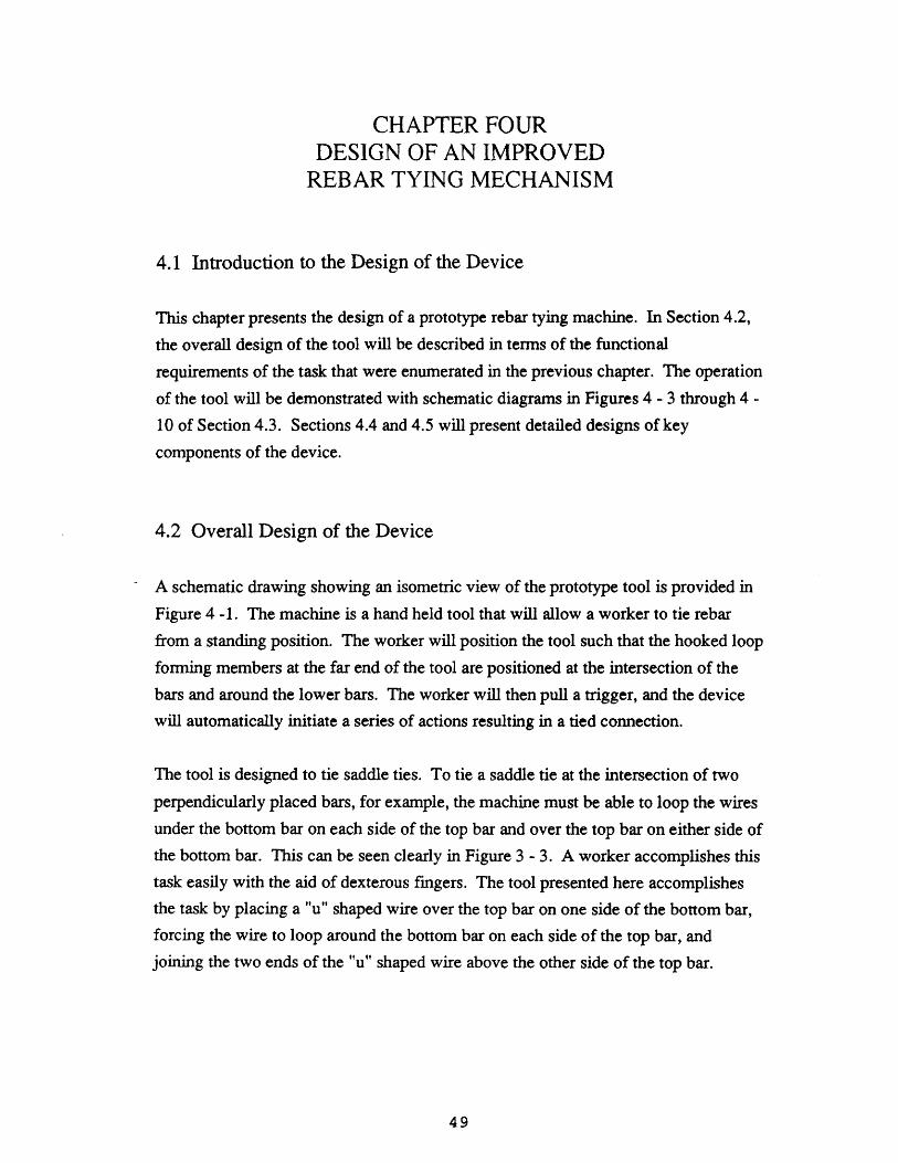
CHAPTER FOURDESIGN OF AN IMPROVED
REBAR TYING MECHANISM
4.1 Introduction to the Design of the Device
This chapter presents the design of a prototype rebar tying machine. In Section 4.2,
the overall design of the tool will be described in terms of the functional
requirements of the task that were enumerated in the previous chapter. The operation
of the tool will be demonstrated with schematic diagrams in Figures 4 - 3 through 4 -
10 of Section 4.3. Sections 4.4 and 4.5 will present detailed designs of key
components of the device.
4.2 Overall Design of the Device
A schematic drawing showing an isometric view of the prototype tool is provided in
Figure 4 -1. The machine is a hand held tool that will allow a worker to tie rebar
from a standing position. The worker will position the tool such that the hooked loop
forming members at the far end of the tool are positioned at the intersection of thebars and around the lower bars. The worker will then pull a trigger, and the device
will automatically initiate a series of actions resulting in a tied connection.
The tool is designed to tie saddle ties. To tie a saddle tie at the intersection of two
perpendicularly placed bars, for example, the machine must be able to loop the wiresunder the bottom bar on each side of the top bar and over the top bar on either side ofthe bottom bar. This can be seen clearly in Figure 3 -3. A worker accomplishes thistask easily with the aid of dexterous fingers. The tool presented here accomplishesthe task by placing a "u" shaped wire over the top bar on one side of the bottom bar,forcing the wire to loop around the bottom bar on each side of the top bar, andjoining the two ends of the "u" shaped wire above the other side of the top bar.

Figure
Prototype Rebcar Tying
Feednism
StapteQueue
Loop
S
50
- 1
Tool
I-

The major components of the device, labelled in Figure 4 - 1, are the staple feed
mechanism and the retractable wire tensioning and twisting mechanism. For the
purpose of this discussion, the top bar will be defined as the bar that is closer to the
tool, with the bottom bar referring to the bar that is farther from the tool. The "u"
shaped wire will be referred to as a tie, a staple, or a staple tie.
The staple feed mechanism acts to push a tie from the staple queue, which is angled
away from the end of the tool to provide maximum clearance from interference at the
end of the tool. The tie loops over the top bar on one side of the bottom bar. The
ends of the tie are forced through the two hooked loop forming members which force
them to bend around the bottom bar on each side of the top bar. The cylindrically
shaped retractable wire tensioning and twisting mechanism then secures the ends of
the tie and joins them on the other side of the top bar by twisting them together. The
operation of the tool is provided in more detail later in the chapter.
4.2.1 Type of Tie / Configuration of Bars
Since the tool is designed to produce saddle ties, it can be used to tie bars configured
like Type A, B, D, and E of Figure 3-2, but not like Type C. Three factors led to the
choice of the saddle tie. The saddle tie is a good choice of tie because of its
applicability to a wide range of configurations of bars. Also, the bars are less likely
to move when tied with a saddle tie than with a diagonal tie, resulting in a higher
quality connection. Finally, since the connection is higher quality, a lower
percentage of connections may need to be tied, resulting in a reduction in the amount
of work required and a proportional reduction in cost.
In light of the above advantages, it is surprising that none of the previously patented
devices have attempted to create saddle ties, especially since the saddle tie has many
of the same design considerations as a diagonal tie. For example, it is necessary in
both cases to form a loop of the wire around the bars. In both cases it is also
necessary to grab the ends of the wires to twist them. However, the saddle tie does
require some additional considerations. For example, the problem of interference isgreater, since two loops must be formed around the bars simultaneously.

Figure 4
Prototype Stapte
1' Diameter
Tie Geometry
11.625'
I7"
Ties
52
I
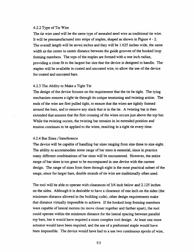
4.2.2 Type of Tie Wire
The tie wire used will be the same type of annealed steel wire as traditional tie wire.
It will be premanufactured into strips of staples, shaped as shown in Figure 4 - 2.
The overall length will be seven inches and they will be 1.625 inches wide, the same
width as the center to center distance between the guide grooves of the hooked loop
forming members. The tops of the staples are formed with a one inch radius,
providing a close fit to the largest bar size that the device is designed to handle. The
staples will be available in coated and uncoated wire, to allow the use of the device
for coated and uncoated bars.
4.2.3 The Ability to Make a Tight Tie
The design of the device focuses on the requirement that the tie be tight. The tying
mechanism ensures a tight tie through its unique tensioning and twisting action. The
ends of the wire are first pulled tight, to ensure that the wires are tightly formed
around the bars, and to remove any slack that is in the tie. A twisting bar is then
extended that ensures that the first crossing of the wires occurs just above the top bar.
While the twisting occurs, the twisting bar remains in its extended position and
tension continues to be applied to the wires, resulting in a tight tie every time.
4.2.4 Bar Sizes / Interference
The device will be capable of handling bar sizes ranging from size three to size eight.
The ability to accommodate some range of bar sizes is essential, since in practice
many different combinations of bar sizes will be encountered. However, the entire
range of bar sizes is too great to be encompassed in one device with the current
design. The range of sizes from three through eight is the most practical subset of the
range, since for larger bars, double strands of tie wire are traditionally often used.
The tool will be able to operate with clearances of 3/4 inch below and 2.125 inches
on the sides. Although it is desirable to have a clearance of one inch on the sides (the
minimum distance allowed in the building code), other design requirements make
that distance virtually impossible to achieve. If the hooked loop forming members
were capable of lateral motion (to move closer together and farther apart), the tool
could operate within the minimum distance for the lateral spacing between parallel
top bars, but it would have required a more complex tool design. At least one more
actuator would have been required, and the use of a preformed staple would have
been impossible. The device would have had to a use two continuous spools of wire,

requiring that both sides of the saddle be tied and requiring the addition of a wire
cutting mechanism. Since the hooked loop forming members have a diameter greater
than the minimum distance, it would be impossible to operate perpendicular to the
top bars within the minimum distance without either using flexible loop forming
members or an unguided loop former. Both methods would have reduced reliability
and made the task of avoiding interference from below more difficult and
unpredictable.
4.2.5 Operation While Standing, Durability and Speed
Standing operation, durability, and speed are the remaining design requirements of
the device. The device is specifically designed to be used from a standing position,
with an adjustable handle enabling comfortable use by workers of different heights.
The cycle time of the tying operation, from initial triggering to return to ready
position, is two seconds. All actuators will be designed to achieve the necessary
accelerations. The device will be capable of surviving the harsh construction
environment, with most of the mechanisms enclosed within the device.
4.3 Operation of the Device
The complete step by step description of how the worker uses the device to
accomplish the task will be illustrated now with several schematic diagrams. The
operation of the two major components of the dtesign, the staple feeding mechanism
and the retractable wire tensioning and twisting mechanism, will be described in the
context of the eight steps which compose the tying operation, shown graphically in
Figures 4 - 3 through 4 - 10.

4.3.1 Step One - Positioning
The first step in the tying operation is performed by the worker, as shown in Figure
4 - 3. The worker must position the device so that the hooked loop forming members
are below the lower bar. This will typically entail the lowering of the device while
the two hooked loop forming members straddle the top bar and are between the rows
of bottom bars, as shown in the first two frames of figure 4 - 3. The third frame ofFigure 4 - 3 shows how the loop forming members are then translated in the directionof the open side of the loop. Once the hooked loop forming members are beneath thelower bar, the worker then lifts up the device, positioning the lower bar firmly in theloop forming members, as in the fourth frame of Figure 4 - 3.
When the minimum interference below the bars is encountered, the worker can rotatethe device into position, so that the hooked loop forming members can pass beneaththe device while avoiding the interference. Now that the device is positioned, theworker must simply press the start button to actuate the series of tying steps.
Figure 4 - 3Step One - Positioning
Frame 1 Frame 2
* * * p•
-.
Frame 3 Frame 4

4.3.2 Step Two - Lowering of Tensioning and Twisting Mechanism
Step two of the tying operation is the lowering of the retractable wire tensioning and
twisting mechanism. This mechanism is originally in the fully retracted position, so
it does not interfere with the positioning operation. The cylindrical member is
lowered into the fully extended position, placing it in contact with the hooked loop
forming members. The bottom of the member contains two wire receiving holes
which are needed to guide the ends of the staple tie into the wire holding mechanism.
These holes are aligned with the grooves of the hooked loop forming members when
the tensioning and twisting mechanism is in the extended position. The tensioning
and twisting mechanism is now in position to receive the ends of the staple.
Simultaneously, the retractable twisting bar is lowered until it contacts the topreinforcing bar. The twisting bar consists of a cylindrical tube coaxial with and
centered on the retractable tensioning and twisting mechanism. Perpendicular to the
tube at the end is a bar which has the function of forcing the wires to cross at the
surface of the top bar when they are twisted.
Figure 4 - 4
Step Two - Lower Twisting Mechanism

4.3.3 Step Three - Staple Feeding
The feeding mechanism consists of a linear pneumatic actuator and a feeding member
that is shaped to conform to the shape of the top of the staple tie. The actuator forces
the feeding member downward, pushing the first wire staple in the queue downward
through guide grooves and through the two grooves in the hooked loop forming
members. The semi-circular loop forming members permanently deform the wires,
forcing them to curve around the bars. Since the wires are permanently deformed,
the ends continue to move in a circular path into the receiving holes of the wire
holding mechanism. Once the ends of the staple have proceeded through the loop
and into the wire holding mechanism, the feeding mechanism stops.
Figure 4 - 5
Step Three - Staple Feeding

4.3.4 Step Four - Grabbing the Ends of the Wire
The ends of the wire are now in position to be held tightly. The wire holding
mechanism contains two pneumatically powered rods which are moved axially within
guide holes. Each rod presses an end of the wire tie tightly into the wire holding
mechanism, deforming the wire around the wire holding anvils and thus firmly
gripping the ends of the wires.
Figure 4 - 6
Step Four - Secure Ends of Staple
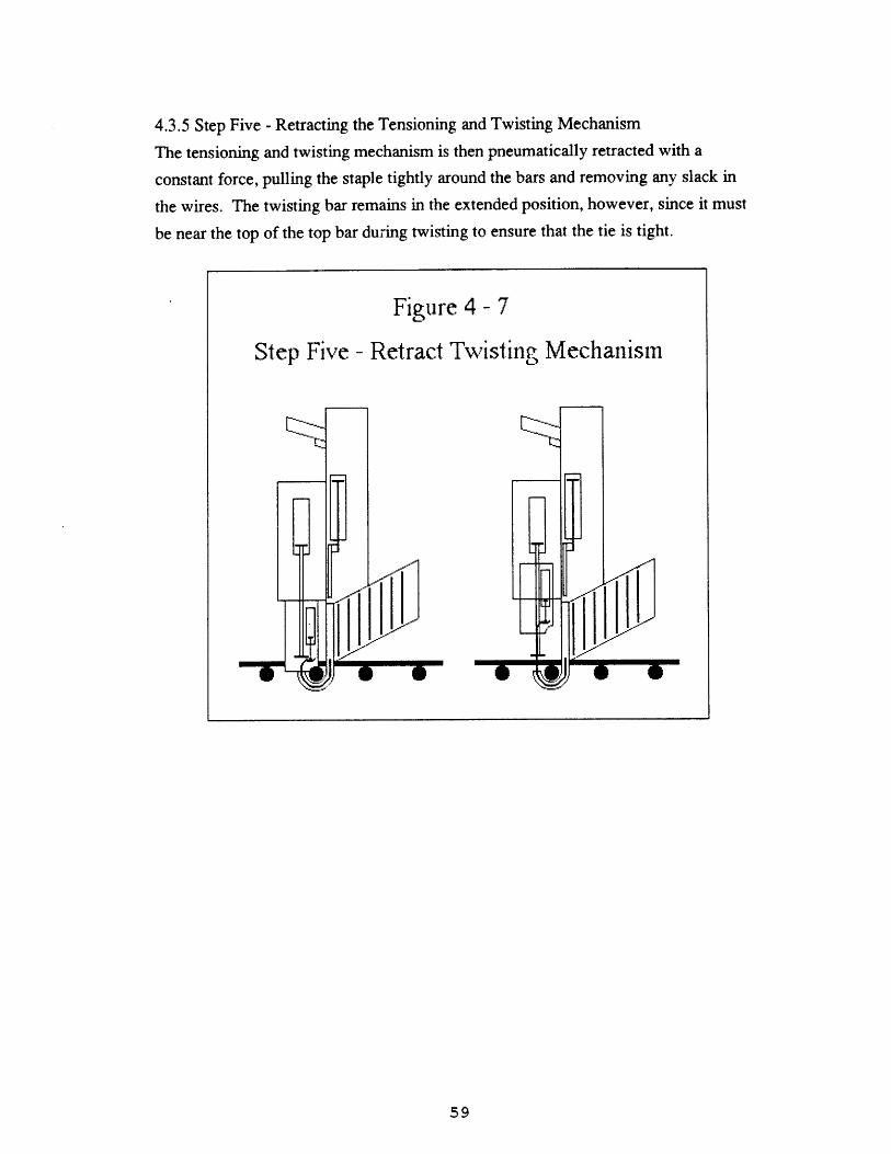
4.3.5 Step Five - Retracting the Tensioning and Twisting Mechanism
The tensioning and twisting mechanism is then pneumatically retracted with a
constant force, pulling the staple tightly around the bars and removing any slack in
the wires. The twisting bar remains in the extended position, however, since it must
be near the top of the top bar during twisting to ensure that the tie is tight.
Figure 4 - 7
Step Five - Retract Twisting Mechanism

4.3.6 Step Six - Twisting the Wire Tie
When the wires have been pulled tight, the tensioning and twisting mechanism is then
rotated a predetermined number of times by a pneumatic rotary actuator, twisting the
ends of the wires together. During the twisting operation, the tensioning and twisting
mechanism continues to be forcibly retracted, keeping tension on the wires. Since it
is retracted with a constant force, the twisting and tying mechanism will move
downward slightly as the free length of the wire shortens from the twisting operation.
The deployed twisting bar ensures that the first crossing of the wires occurs at the top
of the top reinforcing bar. The twisting bar must rotate with the tensioning and
twisting mechanism. If only the twisting bar rotated, the wire would be twisted in
opposite directions on each side of the twisting bar. If the twisting bar remained
stationary, the wire would be twisted above the twisting bar.
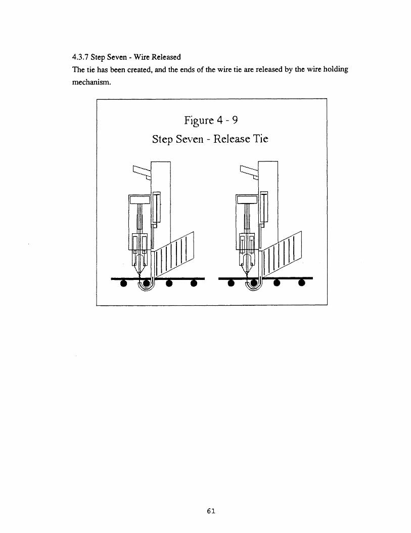
4.3.7 Step Seven - Wire Released
The tie has been created, and the ends of the wire tie are released by the wire holding
mechanism.
Figure 4 - 9
Step Seven - Release Tie

4.3.8 Step Eight - Full Retraction and Reset
Once the ends of the wire are released, the tensioning force causes the twisting and
tying mechanism to fully retract. In addition, the twisting bar is also retracted. The
twisting mechanism, the feeding mechanism, and the trigger mechanism are all reset.
The device is now ready to begin the tying operation again.
4.3.9 Step Nine - Remove Device
The final step is performed by the worker and is the reverse of step one. The workersimply removes the device from around the bars, and is ready to tie the nextconnection.
Figure 4 - 10
Step Eight - Retraction and Reset
4.4 Detailed Design of the Wire Feeding and Loop Forming Mechanism
The detailed design of components of the tool follow in the next two sections.
Design drawings are provided in Appendices 4 and 5 rather than in the text.
Appendix 4 contains an assembly drawing of the cross section through the centerline
of the tool, showing the spatial relationships between key components of the device.
Appendix 5 contains various parts drawings. While reading the following sections,the reader may want to refer to the appendices and to the schematic diagrams
provided previously in the chapter.
The wire feeding and loop forming mechanism is responsible for transferring a staple
tie from its position in the queue to a position where the wire tensioning and twisting
mechanism can secure the ends of the staple and complete the tying operation. The
mechanism consists of a staple queue, a pneumatic actuating mechanism, and a pair
of hooked loop forming members.
The staple queue contains the supply of staple ties. The queue is angled upward to
prevent possible interference near the work surface. The strip of staples is
correspondingly angled, as shown in Figure 4 - 2, with each successive staple offset
slightly upward. The queue contains a spring mechanism which maintains the strip
of staples in the forward most position in the queue. The spring mechanism is very
much like the corresponding mechanism in a common stapler.
The pneumatically actuated feeding mechanism also acts very much like a common
stapler, with the pneumatic actuator driving a formed member which forces the first
staple in the queue to become dislodged from the stack. The pneumatic actuator will
be single acting with a spring return and will have a stroke of 5.5 inches. The end of
the formed member which contacts the staple is shaped to conform to the top of the
staple tie. The other end connects to the actuator.
The formed member forces the staple tie downward to the hooked loop forming
members which contain grooves to guide the ends of the tie. The loop forming
members have a semi-circular shape with an inside diameter of 1.125 inches, to easily
accept a size eight reinforcing bar. The ends of the tie are forced to bend around the
bottom reinforcing bar. This step permanently deforms the wires, thus causing the

wires to continue in a circular motion, with a curvature slightly less than that of the
hooks' grooves, since the wire will rebound slightly when released.
4.5 Detailed Design of the Wire Tensioning and Twisting Mechanism
The wire tensioning and twisting mechanism, having been extended, contains wire
receiving holes which are aligned with the grooves of the hooked loop forming
members. The ends of the staple therefore continue in their circular trajectory into
the receiving holes and into position for the wire holding mechanism.
The wire tensioning and twisting mechanism is cylindrical in shape, with an outside
diameter of 2.5 inches. The majority of the cylinder is hollow, but the two inches at
the end of the cylinder, which contains the wire holding mechanism, is solid to
provide durability.
The wire holding mechanism is an integral part of the tensioning and twisting
mechanism. It consists of the wire receiving holes, a single-acting, spring-returned
pneumatic linear actuator, and two rods that are capable of axial motion. The
pneumatic actuator, which has a 0.5 inch stroke, forces the 0.25 inch diameter rods
through the two guide holes which are each aligned with the planes containing the
two stages of the receiving holes. The end of the wire, having passed into the second
stage of the receiving hole, is pinched between the rod and the bottom of the
receiving hole, which acts as the wire holding anvil.
The twisting bar mechanism lies along the axis of and is connected to the tensioning
and twisting mechanism cylinder. It consists of the twisting bar, an extension tube,
and a single-acting, spring-returned, non-rotating pneumatic actuator with a 5.5 inch
stroke. The twisting bar is attached to the end of the extension tube, which travels
through and is guided by a hole through the end of the tensioning and twisting
cylinder. The other end of the extension tube is secured to the actuator. The twisting
bar moves with the actuator in the axial direction, but rotation is restrained since the
actuator is non-rotating.
The solid end of the tensioning and twisting cylinder is machined to allow the end of
the cylinder to fit over the reinforcing bars. Thus the cylinder can fully extend to
place the end in contact with the hooked loop forming members. The upper end of
the cylinder is fixed to a double-acting, double-ended, linear pneumatic actuator with
a 5.5 inch stroke. The actuator extends and retracts the entire tensioning and twisting
cylinder.
The upper end of the rod of the double-ended cylinder attaches to a toothed gear.
The gear is free to translate axially as the actuator moves, but rotation is controlled
by the cylindrical, co-axial, grooved gear which meshes with the toothed gear. The
rotation is imparted to the grooved gear via a pneumatic rotary actuator and
connected gearing. As the rotary actuator turns, a connected gear drives a chain
which in turn drives the grooved gear.
CHAPTER 5CONCLUSIONS AND RECOMMENDATIONS
5.1 Summary of Work
This thesis has presented an innovative technology in concrete construction: semi-
automated rebar tying. The major contribution of the project is a design for a hand
held, pneumatically powered rebar tying tool.
Chapter 1 explained the motivation of the project and presented some of the potential
impacts of the tool. A major impact of the tool is to relieve the worker from the
grueling aspect of the tying task, bending over for long periods of time. The
economics of rebar tying was discussed, concluding that the use of the tool could
potentially result in cost savings to the concrete construction industry of three
hundred million dollars per year. An additional motivation for the development of an
automated rebar tying tool is the eventual integration of the tool into a fully
automated system for fabrication of reinforcing steel.
Technological developments in concrete construction were characterized. A snapshot
of the state-of-the-art in concrete construction was presented together with a history
of key steps in the development of the technologies. Concrete technologies are
shown to be shifting away from manual methods toward fully automated operations.
A detailed analysis of the task of rebar tying was performed, enabling a list of
functional requirements for a rebar tying tool to be developed. A patent search was
conducted, and eleven patented devices were studied in depth. The lack of success of
the patented devices was explained as a failure to meet all functional requirements of
the task.
The functional requirements led to the design of the improved tying tool. The
operation of the tool was explained graphically with a series of schematic diagrams.
Detailed designs of key components of the tool were presented and explained, with
design drawings being included in Appendices 4 and 5.

Several key prototype components of the device have been fabricated and tested
throughout the design process, to ensure that the components would work as
expected. Two hooked loop forming members were fabricated to make sure that the
wires could be pushed around the reinforcing bars. The solid end of the retractable
wire tensioning and twisting cylinder was fabricated to insure that the trajectory of
the ends of the wires would position them correctly within the wire receiving holes.
Although the fabricated parts worked satisfactorily, the parts have not been
assembled and the pneumatic actuators have not been incorporated into the prototype.
5.2 Suggestions for Further Work
The next step in the development of this tool is the construction of a complete
prototype. The tool must be built to prove that the design satisfactorily performs the
task. Once the prototype is operational, it should immediately be tested in the field.
Valuable feedback can be gained from workers, which will undoubtedly lead to
revisions in the design.
For total process automation to be achieved, rebar tying must be automated. There
has been a substantial amount of research and development of the complimentary
technologies for fully automated reinforcing operations. For example, automated
rebar bending, fabrication, and placement have all been attempted and have achieved
various degrees of success and use.
Once the design of the tool has been tested in the field and all "bugs" and
inefficiencies have been corrected, work should be done to integrate the tool with
some of the complimentary technologies for rebar fabrication.
Automated rebar tying is a key developing technology in the concrete constructionindustry. It is sure to change how concrete construction is performed. In addition toproviding another step toward total automation in the evolution of concreteconstruction, automated rebar tying will allow complimentary technologies forreinforcing steel fabrication to be integrated into a fully automated system.

Appendix 1 - Portland Cement Varieties
Type I - normal
Type IA - normal, air-entrained
Type II - moderate sulfate resistance
Type IIA - moderate sulfate resistance, air-entrained
Type II - high early strength
Type IIIA - high early strength, air-entrained
Type IV - low heat of hydration
Type V - sulfate resistant
White portland cement
Colored portland cement
Oil well cement
Waterproofed cement
Plastic cements
Pipe cement
Block cement
Expansive cements
Epoxy cements
Masonry cement
Type IP - Pozzolanic cement
Type IPA - Pozzolanic cement, air entrained
High alumina
Type N - natural cement
Type NA - natural cement, air entrained
Type S - slag cement
Type SA - slag cement, air entrained

Appendix 2 - Admixtures
Air entraining Admixture - Increases Freeze/Thaw Durability
Water-Reducing Admixture - Reduce Required Mixing Water For a Given Slump
Retarding Admixture - Increases Setting Time
Accelerating Admixture - Decreases Setting Time
Pozzolans - Reduce Internal Temperature During Curing, Reduce Expansion Caused
by Alkali Reactive Aggregates (ASR), Others
Silica Fume - Increased Strength, Decreased Chloride Permeability
Workability Agents - Provide Increased Workability
Superplasticizers - Increased Slump, Greatly Increased Workability, Increased
Flowability and Pumpability, Decreased Required Mixing Water
Dampproofers - Reduce Permeability of Cured Concrete
Bonding Admixtures - Increase Bond Between Fresh Concrete and Existing Cured
Concrete
Latex - Reduced Permeability, Increased Strength, Reduce Cracking
Coloring Admixtures - Create Colored Concrete
Corrosion Inhibiting Admixtures - Inhibit Corrosion of Reinforcing Steel
Appendix 3 - Patented Tying Devices
U.S. Patent 3,494,385 Tieing or Wire Twisting ToolInventor: Thomas J. HaniganIssued: February 10, 1970
U.S. Patent 3,590,885 Tool For Tying WireInventor: James E. WardIssued: July 6, 1971
U.S. Patent 3,593,759 Wire Tying ToolInventor: Norman L. WoogeIssued: July 20, 1971
U.S. Patent 4,177,842Inventor: Gerald G. DilleyIssued: December, 11, 1979
U.S. Patent 4,354,535 Hand-Held Automatic Wire Binding ToolInventors: Robert Y. Powell and Jeff A. FisherIssued: October 19, 1982
U.S. Patent 4,362,192 Wire Tying Power ToolInventors: Donn B. Furlong and Marvin M. MayIssued: December 7, 1982
U.S. Patent 4,653,548 Tool For Tying Crossing ElementsInventor: Antonio Lucas HuertaIssued: March 31, 1987
U.S. Patent 4,685,493 Reinforcing Bar Binding DeviceInventor: Sadao YuguchiIssued: August 11, 1987
U.S.Patent 4,789,010 Apparatus For Manufacturing ReinforcementsInventors: Wolfgang Reymann and Wilhelm OrthIssued: December 6, 1988
U.S. Patent 4,834,148 Reinforcement Binding MachineInventors: Hiroshi Muguruma, Hiroshi Toyoda, and Takayasu SawanoIssued: May 30, 1989
U.S. Patent 4,865,087 Wire Tying MechanismInventor: Robert E. GeigerIssued: September 12, 1989
70

Appendix
Assembly Drawing
Handle
AdjustableHandle
Trigger
RotaryActuatorforTwistingTie
LinearActuatorforExtendingTwistingBar
/
=CTT~T
RetractableWireTensioningand TwistingMechanism
OirC
X 13
I
V-x
Gearingf For RotaryActuator
LinearActuatorfor
- RetractingTwistingMechanism
LinearAct
- foruator
StapleFeedingM h n
Il .I'1
Ooooý HoLo
StapleQueue
okedop
FormingMembers
71
I a- V_ me V_ 1 9- VIV" - - -
I · ~1
1 I
i1
f%=c I, a
0:ý __z n
I
F[F~wrmrrrrv
A

APPENDIX 5END OF TENSIONING AND TWISTING CYLINDER
THREE ORTHOGRAPHIC VIEWS
SIDETOP
------------- --------------,,
~iL
FRONT

APPENDIX 5END OF TENSIONING AND TWISTING CYLINDER
SECTION VIEW OF WIRE RECEIVING HOLES
Ton
0-- - A -
Section A-A
L
IIIII
1
IIIIII

Bibliography
ACI Manual of Concrete Practice 1989, The American Concrete Institute, Detroit,
Michigan, 1989.
Cohen, Edward and Raymond C. Heun. "100 Years of Concrete Building Construction
in the United States" Concrete International. March, 1979. pp. 38-46.
Design and Control of Concrete Mixtures. Twelfth Edition. Portland Cement
Association, 1979.
Dhir, R. K., and J. G. L. Munday, Editors. Advances in Concrete Slab Technology,
Pergammon Press, New York, 1980.
Dinescu, Tudor, and Constantin Radulescu. Slip Form Techniques, Abacus Press, Kent,
England, 1984.
Fagundo, Fernando E., Editor. State-of-the-Art Computer Applications in Concrete
Technolgy. American Concrete Institute Publication SP- 111, Detroit, Michigan, 1988.
Forming Economical Concrete Buildings. Proceedings of an International Conference.
Portland Cement Association, Skokie, Illinois, 1982.
Harris, F. Modern Construction Equipment and Methods, Longman Scientific &
Technical, Essex, England, 1989
"Memorable Miscellany" Concrete International. October, 1979. pp. 46-62.
Riccouard, M. J., Formwork for Concrete Construction, The Macmillan Press, London,
UK 1982
Straub, Hans. A History of Civil Engineering. The MIT Press, Cambridge,Massachusetts, 1964.
Trevorrow, A., Steel Reinforcement, Construction Press, London and New York, 1984.
74

Waddell, Joseph J., Editor, Concrete Construction Handbook. McGraw-Hill, New York,
1968.
Wilde, Robert E. "75 Years of Progress: The ACI Saga." Concrete International.
October, 1979. pg. 15.
75