fire resistance of innovative and slender concrete filled...
TRANSCRIPT

European ProjectFire Resistance of Innovative and Slender Concrete Filled
Tubular Composite Columns (FRISCC)
Prof Leroy Gardner
Dr Finian McCann
Elliptical section members

OUTLINE
FRISCC - Fire Resistance of Innovative and Slender Concrete Filled Tubular Composite Columns
1. STEEL EHS MEMBERS
INTRODUCTION
STRUCTURAL INVESTIGATIONS
DESIGN RULES
2. CONCRETE-FILLED EHS MEMBERS
INTRODUCTION
TESTING AND SIMULATIONS
DESIGN GUIDANCE
DESIGN EXAMPLE
Elliptical section members

FRISCC
Steel EHS members:
• Recently introduced as hot-finished products in
EN 10210
• Combine merits of CHS and RHS
• Elegant aesthetics (CHS)
• Differing rigidities about principal axes
(RHS)� more suitable for applications in
bending
STEEL EHS MEMBERS - INTRODUCTION
a
a
b b
z
y
FRISCC
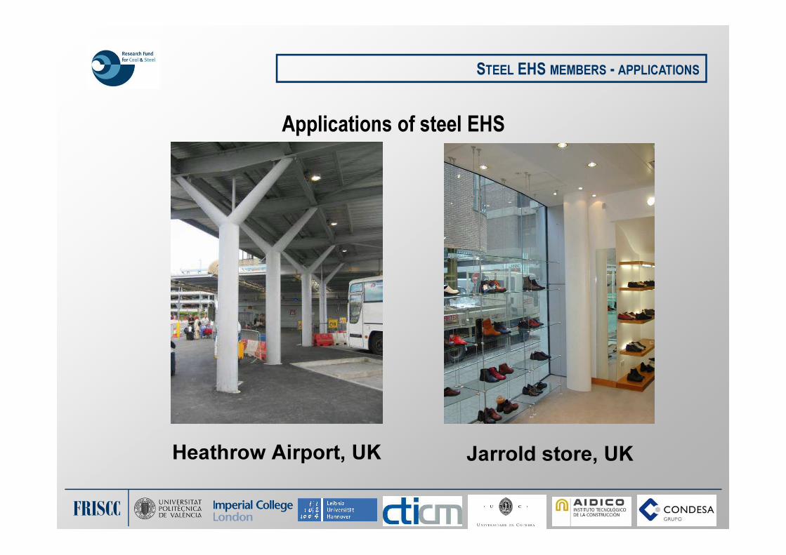
Applications of steel EHS
STEEL EHS MEMBERS - APPLICATIONS
Heathrow Airport, UK Jarrold store, UK
FRISCC
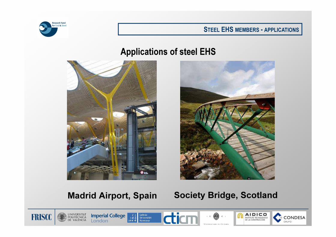
Applications of steel EHS
STEEL EHS MEMBERS - APPLICATIONS
Madrid Airport, Spain Society Bridge, Scotland

FRISCC
Structural scenarios addressed:
1. Local buckling and cross-section classification
2. Shear resistance
3. Combined bending and shear
4. Flexural buckling of columns
STEEL EHS MEMBERS – STRUCTURAL INVESTIGATIONS

FRISCC
Cross-section classification:
STEEL EHS MEMBERS – CROSS-SECTION CLASSIFICATION
b
b
a a
z
y
In compression or minor
axis bending, equivalent
diameter is:
De
= 2rmax
=2a2/b
Elastic critical local buckling – compression and minor axis bending
Initial aim was to determine an equivalent CHS diameter De
rmax)(r
tE
max
cr2
13 ν−
=σ

FRISCC
Cross-section classification:
STEEL EHS MEMBERS – CROSS-SECTION CLASSIFICATION
rmax
is the maximum local
radius of curvature
a
a
b b
rmax
Maximum
compression
Compression
Tension
z
y
Buckling
initiates
De= 0.8a2/b
Elastic critical local buckling – major axis bending

FRISCC
Cross-section classification – Testing:
STEEL EHS MEMBERS – CROSS-SECTION CLASSIFICATION
Material testing of
tensile coupons
Geometric
measurementsCompression
tests
Minor axis bending tests

FRISCC
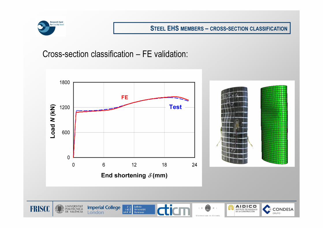
Cross-section classification – Finite element modelling:
STEEL EHS MEMBERS – CROSS-SECTION CLASSIFICATION
• FE models developed in ABAQUS
• Models validated against test results
• Full loading history and failure modes well predicted
• Parametric studies conducted, varying:
• Cross-section slenderness
• Aspect ratios (for all tests, a/b = 2)
FRISCC
Cross-section classification – FE validation:
STEEL EHS MEMBERS – CROSS-SECTION CLASSIFICATION
0
600
1200
1800
0 6 12 18 24
End shortening δ (mm)
Lo
ad
N(k
N)
FE
Test
FRISCC
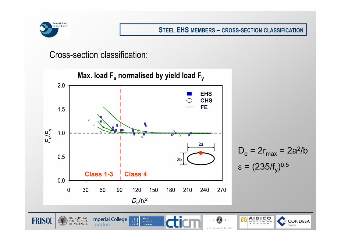
Cross-section classification:
STEEL EHS MEMBERS – CROSS-SECTION CLASSIFICATION
De/tε2
Fu/F
y
0.0
0.5
1.0
1.5
2.0
0 30 60 90 120 150 180 210 240 270
2a
2b
EHS
CHS
FE
Class 1-3 Class 4
De = 2rmax = 2a2/b
ε = (235/fy)0.5
Max. load Fu
normalised by yield load Fy

FRISCC
Cross-section classification:
STEEL EHS MEMBERS – CROSS-SECTION CLASSIFICATION
Minor axis bending – ultimate moment to elastic moment
De/tε2
Mu/M
el
0.0
0.5
1.0
1.5
2.0
2.5
0 20 40 60 80 100 120 140 160 180 200 220 240 260
EHS
CHS
FE
2a
2b
Class 4Class 1-3
De = 2rmax = 2a2/b
ε = (235/fy)0.5

FRISCC
Cross-section classification – summary of measurements of slenderness:
STEEL EHS MEMBERS – CROSS-SECTION CLASSIFICATION
Loading Equivalent diameterCorresponding point on
cross-section
2a
2b
Axial
compressionDe = 2a
2/b
2a
2b
Minor axis
bending (z-z)De = 2a
2/b
2b
2aMajor axis
bending (y-y)
De = 0.8a2/b a/b > 1.36
2b
2a
De = 2b2/a a/b ≤ 1.36
FRISCC
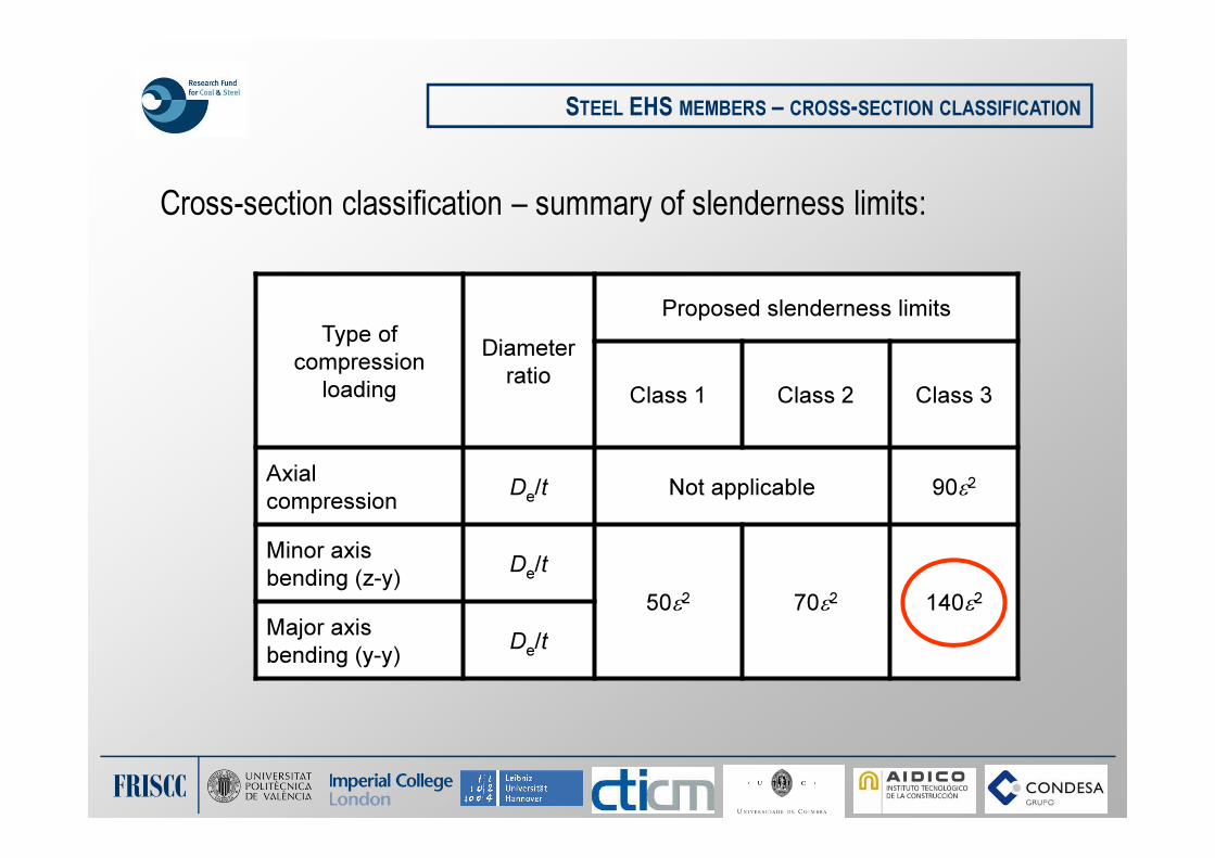
Cross-section classification – summary of slenderness limits:
STEEL EHS MEMBERS – CROSS-SECTION CLASSIFICATION
Type of
compression
loading
Diameter
ratio
Proposed slenderness limits
Class 1 Class 2 Class 3
Axial
compression D
e/t Not applicable 90ε2
Minor axis
bending (z-y)D
e/t
50ε2 70ε2 140ε2
Major axis
bending (y-y)D
e/t
FRISCC
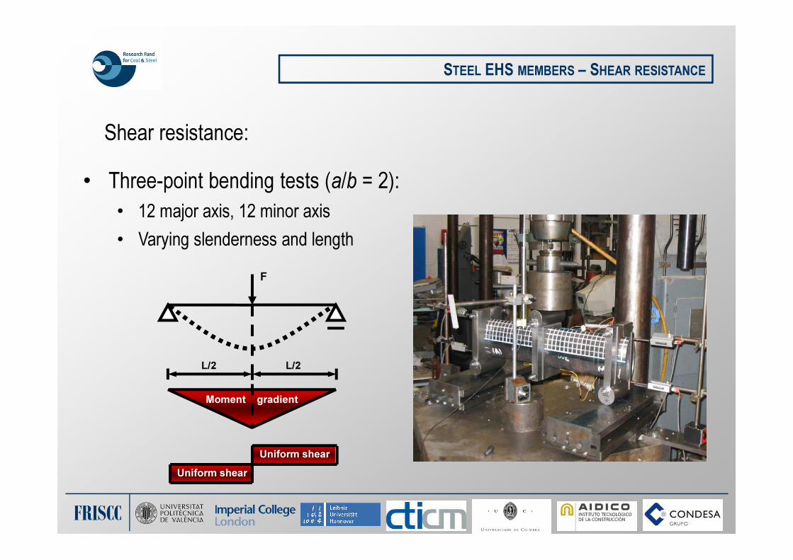
Shear resistance:
STEEL EHS MEMBERS – SHEAR RESISTANCE
• Three-point bending tests (a/b = 2):
• 12 major axis, 12 minor axis
• Varying slenderness and length
L/2 L/2
F
Moment gradient
Uniform shear
Uniform shear

FRISCC
STEEL EHS MEMBERS – SHEAR RESISTANCE
Design plastic shear resistance:
(Av = shear area, fy = yield strength, γM0 = 1.0)
0
,
3/
M
yv
Rdpl
fAV
γ=
b b
a
a
z
y
For shear along z-z:
a a
b
b
z
y
For shear along y-y:
Av = (4b-2t)t A
v = (4a-2t)t

FRISCC
STEEL EHS MEMBERS – SHEAR RESISTANCE
Moment–shear interaction design guidance based on test results:
0.0
0.5
1.0
1.5
0.00 0.25 0.50 0.75 1.00 1.25
Vu/Vpl,Rd
Mu/M
pl,Rd
or M
u/M
el,Rd
Shear along y-y
Shear along z-z
Proposed shear-moment
interaction

FRISCC
Column buckling:
STEEL EHS MEMBERS – COLUMN BUCKLING
• Column tests performed (a/b = 2):
• 12 major axis, 12 minor axis, varying slenderness and length
Knife edge
Load cell
LVDT
Strain gauge
CL
Hydraulic jack

FRISCC
Column buckling – finite element validation:
STEEL EHS MEMBERS – COLUMN BUCKLING
0
250
500
750
0 15 30 45 60
Lateral deflection at mid-height ω (mm)
Lo
ad
N (
kN
)
Test
FE

0.0
0.5
1.0
1.5
0.0 0.4 0.8 1.2 1.6 2.0 2.4 2.8
Member slenderness λ
Buckling about z-z
Buckling about y-yN
u/N
yo
r N
u/N
eff
z
y
EC3 – curve ‘a’
STEEL EHS MEMBERS – COLUMN BUCKLING
Buckling curve ‘a’ can be used for EHS, as for other hot-finished
hollow sections

STEEL EHS MEMBERS – COLUMN BUCKLING
Design guidance:
• Presented proposals are
reflected in the Blue book
• Also in equivalent US
design guidance
• Expected to be
incorporated in future
revisions of EC3
FRISCC
Steel EHS members - conclusions:
STEEL EHS MEMBERS – SUMMARY
• New addition to hot-rolled range
• Significant testing and FE modelling programmes
• Design rules for primary structural configurations
• Incorporation into structural design codes ongoing

FRISCC
Concrete-filled EHS columns:
• Design guidance currently exists for other concrete-filled tubular
columns (CHS, SHS, RHS)
• No current guidance for emerging CFEHS structural solution
• Among aims of FRISCC project: develop guidance on the design
of CFEHS columns
• At room temperature (Imperial College)
• In fire conditions (UP Valencia)
CONCRETE-FILLED EHS MEMBERS - INTRODUCTION

FRISCC
Current guidance:
• Cross-section classification - Eurocode 4: “composite section classified
according to least favourable class of steel elements in compression” (using
Eurocode 3 limits)
• Resistance of compression members: not available for CFEHS
� adopt rules for CHS / RHS?
Strategy for development of design guidance:
• Experimental programme
• Validation of numerical model against experiments
• Numerical parametric study
• Develop design rules for CFEHS columns and beam-columns based on results
CONCRETE-FILLED EHS MEMBERS - INTRODUCTION

FRISCC
Experimental investigation:
• 27 concrete-filled 150×75×6.3 EHS
specimens tested in compression
• Grade S355 steel, grade C30 concrete
• Loading was either concentric or with various
major / minor axis eccentricities
• Specimens with different global slenderness
(lengths) examined
• Some specimens with steel reinforcement
(4No. T10 bars)
CONCRETE-FILLED EHS MEMBERS - EXPERIMENTS

FRISCC
Cross-sectional geometry of experimental specimens:
CONCRETE-FILLED EHS MEMBERS - EXPERIMENTS
a
b
ez
ey
Position of eccentric load
10 mm
18 mm
Specimen buckling about major
axis
Specimen buckling about minor
axis
40 mm
15 mm
T10 reinforcing bar

FRISCC
Testing of columns:
CONCRETE-FILLED EHS MEMBERS - EXPERIMENTS

FRISCC
Numerical modelling:
• Finite element model of CFEHS column developed in ABAQUS
• Steel material model based on tensile testing of coupons
• Concrete damage plasticity model used
CONCRETE-FILLED EHS MEMBERS – NUMERICAL MODELLING
concrete core
steel tube
Buckling axis
end-plate

FRISCC
Validation of numerical model – ultimate loads:
CONCRETE-FILLED EHS MEMBERS – NUMERICAL MODELLING
0
200
400
600
800
1000
1200
1400
0 200 400 600 800 1000 1200
Nu,exp(kN)
Nu,FEA (kN)
Present study
+10%
Unity
-10%
Nu,exp / Nu,FEA: average = 1.12, STDEV = 0.07

FRISCC
Validation of numerical model – load–deflection behaviour:
CONCRETE-FILLED EHS MEMBERS – NUMERICAL MODELLING
0
100
200
300
400
500
600
700
800
0 5 10 15 20 25
Load
(kN
)
Axial displacement (mm)
E20:L2-MA-50-R - test
E20:L2-MA-50-R - FEA
E21:L1-MA-50-R - test
E21:L1-MA-50-R - FEA
E22:L3-MI-25-R - test
E22:L3-MI-25-R - FEA

FRISCC
Validation of numerical model – failure mode:
CONCRETE-FILLED EHS MEMBERS – NUMERICAL MODELLING

FRISCC
Numerical parametric study:
• 360 specimens modelled, varying
• cross-section
• slenderness
• reinforcement ratio
• cover to reinforcement
• load eccentricity (also modelled concentric loading)
• buckling axis
• Results used as basis to formulate design rules
CONCRETE-FILLED EHS MEMBERS – NUMERICAL MODELLING

FRISCC
Design guidance strategy:
• Apply rules for concrete-filled CHS and RHS to CFEHS columns
• Buckling curve relates to EC3 curve for members in axial compression
• Member imperfection used to determine first-order moments for members
in combined compression and uniaxial bending (i.e. eccentrically-loaded)
CONCRETE-FILLED EHS MEMBERS – DESIGN GUIDANCE
FRISCC
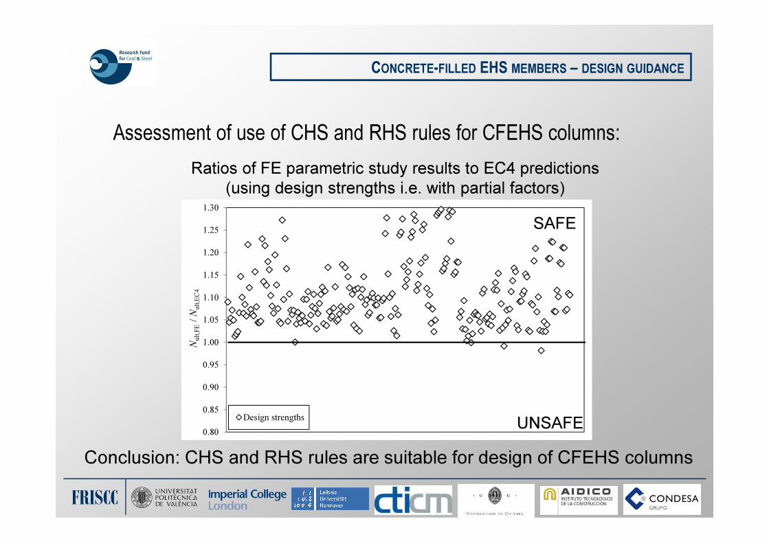
Assessment of use of CHS and RHS rules for CFEHS columns:
CONCRETE-FILLED EHS MEMBERS – DESIGN GUIDANCE
Ratios of FE parametric study results to EC4 predictions
(using design strengths i.e. with partial factors)
Conclusion: CHS and RHS rules are suitable for design of CFEHS columns
0.80
0.85
0.90
0.95
1.00
1.05
1.10
1.15
1.20
1.25
1.30
Nult,FE
/ N
ult,EC4
Design strengths
SAFE
UNSAFE

FRISCC
Design example: determine capacity of concentrically-loaded CFEHS
Column is 400 × 200 × 12.5 EHS, L = 4 m, B.C. = P-P
2a = 400 mm, 2b = 200 mm, t = 12.5 mm
fcd = 30 MPa, fyd = 355 MPa, Ea = 210 GPa, Ecm = 36 GPa
Cross-sectional properties of concrete element:
Ac =
= 515 cm2
Ic,z=
= 9865 cm4
Cross-sectional properties of steel element:
As = 113 cm2
, Is,z = 5843 cm4 (from Tata section tables)
CONCRETE-FILLED EHS MEMBERS – DESIGN EXAMPLE
400 mm
200 mm
12.5 mm
( ) ( ) ( )( )5.1222005.1224004
22224
×−×−=−−
ππ
tb ta
( ) ( ) ( )( )335.1222005.122400
642222
64×−×−=−−
ππ
tb ta

FRISCC
Design example: determine capacity of concentrically-loaded CFEHS
Plastic resistance to compression:
Npl,Rd = Aa fyd + Ac fyc = (113)(355)+(515)(30) = 5557 kN
Effective minor axis flexural rigidity:
(EI)eff,z = EaIa,z + 0.6 EcmIc,z= (210000)(5843)+(36000)(9865)
= 13790 kN m2
Elastic critical load for buckling about minor axis:
Ncr,z = π2(EI)eff,z / L
2 = π2(13790) / 42 = 8506 kN
CONCRETE-FILLED EHS MEMBERS – DESIGN EXAMPLE
400 mm
200 mm
12.5 mm

FRISCC
Design example: determine capacity of concentrically-loaded CFEHS
Nondimensional slenderness:
Reinforcement ratio ρ = 0, therefore use buckling curve a:
� Imperfection factor α = 0.21
CONCRETE-FILLED EHS MEMBERS – DESIGN EXAMPLE
82.08508
5676
cr,z
Rdpl,===
N
Nλ
( )( ) ( )( ) 898.082.021.082.021.015.015.02
2
o =+−+=+−+=Φ λλλα
( ) 786.0850.0898.0898.0/1/122
22 =−+=
−Φ+Φ= λχ
kN44616526767.0Rdpl,Rdb, =×== NN χ

FRISCC
Thank you!
CONCRETE-FILLED EHS MEMBERS – DESIGN EXAMPLE