an innovative solution to teaching the principle of … id #13790 an innovative solution to teaching...
TRANSCRIPT

Paper ID #13790
An Innovative Solution to Teaching the Principle of Virtual Work
Mrs. Heather Annette Sustersic, The Pennsylvania State University
Heather Sustersic, P.E., is a Research Associate in the Architectural Engineering Department at The Penn-sylvania State University. She teaches senior-level structural engineering analysis and design courses inaddition to advising students in their senior thesis projects and conducting scientific research in designingbuildings for tornado resistance.
Mrs. Sustersic is passionate about increasing student engagement and encouraging deep understandingto develop in her students. She incorporates a variety of demonstration materials (both traditional andnon-traditional) and interactive activities into her lecture-based delivery format.
Caroline June Klatman, The Pennsylvania State University
Caroline Klatman is a teaching intern within The Architectural Engineering Department at The Pennsyl-vania State University. Under the advisement of Professor Heather Sustersic, she assists in enhancingcourse material. Her responsibilities often include revising lecture content, incorporating code updatesinto class material, aiding students in understanding course concepts, and creating homework assign-ments and solutions. Ms. Klatman is able to use her personal experience as a student to offer practicaladvice into effective educational strategies.
In May, 2015, Ms. Klatman will graduate with integrated Bachelor of Architectural Engineering/Masterof Architectural Engineering degrees.
c©American Society for Engineering Education, 2015
Page 26.190.1

An Innovative Solution to Teaching the Principle of Virtual Work
Figure 1: Truss model used for virtual work interactive class demonstration (16" wide x 8" tall).
Each truss member is capable of +/- 1” of elongation. The left support is idealized as a pin; the
right support as a roller.
Introduction
Providing a balance of abstract theory and concrete practical application, in a manner that
encourages active learning when teaching structural engineering courses, is an ongoing challenge
for educators1,2. Student learning styles and attitudes toward their education vary considerably,
even within a small group of individuals. While procedural learners rely on memorization of
facts and a surface understanding of the concepts, other learners are interested in a deeper
understanding and being able to provide context to the material3. Each type of learner has
different needs which must be addressed when delivering course content. Adding further
complexity to this issue, even the most passionate student has difficulty focusing for the full
duration of a 75 minute lecture. Focus problems are exacerbated by general fatigue experienced
by students enrolled in rigorous engineering programs, where there are high expectations for
student work completed outside of instructional contact hours. Educators must thus be vigilant
in monitoring the level of interest they engender in their students during lectures4.
One solution as to how to maintain interest is to develop demonstrations to accompany
traditional lecture materials, thereby encouraging students to interact and engage in hands-on
learning. Hong5 noticed that many structural engineering students are too focused on “problem-
solving procedure[s]” with limited attention to developing true understanding. In response,
Hong proposes active learning techniques with emphasis on “visual thinking” instead of
“mathematical thinking” be employed in the classroom. Student response to this approach has
been very positive. Prince10 further demonstrates the benefits of active learning. Improvement
in student performance is shown through his compilation of prior studies and means of
quantifying the effects of active learning techniques.
Page 26.190.2

Educational truss models are not new to engineering education. Bigoni, et. al.6, developed a
modular 3-dimensional truss model for the purpose of teaching global truss behavior, including
stability issues out of plane. Taylor, et. al.7 used lego pieces and string to teach non-engineering
students the concept of tension-only members in a planar truss. Interactive wood truss models to
demonstrate the concept of zero-force members are shown to be effective for introductory
engineering mechanics classes.8
Many existing truss models have already proven effective in demonstrating various concepts to
students and promoting student engagement, but to the authors’ knowledge, there are no
published studies demonstrating the use of physical truss models to teach the concept of virtual
work. By using a custom-built truss model made of recycled lab materials, this study, conducted
within the Architectural Engineering Department at The Pennsylvania State University, explores
the effectiveness of providing a physical truss demonstration, accompanied by a traditional
presentation, to teach the abstract concept of work-energy methods for determining nodal
deflections in truss structures.
Scope and Objectives
The primary objective of this study was to investigate the effectiveness of incorporating an
inexpensive, interactive, hands-on truss demonstration model to teach work/energy methods for
computing truss deflections and compare and contrast it with a more traditional lecture-example
presentation format. A secondary outcome of the study was the observation that the combination
of presentation styles is both preferable from the student perspective, and effective from an
assessment standpoint.
A group of 24 students, enrolled in the required 400-level indeterminate structural analysis
course, AE 430, were invited to participate in this pilot research study. Twenty-three students
agreed to participate in the survey and were present on the day of the study.
Methodology
Students received a background lecture in work-energy methods for computing deflections the
week before the study began, and were assigned relevant readings in their course textbook to be
completed before attending the study, similar to a flipped classroom. The study began with a
brief presentation of the principle of virtual work for trusses after which students were divided
into two groups, Group A and Group B. Group assignments were posted prior to study
commencement. Mid-term exam #1 grades were used to ensure equal ability levels were present
in each group. Informed consent, under approval of Institutional Review Board (IRB) human
subject research protocol, was obtained for 23 participants.
Group A witnessed a lecture example worked for them in a traditional lecture format. A student
teaching intern provided instruction on a tablet PC for an example truss problem, and led
students in filling out a worksheet with step-by-step guidance.
Group B participated in an interactive demonstration using a custom-fabricated truss model –
further described in the next section - capable of displaying measurable axial member elongation
and shortening (Figure 1-7). Students took turns reading measurements, calculating values, and
loading/unloading the model.
Page 26.190.3

After Group A watched the traditional lecture and Group B viewed the truss demonstration, all
students took a 15 minute timed quiz to evaluate their initial understanding of the material. The
students then switched rooms, viewed the alternate style presentation, and re-took the quiz.
Students were also asked to complete a survey to rank the perceived benefits of each instruction
method.
Finally, a simple truss problem, requiring the use of work-energy methods, was included on the
course final exam. Scores for the quizzes, final exam truss problem, and overall final exam score
were recorded and compared. Survey results were compiled and analyzed.
Description of the Truss Model
Preliminary model configuration, including dimensions, loads, and desired elongation properties
of each axial member, was developed by the author in 2013. Undergraduate students were
recruited to fabricate the truss model, pictured in Figure 1. Under collaborative consultation with
the author, the undergraduate students repurposed existing materials and fabricated selected new
components to meet the design specifications. Each truss member is able to elongate or shorten
– in the axial direction only – through the use of springs placed on either side of the member
mid-point, as shown in Figure 2.
The members are sufficiently stiff to prevent any flexural response in the members when the
truss is loaded at joint locations. Each truss member includes an elongation measurement scale,
as shown in Figure 3, which permits users to make differential elongation measurements at
different stages of loading. Aluminum extension pieces were fabricated to create members of
varying lengths, particularly for the truss diagonals, with epoxy resin used to affix the extension
to the original dashpot pieces.
Figure 2: Close-up
view of spring dashpot
truss axial member
(center vertical
member shown here)
Figure 3: Detail view of
diagonal top chord
member of elongation
measurement scale;
shown in neutral position
Figure 4: Close-up view of right roller
support. An aluminum channel prevents
lateral movement of the roller when the truss is
loaded.
Page 26.190.4
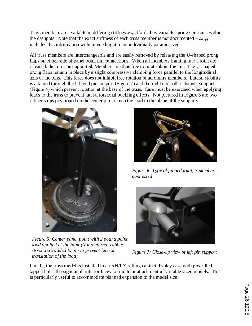
Truss members are available in differing stiffnesses, afforded by variable spring constants within
the dashpots. Note that the exact stiffness of each truss member is not documented – ∆𝐿𝑝𝑖
includes this information without needing it to be individually parametrized.
All truss members are interchangeable and are easily removed by releasing the U-shaped prong
flaps on either side of panel point pin connections. When all members framing into a joint are
released, the pin is unsupported. Members are thus free to rotate about the pin. The U-shaped
prong flaps remain in place by a slight compressive clamping force parallel to the longitudinal
axis of the pins. This force does not inhibit free rotation of adjoining members. Lateral stability
is attained through the left end pin support (Figure 7) and the right end roller channel support
(Figure 4) which prevent rotation at the base of the truss. Care must be exercised when applying
loads to the truss to prevent lateral torsional buckling effects. Not pictured in Figure 5 are two
rubber stops positioned on the center pin to keep the load in the plane of the supports.
Figure 5: Center panel point with 2 pound point
load applied at the joint (Not pictured: rubber
stops were added to pin to prevent lateral
translation of the load)
Figure 6: Typical pinned joint; 3 members
connected
Figure 7: Close-up view of left pin support
Finally, the truss model is installed in an AN/EX rolling cabinet/display case with predrilled
tapped holes throughout all interior faces for modular attachment of variable sized models. This
is particularly useful to accommodate planned expansion to the model size.
Page 26.190.5

Traditional Lesson Plan
An undergraduate student teaching intern led students in a 15 minute traditional step-by-step
worked example on tablet PC. An abbreviated version of the worksheet used by presenter and
students is provided on page 10 in Figure 12 (left). The nomenclature presented is consistent
with the course textbook9.
Problem geometry and member forces for the P system (actual loads) and Q system (virtual
loads) were provided. Students filled in the table provided based on the given information, then
calculated row and column summations to determine the total embodied strain energy in the
truss. Then students inserted values for member area, A, and modulus of elasticity, E, and
solved for truss deflection at the point of virtual load application.
Interactive Lesson Plan
One detached member of the truss was circulated among the students so they could exert axial
compressive and tensile forces on member and experience individual member elongation and
shortening. Then, a brief description of the model joints, geometry, and support conditions was
provided. Students received a blank worksheet (see Figure 12, right, for the full worksheet)
containing a graphical representation of the model truss (Figure 8), governing equations, and a
table for recording member elongations and forces. The goal of the exercise was to determine
the horizontal and vertical displacement at joint B due to a load, P, applied at joint D. Neutral
readings for individual member elongation were noted, so that only the differential elongation
would be considered for the analysis.
Figure 8: Problem statement for truss
model example presentation
Figure 9: Spring scale connected at the top panel
point applies “virtual” load.
Students voted on the magnitude of point load P to be applied in the downward sense at joint D,
ranging between 1 and 3 pounds (Figure 5). With point load P in place, students took turns
reading the axial elongation or shortening, ∆𝐿𝑝𝑖, for each member, using the sign convention that
elongation, caused my member tension, is positive. Point load P was then removed. A volunteer
student next applied a unit load in the positive x direction at joint B (Figure 9), representing a
unit “virtual” load applied in the direction of the desired nodal displacement. Students
performed static truss analysis to determine the resultant force in each member due to the applied
virtual load. With the virtual load in place, another student reapplied the point load P. Then the
Page 26.190.6
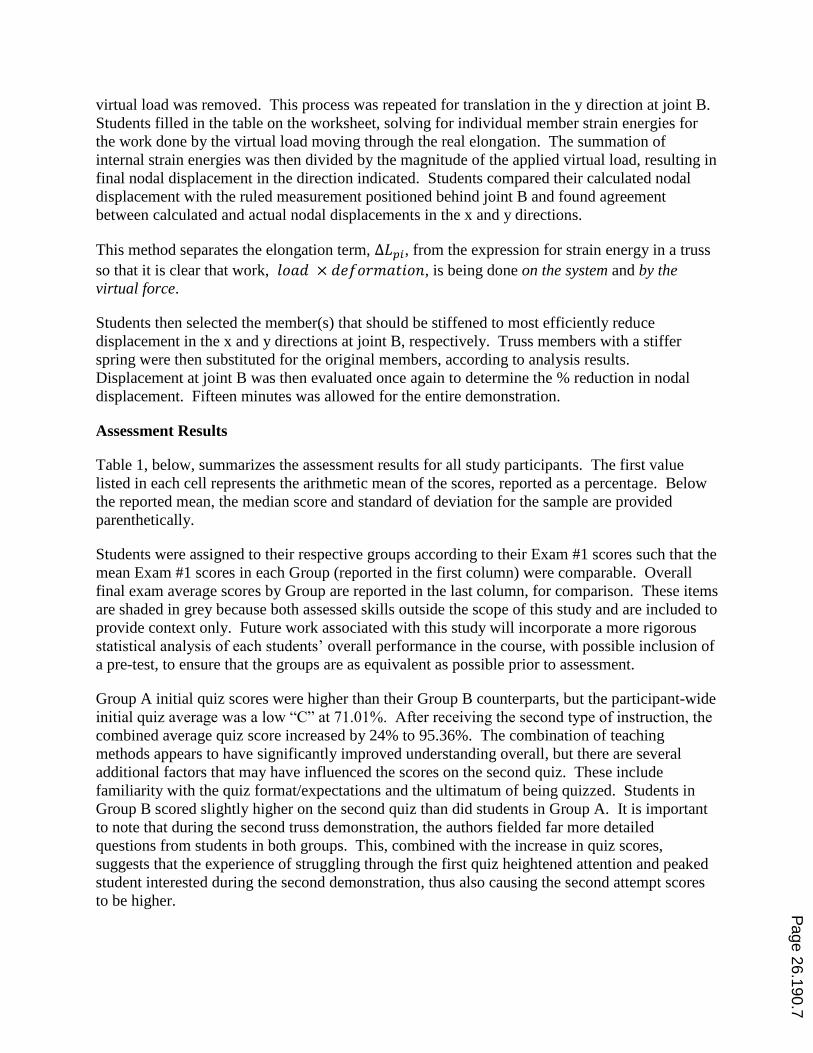
virtual load was removed. This process was repeated for translation in the y direction at joint B.
Students filled in the table on the worksheet, solving for individual member strain energies for
the work done by the virtual load moving through the real elongation. The summation of
internal strain energies was then divided by the magnitude of the applied virtual load, resulting in
final nodal displacement in the direction indicated. Students compared their calculated nodal
displacement with the ruled measurement positioned behind joint B and found agreement
between calculated and actual nodal displacements in the x and y directions.
This method separates the elongation term, ∆𝐿𝑝𝑖, from the expression for strain energy in a truss
so that it is clear that work, 𝑙𝑜𝑎𝑑 × 𝑑𝑒𝑓𝑜𝑟𝑚𝑎𝑡𝑖𝑜𝑛, is being done on the system and by the
virtual force.
Students then selected the member(s) that should be stiffened to most efficiently reduce
displacement in the x and y directions at joint B, respectively. Truss members with a stiffer
spring were then substituted for the original members, according to analysis results.
Displacement at joint B was then evaluated once again to determine the % reduction in nodal
displacement. Fifteen minutes was allowed for the entire demonstration.
Assessment Results
Table 1, below, summarizes the assessment results for all study participants. The first value
listed in each cell represents the arithmetic mean of the scores, reported as a percentage. Below
the reported mean, the median score and standard of deviation for the sample are provided
parenthetically.
Students were assigned to their respective groups according to their Exam #1 scores such that the
mean Exam #1 scores in each Group (reported in the first column) were comparable. Overall
final exam average scores by Group are reported in the last column, for comparison. These items
are shaded in grey because both assessed skills outside the scope of this study and are included to
provide context only. Future work associated with this study will incorporate a more rigorous
statistical analysis of each students’ overall performance in the course, with possible inclusion of
a pre-test, to ensure that the groups are as equivalent as possible prior to assessment.
Group A initial quiz scores were higher than their Group B counterparts, but the participant-wide
initial quiz average was a low “C” at 71.01%. After receiving the second type of instruction, the
combined average quiz score increased by 24% to 95.36%. The combination of teaching
methods appears to have significantly improved understanding overall, but there are several
additional factors that may have influenced the scores on the second quiz. These include
familiarity with the quiz format/expectations and the ultimatum of being quizzed. Students in
Group B scored slightly higher on the second quiz than did students in Group A. It is important
to note that during the second truss demonstration, the authors fielded far more detailed
questions from students in both groups. This, combined with the increase in quiz scores,
suggests that the experience of struggling through the first quiz heightened attention and peaked
student interested during the second demonstration, thus also causing the second attempt scores
to be higher.
Page 26.190.7

Table 1: Assessment Results for Study Participants (n=23); results reported by “Mean (median,
standard of deviation for the sample, σ)”
Group
Assignment Exam #1 Score
Quiz Scores Final Exam Scores
1st Attempt 2nd Attempt Problem #1 Overall
Group A
(control) 77.45%
(80.00%, 11.18) 78.79%
(86.67%, 20.18)
94.55% (93.33%, 5.83)
85.45% (88.00%, 14.56)
76.55% (76.00%, 9.64)
Group B
(trial) 77.00%
(80.00%, 9.13) 63.89%
(66.67%, 21.92) 96.11%
(93.33%, 3.43) 75.00%
(72.00%, 19.08) 80.17%
(80.00%, 8.61)
Combined 77.22% (80.00%, 10.04)
71.01% (66.67%, 21.98)
95.36% (93.33%, 4.69)
80.00% (80.00%, 17.52)
78.43% (78.00%, 9.09)
A final exam for the course was administered approximately 9 weeks after the study was
performed. Problem #1 on the final exam measured student mastery of work/energy methods for
computing truss nodal displacements. Group A students scored one letter grade higher on this
problem than did Group B students. However, Group B students performed better overall on the
final exam than did Group A students. Since both groups received both treatments, however, the
final exam scores do not provide solid evidence that either instructional method is superior. It is
difficult to ethically separate the class into treatment-only and control-only groups to gauge
independent behavior due to sample size and frequency of the course offerings.
Student Evaluation and Surveys
After each presentation-quiz module, students were asked to complete a survey to rate perceived
effectiveness of the presentation that they just viewed. A total of 20 students completed the
surveys; however, 2 surveys were removed from tabulated results due to student failure to clearly
identify presentation format. The survey included 6 questions and one “additional feedback”
section, as shown in Figure 10. The first 4 questions included quick-select Likert scale rating
options ranging from “Strongly Disagree” to “Strongly Agree”. Results from the Likert scale
questions are tabulated in Figure 11, below. The remaining 2 questions on the survey were short
answer response and requested students to comment on what they liked best and least for each
presentation style.
In general, students rated the clarity of the truss demonstration slightly lower than the traditional
example, but rated both methods as effective teaching tools. Both methods were rated as helping
students understand the concept of virtual work for trusses, with slight preference for traditional
methods of instruction.
In the open comment section of the survey, there was a mix of student reviews for the
presentation styles, with equal quantity of negative and positive comments for each. The
majority of students responded positively to the interactive truss model; they felt that this
presentation style was “more engaging,” citing “seeing it actually happen” and “visually
understand[ing] what was going on” as reasons for this. Several students commented that the
truss model helped them “understand a lot better how forces affect truss members” and found
that visually seeing member elongation helped them understand the sign convention and axial
deformation of truss members. However, students indicated that the truss model demonstration
Page 26.190.8

did not prepare them well for the quiz, the format of which more closely aligned with the
traditional example presented. Students commented that this presentation style lacked clarity in
terms of whether virtual work or real work was being evaluated.
In contrast, most students thought that the traditional method was “simple,” “easy,” “clear,” and
“straight-forward.” Some students attributed this distinction to a comfort level developed with
the traditional style of presentation, due to its similarity with other examples provided in this and
previous courses. They also commented on the traditional method’s similarity and direct
applicability to the quiz question, indicating that this method provided more immediately
transferable tools for the assigned quiz problem. However, several students indicated that the
traditional approach was “boring” and “lacked interaction.” There were also several negative
comments regarding the pace of the presentation (too fast) and that force values were given to
them.
Several students recommended combining the two presentations styles into one such that the
truss demonstration matched the traditional worked example. Both presentations were described
as “rushed,” with specific student recommendations to increase the time devoted to each
presentation. Other responses included recommendations for specific changes to handout
materials, clarifying real versus virtual work in the truss demonstration, and more time spent on
theory in an introductory lecture prior to introducing the examples.
Figure 10: Partial Voluntary Survey Response Form for the Study (completed by 18
participants)
Page 26.190.9

Figure 11: Student perception of teaching effectiveness - survey results by question
0
2
4
6
8
10
1) Was the example clear to you?
Traditional Example Truss Demo
0
2
4
6
8
10
2) Did the presentation method help
you understand the concept of
virtual work for trusses?
Traditional Example Truss Demo
0
2
4
6
8
10
3) Would you recommend this style
of presentation to be used in future
course offerings?
Traditional Example Truss Demo
0
2
4
6
8
10
4) Was this presentation method
effective as a teaching tool?
Traditional Example Truss Demo
Page 26.190.10
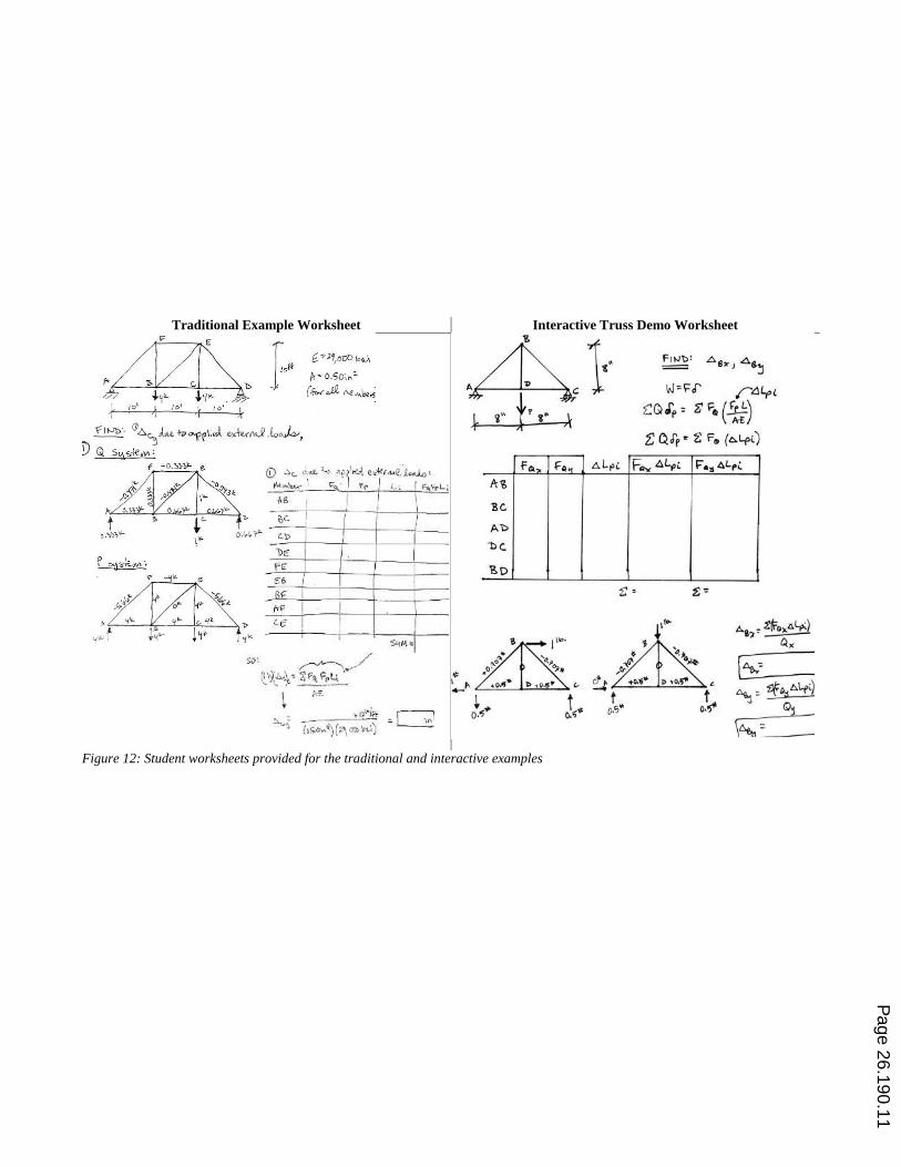
Traditional Example Worksheet Interactive Truss Demo Worksheet
Figure 12: Student worksheets provided for the traditional and interactive examples
Page 26.190.11

Proposed Study Revisions
In response to student feedback and observations from this preliminary study, a continued
evaluation of the effectiveness of the truss demonstration model will be implemented annually,
with data collection to align with the offering of this course. Specific changes that will be made
include:
- Schedule more time for the presentations and assessments.
- Increase the time spent on theory and introductory material provided prior to the
presentations.
- Reserve two immediately adjacent classrooms for the duration of the study so that both
presentations are provided in a controlled environment.
- Restructure the virtual work quiz problems to be neutral of presentation style.
- Make minor edits to handout materials to improve context.
- Fabricate more truss members so that different truss configurations can be modeled.
Additionally, IRB approval will be requested for an expanded study in future course offerings,
allowing for the collection of more data over the course of the full semester to identify trends,
rather than limiting the data acquisition to specific quiz scores.
Conclusion
Two different instructional methods were used to teach the concept of work-energy for
calculating truss nodal displacements. An innovative truss model was used to engage students in
an interactive, hands-on analysis experience, as was traditional teacher-led worked example.
Students were assessed after receiving each treatment, with quiz scores suggesting that it is the
combination of teaching approaches, among other factors, that increases proficiency.
Bibliography
1 Felder, R. M., Woods, D. R., Stice, J. E., & Rugarcia, A. (2000). The Future Of Engineering Education. Chem.
Engr. Education, 26-39. 2 Goodhew, P. J. (2010). Teaching Engineering: All You Need to Know About Engineering Education but were
Afriad to Ask. UK Centre for Materials Education. 3 Felder, R. M., & Brent, R. (2005). Understanding Student Differences. The Journal of Engineering Education, 57-
72. 4 Litzinger, T. A., Lattuca, L. R., Hadgraft, R. G., & Newstetter, W. C. (2011). Engineering Education and the
Development of Expertise. Journal of Engineering Education, 123-150. 5 Hong, Pyoyoon. (2014). Quantitative and Qualitative Understanding in Structural Engineering. 2014 ASEE
Southeast Section Conference.
Page 26.190.12

6 Bigoni, D., Dal Corso, F., Misseroni, D., & Tommasini, M. (2012). A teaching model for truss structures.
European Journal of Physics, 1179-1186. 7 Taylor, J.A., Dana, T. M., & Tasar, M.F. (1999). Bridging Science and Engineering: An Integrated Course for
Non-Science Majors. Summer Meeting of the American Association of Physics Teachers (AAPT), San
Antonio, TX. 8 Welch, R. W. & Klosky, J. L. (2007). An Online Database and User Community for Physical Models in the
Engineering Classroom. ASEE Advances in Engineering Education, 1-25. 9 Leet, K. M., Uang, C-M, & Gilbert, A.M. (2011). Fundamentals of Structural Analysis (Fourth Edition). McGraw-
Hill. 10 Prince, M. (2004). Does Active Learning Work? A Review of the Research. Journal of Engineering Education,
223-231.
Page 26.190.13