an improved semi-analytical solution for stress at round
TRANSCRIPT
HAL Id: hal-02310717https://hal.archives-ouvertes.fr/hal-02310717
Submitted on 5 Nov 2019
HAL is a multi-disciplinary open accessarchive for the deposit and dissemination of sci-entific research documents, whether they are pub-lished or not. The documents may come fromteaching and research institutions in France orabroad, or from public or private research centers.
L’archive ouverte pluridisciplinaire HAL, estdestinée au dépôt et à la diffusion de documentsscientifiques de niveau recherche, publiés ou non,émanant des établissements d’enseignement et derecherche français ou étrangers, des laboratoirespublics ou privés.
An improved semi-analytical solution for stress atround-tip notches
Mingchao Liu, Yixiang Gan, Dorian A.H. Hanaor, Bin Liu, Chang-Qing Chen
To cite this version:Mingchao Liu, Yixiang Gan, Dorian A.H. Hanaor, Bin Liu, Chang-Qing Chen. An improved semi-analytical solution for stress at round-tip notches. Engineering Fracture Mechanics, Elsevier, 2015,149, pp.134-143. �10.1016/j.engfracmech.2015.10.004�. �hal-02310717�
Liu, M., Gan, Y., Hanaor, D. A., Liu, B., & Chen, C. (2015). An improved semi-analytical
solution for stress at round-tip notches. Engineering fracture mechanics, 149, 134-143.
1
An improved semi-analytical solution for stress at round-tip
notches
Mingchao Liu1, 2, Yixiang Gan2, *, Dorian A.H. Hanaor2, Bin Liu1, and Chang-
Qing Chen1, *
1. Department of Engineering Mechanics, CNMM & AML, Tsinghua University, Beijing 100084, China
2. School of Civil Engineering, The University of Sydney, Sydney, NSW 2006, Australia
Abstract
In order to investigate the brittle failure of key-hole-notched components, the stress distribution
at notch tips is studied numerically and theoretically. A semi-analytical formula is developed
for the maximum notch-tip-stress, incorporating crack-tip-blunting, stress-concentration and
stress-equilibrium. Stress distributions in notched plates are simulated by finite-element method
showing improved accuracy of the formula relative to established solutions. Application of the
developed equation to components containing U-notches and blunt V-notches, is also explored,
demonstrating its broad applicability. When combined with stress-based failure criteria, the
semi-analytical model can be employed to assess brittle failure in notched components with
significance towards fracture in heterogeneous materials.
Keywords: Key-hole notches; Crack tip blunting; Stress concentration; Stress equilibrium;
Failure criterion
1 Introduction
As widely observed in engineering structures and experimental specimens, the existence of
notches often results in inhomogeneous stress distribution and leads to the failure of
components [1-4]. Common notch geometries include key-hole notches [5], i.e. a slit ending
with a circular hole, and types of key-hole-like notches including U-notches [6] and blunt V-
notches ( V-notches with rounded tips [7] or end holes [8]). Rather than being solely a defect,
carefully introduced notches can be used to alleviate stress concentration at the tip of cracks or
* Corresponding authors. Emails: [email protected] (Y. Gan) and
[email protected] (C.Q. Chen).
Liu, M., Gan, Y., Hanaor, D. A., Liu, B., & Chen, C. (2015). An improved semi-analytical
solution for stress at round-tip notches. Engineering fracture mechanics, 149, 134-143.
2
slits. A common example is the repair of structural components damaged by small cracks by
drilling a hole at the crack tip to reduce the stress concentration. With such methods, a slit
ending in a circular hole is obtained, which can be considered as a key-hole notch [9, 10]. Due
to their frequent occurrence in engineering structures, understanding the stress distribution and
failure criteria of notched components is of significant importance in damage resistance
evaluation [11].
Numerous studies have been conducted to investigate the brittle failure of notched components
with either key-hole or key-hole-like notches. The analysis of failure in defected structures
under various loading conditions constitutes a significant aspect of classic fracture mechanics
and theoretical frameworks have been established to provide a reliable basis for assessing
engineering design and structural safety [12]. For notched components, the stress singularity of
cracks is substituted by a region of high stress concentrated at the tip, which is correlated to the
notch geometry. The field of notch fracture mechanics (NFM), which is an extension of the
classic fracture mechanics of cracked domains, has been developed by introducing the notch
stress intensity factor (NSIF, denoted as K
) and notch fracture toughness (NTF, denoted as
cK
) [13]. There are several stress-based criteria and theories in the context of NFM for the
assessment of brittle failure in notched components under mode I loading. These theories
include the cohesive zone model (CZM) [14], finite fracture mechanics (FFM) [15], point-stress
(PS) and mean-stress (MS) criteria [7, 16], and the maximum hoop stress criterion [17], among
others. All these criteria predict brittle fracture on the basis of a simple closed-form solution
whereby = cK K
, which is similar to Irwin’s model in classic fracture mechanics. It should
be noted that the maximum hoop stress criterion is believed to be more suitable for crack
kinking in notched components of brittle materials, even under mode I loading.
The application of failure criteria in notched components necessitates the development of
improved methods for stress analysis. Based upon an earlier work of Creager and Paris [18],
Kullmer and Richard [19] presented an asymptotical elastic stress distribution around a key-
hole notch tip by introducing the concept of effective crack length. They developed a brittle
fracture criterion based on the estimated stress field and considered the notch fracture toughness
cK
as a generalization of the crack toughness IcK , where IcK forms the lower bound of
cK
. It is important to note that since the asymptotical stress field was deduced from Airy’s
stress function in their work, the solution is only valid when the radius of key-hole is much
smaller than the crack length. In recent years, on the basis of the work of Kullmer and Richard,
NFM has been broadly applied to the evaluation of failure resistance in key-hole notches [5, 9,
10, 20]. Stress fields of two typical examples of key-hole-like notches (U-notches and blunt V-
notches) have been studied [21-24]. The widely used stress field solution of round-tip V-notches
given by Filippi et al. [21] has been shown to agree well with the finite element results in the
Liu, M., Gan, Y., Hanaor, D. A., Liu, B., & Chen, C. (2015). An improved semi-analytical
solution for stress at round-tip notches. Engineering fracture mechanics, 149, 134-143.
3
high stress region around the notch tip. Subsequently, this stress field prediction has been
extended to the case of finite size plates [22]. Recently, the stress field solution of key-hole
notches given by Kullmer and Richard has been extended to geometries consisting of V-notches
with end holes [23] and blunt cracks in anisotropic plates under in-plane loadings [24]. It should
be noted that the maximum principal notch tip stress was introduced into the expression of
stress components as an unknown parameter, and, subsequently, the NSIF was related to the
maximum stress [21, 22]. It can thus be seen that an effective prediction of the maximum stress
at notch tips is important for the application of the stress field solutions and their corresponding
fracture criteria.
For typical heterogeneous materials (e.g. rocks and ceramics), the inevitable presence of voids
around crack tips has significant effect on their fracture properties. Bazant discovered that crack
tips in concrete and rock are blunted by the existing of micro pores, and similar effects were
found in ductile metals through the presence of plastic zones [25]. Smith showed that the role
of crack tip pores could not be ignored, regardless of size, giving rise to the so-called “key-hole
problem” [26]. Further studies have indicated that, when pores exist at crack tips, there exist
competing effects of nominal toughness enhancement due to crack blunting by pores and the
weakening caused by the increasing volume fraction of pores [27]. As a consequence, recently
established approaches for modelling key-hole notches can be applied to fracture analysis of
porous materials [28].
In the present work, the stress distribution of a notched finite rectangular plate under remote
uniaxial tensile stress is studied. In Section 2, a semi-analytical formula, which is based on the
combined actions of crack tip blunting, stress concentration and stress equilibrium, is presented
to predict the maximum notch tip stress. Feasibility of the prediction is discussed in view of
FEM results in Section 3. FEM simulations of the stress distributions of U-notches and blunt
V-notches are shown in Section 4, demonstrating that the equation presented for key-hole
notches is applicable also to U-notches and blunt V-notches with large notch tip radii and small
open-angles. The paper is finished with a few conclusions in the last section.
2 Stress analysis of key-hole notched components
The presence of holes, cracks and notches complicates the prediction of stress fields in
structures. For components with cracks, the maximum stress cannot be defined due to the stress
singularity at the crack tip. Irwin introduced the concept of stress intensity factor (SIF) to
characterize the extent of stress singularity at crack tip, which forms the foundation of linear
elastic fracture mechanics (LEFM) [29]. In order to calculate the SIF of different type of cracks,
a comprehensive description of the weight function technique has been given by Fett and
Munz [30]. For structures with voids around the crack tip, the singularity can be reduced or
even removed, owing to the blunting effect induced by crack tip microstructures [29, 30], but
nonetheless defect localized stresses still exist. In the failure of structures, various mechanisms
can prevail: For crack or crack-like defects under mode I loading, the normal stress
perpendicular to the crack plays a leading role in the failure of structures [33]; in fatigue life
predictions of notched components, only the maximum principal stress is generally taken into
Liu, M., Gan, Y., Hanaor, D. A., Liu, B., & Chen, C. (2015). An improved semi-analytical
solution for stress at round-tip notches. Engineering fracture mechanics, 149, 134-143.
4
account [21, 22]. Therefore, stress analysis is of paramount important for notched components.
In the following, such an analysis is performed for the mode I loading of structural components
containing notch defects.
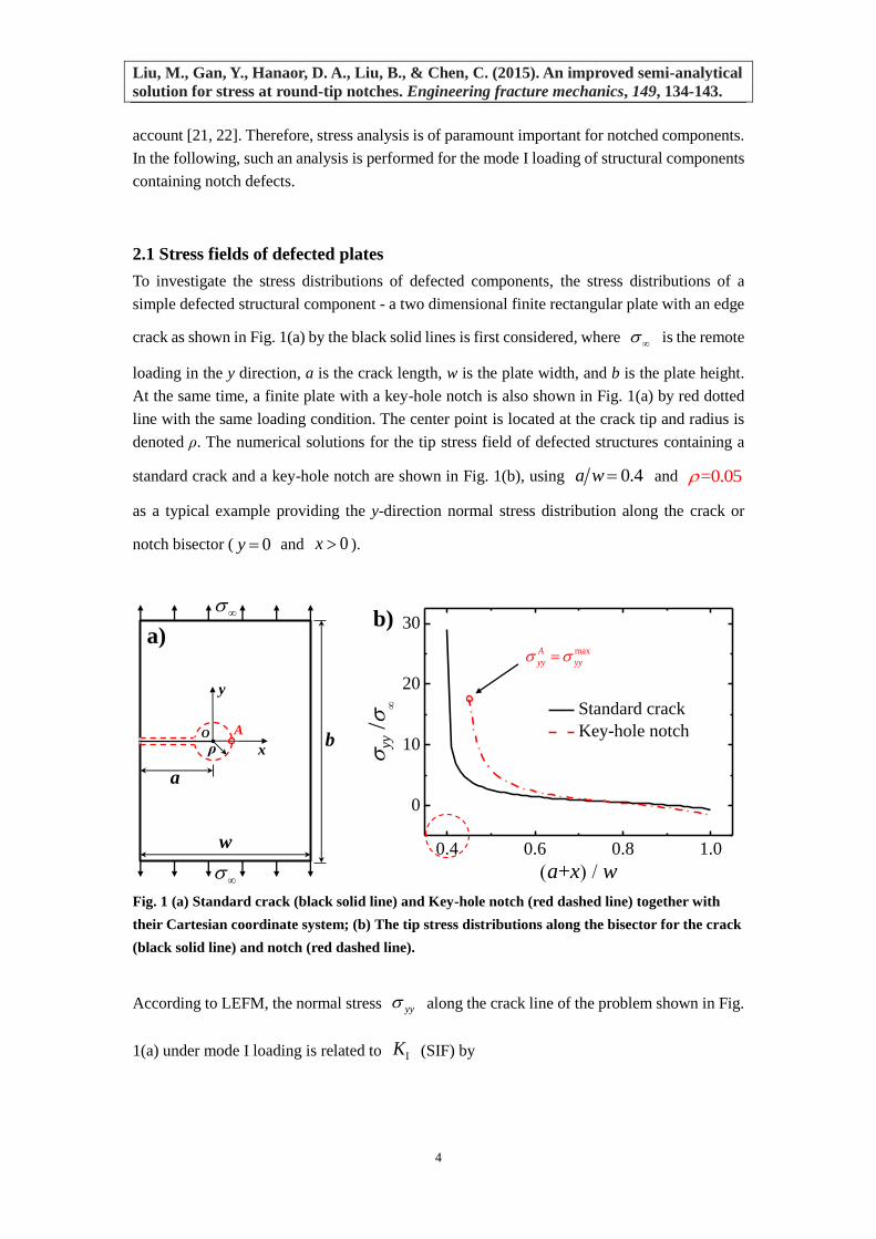
2.1 Stress fields of defected plates
To investigate the stress distributions of defected components, the stress distributions of a
simple defected structural component - a two dimensional finite rectangular plate with an edge
crack as shown in Fig. 1(a) by the black solid lines is first considered, where is the remote
loading in the y direction, a is the crack length, w is the plate width, and b is the plate height.
At the same time, a finite plate with a key-hole notch is also shown in Fig. 1(a) by red dotted
line with the same loading condition. The center point is located at the crack tip and radius is
denoted ρ. The numerical solutions for the tip stress field of defected structures containing a
standard crack and a key-hole notch are shown in Fig. 1(b), using 0.4a w and =0.05
as a typical example providing the y-direction normal stress distribution along the crack or
notch bisector ( 0y and 0x ).
Fig. 1 (a) Standard crack (black solid line) and Key-hole notch (red dashed line) together with
their Cartesian coordinate system; (b) The tip stress distributions along the bisector for the crack
(black solid line) and notch (red dashed line).
According to LEFM, the normal stress yy along the crack line of the problem shown in Fig.
1(a) under mode I loading is related to K (SIF) by
O
ρb
w
a
x
y
A
a)
0.4 0.6 0.8 1.0
0
10
20
30
yy
/
a+x w
Standard crack
Key-hole notch
maxA
yy yy
b)
Liu, M., Gan, Y., Hanaor, D. A., Liu, B., & Chen, C. (2015). An improved semi-analytical
solution for stress at round-tip notches. Engineering fracture mechanics, 149, 134-143.
5
, 02
yy
Kx
x
, (1)
where K is given by
= =K a f a w , , (2)
Here, f is the geometric shape factor for unconstrained specimens and is given by [34]
2 3 41.12 0.23 10.56 21.74 30.42f . (3)
According to Ref. [34], the error of Eq. (3) is less than 0.5% for 1b w and 0.6a w .
Eq. (1) is the asymptotic solution of the crack tip stress field, which is accurate only near the
crack tip. It is noted that, for a crack in an infinitely large plate, an exact solution is available
for the stress field, which is valid not only at the crack tip but also for the far field. The
corresponding normal stress along the crack line has the form of [35, 36],
2= , 0
2yy
K x ax
a x ax
, (4)
where K is the stress intensity factor. In this study, we extended Eq. (4) to finite width plates
with edge cracks by assuming K has the same form as Eq. (2).
For key-hole notches (i.e., cracks having a hole at their tip as represented in Fig. 1(a) by the red
dashed line), the stress singularity can be removed due to the existence of the hole. Kullmer
and Richard [19] obtained closed-form solution for the asymptotical elastic stress distribution
around a central slit ending in a circular hole in an infinite large disk. According to their solution,
the y-direction normal stress component along the notch bisector can be expressed as
2 35 5
4 3 ,2 24 2
yy
Kx
x x xx
. (5)
Considering the introduced effective crack length, a a , the corresponding effective SIF
for components with finite geometry can be assumed to have the following form
=K a f . (6)
It can be seen from Eq. (5) that the normal stress component yy decreases with increasing
distance from the edge of the notch, reaching its maximum value at the notch tip, that is,
max 33
22yy yy x
K af
. (7)
Note that Eq. (5) is based upon the assumption that the radius of the crack-tip-hole is small
Liu, M., Gan, Y., Hanaor, D. A., Liu, B., & Chen, C. (2015). An improved semi-analytical
solution for stress at round-tip notches. Engineering fracture mechanics, 149, 134-143.
6
compared to the crack length (e.g., 0.1a ). For plates with a large tip-hole relative to the
crack length, there is yet no established formula to reliably predict the maximum stress. In the
following section, a semi-analytical formula to predict the maximum stress around key-hole
notch tips will be developed.
2.2 Prediction of notch tip maximum stress
For the key-hole notched component shown in Fig. 1(a), three major factors affecting the notch
tip stress distribution. First, the crack induced stress can be estimated in accordance with Eq.
(4). The presence of the hole at the crack tip results in crack blunting, thus removing the stress
singularity. As crack tip stress singularity is related to crack length, the key-hole induced
blunting effect corresponds to the crack length. Secondly, as a result of the limited plate width,
w, compared to the standard crack with length a (effective bearing width of w a ), the
effective load bearing area along the crack bisector 0y is reduced to w a when
there exists a round hole with radius ρ at the crack tip. The stress equilibrium factor can be
derived from the force and torque balance by comparing stress fields in cases for cracks with
and without the hole using corresponding linear approximations of the normal stress along the
crack bisector. Thirdly, for a finite rectangular plate significant stress concentration occurs
around the circular hole. Taking above three majors effects into account, a semi-analytical
model to predict the notch tip maximum stress can be assumed to be
max
2=
2yy s t
af K K
a
, (8)
where sK denotes the stress equilibrium factor based on the force and torque balance effect,
and it can be obtained as
2
s
w aK
w a
. (9)
The stress concentration factor tK of a circular hole in a finite plate subject to uniaxial tension
can be approximated by [37]
1 22 2
2 1 1tKw w
, (10)
which increases from 3 monotonically with ρ/w. It can be seen from Eq. (8) that the maximum
stress at the notch tip, max
yy , is related to geometrical parameters (plate width w, crack length
a, and key-hole radius ρ) and loading conditions ( remote tensile stress ). However, it is
worth noting that the aspect ratio b w of the finite rectangular plate has a significant impact
Liu, M., Gan, Y., Hanaor, D. A., Liu, B., & Chen, C. (2015). An improved semi-analytical
solution for stress at round-tip notches. Engineering fracture mechanics, 149, 134-143.
7
on the stress concentration factor only when it is less than 2.
For a semi-edge notch in a semi-infinite rectangular plate, which is common in engineering
problems, with plate width w , 1.12f should be substituted into Eq. (7) and
we obtain
max 3 36
2yy
a
. . (11)
Whereas substituting 1.12f , 1sK and 1tK into Eq. (8) for the case of
semi-infinite plate yields
max
2=3.36
2yy
a
a
. (12)
It can be seen that for the special case of semi-infinite plates, our model (Eq. (12)) and the
Kullmer-Richard model (Eq. (11)) predict similar results of the maximum stress, for small
values of a . For large values of a , however, the Kullmer-Richard model differs
significantly from our model, as illustrated in Fig. 3 and detailed in Section 3.2.
3 Finite element simulations
In order to validate the proposed semi-analytical solution (8), notch tip stress fields were
calculated numerically using the commercial finite element software package ANSYS12.0. The
plate of the model is meshed with 8-node biquadratic plane strain elements (Solid Quad 8Node
82 elements). Due to symmetry, only half of the model ( 0y ) in Fig. 1(a) is meshed and
symmetrical boundary conditions are enforced along the notch bisector ( 0y and 0x ).
The adopted loading conditions are remote tensile stress at the edge 2y b shown in
Fig. 1(a), with the stress free boundary conditions employed for the rest boundary edges. A
linear elastic material with Young’s modulus of 70GPaE and Poisson ratio 0.3 was
used with mesh sensitivity analyses conducted to ensure the numerical convergence of the
model. Considering the concentrated stress around the notch tip, graded meshes are employed
for the tip region.
3.1 Effects of aspect ratio b/w
In order to clarify the geometrical influence on the numerical simulations, several groups of
key-hole notched plates with the same notch size (crack length a and tip curvature ρ) and
different aspect ratios (b w ) were studied by FEM. All the cases are under remote uniform
Liu, M., Gan, Y., Hanaor, D. A., Liu, B., & Chen, C. (2015). An improved semi-analytical
solution for stress at round-tip notches. Engineering fracture mechanics, 149, 134-143.
8
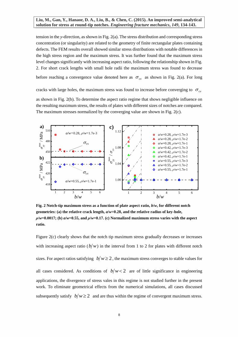
tension in the y-direction, as shown in Fig. 2(a). The stress distribution and corresponding stress
concentration (or singularity) are related to the geometry of finite rectangular plates containing
defects. The FEM results overall showed similar stress distributions with notable differences in
the high stress region and the maximum stress. It was further found that the maximum stress
level changes significantly with increasing aspect ratio, following the relationship shown in Fig.
2. For short crack lengths with small hole radii the maximum stress was found to decrease
before reaching a convergence value denoted here as cv as shown in Fig. 2(a). For long
cracks with large holes, the maximum stress was found to increase before converging to cv
as shown in Fig. 2(b). To determine the aspect ratio regime that shows negligible influence on
the resulting maximum stress, the results of plates with different sizes of notches are compared.
The maximum stresses normalized by the converging value are shown in Fig. 2(c).
Fig. 2 Notch-tip maximum stress as a function of plate aspect ratio, b/w, for different notch
geometries: (a) the relative crack length, a/w=0.28, and the relative radius of key-hole,
ρ/w=0.0017; (b) a/w=0.55, and ρ/w=0.17. (c) Normalized maximum stress varies with the aspect
ratio.
Figure 2(c) clearly shows that the notch tip maximum stress gradually decreases or increases
with increasing aspect ratio ( b w ) in the interval from 1 to 2 for plates with different notch
sizes. For aspect ratios satisfying 2b w , the maximum stress converges to stable values for
all cases considered. As conditions of 2b w are of little significance in engineering
applications, the divergence of stress vales in this regime is not studied further in the present
work. To eliminate geometrical effects from the numerical simulations, all cases discussed
subsequently satisfy 2b w and are thus within the regime of convergent maximum stress.
450
480
510
1 2 3 4 5 6
418
420
422
1 2 3 4 5 6
1.00
1.04
1.08
1.12
cv
cv
m
ax
yy /
MP
a a/w=0.28, /w=1.7e-3
a/w=0.55, /w=1.7e-1
m
ax
yy /
MP
a
b/w
m
ax
yy /
cv
b/w
a/w=0.28, /w=1.7e-3
a/w=0.28, /w=1.7e-2
a/w=0.28, /w=1.7e-1
a/w=0.42, /w=1.7e-3
a/w=0.42, /w=1.7e-2
a/w=0.42, /w=1.7e-1
a/w=0.55, /w=1.7e-3
a/w=0.55, /w=1.7e-2
a/w=0.55, /w=1.7e-1
a)
b)
c)
Liu, M., Gan, Y., Hanaor, D. A., Liu, B., & Chen, C. (2015). An improved semi-analytical
solution for stress at round-tip notches. Engineering fracture mechanics, 149, 134-143.
9
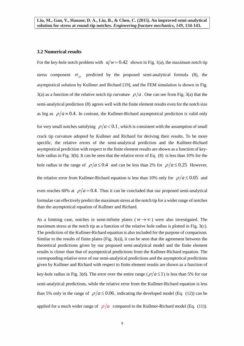
3.2 Numerical results
For the key-hole notch problem with 0.42a w shown in Fig. 1(a), the maximum notch tip
stress component yy predicted by the proposed semi-analytical formula (8), the
asymptotical solution by Kullmer and Richard [19], and the FEM simulation is shown in Fig.
3(a) as a function of the relative notch tip curvature a . One can see from Fig. 3(a) that the
semi-analytical prediction (8) agrees well with the finite element results even for the notch size
as big as 0.4a . In contrast, the Kullmer-Richard asymptotical prediction is valid only
for very small notches satisfying 0.1a , which is consistent with the assumption of small
crack tip curvature adopted by Kullmer and Richard for deriving their results. To be more
specific, the relative errors of the semi-analytical prediction and the Kullmer-Richard
asymptotical prediction with respect to the finite element results are shown as a function of key-
hole radius in Fig. 3(b). It can be seen that the relative error of Eq. (8) is less than 10% for the
hole radius in the range of 0.4a and can be less than 2% for 0.25a However,
the relative error from Kullmer-Richard equation is less than 10% only for 0.05a and
even reaches 60% at 0.4a . Thus it can be concluded that our proposed semi-analytical
formulae can effectively predict the maximum stress at the notch tip for a wider range of notches
than the asymptotical equation of Kullmer and Richard.
As a limiting case, notches in semi-infinite plates ( w ) were also investigated. The
maximum stress at the notch tip as a function of the relative hole radius is plotted in Fig. 3(c).
The prediction of the Kullmer-Richard equation is also included for the purpose of comparison.
Similar to the results of finite plates (Fig. 3(a)), it can be seen that the agreement between the
theoretical predictions given by our proposed semi-analytical model and the finite element
results is closer than that of asymptotical predictions from the Kullmer-Richard equation. The
corresponding relative error of our semi-analytical predictions and the asymptotical predictions
given by Kullmer and Richard with respect to finite element results are shown as a function of
key-hole radius in Fig. 3(d). The error over the entire range ( 1a ) is less than 5% for our
semi-analytical predictions, while the relative error from the Kullmer-Richard equation is less
than 5% only in the range of 0.06a , indicating the developed model (Eq. (12)) can be
applied for a much wider range of a compared to the Kullmer-Richard model (Eq. (11)).
Liu, M., Gan, Y., Hanaor, D. A., Liu, B., & Chen, C. (2015). An improved semi-analytical
solution for stress at round-tip notches. Engineering fracture mechanics, 149, 134-143.
10
Fig. 3 (a) Normalized maximum stress as a function of the relative key-hole radius. (b) The
relative error with respect to FEM results as a function of relative key-hole radius. (c) and (d)
respectively show the normalized maximum stress and the relative error for the case of a semi-
infinite plate.
Recall that the semi-analytical equation is based on the assumption that three mechanisms of
crack tip bluntness, stress concentration and stress equilibrium exhibit an interplay at the notch
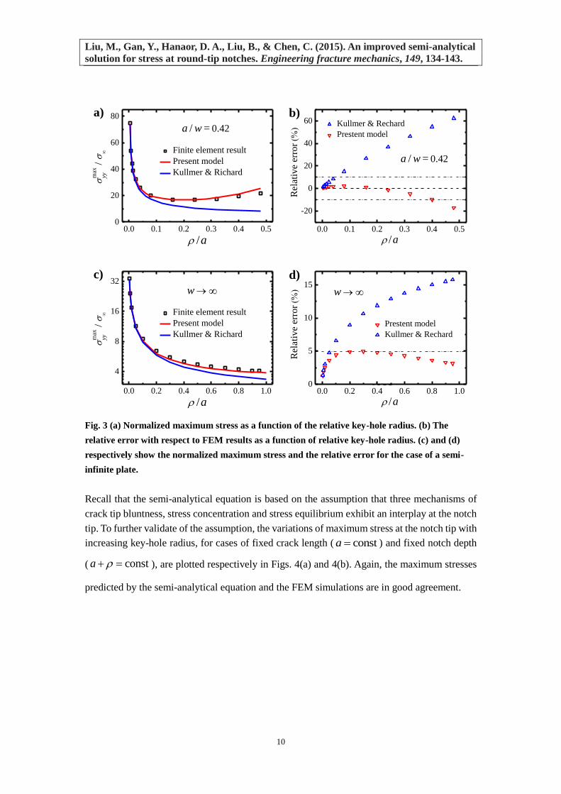
tip. To further validate of the assumption, the variations of maximum stress at the notch tip with
increasing key-hole radius, for cases of fixed crack length ( consta ) and fixed notch depth
( consta ), are plotted respectively in Figs. 4(a) and 4(b). Again, the maximum stresses
predicted by the semi-analytical equation and the FEM simulations are in good agreement.
a)
0.0 0.1 0.2 0.3 0.4 0.50
20
40
60
80
max
yy /
/ a
Finite element result
Present model
Kullmer & Richard
a / w = 0.42
b)
0.0 0.1 0.2 0.3 0.4 0.5
-20
0
20
40
60
a / w = 0.42
Rel
ativ
e er
ror
/ a
Kullmer & Rechard
Prestent model
0.0 0.2 0.4 0.6 0.8 1.0
4
8
16
32
m
ax
yy /
/ a
Finite element result
Present model
Kullmer & Richard
w
c)
0.0 0.2 0.4 0.6 0.8 1.00
5
10
15
Rel
ativ
e er
ror
/ a
Prestent model
Kullmer & Rechard
w
d)
Liu, M., Gan, Y., Hanaor, D. A., Liu, B., & Chen, C. (2015). An improved semi-analytical
solution for stress at round-tip notches. Engineering fracture mechanics, 149, 134-143.
11
Fig. 4 The relationship between the dimensionless maximum stress and the relative key-hole
radius: (a) Fixed crack length (a=const); (b) Fixed notch depth (a+ρ=const).
For fixed crack length values ( consta ), Fig. 4(a) clearly shows the competition of the three
aforementioned mechanisms. As a result, the maximum stress decreases first and then increases
with increasing key-hole size. This non-monotonic trend is more obvious for longer cracks. For
a fixed key-hole radius, the resulting maximum stress increases with crack length. Longer
cracks result in a smaller effective bearing area, and so the maximum notch tip stresses are
larger. However, for cases with fixed notch depth ( consta ), there is a monotonically
decreasing trend of the maximum stress, as shown in Fig. 4(b). This arises as a constant
effective bearing area is maintained, and the remaining factors influencing the maximum stress
are thus crack tip bluntness and stress concentration. The combined effect of these two factors
yields a decreasing trend of stress with key-hole radius. As is evident from Fig. 4, three principal
factors affect the maximum stress of key-hole notched components, crack tip hole bluntness,
stress concentration around the key-hole due to the finite plate size, and the reduction of the
effective bearing area. Combining these three factors, we obtained the semi-analytical equation
for predicting the maximum stress and validated the predictions with the FEM results.
4. Stress analysis of Key-hole-like (U- and blunt V-) notches
In order to further expand the application of the developed formula, we will generalize the semi-
analytical model (Eq. (8)) to key-hole-like notches (i.e., U- and blunt V-notches) and further
examine failure criteria for notched components. In the past decade most studies on the brittle
fracture of components containing key-hole-like notches were based upon the NFM extension
of classical fracture mechanics, pertaining to notched engineering structures [13-16]. Various
failure criteria in the field of NFM were developed using the concepts of NSIF and NFT, among
others. These criteria usually involve a number of model parameters, requiring complex fitting
of experimental data, motivating the use of reliable analytical models. Here we apply the semi-
analytical equation proposed in the Section 2 to investigate the maximum stress of U-notches
and blunt V-notches shown in Fig. 5(a).
0.00 0.05 0.10 0.15 0.200
50
100
150
m
ax
yy /
/ w
a/w=0.28 (FEM)
a/w=0.28 (Theoretical)
a/w=0.42 (FEM)
a/w=0.42 (Theoretical)
a/w=0.55 (FEM)
a/w=0.55 (Theoretical)
a)
0.00 0.05 0.10 0.15 0.200
75
150
225
m
ax
yy /
/ w
(a+/w=0.42 (FEM)
(a+/w=0.42 (Theoretical)
(a+/w=0.55 (FEM)
(a+/w=0.55 (Theoretical)
(a+/w=0.68 (FEM)
(a+/w=0.68 (Theoretical)
b)
Liu, M., Gan, Y., Hanaor, D. A., Liu, B., & Chen, C. (2015). An improved semi-analytical
solution for stress at round-tip notches. Engineering fracture mechanics, 149, 134-143.
12
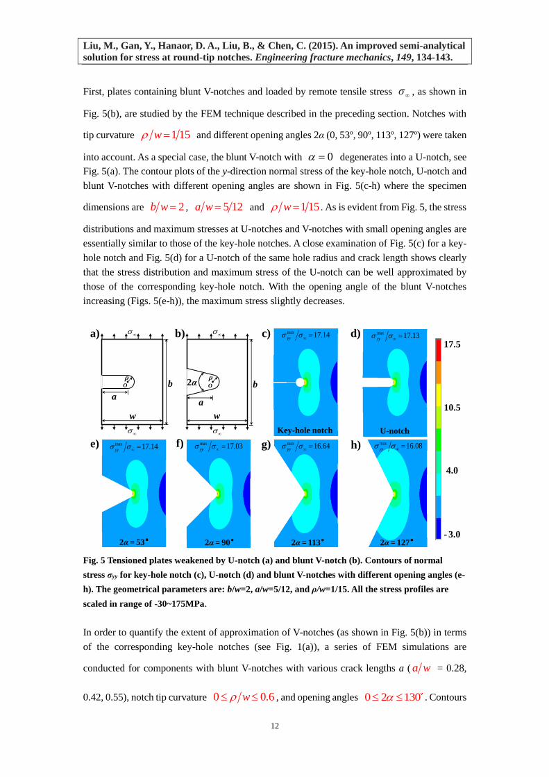
First, plates containing blunt V-notches and loaded by remote tensile stress , as shown in
Fig. 5(b), are studied by the FEM technique described in the preceding section. Notches with
tip curvature 1 15w and different opening angles 2α (0, 53º, 90º, 113º, 127º) were taken
into account. As a special case, the blunt V-notch with 0 degenerates into a U-notch, see
Fig. 5(a). The contour plots of the y-direction normal stress of the key-hole notch, U-notch and
blunt V-notches with different opening angles are shown in Fig. 5(c-h) where the specimen
dimensions are 2b w , 5 12a w and 1 15w . As is evident from Fig. 5, the stress
distributions and maximum stresses at U-notches and V-notches with small opening angles are
essentially similar to those of the key-hole notches. A close examination of Fig. 5(c) for a key-
hole notch and Fig. 5(d) for a U-notch of the same hole radius and crack length shows clearly
that the stress distribution and maximum stress of the U-notch can be well approximated by
those of the corresponding key-hole notch. With the opening angle of the blunt V-notches
increasing (Figs. 5(e-h)), the maximum stress slightly decreases.
Fig. 5 Tensioned plates weakened by U-notch (a) and blunt V-notch (b). Contours of normal
stress σyy for key-hole notch (c), U-notch (d) and blunt V-notches with different opening angles (e-
h). The geometrical parameters are: b/w=2, a/w=5/12, and ρ/w=1/15. All the stress profiles are
scaled in range of -30~175MPa.
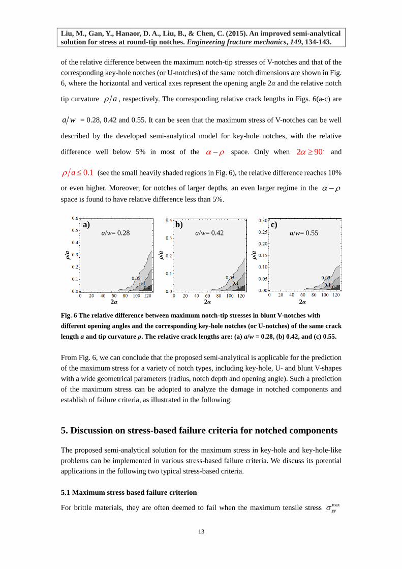
In order to quantify the extent of approximation of V-notches (as shown in Fig. 5(b)) in terms
of the corresponding key-hole notches (see Fig. 1(a)), a series of FEM simulations are
conducted for components with blunt V-notches with various crack lengths a ( a w = 0.28,
0.42, 0.55), notch tip curvature 0 0.6w , and opening angles 0 2 130 . Contours
max 17.03yy
2α= 90°
f)
Key-hole notch
c) max 17.14yy
U-notch
d) max 17.13yy
2α= 53°
e) max 17.14yy
2α= 113°
g) max 16.64yy
2α= 127°
h) max 16.08yy
b)
bO
ρ
w
a
2α
a)
bO
ρ
w
a
17.5
- 3.0
10.5
4.0
Liu, M., Gan, Y., Hanaor, D. A., Liu, B., & Chen, C. (2015). An improved semi-analytical
solution for stress at round-tip notches. Engineering fracture mechanics, 149, 134-143.
13
of the relative difference between the maximum notch-tip stresses of V-notches and that of the
corresponding key-hole notches (or U-notches) of the same notch dimensions are shown in Fig.
6, where the horizontal and vertical axes represent the opening angle 2α and the relative notch
tip curvature a , respectively. The corresponding relative crack lengths in Figs. 6(a-c) are
a w = 0.28, 0.42 and 0.55. It can be seen that the maximum stress of V-notches can be well
described by the developed semi-analytical model for key-hole notches, with the relative
difference well below 5% in most of the space. Only when 2 90 and
0.1a (see the small heavily shaded regions in Fig. 6), the relative difference reaches 10%
or even higher. Moreover, for notches of larger depths, an even larger regime in the
space is found to have relative difference less than 5%.
Fig. 6 The relative difference between maximum notch-tip stresses in blunt V-notches with
different opening angles and the corresponding key-hole notches (or U-notches) of the same crack
length a and tip curvature ρ. The relative crack lengths are: (a) a/w = 0.28, (b) 0.42, and (c) 0.55.
From Fig. 6, we can conclude that the proposed semi-analytical is applicable for the prediction
of the maximum stress for a variety of notch types, including key-hole, U- and blunt V-shapes
with a wide geometrical parameters (radius, notch depth and opening angle). Such a prediction
of the maximum stress can be adopted to analyze the damage in notched components and
establish of failure criteria, as illustrated in the following.
5. Discussion on stress-based failure criteria for notched components
The proposed semi-analytical solution for the maximum stress in key-hole and key-hole-like
problems can be implemented in various stress-based failure criteria. We discuss its potential
applications in the following two typical stress-based criteria.
5.1 Maximum stress based failure criterion
For brittle materials, they are often deemed to fail when the maximum tensile stress max
yy
a) b) c)
2α
ρ/a
ρ/a
2α 2α
ρ/a
a/w= 0.28 a/w= 0.42 a/w= 0.55
Liu, M., Gan, Y., Hanaor, D. A., Liu, B., & Chen, C. (2015). An improved semi-analytical
solution for stress at round-tip notches. Engineering fracture mechanics, 149, 134-143.
14
(usually the normal stress at the notch tip of the cross section, as labeled in Fig. 1(b)) reaches
the material’s failure strength fs [38]. Therefore, a simple method of predicting failure
strength is based on the criterion of
max
yy fs . (13)
This failure criterion can be applied for assessing cracks with small key-holes and notches with
large holes, including U-notches and blunt V-notches [39]. Using the semi-analytical model
(i.e., Eq. (8)) in conjunction with Eq. (13), one can predict the maximum admissible load of
plates with notches.
5.2 Notch tip stress field based fracture criteria
In general, most failure criteria for notched components are based on the notch tip stress field.
In these criteria, the notch tip maximum stress has been introduced into the stress field as a key
parameter [21-24]. For example, in the widely used stress field solution for rounded-tip V-
notches obtained by Filippi et al. [21], the y-direction normal stress along the bisector for a
notch with opening angle 2α and notch tip curvature ρ is given by
1 1max ,yy yy r f
. (14)
where r is the polar coordinate, 1 is a function of the notch opening angle. This equation has
been found to be in good agreement with finite element results in the high stress region around
the notch tip [21]. Subsequently, this stress field has further been extended to plates with finite
width [22].
In addition, the NSIF, which indicates the stress intensity at the notch tip, can be related to the
maximum stress by the following equation
max 2 ,V
yyK g (15)
It can be seen from Eqs. (14) and (15) that the maximum stress max
yy is contained in the
notch tip stress field based failure criteria as an unknown parameter and varies with the
geometry size of the components and the load conditions. By substituting the semi-analytical
equation (Eq. (8)) into Eqs. (14) and (15), the y-direction normal stress yy and NSIF VK
can be directly related to the external load .
6. Conclusions
In this paper, the stress distributions of notched components under mode I loading are
investigated. Based upon the combined effects of three mechanisms, crack tip bluntness, stress
concentration and stress equilibrium; a semi-analytical formula is proposed to predict the notch
Liu, M., Gan, Y., Hanaor, D. A., Liu, B., & Chen, C. (2015). An improved semi-analytical
solution for stress at round-tip notches. Engineering fracture mechanics, 149, 134-143.
15
tip maximum stress. Due to the competition of the three aforementioned mechanisms, the
maximum stress at the notch tip first decreases and then increases with increasing notch tip
radius for a fixed crack length. For constant notch depth the maximum stress is found to
decrease monotonically with increasing notch tip radius. An extensive comparison between the
theoretical prediction of the maximum stresses and FEM results was shown to validate the new
semi-analytical model.
It is further found that the stress fields of U-notches and blunt V-notches with small tip radii
and opening angles are similar to those of key-hole notches. The proposed semi-analytical
model can therefore be applied to predict the maximum stress at the tip of these notches and
establish appropriate stress-based failure criteria. The model can also be applied to edge
notched infinite plates. The presently developed approach can be extended to round-tip center
notches and can further be generalized to incorporate alternative loading conditions including
localized loads.
Acknowledgements
The authors are grateful for the financial support of this work by the National Natural Science
Foundation of China (No. 11472149), the National Basic Research Program of China (No.
2011CB610305), and the Tsinghua University Initiative Scientific Research Program (No.
2014z22074).
References
[1] Kuang ZB. The stress field near the blunt crack tip and the fracture criterion. Eng. Fract.
Mech. 1982; 16(1): 19-33.
[2] Glinka G, Newport A. Universal features of elastic notch-tip stress fields. Int. J. Fat. 1987;
9(3): 143-150.
[3] Lazzarin P, Tovo R. A unified approach to the evaluation of linear elastic stress fields in
the neighborhood of cracks and notches. Int. J. Fract. 1996; 78(1): 3-19.
[4] Gomez FJ, Guinea GV, Elices M. Failure criteria for linear elastic materials with U-notches.
Int. J. Fract. 2006; 141(1-2): 99-113.
[5] Torabi AR, Pirhadi E. Stress-based criteria for brittle fracture in key-hole notches under
mixed mode loading. Eur. J. Mech. Solids/A 2015; 49: 1-12.
[6] Gómez FJ, Elices M, Berto F, Lazzarin P. Fracture of U-notched specimens under mixed
mode: experimental results and numerical predictions. Eng. Fract. Mech. 2009; 76(2): 236-
249.
[7] Ayatollahi MR, Torabi AR. Brittle fracture in rounded-tip V-shaped notches. Mater. Design
2010; 31(1): 60-67.
[8] Berto F, Zappalorto M. Fictitious notch rounding concept applied to V-notches with end
holes under mode I loading. Int. J. Fract. 2011; 171(1): 91-98.
[9] Torabi AR, Abedinasab SM. Brittle fracture in key-hole notches under mixed mode
Liu, M., Gan, Y., Hanaor, D. A., Liu, B., & Chen, C. (2015). An improved semi-analytical
solution for stress at round-tip notches. Engineering fracture mechanics, 149, 134-143.
16
loading: Experimental study and theoretical predictions. Eng. Fract. Mech. 2015; 134: 35-
53.
[10] Torabi AR, Abedinasab SM. Fracture study on key-hole notches under tension: two brittle
fracture criteria and notch fracture toughness measurement by the disk test. Exper. Mech.
2015; 55(2): 393-401.
[11] Torabi AR, Fakoor M, Pirhadi E. Tensile fracture in coarse-grained polycrystalline
graphite weakened by a U-shaped notch. Eng. Fract. Mech. 2013; 111: 77-85.
[12] Anderson TL. Fracture mechanics: fundamentals and applications. Boca Raton: CRC press;
2005.
[13] Radaj D. State - of - the - art review on extended stress intensity factor concepts. Fat. Fract.
Eng. Mater. Struct. 2014; 37(1): 1-28.
[14] Gomez FJ, Elices M, Valiente A. Cracking in PMMA containing U-shaped notches. Fat.
Fract. Eng. Mater. Struct. 2000; 23: 795-803.
[15] Carpinteri A, Cornetti P, Sapora A. Brittle failures at rounded V-notches: a finite fracture
mechanics approach. Int. J. Fract. 2011; 172(1): 1-8.
[16] Gomez FJ, Guinea GV, Elices M. Failure criteria for linear elastic materials with U-notches.
Int. J. Fract. 2006; 141(1-2): 99-113.
[17] Erdogan F, Sih GC, On the crack extension in plates under plane loading and transverse
shear. J. Basic Eng. 1963; 85(4): 519-525.
[18] Creager M, Paris PC, Elastic field equations for blunt cracks with reference to stress
corrosion cracking. Int. J. Fract. Mech. 1967; 3(4): 247-252.
[19] Kullmer G, Richard HA. Influence of the root radius of crack-like notches on the fracture
load of brittle components. Arch. Appl. Mech. 2006; 76(11-12): 711-723.
[20] Lazzarin P, Berto F, Ayatollahi MR. Brittle failure of inclined key-hole notches in isostatic
graphite under in‐plane mixed mode loading. Fat. Fract. Eng. Mater. Struct. 2013; 36(9):
942-955.
[21] Filippi S, Lazzarin P, Tovo R. Developments of some explicit formulas useful to describe
elastic stress fields ahead of notches in plates. Int. J. Solids Struct. 2002; 39(17): 4543-
4565.
[22] Filippi S, Lazzarin P. Distributions of the elastic principal stress due to notches in finite
size plates and rounded bars uniaxially loaded. Int. J. Fat. 2004; 26(4): 377-391.
[23] Zappalorto M, Lazzarin P. In-plane and out-of-plane stress field solutions for V-notches
with end holes. Int. J. Fract. 2011; 168(2): 167-180.
[24] Zappalorto M, Carraro PA. Stress distributions for blunt cracks and radiused slits in
anisotropic plates under in-plane loadings. Int. J. Solids Struct. 2015; 56-57: 36-141.
[25] Bazant ZP. Size effect in blunt fracture: concrete, rock, metal. J. Eng. Mech. 1984; 110:
518-535.
[26] Smith E. Underpinning of a simple blunt flaw fracture initiation relation. Int. J. Fract. 2005;
131: 401-405.
[27] Leguillon D, Piat R. Fracture of porous materials–Influence of the pore size. Eng. Fract.
Mech. 2008; 75: 1840-1853.
[28] Liu M, Chen C. A micromechanical analysis of the fracture properties of saturated porous
media. Int. J. Solids Struct. 2015; 63:32-38.
Liu, M., Gan, Y., Hanaor, D. A., Liu, B., & Chen, C. (2015). An improved semi-analytical
solution for stress at round-tip notches. Engineering fracture mechanics, 149, 134-143.
17
[29] Irwin GR. Analysis of stresses and strains near the end of a crack traversing a plate. ASME
J. Appl. Mech. 1957; 24: 361-364.
[30] Fett T, Munz D. Stress intensity factors and weight functions. Vol. 1. Comput. Mech. 1997.
[31] Bazant ZP. Size effect in blunt fracture: concrete, rock, metal. J. Eng. Mech. 1984; 110(4):
518-535.
[32] Leguillon D, Piat R. Fracture of porous materials-Influence of the pore size. Eng. Fract.
Mech. 2008; 75(7): 1840-1853.
[33] Torabi A R. Fracture assessment of U-notched graphite plates under tension. Int. J. Fract.
2013; 181(2): 285-292.
[34] Tada H, Paris PC, Irwin GR. The stress analysis of cracks handbook. New York: ASME
press; 2000.
[35] Sih GC, Liebowitz H. Mathematical theories of brittle fracture. In Fracture (Vol. 2, pp. 67-
190) New York: Academic Press; 1968.
[36] Jia YJ, Shi MX, Zhao Y, Liu B. A better estimation of plastic zone size at the crack tip
beyond Irwin's model. ASME J. Appl. Mech. 2013; 80(5): 051014.
[37] Heywood RB. Designing by Photoelastacity. London: Chapman and Hall press; 1952.
[38] Hertel D, Fett T, Munz D. Strength predictions for notched alumina specimens. J. Euro.
Cera. Soc. 1998; 18(4): 329-338.
[39] Gómez FJ, Elices M. A fracture criterion for blunted V-notched samples. Int. J. Fract. 2004;
127(3): 239-264.