an-hpdsc-assembly instructions on hybridpack dsc
TRANSCRIPT
Application Note Please read the Important Notice and Warnings at the end of this document V 1.3
www.infineon.com page 1 of 18 2020-08-25
AN-HPDSC-Assembly instructions on HybridPACK DSC
Application Note
HybridPACK DSC
About this document
This application note contains information on HybridPACKTM DSC regarding assembly and mounting instructions
Scope and purpose
The HybridPACK™ DSC module has an optimized geometry for enhanced thermal conductivity. In order to
utilize this module properly, it is relevant to understand the properties of the module. The application note
gives explanations on mounting and assembly of the module. Furthermore, it gives guidance on how to design the printed circuit boards with the correct module tolerance.
Intended audience
Engineers and operators involved in developing a system using the HybridPACK™ DSC power module.
Table of contents
About this document ....................................................................................................................... 1
Table of contents ............................................................................................................................ 1
1 Introduction to HybridPACKTM DSC Power Module ...................................................................... 2
2 Assembly instructions ............................................................................................................ 3
2.1 General requirements on the heatsink ................................................................................................... 3 2.2 Application of thermal interface material .............................................................................................. 4
2.3 Mounting force coordination (compressive force) ................................................................................ 5 2.4 Interconnection: power terminal and signal pin ................................................................................... 6
2.4.1 Mounting options for the power terminal ......................................................................................... 6 2.5 Assembly of the reference heatsink ........................................................................................................ 8 2.5.1 Mounting screws for the reference clamping .................................................................................. 11 2.5.2 Stacking multiple modules .............................................................................................................. 11
2.6 Example of the PCB mounting .............................................................................................................. 12
2.6.1 PCB hole size definition considering the tolerance chain .............................................................. 14
3 Traceability, Data Matrix and Part Markings ............................................................................. 15
4 Storage and Transport ........................................................................................................... 16
Revision history............................................................................................................................. 17

Application Note 2 of 18 V 1.3
2020-08-25
Application Note HybridPACK DSC
Introduction to HybridPACKTM DSC Power Module
1 Introduction to HybridPACKTM DSC Power Module
The trademark of HybridPACK™ DSC covers molded IGBT power module devices which have bi-directional
paths for heat-dissipation by so called double side cooling technology.
The HybridPACK™ DSC-S and HybridPACK™ DSC-L are two different types of the HybridPACK™ DSC categorized by the size, number of the switches and their internal structure.
a) HybridPACKTM DSC-S b) HybridPACKTM DSC-L
HybridPACKTM DSC-S1 & S2
- FF400R07A01E3_S6 (DSC-S1)
- FF450R08A03P2 (DSC-S2)
HybridPACKTM DSC-L
- FS200R07A02E3_S6
Dimension [Length x width x height]
- pin / terminal excluded 42.0 x 42.4 x4.7 [mm] 86.0 x 43.0 x 6.0 [mm]
Module configuration Half-bridge Six Pack (B6)
Power rating 700V / 400A (DSC-S1)
750V / 450A (DSC-S2) 700V / 200A
Additional feature On-chip temperature sensor
On-chip current sensor
2 x NTC
On-chip Current sensor
Figure 1: a) HybridPACKTM DSC-S and b) HybridPACKTM DSC-L.

Application Note 3 of 18 V 1.3
2020-08-25
Application Note HybridPACK DSC
Assembly instructions
2 Assembly instructions
An adequate integration of the heatsink is a basic condition to use the HybridPACKTM DSC module properly.
The fundamentally different construction in both DSC-S&L packages requires a different approach for
designing and assembling a heatsink. Therefore, a consideration on following points is strongly recommended as a starting point:
Mechanical feature of the heat sink
Application of thermal interface material
Choosing a proper clamping concept
Creepage and clearance coordination
2.1 General requirements on the heatsink
The power loss occurring in the module has to be dissipated in order to avoid exceeding the maximum
permissible chip function temperature specified in the datasheet during switching operation (Tvj_op = 150 °C continuously and Tvj_op = 175 °C during short time). Therefore, the design of cooling the system/heatsink is of
great importance to achieve the target performance.
The purity condition of the surface in the area where the module has contact with heatsink is also essential, as
this interface has decisive influence on the heat transfer of the entire system. Therefore, it is essential to keep the contact surface of the module and heatsink free from any particle contamination.
Additionally, special care has to be taken concerning the isolation distance between the module pins and
heatsink for the HybridPACKTM DSC, due to the thin and compact construction of the module.
It is strictly recommended to limit the width of the heatsink and substrate contact area to ensure sufficient
isolation coordination (e.g. based on IEC 60664-1)
Module type Contact surface quality Restriction of heatsink width
HybridPACKTM DSC-S Surface flatness ≤50 µm
Surface roughness Rz≤10 µm 29 mm < heat sink width < 31 mm
HybridPACKTM DSC-L Surface flatness ≤50 µm
Surface roughness Rz≤10 µm 23 mm < heat sink width < 31 mm
Table 2.1: recommended contact surface quality and heatsink width
In case that a wider heatsink is required, an additional design-countermeasure (e.g. adding step structure) or
additional component (e.g. isolation pad) must be considered for the isolation.
As shown in Figure 2, the width and geometry of the heatsink determines the critical creepage and clearance distances.

Application Note 4 of 18 V 1.3
2020-08-25
Application Note HybridPACK DSC
Assembly instructions
Figure 2: HybridPACKTM DSC with the top and bottom heatsinks
2.2 Application of thermal interface material
To dissipate the losses from the module and to achieve a good heat flow into the heatsink, all localised cavities
of the modules have to be filled with a thermal compound. When using a heat conductive paste, a homogeneous application needs to be guaranteed.
An uniform layer of thermal paste over the top and bottom pads will fill all cavities and will at the same time not prevent any metallic contact between the exposed module surface for cooling and the heatsink surface. A compound should be selected which shows permanently elastic features in order to ensure a continuously
favourable heat transfer conductance. The paste should be applied in a way that no screw holes are
contaminated and that bolt torques are not affected.
Infineon recommends to use the OSR-500 thermal grease specified in Table 2-2 which is the same used on the
evaluation kit of the DSC Modules. Basically, The thermal grease with high thermal conductivity is recommended. Also, the thinner the Bond-line thickness the lower the thickness of thermal paste required to
achieve better thermal performance. However, the module and cooler flatness along with roughness have to be taken into account in order to choose the appropriate thickness of the thermal paste.
Name Thermal
conductivity Insulation
Minimum Bond-Line
Thickness(BLT)
Operating Range manufacturer
OSR-500 3 W/mK Yes 60um -40 / +200°C
G790 3 W/mK Yes 10um -40 / +200°C
Table 2.2: information on the thermal grease for the reference system
The mechanical drawing shown on Figure 3 is an example of pattern to apply the thermal paste on the cooler.
Using common rollers or fine toothed spatulas on the pattern will create an uniform layer of thermal paste of the Module. Infineon recommends to use a pattern of 150um thickness in order to guarantee a perfect contact
between the module,thermal paste and the cooler.

Application Note 5 of 18 V 1.3
2020-08-25
Application Note HybridPACK DSC
Assembly instructions
Figure 3:Recommended Pattern for the thermal grease
2.3 Mounting force coordination (compressive force)
The HybridPACKTM DSC is designed to be pressed by the heatsink in the application. The overall thermal performance of the system is influenced by the clamping force.
The higher the clamping force until a certain range, the better the overall thermal performance. According to
the characterization of the module, the required compression force range is located between 400N to 800N.
On the other hand, too high clamping force can produce internal stress and reduce the life time of the module.
To avoid any unnecessary high compression force, the following limits in Table 2-2 have been introduced.
The compression force above this point will not improve the thermal performance anymore, but will increase the stress to the module. To protect the module from an overcompression force, it is strongly recommended
to follow the recommendations of Table 2-2 .
mounting force reference
(data sheet value)
Maximum allowed Mounting force
Mounting force local
(One time)
700 N ≤ 850 N ≤ 150 MPa
Table 2-2: Typical clamping force coordination
Exceeding the maximum values specified in Table2-2 leads to a reduced power module lifetime.
Heat sink
Heat sink
30±1 mm
Application Note 6 of 18 V 1.3
2020-08-25
Application Note HybridPACK DSC
Assembly instructions
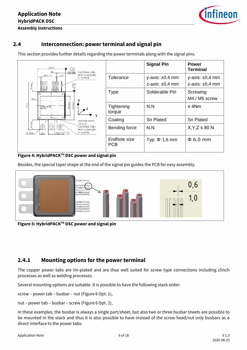
2.4 Interconnection: power terminal and signal pin
This section provides further details regarding the power terminals along with the signal pins.
Signal Pin Power Terminal
Tolerance y-axis: ±0,4 mm
z-axis: ±0,4 mm
y-axis: ±0,4 mm
z-axis: ±0,4 mm
Type Solderable Pin Screwing
M4 / M5 screw
Tightening torque
N.N ≤ 4Nm
Coating Sn Plated Sn Plated
Bending force N.N X,Y,Z ≤ 80 N
Endhole size PCB
Typ. Ф 1,6 mm Ф 6.0 mm
Figure 4: HybridPACKTM DSC power and signal pin
Besides, the special taper shape at the end of the signal pin guides the PCB for easy assembly.
Figure 5: HybridPACKTM DSC power and signal pin
2.4.1 Mounting options for the power terminal
The copper power tabs are tin-plated and are thus well suited for screw type connections including clinch processes as well as welding processes.
Several mounting options are suitable. It is possible to have the following stack order:
screw – power tab – busbar – nut (Figure 6 Opt. 1),
nut – power tab – busbar – screw (Figure 6 Opt. 2),
In these examples, the busbar is always a single part/sheet, but also two or three busbar sheets are possible to be mounted in the stack and thus it is also possible to have instead of the screw head/nut only busbars as a
direct interface to the power tabs:
x
y
z

Application Note 7 of 18 V 1.3
2020-08-25
Application Note HybridPACK DSC
Assembly instructions
e.g. screw – busbar - power tab – busbar – nut.
Further beneficial mounting options are given by the use of self-clinching nuts. Standard M4 self-clinching nuts can be used in mounting holes designed for M5 screws. Thus, a M4 self-clinching nut can be pressed into the
power tab hole and busbars can be connected with a M4 screw (preferably the same screw type as used for mounting the baseplate to the cooling system).
Opt. 1)
Opt. 2)
Opt. 3)
Opt. 4)
Screw – power tab – busbar – sc nut
Figure 6: Examples of power tab connection options
Mounting Option
Screw/Nut type Mounting torque Remarks
min. typ. max.
1,2 M5 ISO 4762 screw (M5 ISO 7090
washer)
M5 ISO4032 nut
3.6 Nm 4.0 Nm 4.4 Nm low volume production &
lab testing
1,2 M5 ISO 7380-2-A2-(TX) screw
M5 ISO6923 nut
3.6 Nm 4.0 Nm 4.4 Nm low volume production & lab testing
3 M4 ISO 7380-2-A2-(TX)
M4 self-clinching nut
e.g. “TR-S-M4-1”
PEM “S-M4-0ZI”
1.8 Nm 2.0 Nm 2.2 Nm Low to high volume production & lab testing
4 M5 ISO 7380-2-A2-(TX) screw
M5 self-clinching nut
3.6 Nm 4.0 Nm 4.4 Nm Low to high volume production & lab testing
5 welding - - - high volume production
Table 2-3: Power tab mounting options and recommended screw torque

Application Note 8 of 18 V 1.3
2020-08-25
Application Note HybridPACK DSC
Assembly instructions
The screw types in Table 2-3 give only a rough overview. Different types may be possible with same mounting torque in case the base of the head or the spot face are comparable to the given types and the busbar material is suitable for such mounting.
2.5 Assembly of the reference heatsink
The HybridPACK™ Double Side Cooling itself gives only an indication that two heatsinks are necessary. The concrete shape and interconnection of the heatsinks are dependent on the system construction.
There is no single instruction for mounting which can cover all possible case profiles. Therefore, one example
system design is introduced to give a reasonable example for the application of HybridPACKTM DSC.

Application Note 9 of 18 V 1.3
2020-08-25
Application Note HybridPACK DSC
Assembly instructions
Figure 7: Example of heatsink mounting (top: direct screwing, bottom: with clamping part)
In the example of Figure 7, clamping is realized by the additional clamping part placed on top of the heatsink(
highlighted in blue). The advantage of using an additional clamping part is that the clamping force is evenly distributed from the side to the middle of the DSC Row. Therefore, it avoids to have any gap after screwing, between the heatsink and the top/bottom of the dsc modules which could have a bad impact on the thermal performance of the DSC component placed in the middle.
While screwing the heatsink using 4xM4 screws like depicted in Figure 7, please refrain to screw with a torque
higher than 1.7 Nm to avoid any damages on the threads.
Clamping force

Application Note 10 of 18 V 1.3
2020-08-25
Application Note HybridPACK DSC
Assembly instructions
Figure 8: Example of the heatsink for double side cooling
Top Heatsink
Bottom Heatsink

Application Note 11 of 18 V 1.3
2020-08-25
Application Note HybridPACK DSC
Assembly instructions
2.5.1 Mounting screws for the reference clamping
As long as a proper compression force to the module is applied, oneis free to choose a mounting screw under the condition that the screw itself is automotive qualified and the system is reliable against mechanical shock
and vibration. The weight of the heatsink system including the three modules is an essential criterion to strengthen the stability of the system. Additionally, resonance and eigenfrequency of the heatsink system are
relevant parameters.
Figure 9: Screwing sequence for optimal torque uniformity
2.5.2 Stacking multiple modules
Thanks to its form factor, the molded component HybridPACKTM DSC has the advantage to offer a power
scalability by stacking more modules together. Hence, with an appropriate cooler design, the fact of stacking twice or thrice rows will offer higher power performance while still conserving a more compact solution than actual frame modules. Also depending on the desired applications, for example by combining a motor main inverter in addition to a generator inverter (hybrid vehicles), the HybridPACKTM DSC can be stacked differently
between DSC-S and/or DSC-L as shown in Figure 10. In this example, the possibilities are non exhaustive and
are related to the target applications. However, some combinations should be preferred to simplify the connections between the different bus bars and the power terminals.
Figure 10: Example of possible stacking combinations while using HybridPACKTM DSC products
1
2
3
4

Application Note 12 of 18 V 1.3
2020-08-25
Application Note HybridPACK DSC
Assembly instructions
Also, in order to guarantee an uniformity on temperature and mechanical stress over the different devices, the different rows should respect a clamping force symmetry along the cooler length as shown in Figure 11. While
clamping only 2 modules on the same row, the clamping force should be evenly distributed. Therefore, positioning the 2 modules on the left and right-hand sides should be preferred to distribute the clamping force
equally over the modules.
Figure 11: Recommendation on HybridPACKTM DSC position using a standard heatsink
2.6 Example of the PCB mounting
To guarantee a minimum stability of the PCB to the heatsink, and to reduce any mechanical looseness from the PCB to the heatsink and component pins, each width extremity should at least contain 2 screws and each length at least 3-4 screws. Also, to simplify the mounting of PCB to the cooler and DC link together in
production, the PCB screw holes diameters of the gate driver PCB should be identical.
In order to manage the guidance of the DSC module pins, a certain tolerance is required so that each pin of the different modules can fit uniformly to the PCB holes. The PCB drawing tolerance in the example of Figure 12 is used for the standard assembly.
Finally, the overall system design should carefully consider the tolerance chain to validate the final size of the PCB holes.
There is no specific process to mount the PCB driver board on the cooler with already placed DSC components.
However, to simplify the mounting between the PCB interface and the cooler, the easiest way is to plug all the DSC components to the PCB board before clamping them to the cooler. Some looseness should be required to avoid any mechanical stress of the pins while screwing the cooler on the driver board. Optionally, the bus bar can be screwed before clamping. In such way, the DSC components should be correctly placed over the bottom plate of the cooler and correctly plugged on the PCB.
After clamping the DSC components with the top cooler, the pins of the DSC can finally be soldered on the
driver board. For some additional details on soldering the pins of the modules, the document “General Recommendation for Assembly of infineon Packages” can be found on the web page of Infineon in the package section:
https://www.infineon.com/cms/en/product/packages/

Application Note 13 of 18 V 1.3
2020-08-25
Application Note HybridPACK DSC
Assembly instructions
Figure 12: Example of PCB hole position for screwing the standard heatsink (HybridKitTM DSC)

Application Note 14 of 18 V 1.3
2020-08-25
Application Note HybridPACK DSC
Assembly instructions
2.6.1 PCB hole size definition considering the tolerance chain
Besides the reliable solder contact between signal pin and PCB, the total tolerance chain should be considered to ensure the feasibility of the assembly.
Tolerance
Module positioning: Module - heatsink
±0.5 mm
Module tolerance:
Signal pin position
±0.4 mm
PCB assembly tolerance:
PCB – Heatsink
±0.5 mm
PCB hole position tolerance: ±0.1 mm
Table 2-4: typical example for tolerance chain-calculation
Considering all the max. dimensions to calculate the total tolerance leads to unrealistically tight tolerance
requirements. Since each tolerance is an outcome from the 6 sigma consideration which contains the term of probability, the
proper consideration on the probability needs to be considered. In general, the basic equation to add up the total sigma is known by the below equation:
Total sigma = √𝐴² + 𝐵² + 𝐶²…+ 𝑍²
Where A,B,C… Z represent the individual tolerances. In this example, 3 sigma level tolerance need to be considered to get 6 sigma level of total tolerances.
6 sigma = √3² + 3² + 3² + 3²
If the tolerance value in Table 2-4 is applied for the calculation, the total resulting deviation is about 0.4 mm.
Based on this result, the min. PCB hole size for the DSC Pins can be calculated: ≥ Ф1,6 mm
Figure 15: Pin tolerance versus PCB hole
Application Note 15 of 18 V 1.3
2020-08-25
Application Note HybridPACK DSC
Traceability, Data Matrix and Part Markings
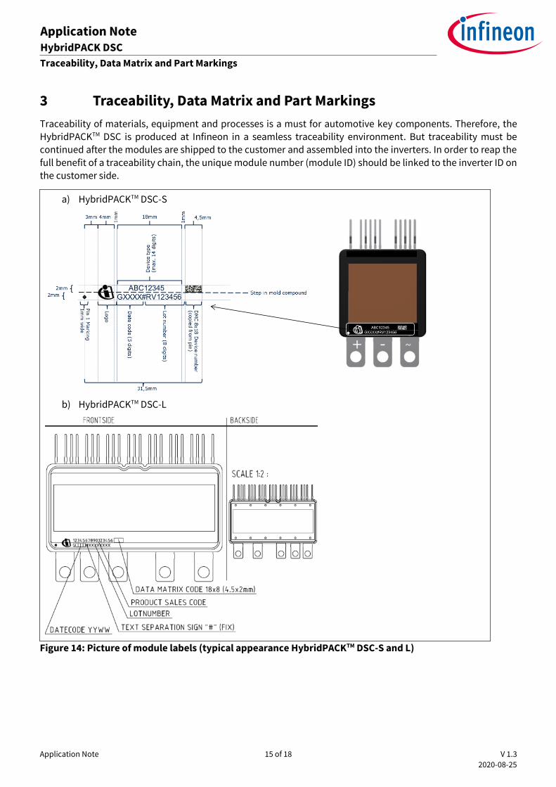
3 Traceability, Data Matrix and Part Markings
Traceability of materials, equipment and processes is a must for automotive key components. Therefore, the
HybridPACKTM DSC is produced at Infineon in a seamless traceability environment. But traceability must be continued after the modules are shipped to the customer and assembled into the inverters. In order to reap the
full benefit of a traceability chain, the unique module number (module ID) should be linked to the inverter ID on the customer side.
a) HybridPACKTM DSC-S
b) HybridPACKTM DSC-L
Figure 14: Picture of module labels (typical appearance HybridPACKTM DSC-S and L)

Application Note 16 of 18 V 1.3
2020-08-25
Application Note HybridPACK DSC
Storage and Transport
4 Storage and Transport
During transport and storage of the modules, extreme forces through shock or vibration have to be avoided as
well as extreme environmental influences.
Storage of the modules at the limits of the temperature specified in the datasheet is possible, but not recommended.
The recommended storage conditions according to IEC60721-3-1, class 1K2 should be assured for the recommended storage time of max. 2 years.
Max. air temperature: Tmaxair=+40°C
Min. air temperature: Tminair=+5°C
Max. relative humidity: 85%
Min. relative humidity: 5%
Condensation: not permissible
Precipitation: not permissible
Iceing: not permissible
Please also note that ground straps should be worn while working with the components and valid ESD safety
instructions should be followed at all time, since IGBT modules are electronic-static sensitive components. In addition, maximum permissible values in the product datasheet and application notes are absolute limits
which generally, even for short times, may not be exceeded as this may lead to destruction of the component. Moreover, this application note cannot cover every type of application and condition. Hence, the application
note cannot replace a detailed evaluation and examination by yourself or your technical divisions of the suitability for the targeted applications. The application note will, therefore, under no circumstances become
part of any supplier agreed warranty, unless the supply agreement determines otherwise in writing.

Application Note 17 of 18 V 1.3
2020-08-25
Application Note HybridPACK DSC
Storage and Transport
Revision history
Document
version Date Changed by Description of changes
0.1 01.2016 Initial version of application note
1.0 21.09.2017 Y.Inpil Renewed application note with new Following topics are
combined in this new application note
- mounting instruction
1.2 22.01.2019 A.Thomas p.16 added Figure 13 regarding the applied thermal
compound picture
overall document modified to simplify the assembly
understanding
1.3 25.08.2020 A.Thomas p.4 Table1 thermal grease recommendations
p.5 Thermal Paste Pattern added

Trademarks All referenced product or service names and trademarks are the property of their respective owners.
Edition 2020-08-25
AN-HPDSC-Assembly instructions on HybridPACK DSC
Published by
Infineon Technologies AG
81726 Munich, Germany
© 2020 Infineon Technologies AG.
All Rights Reserved.
Do you have a question about this
document?
Email: [email protected]
Document reference
IMPORTANT NOTICE The information contained in this application note is given as a hint for the implementation of the product only and shall in no event be regarded as a description or warranty of a certain functionality, condition or quality of the product. Before implementation of the product, the recipient of this application note must verify any function and other technical information given herein in the real application. Infineon Technologies hereby disclaims any and all warranties and liabilities of any kind (including without limitation warranties of non-infringement of intellectual property rights of any third party) with respect to any and all information given in this application note. The data contained in this document is exclusively intended for technically trained staff. It is the responsibility of customer’s technical departments to evaluate the suitability of the product for the intended application and the completeness of the product information given in this document with respect to such application.
For further information on the product, technology, delivery terms and conditions and prices please contact your nearest Infineon Technologies office (www.infineon.com). Please note that this product is not qualified according to the AEC Q100 or AEC Q101 documents of the Automotive Electronics Council.
WARNINGS Due to technical requirements products may contain dangerous substances. For information on the types in question please contact your nearest Infineon Technologies office. Except as otherwise explicitly approved by Infineon Technologies in a written document signed by authorized representatives of Infineon Technologies, Infineon Technologies’ products may not be used in any applications where a failure of the product or any consequences of the use thereof can reasonably be expected to result in personal injury.