an extension of eurocode 4 method to c90/105 concrete · pdf filean extension of eurocode 4...
TRANSCRIPT

BC4:2015
An Extension of Eurocode 4 Method to C90/105 Concrete and S550 Steel

i
BC4: 2015
Design Guide for Concrete Filled Tubular Members with High Strength Materials - An Extension of Eurocode 4 Method to C90/105 Concrete and S550 Steel
DESIGN GUIDE FOR CONCRETE FILLED TUBULAR MEMBERS WITH HIGH STRENGTH MATERIALS BC4:2015

ii
NOTE
1. Whilst every effort has been made to ensure accuracy of the information contained in this design guide, the Building and Construction Authority (“BCA”) makes no representations or warranty as to the completeness or accuracy thereof. Information in this design guide is supplied on the condition that the user of this publication will make their own determination as to the suitability for his or her purpose(s) prior to its use. The user of this publication must review and modify as necessary the information prior to using or incorporating the information into any project or endeavour. Any risk associated with using or relying on the information contained in the design guide shall be borne by the user. The information in the design guide is provided on an “as is” basis without any warranty of any kind whatsoever or accompanying services or support.
2. Nothing contained in this design guide is to be construed as a recommendation or requirement to use any policy, material, product, process, system or application and BCA makes no representation or warranty express or implied. NO REPRESENTATION OR WARRANTY, EITHER EXPRESSED OR IMPLIED OF FITNESS FOR A PARTICULAR PURPOSE IS MADE HEREUNDER WITH RESPECT TO INCLUDING BUT NOT LIMITED, WARRANTIES AS TO ACCURACY, TIMELINES, COMPLETENESS, MERCHANTABILITY OR FITNESS FOR A PARTICULAR PURPOSE OR COMPLIANCE WITH A PARTICULAR DESCRIPTION OR ANY IMPLIED WARRANTY ARISING FROM THE COURSE OF PERFORMANCE, COURSE OF DEALING, USAGE OF TRADE OR OTHERWISE, TO THE FULLEST EXTENT PERMITTED BY LAW. In particular, BCA makes no warranty that the information contained in the design guide will meet the user’s requirements or is error-free or that all errors in the drawings can be corrected or that the drawings will be in a form or format required by the user.
3. In no event will BCA be responsible or liable for damages of any kind resulting from the use or reliance upon information or the policies, materials, products, systems or applications to which the information refers. In addition to and notwithstanding the foregoing, in no event shall BCA be liable for any consequential or special damages or for any loss of profits incurred by the user or any third party in connection with or arising out of use or reliance of this design guide.
DESIGN GUIDE FOR CONCRETE FILLED TUBULAR MEMBERS WITH HIGH STRENGTH MATERIALS BC4:2015

iii
Copyright @ 2015 Building and Construction Authority, Singapore. All rights reserved. This document or any part thereof may not be reproduced for any reason whatsoever in any form or means whatsoever and howsoever without the prior written consent and approval of the Building and Construction Authority. Whilst every effort has been made to ensure the accuracy of the information contained in this publication, the Building and Construction Authority, its employees or agents shall not be responsible for any mistake or inaccuracy that may be contained herein and all such liability and responsibility are expressly disclaimed by these said parties.
DESIGN GUIDE FOR CONCRETE FILLED TUBULAR MEMBERS WITH HIGH STRENGTH MATERIALS BC4:2015

iv
Table of Contents
Foreword ................................................................................................................................... vi
Acknowledgement .................................................................................................................... vii
1 General ............................................................................................................................... 1
2 Materials ............................................................................................................................. 3
2.1 Concrete ....................................................................................................................... 3
2.2 Steel .............................................................................................................................. 4
2.3 Reinforcing Steel .......................................................................................................... 5
2.4 Shear Connector ........................................................................................................... 5
2.5 Material Compatibility.................................................................................................. 6
3 Design of Concrete Filled Steel Tubular Members ............................................................. 8
3.1 Local Buckling ............................................................................................................... 8
3.2 Resistance of Cross Section .......................................................................................... 8
3.2.1 Resistance to Compression .................................................................................. 8 3.2.2 Resistance to Shear Forces ................................................................................... 9 3.2.3 Resistance to Combined Compression and Bending .......................................... 10
3.3 Resistance of Members .............................................................................................. 11
3.3.1 Resistance to Compression ................................................................................ 11 3.3.2 Resistance to Combined Compression and Uniaxial Bending ............................ 14 3.3.3 Resistance to Combined Compression and Biaxial Bending .............................. 16
3.4 Longitudinal Shear ...................................................................................................... 17
3.5 Load Introduction ....................................................................................................... 18
4 Connection Detailing ........................................................................................................ 20
4.1 General ....................................................................................................................... 20
4.2 Column Splices ........................................................................................................... 20
4.3 Steel Beam to Column Joints ...................................................................................... 21
4.3.1 Simple Connections ............................................................................................ 21 4.3.2 Moment Connections ......................................................................................... 23
4.4 Concrete Beam to Column Joints ............................................................................... 27
4.4.1 Simple Connections ............................................................................................ 27 4.4.2 Moment Connections ......................................................................................... 28
4.5 Column Base ............................................................................................................... 29
DESIGN GUIDE FOR CONCRETE FILLED TUBULAR MEMBERS WITH HIGH STRENGTH MATERIALS BC4:2015
v
4.5.1 Simple Connections ............................................................................................ 29 4.5.2 Moment-Resisting Column Base Connections ................................................... 29
5 Special Considerations for High Strength Materials......................................................... 32
5.1 Fire Resistance of Concrete Filled Tubular Members ................................................ 32
5.2 Fabrication of High Tensile Steel Sections ................................................................. 33
5.3 Preparation of High Strength Concrete ...................................................................... 35
5.4 Casting of Concrete in Steel Tubes ............................................................................. 36
5.5 Differential Column Shortening ................................................................................. 37
References ................................................................................................................................ 38
Appendix A Design Flowchart .................................................................................................. 40
A.1 Design for Concrete Filled Steel Tubular Column Subject to Axial Force Only .............. 40
A.2 Design for Concrete Filled Steel Tubular Column Subject to Combined Axial Force and Bending Moments ................................................................................................................ 41
DESIGN GUIDE FOR CONCRETE FILLED TUBULAR MEMBERS WITH HIGH STRENGTH MATERIALS BC4:2015

vi
Foreword
Concrete filled steel tubular members, comprising a hollow steel tube infilled with concrete, have been used in many structural applications, especially for columns in high rise buildings and bridge piers. The other applications include structural uses in civil infrastructural work, industrial construction, offshore oil and gas installations and protective structures. Although a series of design guides on concrete filled steel tubular members have been produced by the American, Chinese, Europe, and Japanese codes as well as by CIDECT guide (International Committee for the Development and study of Tubular Structures), they do not provide additional guidelines on the use of high strength concrete and high tensile steel.
This design guide is based on Eurocode 4 for the design of concrete filled steel tubular members with special considerations for higher concrete strength with cylinder compressive strength up to 90N/mm2 and higher grade of steel with yield strength up to 550N/mm2. More than 2000 test data collected from the literature on concrete filled steel tubes with normal and high strength materials have been analysed to formulate the design method proposed in this design guide.
This design guide also provides good detailing practices for typical joints between concrete filled tubular members and other structural components. Guideline is provided to select matching concrete and steel grades for the design of high strength concrete filled columns. Special considerations for fire resistance design, fabrication of high tensile steel sections, and preparation of high strength concrete are emphasized. This design guide will endow structural engineers with the confidence to use high strength materials in a safe and economic manner to design and construct high rise buildings.
This Guidebook is a concise version of the book on design guide for Concrete Filled Tubular Members with High Strength Materials by Liew and Xiong (2015) including detailed guides on the use of high strength steel and high strength concrete materials, test database and work examples.
DESIGN GUIDE FOR CONCRETE FILLED TUBULAR MEMBERS WITH HIGH STRENGTH MATERIALS BC4:2015

vii
Acknowledgement
The Building and Construction Authority of Singapore (BCA) would like to thank the authors for developing this Guidebook as well as the local and international expert committee members for their valuable contributions.
Authors
Prof. Richard Liew, National University of Singapore (Author) Dr. Mingxiang Xiong, National University of Singapore (Co-author) Dr. Chi Trung Tran, Building and Construction Authority (Co-author)
Members of the Expert Committee
Prof. Sing Ping Chiew, Singapore Institute of Technology Mr. Thanabal Kaliannan, Singapore Structural Steel Society A/Prof. Sze Dai Pang, National University of Singapore Dr. Tongyun Wang, National University of Singapore Dr. Dexin Xiong, National University of Singapore Prof. Reidar Bjorhovde, The Bjorhovde Group, USA Prof. Siu Lai Chan, Hong Kong Polytechnic University, Hong Kong Prof. Yong Du, Nanjing Tech University, China Prof. Lin Hai Han, Tsinghua University, China Dr. Hisaya Kamura, JFE Steel Corporation, Japan Prof. Akihiko Kawano, Kyushu University, Japan Prof. Dennis Lam, University of Bradford, UK Prof. Guo Qiang Li, Tongji University, China Mr. Takayuki Nanba, JFE Steel Corporation, Japan Prof. David A Nethercot, Imperial College London, UK Prof. Keigo Tsuda, University of Kitakyushu, Japan Prof. Brian Uy, University of New South Wales, Australia Prof. Yong Wang, The University of Manchester, UK Prof. Ben Young, The University of Hong Kong, Hong Kong
DESIGN GUIDE FOR CONCRETE FILLED TUBULAR MEMBERS WITH HIGH STRENGTH MATERIALS BC4:2015

1
1 General
(1) This design guide is applicable for design of concrete filled steel tubular members with concrete cylinder strength up to 90N/mm2 and steel of yield strength up to 550N/mm2.
(2) This design guide is based on EN 1994-1-1 and EN 1994-1-2 for the design of concrete filled steel tubular members with special considerations for the high strength concrete and the high tensile steel.
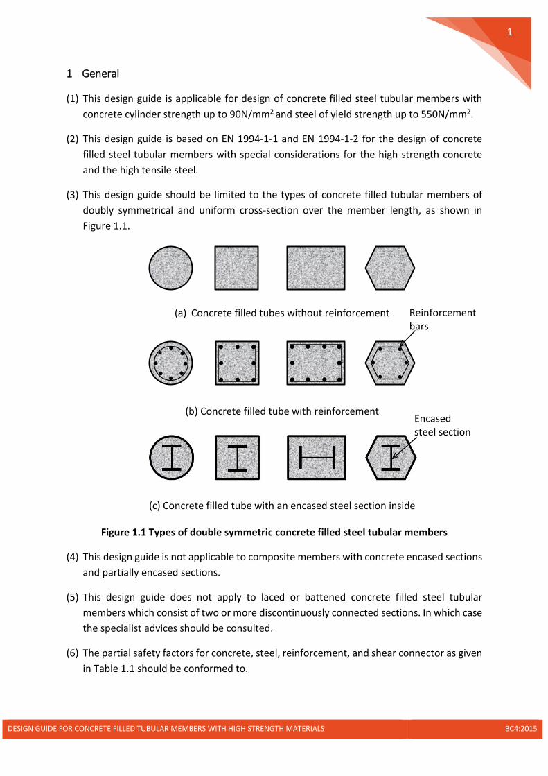
(3) This design guide should be limited to the types of concrete filled tubular members of doubly symmetrical and uniform cross-section over the member length, as shown in Figure 1.1.
(a) Concrete filled tubes without reinforcement
(b) Concrete filled tube with reinforcement
(c) Concrete filled tube with an encased steel section inside
Figure 1.1 Types of double symmetric concrete filled steel tubular members
(4) This design guide is not applicable to composite members with concrete encased sections and partially encased sections.
(5) This design guide does not apply to laced or battened concrete filled steel tubular members which consist of two or more discontinuously connected sections. In which case the specialist advices should be consulted.
(6) The partial safety factors for concrete, steel, reinforcement, and shear connector as given in Table 1.1 should be conformed to.
Encased steel section
Reinforcement bars
DESIGN GUIDE FOR CONCRETE FILLED TUBULAR MEMBERS WITH HIGH STRENGTH MATERIALS BC4:2015

2
Table 1.1 Partial safety factors of materials
Concrete Steel Reinforcement Shear Connector
γ𝑐𝑐 = 1.5 γ𝑎𝑎 = 1.0 γ𝑠𝑠 = 1.15 γ𝑣𝑣 = 1.25
(7) The ratio of the depth to the width of the composite cross-section should be within the limits of 0.2 and 5.0.
(8) The longitudinal reinforcements that may be used in calculation should not exceed 6% of the concrete area. The longitudinal reinforcements in concrete filled tube may not be necessary if they are not required for fire resistance.
(9) The steel contribution ratio, defined in Eq.(1.1), should fulfill the condition in Eq. (1.2).
,
a yd e ed
pl Rd
A f A fN
δ+
= (1.1)
where
𝐴𝐴𝑎𝑎,𝐴𝐴𝑒𝑒 are the cross-sectional area of steel tube and encased steel section, respectively
𝑓𝑓𝑦𝑦𝑦𝑦 ,𝑓𝑓𝑒𝑒𝑦𝑦 are the design strength of steel tube and encased steel section, respectively
𝑁𝑁𝑝𝑝𝑝𝑝,𝑅𝑅𝑦𝑦 is the axial resistance of composite section
The range of the steel contribution should be
0.2 0.9δ≤ ≤ (1.2)
(10) The general method given in EN 1994-1-1 is applicable to the concrete filled steel tubular members with high strength materials. The general method may be implemented by means of advanced finite element analysis.
DESIGN GUIDE FOR CONCRETE FILLED TUBULAR MEMBERS WITH HIGH STRENGTH MATERIALS BC4:2015
3
2 Materials
2.1 Concrete
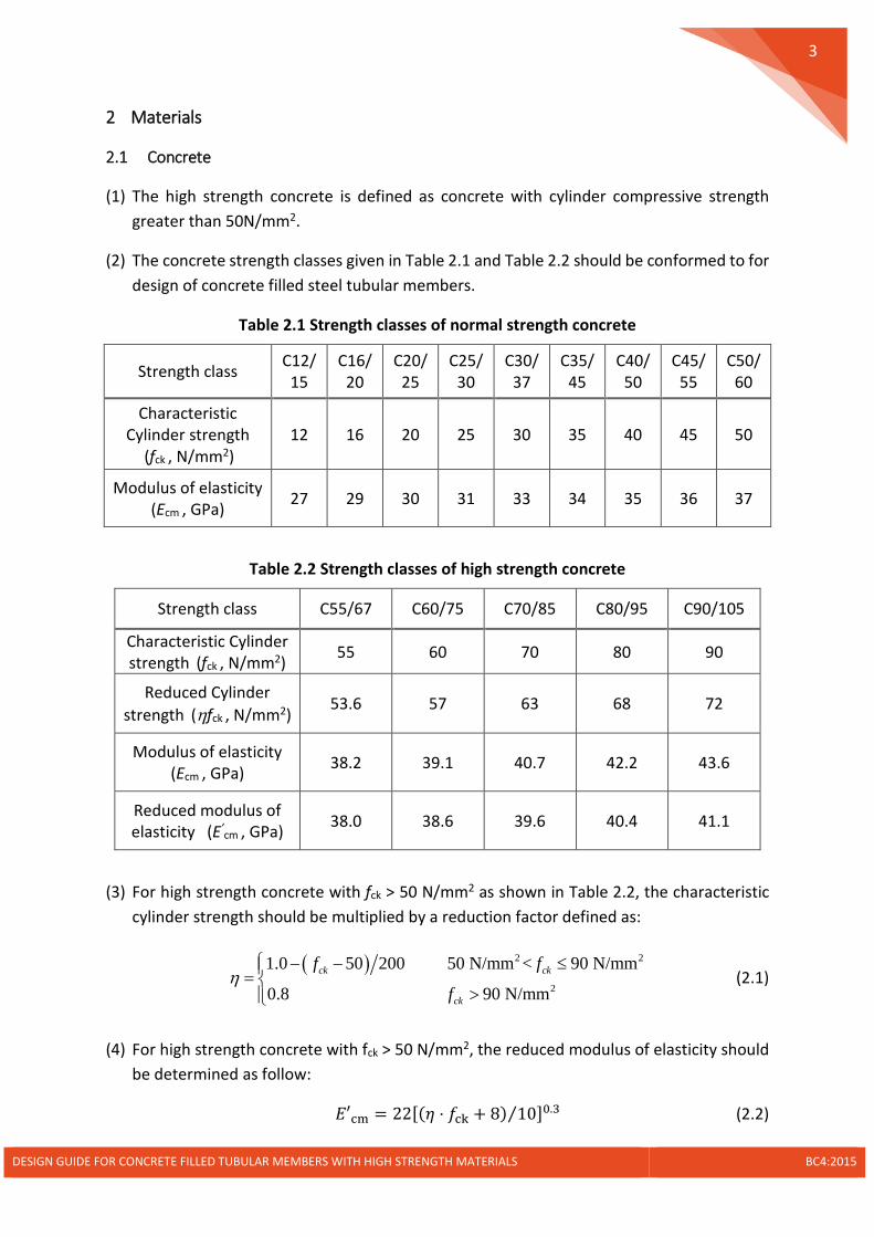
(1) The high strength concrete is defined as concrete with cylinder compressive strength greater than 50N/mm2.
(2) The concrete strength classes given in Table 2.1 and Table 2.2 should be conformed to for design of concrete filled steel tubular members.
Table 2.1 Strength classes of normal strength concrete
Strength class C12/15
C16/20
C20/25
C25/30
C30/37
C35/45
C40/50
C45/55
C50/60
Characteristic Cylinder strength
(fck , N/mm2) 12 16 20 25 30 35 40 45 50
Modulus of elasticity (Ecm , GPa) 27 29 30 31 33 34 35 36 37
Table 2.2 Strength classes of high strength concrete
Strength class C55/67 C60/75 C70/85 C80/95 C90/105
Characteristic Cylinder strength (fck , N/mm2) 55 60 70 80 90
Reduced Cylinder strength (ηfck , N/mm2)
53.6 57 63 68 72
Modulus of elasticity (Ecm , GPa) 38.2 39.1 40.7 42.2 43.6
Reduced modulus of elasticity (E’cm , GPa) 38.0 38.6 39.6 40.4 41.1
(3) For high strength concrete with fck > 50 N/mm2 as shown in Table 2.2, the characteristic cylinder strength should be multiplied by a reduction factor defined as:
( ) 2 2
2
1.0 50 200 50 N/mm < 90 N/mm
0.8 90 N/mmck ck
ck
f f
fη
− − ≤= >
(2.1)
(4) For high strength concrete with fck > 50 N/mm2, the reduced modulus of elasticity should be determined as follow:
𝐸𝐸′cm = 22[(𝜂𝜂 ⋅ 𝑓𝑓ck + 8) 10⁄ ]0.3 (2.2)
DESIGN GUIDE FOR CONCRETE FILLED TUBULAR MEMBERS WITH HIGH STRENGTH MATERIALS BC4:2015
4
2.2 Steel
(1) The steel with yield strength higher than 460N/mm2 is defined as high tensile steel.
(2) The technical delivery conditions for flat products of high strength quenched and tempered steels should conform to EN 10025-6.
(3) The technical delivery conditions of high tensile steel plates manufactured from thermo-mechanically controlled process should comply with EN 10149-2.
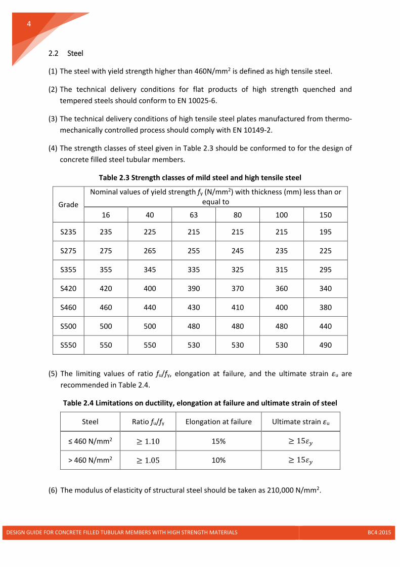
(4) The strength classes of steel given in Table 2.3 should be conformed to for the design of concrete filled steel tubular members.
Table 2.3 Strength classes of mild steel and high tensile steel
Grade
Nominal values of yield strength fy (N/mm2) with thickness (mm) less than or equal to
16 40 63 80 100 150
S235 235 225 215 215 215 195
S275 275 265 255 245 235 225
S355 355 345 335 325 315 295
S420 420 400 390 370 360 340
S460 460 440 430 410 400 380
S500 500 500 480 480 480 440
S550 550 550 530 530 530 490
(5) The limiting values of ratio fu/fy, elongation at failure, and the ultimate strain εu are recommended in Table 2.4.
Table 2.4 Limitations on ductility, elongation at failure and ultimate strain of steel
Steel Ratio fu/fy Elongation at failure Ultimate strain εu
≤ 460 N/mm2 ≥ 1.10 15% ≥ 15𝜀𝜀𝑦𝑦
> 460 N/mm2 ≥ 1.05 10% ≥ 15𝜀𝜀𝑦𝑦
(6) The modulus of elasticity of structural steel should be taken as 210,000 N/mm2.
DESIGN GUIDE FOR CONCRETE FILLED TUBULAR MEMBERS WITH HIGH STRENGTH MATERIALS BC4:2015

5
(7) The maximum permissible plate thickness for mild steel and high tensile steel should be determined in accordance with EN 1993-1-10 and EN 1993-1-12, respectively.
(8) For the structural steel materials to be used in Singapore, they should be in compliance with BC1:2012.
2.3 Reinforcing Steel
(1) The yield strength of reinforcing steel should be limited to the range of 400 N/mm2 to 600 N/mm2 as conforming to EN 1992-1-1.
(2) The strength classes of reinforcing steel provided in Table 2.5 can be used in the concrete filled steel tubular members.
Table 2.5 Strength classes of reinforcing steel
Class Characteristic yield strength (fyk, N/mm2)
Ultimate/yield strength ratio
Ultimate elongation
B500A 500 1.05 2.5%
B500B 500 1.08 5.0%
B500C 500 ≥ 1.15, < 1.35 7.5%
(3) The elastic modulus of reinforcing steel should be taken as 210,000 N/mm2.
(4) The Grade 460 reinforcing steel is allowed in accordance with BS 4449.
2.4 Shear Connector
(1) The mechanical characteristics and nominal dimensions of shear studs should conform to BS EN ISO 13918 and BS EN ISO 898-1.
(2) Weldability and welding examination of shear studs should be checked in accordance with BS EN ISO 14555.
(3) High strength concrete provides higher confinement for shear studs locally. The design shear resistance of a headed stud, irrespective of concrete strength, may be calculated according to Eq.(2.3):
22 0.290.8min ,4
s s ck cmus sRd
v v
d f Ef dPαπ
γ γ
=
(2.3)
where
DESIGN GUIDE FOR CONCRETE FILLED TUBULAR MEMBERS WITH HIGH STRENGTH MATERIALS BC4:2015

6
𝑑𝑑𝑠𝑠 is the diameter of the shank of the shear stud, 16mm ≤ 𝑑𝑑𝑠𝑠 ≤ 25mm
𝑓𝑓𝑢𝑢𝑠𝑠 is the ultimate strength of the shear stud, ≤ 500N/mm2
ℎ𝑠𝑠𝑐𝑐 Is the overall height of the shear stud
𝛾𝛾𝑣𝑣 is the partial factor which is 1.25 for the ultimate limit state
𝛼𝛼𝑠𝑠 = 0.2 �ℎ𝑠𝑠𝑠𝑠𝑦𝑦𝑠𝑠
+ 1� for 3 ≤ ℎ𝑠𝑠𝑐𝑐 ≤ 4
1.0 for ℎ𝑠𝑠𝑐𝑐 > 4
(4) For applications in Singapore, shear studs not covered in this design guide shall be allowed
provided they are in compliance with the provisions in BC1:2012.
(5) Shear connectors other than the stud type, such as weld beads, welded reinforcements, welded shear keys, etc., are allowed provided they can perform in accordance with the product manufacturer’s recommendations or when specialist’s advice is consulted.
2.5 Material Compatibility
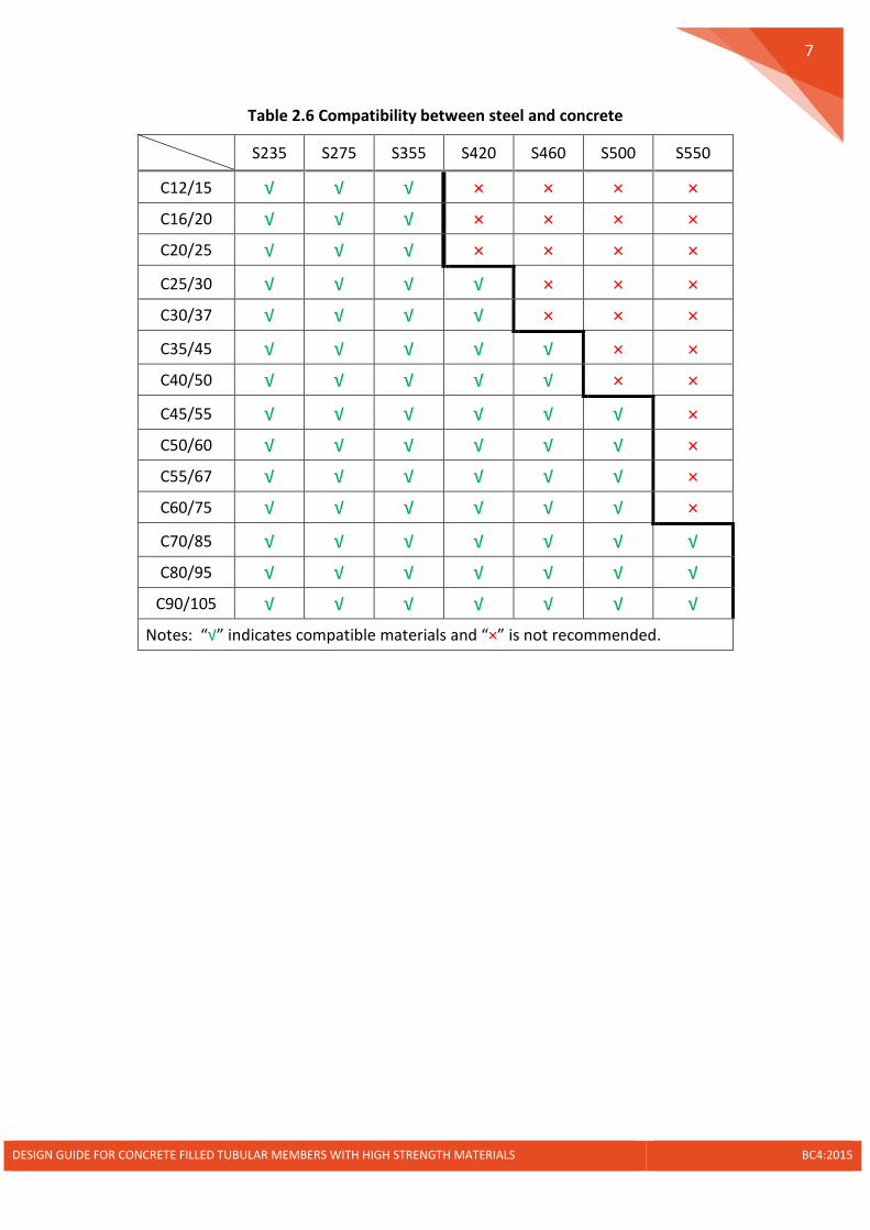
(6) For structural steel and concrete used in the concrete filled tubular members, the material compatibility recommended in Table 2.6 should be conformed to.
(7) Alternatively, the maximum steel strength should be determined in accordance with the concrete characteristic cylinder strength with class up to C90/105 using the following expression:
( )0.310.7 8y a ckf E f≤ + (2.4)
where
fy is the characteristic yield strength of steel
Ea is the modulus of Elasticity of steel
fck is the characteristic cylinder strength of concrete
DESIGN GUIDE FOR CONCRETE FILLED TUBULAR MEMBERS WITH HIGH STRENGTH MATERIALS BC4:2015
7
Table 2.6 Compatibility between steel and concrete
S235 S275 S355 S420 S460 S500 S550
C12/15 √ √ √ × × × × C16/20 √ √ √ × × × × C20/25 √ √ √ × × × ×
C25/30 √ √ √ √ × × × C30/37 √ √ √ √ × × ×
C35/45 √ √ √ √ √ × × C40/50 √ √ √ √ √ × ×
C45/55 √ √ √ √ √ √ × C50/60 √ √ √ √ √ √ × C55/67 √ √ √ √ √ √ × C60/75 √ √ √ √ √ √ ×
C70/85 √ √ √ √ √ √ √ C80/95 √ √ √ √ √ √ √
C90/105 √ √ √ √ √ √ √ Notes: “√” indicates compatible materials and “×” is not recommended.
DESIGN GUIDE FOR CONCRETE FILLED TUBULAR MEMBERS WITH HIGH STRENGTH MATERIALS BC4:2015

8
3 Design of Concrete Filled Steel Tubular Members
3.1 Local Buckling
(1) The effects of local buckling may be neglected for the steel section fully encased by the concrete inside the steel tubular members. For the outer tube, the maximum value of Table 3.1 should not be exceeded.
Table 3.1 Maximum values (d/t), (h/t) for local buckling
Concrete filled Cross-section
Maximum value in expressions
Maximum values according to steel grades
S275 S355 S460 S500 S550
( )max
23590
y
dt f
= 77 60 46 42 38
( )max
23552
y
ht f
= 48 42 37 35 34
(2) The local buckling of the outer steel section may be prevented by increasing the plate thickness. Alternatively, stiffener plate may be welded on the steel plate along the longitudinal direction of the column to reduce the effective width of the steel plate.
3.2 Resistance of Cross Section
3.2.1 Resistance to Compression
(1) The plastic design resistance to compression of a concrete filled tubular section with an encased steel section inside (refer to Figure 1.1(c)) should be calculated by adding the plastic resistances of its components:
, a c s epl Rd yd cd sd edN A f A f A f A f= + + + (3.1)
where
𝐴𝐴𝑎𝑎,𝐴𝐴𝑐𝑐,𝐴𝐴𝑠𝑠,𝐴𝐴𝑒𝑒 are the cross-sectional area of steel tube, concrete, reinforcements and encased steel section, respectively
𝑓𝑓𝑦𝑦𝑦𝑦 ,𝑓𝑓𝑐𝑐𝑦𝑦 ,𝑓𝑓𝑠𝑠𝑦𝑦 , 𝑓𝑓𝑒𝑒𝑦𝑦 are the design strength of steel tube, concrete, reinforcements and encased steel section, respectively
dt
ht
DESIGN GUIDE FOR CONCRETE FILLED TUBULAR MEMBERS WITH HIGH STRENGTH MATERIALS BC4:2015
9
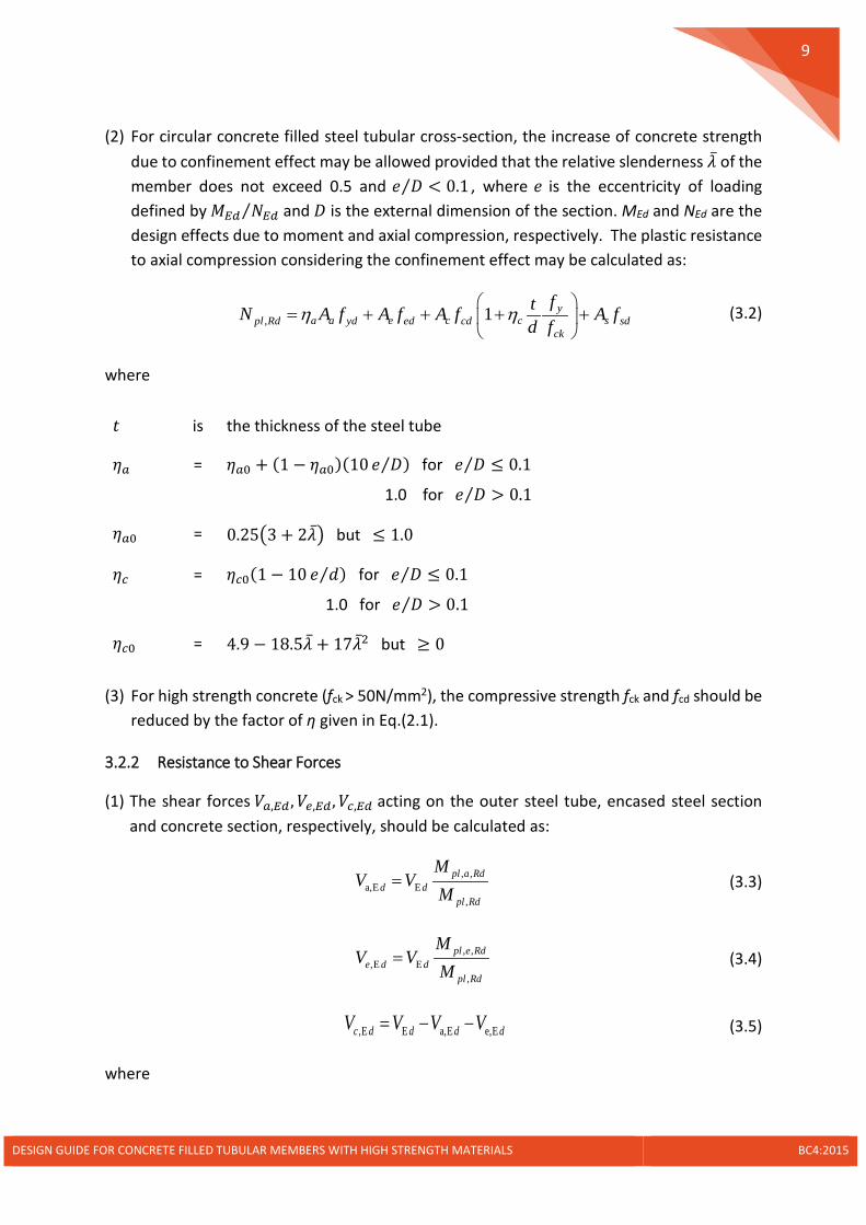
(2) For circular concrete filled steel tubular cross-section, the increase of concrete strength
due to confinement effect may be allowed provided that the relative slenderness �̅�𝜆 of the member does not exceed 0.5 and 𝑒𝑒 𝐷𝐷⁄ < 0.1 , where 𝑒𝑒 is the eccentricity of loading defined by 𝑀𝑀𝐸𝐸𝑦𝑦 𝑁𝑁𝐸𝐸𝑦𝑦⁄ and 𝐷𝐷 is the external dimension of the section. MEd and NEd are the design effects due to moment and axial compression, respectively. The plastic resistance to axial compression considering the confinement effect may be calculated as:
, 1 ya a e c c spl Rd yd ed cd sd
ck
ftN A f A f A f A fd f
η η
= + + + + (3.2)
where
𝑡𝑡 is the thickness of the steel tube
𝜂𝜂𝑎𝑎 = 𝜂𝜂𝑎𝑎0 + (1 − 𝜂𝜂𝑎𝑎0)(10 𝑒𝑒 𝐷𝐷⁄ ) for 𝑒𝑒 𝐷𝐷⁄ ≤ 0.1
1.0 for 𝑒𝑒 𝐷𝐷⁄ > 0.1
𝜂𝜂𝑎𝑎0 = 0.25�3 + 2�̅�𝜆� but ≤ 1.0
𝜂𝜂𝑐𝑐 = 𝜂𝜂𝑐𝑐0(1 − 10 𝑒𝑒 𝑑𝑑⁄ ) for 𝑒𝑒 𝐷𝐷⁄ ≤ 0.1
1.0 for 𝑒𝑒 𝐷𝐷⁄ > 0.1
𝜂𝜂𝑐𝑐0 = 4.9 − 18.5�̅�𝜆 + 17�̅�𝜆2 but ≥ 0
(3) For high strength concrete (fck > 50N/mm2), the compressive strength fck and fcd should be
reduced by the factor of η given in Eq.(2.1).
3.2.2 Resistance to Shear Forces
(1) The shear forces 𝑉𝑉𝑎𝑎,𝐸𝐸𝑦𝑦 ,𝑉𝑉𝑒𝑒,𝐸𝐸𝑦𝑦,𝑉𝑉𝑐𝑐,𝐸𝐸𝑦𝑦 acting on the outer steel tube, encased steel section and concrete section, respectively, should be calculated as:
, ,a,E E
,
pl a Rdd d
pl Rd
MV V
M= (3.3)
, ,,E E
,
pl e Rde d d
pl Rd
MV V
M= (3.4)
,E E a,E e,Ec d d d dV V V V= − − (3.5)
where
DESIGN GUIDE FOR CONCRETE FILLED TUBULAR MEMBERS WITH HIGH STRENGTH MATERIALS BC4:2015
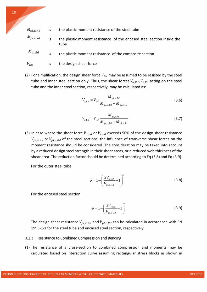
10
𝑀𝑀𝑝𝑝𝑝𝑝,𝑎𝑎,𝑅𝑅𝑦𝑦 is the plastic moment resistance of the steel tube
𝑀𝑀𝑝𝑝𝑝𝑝,𝑒𝑒,𝑅𝑅𝑦𝑦 is the plastic moment resistance of the encased steel section inside the tube
𝑀𝑀𝑝𝑝𝑝𝑝,𝑅𝑅𝑦𝑦 is the plastic moment resistance of the composite section
𝑉𝑉𝐸𝐸𝑦𝑦 is the design shear force (2) For simplification, the design shear force 𝑉𝑉𝐸𝐸𝑦𝑦 may be assumed to be resisted by the steel
tube and inner steel section only. Thus, the shear forces 𝑉𝑉𝑎𝑎,𝐸𝐸𝑦𝑦,𝑉𝑉𝑒𝑒,𝐸𝐸𝑦𝑦 acting on the steel tube and the inner steel section, respectively, may be calculated as:
, ,a,E E
, , ,e,
pl a Rdd d
pl a Rd pl Rd
MV V
M M=
+ (3.6)
, ,,E E
, , , ,
pl e Rde d d
pl a Rd pl e Rd
MV V
M M=
+ (3.7)
(3) In case where the shear force 𝑉𝑉𝑎𝑎,𝐸𝐸𝑦𝑦 or 𝑉𝑉𝑒𝑒,𝐸𝐸𝑦𝑦 exceeds 50% of the design shear resistance 𝑉𝑉𝑝𝑝𝑝𝑝,𝑎𝑎,𝑅𝑅𝑦𝑦 or 𝑉𝑉𝑝𝑝𝑝𝑝,𝑒𝑒,𝑅𝑅𝑦𝑦 of the steel sections, the influence of transverse shear forces on the moment resistance should be considered. The consideration may be taken into account by a reduced design steel strength in their shear areas, or a reduced web thickness of the shear area. The reduction factor should be determined according to Eq.(3.8) and Eq.(3.9).
For the outer steel tube
2
a,E
pl,a,E
21 1d
d
VV
φ
= − −
(3.8)
For the encased steel section
2
e,E
pl,e,E
21 1d
d
VV
φ
= − −
(3.9)
The design shear resistance 𝑉𝑉𝑝𝑝𝑝𝑝,𝑎𝑎,𝑅𝑅𝑦𝑦 and 𝑉𝑉𝑝𝑝𝑝𝑝,𝑒𝑒,𝑅𝑅𝑦𝑦 can be calculated in accordance with EN 1993-1-1 for the steel tube and encased steel section, respectively.
3.2.3 Resistance to Combined Compression and Bending
(1) The resistance of a cross-section to combined compression and moments may be calculated based on interaction curve assuming rectangular stress blocks as shown in
DESIGN GUIDE FOR CONCRETE FILLED TUBULAR MEMBERS WITH HIGH STRENGTH MATERIALS BC4:2015
11
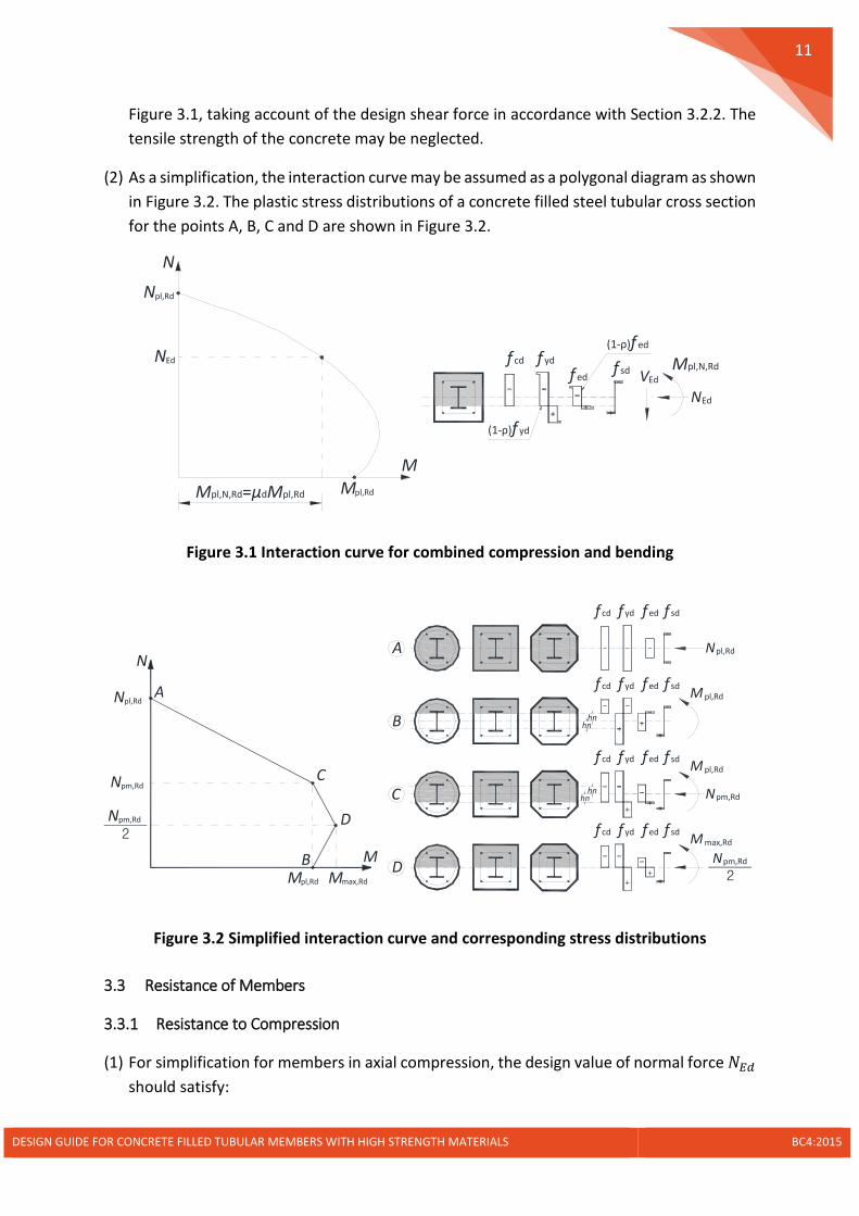
Figure 3.1, taking account of the design shear force in accordance with Section 3.2.2. The tensile strength of the concrete may be neglected.
(2) As a simplification, the interaction curve may be assumed as a polygonal diagram as shown in Figure 3.2. The plastic stress distributions of a concrete filled steel tubular cross section for the points A, B, C and D are shown in Figure 3.2.
Figure 3.1 Interaction curve for combined compression and bending
Figure 3.2 Simplified interaction curve and corresponding stress distributions
3.3 Resistance of Members
3.3.1 Resistance to Compression
(1) For simplification for members in axial compression, the design value of normal force 𝑁𝑁𝐸𝐸𝑦𝑦 should satisfy:
NEd
Npl,Rd
Mpl,Rd
N
M
Mpl,N,RdVEd
f yd
f edf sd
(1-ρ)f yd
(1-ρ)f ed
NEd
Mpl,N,Rd=μdMpl,Rd
f cd
Npm,Rd
Npl,Rd
Mpl,Rd Mmax,Rd
N
M
A
C
D
B
Npl,Rd
hnhn
Npm,Rdhn
hn
M max,Rd
M pl,Rd
M pl,Rd
Npm,Rd
2
Npm,Rd
2
A
B
C
D
f cd f yd f ed f sd
f cd f yd f ed f sd
f cd f yd f ed f sd
f cd f yd f ed f sd
DESIGN GUIDE FOR CONCRETE FILLED TUBULAR MEMBERS WITH HIGH STRENGTH MATERIALS BC4:2015

12
,
1Ed
pl Rd
NNχ
≤ (3.10)
(2) The value of 𝜒𝜒 for the appropriate non-dimensional slenderness �̅�𝜆 should be determined from the relevant buckling curve according to:
22
1χλ
=Φ + Φ −
but 1χ ≤ (3.11)
where
Φ = 0.5�1 + 𝛼𝛼��̅�𝜆 − 0.2� + �̅�𝜆2�
𝛼𝛼 = the imperfection factor as given in Table 3.2, the relevant buckling curves and member imperfections are given in Table 3.3
�̅�𝜆 = the relative slenderness for the plane of bending and equal to�𝑁𝑁𝑝𝑝𝑝𝑝,𝑅𝑅𝑅𝑅𝑁𝑁𝑠𝑠𝑐𝑐
𝑁𝑁𝑝𝑝𝑝𝑝,𝑅𝑅𝑅𝑅 = the characteristic value of the plastic resistance to compression 𝑁𝑁𝑝𝑝𝑝𝑝,𝑅𝑅𝑦𝑦 in which the material characteristic strengths rather than the design strength should be used.
𝑁𝑁𝑐𝑐𝑐𝑐 = the elastic critical normal force for the relevant buckling mode determined by Eq. 3.12.
(3) The elastic critical normal force 𝑁𝑁𝑐𝑐𝑐𝑐 for the relevant buckling mode is determined by:
( )2
2eff
creff
EIN
L
π= (3.12)
where
𝐿𝐿eff is the buckling length of a composite column for the relevant buckling mode. In the absence of Eurocode guidance, method to calculate the effective buckling lengths given in BS 5950: Part 1 may be adopted.
(4) The effective flexural stiffness of a concrete filled steel tubular section (𝐸𝐸𝐸𝐸)eff should be
determined from:
( ) 0.6a a s s e e cm ceffEI E I E I E I E I= + + + (3.13)
where
DESIGN GUIDE FOR CONCRETE FILLED TUBULAR MEMBERS WITH HIGH STRENGTH MATERIALS BC4:2015

13
𝐸𝐸𝑎𝑎, 𝐸𝐸𝑐𝑐 , 𝐸𝐸𝑠𝑠, 𝐸𝐸𝑒𝑒 are the second moments of area of the steel tube, the un-cracked concrete, the reinforcements and the encased steel section for the bending plane being considered
𝐸𝐸𝑎𝑎,𝐸𝐸𝑐𝑐𝑐𝑐,𝐸𝐸𝑠𝑠,𝐸𝐸𝑒𝑒 are the modulus of elasticity of the steel tube, the un-cracked concrete, the reinforcements and the encased steel section
(5) The influence of long-term effects on the effective flexural stiffness (𝐸𝐸𝐸𝐸)eff should be accounted for. The modulus of elasticity of concrete 𝐸𝐸cm should be reduced to the value 𝐸𝐸c,eff in accordance with the following equation:
( ),,
11 /cmc eff
tG Ed Ed
E EN N ϕ
=+
(3.14)
where
𝑁𝑁𝐺𝐺,𝐸𝐸𝑦𝑦 is the part of the normal force that is permanent
𝜑𝜑𝑡𝑡 is the creep coefficient
Table 3.2 Imperfect factors for buckling curves
Buckling curve a b
Imperfection factor 0.21 0.34
Table 3.3 Buckling curves and member imperfections for concrete filled steel tubular cross-sections
Cross section
Limits Axis of buckling Buckling curve Member
imperfection
𝜌𝜌𝑠𝑠 ≤ 3% any 𝑎𝑎 𝐿𝐿/300
𝜌𝜌𝑠𝑠 > 3% any 𝑏𝑏 𝐿𝐿/200
- any 𝑏𝑏 𝐿𝐿/200
- any 𝑏𝑏 𝐿𝐿/200
Note: ρs is the area ratio of reinforcements relative to the concrete area.
DESIGN GUIDE FOR CONCRETE FILLED TUBULAR MEMBERS WITH HIGH STRENGTH MATERIALS BC4:2015

14
(6) For simplification, the creep coefficient 𝜑𝜑𝑡𝑡 may be conservatively taken as that for normal strength concrete when high strength concrete is used. The creep coefficient 𝜑𝜑𝑡𝑡 should be determined in accordance with EN 1992-1-1.
3.3.2 Resistance to Combined Compression and Uniaxial Bending
(1) The following expression based on the interaction curve determined according to Section 3.2.3 should be satisfied:
, , ,
Ed EdM
pl N Rd d pl Rd
M MM M
αµ
= ≤ (3.15)
where
𝑀𝑀𝐸𝐸𝑦𝑦 is the greatest of the end moments and the maximum bending moment within the column length, including imperfections and second order effects
𝑀𝑀𝑝𝑝𝑝𝑝,𝑁𝑁,𝑅𝑅𝑦𝑦 is the plastic bending resistance taking into account the normal force 𝑁𝑁𝐸𝐸𝑦𝑦, given by 𝜇𝜇𝑦𝑦𝑀𝑀𝑝𝑝𝑝𝑝,𝑅𝑅𝑦𝑦
𝑀𝑀𝑝𝑝𝑝𝑝,𝑅𝑅𝑦𝑦 is the plastic bending resistance given by Point B in Section 3.2.3
𝛼𝛼𝑀𝑀 = 0.9 for steel grades S235, S275, S355
0.8 for other steel grades up to S550
(2) Within the column length, second-order effects may be allowed for by multiplying the
greatest first-order design bending moment by a factor 𝑘𝑘 given in Eq.(3.16). The second-order effect should be considered for both moments from initial member imperfection and first-order analysis as given in Figure 3.3 and calculated from Eq.(3.17).
,1 /Ed cr effk
N Nβ=
− (3.16)
where
𝛽𝛽 is an equivalent moment factor given in Table 3.4
𝑁𝑁𝑐𝑐𝑐𝑐,𝑒𝑒𝑒𝑒𝑒𝑒 is the critical normal force for the relevant axis and corresponding to the effective flexural stiffness given in Eq.(3.18), with the effective length taken as the column length
DESIGN GUIDE FOR CONCRETE FILLED TUBULAR MEMBERS WITH HIGH STRENGTH MATERIALS BC4:2015

15
(a) Moment from first-order analysis (b) Moment from imperfection
Figure 3.3 Amplifications for moments from first-order analysis and member imperfection
0 0 1 ,1 ,1 Ed Ed Ed EdM k N e k M M= + ≥ (3.17)
where
𝑀𝑀𝐸𝐸𝑦𝑦,1 is the maximum first-order design moment in column length
𝑒𝑒0 is the member imperfection, given in Table 3.3
( ) ( ),eff, 0.9 0.5a a s s e e cceff IIEI E I E I E I E I= + + + (3.18)
Table 3.4 Equivalent moment factor 𝜷𝜷
Moment distribution Moment factors 𝜷𝜷 Comment
First-order bending moment from member
imperfection or lateral load: 𝛽𝛽 = 1.0
𝑀𝑀𝐸𝐸𝑦𝑦 is the maximum
bending moment within the
column length ignoring second-
order effects
End moments: 𝛽𝛽 = 𝑚𝑚𝑎𝑎𝑚𝑚(0.44, 0.66
+ 0.44𝑟𝑟)
𝑀𝑀𝐸𝐸𝑦𝑦 and 𝑟𝑟𝑀𝑀𝐸𝐸𝑦𝑦 are the end
moments from first-order or second-order global effects
MEd,1,top
MEd,1,bot
MEd,1
k1MEd,1
MEd,1,top
MEd,1,botr=
MEd,1=max(MEd,1,top , MEd,1,top)
NEd
e0
k0NEde0β
M
M
Ed
Ed
-1≤r≤1
rMEd
MEd
DESIGN GUIDE FOR CONCRETE FILLED TUBULAR MEMBERS WITH HIGH STRENGTH MATERIALS BC4:2015

16
3.3.3 Resistance to Combined Compression and Biaxial Bending
(1) For combined compression and biaxial bending, the following conditions should be satisfied for the stability check within the column length and for the check at the column ends:
,,
, ,
y EdM y
dy pl y Rd
MM
αµ
≤ (3.19)
z,,
, ,
EdM z
dz pl z Rd
MM
αµ
≤ (3.20)
, z,
, , , ,
1y Ed Ed
dy pl y Rd dz pl z Rd
M MM Mµ µ
+ ≤ (3.21)
𝑀𝑀𝑦𝑦,𝐸𝐸𝑦𝑦,𝑀𝑀𝑧𝑧,𝐸𝐸𝑦𝑦 are the design bending moments around 𝑦𝑦 − 𝑦𝑦 or 𝑧𝑧 − 𝑧𝑧 axis including second-order effects and imperfects
𝑀𝑀𝑝𝑝𝑝𝑝,𝑦𝑦,𝑅𝑅𝑦𝑦,𝑀𝑀𝑝𝑝𝑝𝑝,𝑧𝑧,𝑅𝑅𝑦𝑦 are the plastic bending resistances around 𝑦𝑦 − 𝑦𝑦 or 𝑧𝑧 − 𝑧𝑧 axis
𝛼𝛼𝑀𝑀,𝑦𝑦,𝛼𝛼𝑀𝑀,𝑧𝑧 = 0.9 for steel grades S235, S275, S355
0.8 for other steel grades up to S550
(2) The value 𝜇𝜇𝑦𝑦 = 𝜇𝜇𝑦𝑦𝑦𝑦 𝑜𝑜𝑟𝑟 𝜇𝜇𝑦𝑦𝑧𝑧 as shown in Figure 3.4 refers to the design plastic resistance
moment 𝑀𝑀𝑝𝑝𝑝𝑝,𝑅𝑅𝑦𝑦 for the plane of bending being considered. Values 𝜇𝜇𝑦𝑦 greater than 1.0 should only be used where the bending moment 𝑀𝑀𝐸𝐸𝑦𝑦 depends directly on the compression force 𝑁𝑁𝐸𝐸𝑦𝑦, for example where the moment 𝑀𝑀𝐸𝐸𝑦𝑦 results from an eccentricity of the normal force 𝑁𝑁𝐸𝐸𝑦𝑦.
Figure 3.4 Interaction curves for design of combined compression and biaxial bending
Npl,Rd
1.0
1.0
C
D
BMy,Ed
Mpl,y,Rd
NEd
μdy
Npl,Rd
1.0
1.0
C
D
B
NEd
μdz
Mz,Ed
Mpl,z,Rd
A A
DESIGN GUIDE FOR CONCRETE FILLED TUBULAR MEMBERS WITH HIGH STRENGTH MATERIALS BC4:2015
17
(3) For composite columns and compression members with biaxial bending the values 𝜇𝜇𝑦𝑦𝑦𝑦 and 𝜇𝜇𝑦𝑦𝑧𝑧 as shown in Figure 3.4 may be calculated separately for each axis. Imperfections should be considered only in the plane in which failure is expected to occur. If it is not evident which plane is the more critical, checks should be made for both planes. Irrespective of axis, the value 𝜇𝜇𝑦𝑦 can be interpolated according to Figure 3.4 and Eq. (3.22), Eq. (3.23), and Eq. (3.24).
𝑁𝑁𝐸𝐸𝑦𝑦 ≤ 𝑁𝑁𝑝𝑝𝑐𝑐,𝑅𝑅𝑦𝑦 2:⁄ max,Rd
,R ,R
21 1Edd
pm d pl d
MNN M
µ
= + −
(3.22)
𝑁𝑁𝑝𝑝𝑐𝑐,𝑅𝑅𝑦𝑦 2⁄ < 𝑁𝑁𝐸𝐸𝑦𝑦 ≤ 𝑁𝑁𝑝𝑝𝑐𝑐,𝑅𝑅𝑦𝑦: ( ),Rd max,Rd
,R ,R
21 1pm Ed
dpm d pl d
N N MN M
µ−
= + −
(3.23)
𝑁𝑁𝐸𝐸𝑦𝑦 > 𝑁𝑁𝑝𝑝𝑐𝑐,𝑅𝑅𝑦𝑦: ,
, ,R
pl Rd Edd
pl Rd pm d
N NN N
µ−
=−
(3.24)
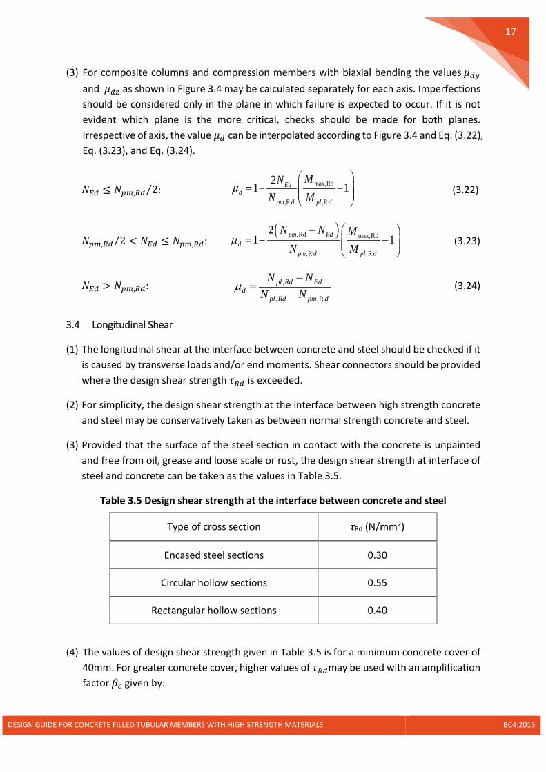
3.4 Longitudinal Shear
(1) The longitudinal shear at the interface between concrete and steel should be checked if it is caused by transverse loads and/or end moments. Shear connectors should be provided where the design shear strength 𝜏𝜏𝑅𝑅𝑦𝑦 is exceeded.
(2) For simplicity, the design shear strength at the interface between high strength concrete and steel may be conservatively taken as between normal strength concrete and steel.
(3) Provided that the surface of the steel section in contact with the concrete is unpainted and free from oil, grease and loose scale or rust, the design shear strength at interface of steel and concrete can be taken as the values in Table 3.5.
Table 3.5 Design shear strength at the interface between concrete and steel
Type of cross section τRd (N/mm2)
Encased steel sections 0.30
Circular hollow sections 0.55
Rectangular hollow sections 0.40
(4) The values of design shear strength given in Table 3.5 is for a minimum concrete cover of 40mm. For greater concrete cover, higher values of 𝜏𝜏𝑅𝑅𝑦𝑦may be used with an amplification factor 𝛽𝛽𝑐𝑐 given by:
DESIGN GUIDE FOR CONCRETE FILLED TUBULAR MEMBERS WITH HIGH STRENGTH MATERIALS BC4:2015

18
40min 1 0.02 1 , 2.5c z
z
cc
β = + −
(3.25)
where
𝑐𝑐𝑧𝑧 is the nominal value of concrete cover in mm
3.5 Load Introduction
(1) Shear studs should be provided in the load introduction area if the design shear strength is exceeded at the interface between concrete and steel tube. In absence of a more accurate method, the introduction length should not exceed 2𝑑𝑑 or 𝐿𝐿 3⁄ as shown in Figure 3.5, where 𝑑𝑑 is the minimum transverse dimension of the concrete filled steel tubular column and 𝐿𝐿 is the system length of the column.
Figure 3.5 Load introduction area
(2) The shear studs may be replaced by welded reinforcements or weld beads as shown in Figure 3.6. The design shear resistance is calculated as:
Rw w w w cNP N A fβ= (3.26)
where
𝛽𝛽𝑤𝑤 = 1.54 − 0.0143𝐷𝐷 𝑡𝑡𝑐𝑐⁄ , for 𝐷𝐷 𝑡𝑡𝑐𝑐⁄ > 55, 𝛽𝛽𝑤𝑤 = 0.7535
𝐷𝐷 is the column diameter
𝑡𝑡𝑐𝑐 is the thickness of column tube
𝑁𝑁𝑤𝑤 is the number of welded reinforcements or weld beads, ≤ 3
Introduction length<2d or L/3
DESIGN GUIDE FOR CONCRETE FILLED TUBULAR MEMBERS WITH HIGH STRENGTH MATERIALS BC4:2015

19
𝐴𝐴𝑤𝑤 is the projected cross-sectional area of welded reinforcement or weld bead
𝑓𝑓𝑐𝑐𝑁𝑁 is the bearing strength of concrete, = 𝑚𝑚𝑚𝑚𝑚𝑚(𝐴𝐴𝑐𝑐 𝐴𝐴𝑤𝑤⁄ , 5)𝑓𝑓𝑐𝑐𝑦𝑦
𝑓𝑓𝑐𝑐𝑦𝑦 is the design strength of concrete
𝐴𝐴𝑐𝑐 is the cross-sectional area of concrete
Figure 3.6 Load introduction to steel tubes by weld beads or welded reinforcements
Weld beadsor Welded reinforcements
DESIGN GUIDE FOR CONCRETE FILLED TUBULAR MEMBERS WITH HIGH STRENGTH MATERIALS BC4:2015

20
4 Connection Detailing
4.1 General
(1) The joints may be classified into nominally pinned, semi-rigid and rigid. The classification should be in accordance with EN 1993-1-8. Joint behaviour should be taken into account in structural analysis based on each type of joint.
(2) The rules for semi-rigid joints are not applicable for steels with grades greater than S460. The joint of steel sections with high strength grade should be either rigid or pinned, and the resistance of the joint should be determined based on elastic distribution of forces over the components of the joint.
(3) The partial safety factors 𝛾𝛾M for joint design should comply with EN 1993-1-8 as given in Table 4.1, regardless of the steel grade.
Table 4.1 Partial safety factors for joint design
Applications 𝜸𝜸𝐌𝐌 Values
Resistance of cross-sections 𝛾𝛾𝑀𝑀0 1.0 Resistance of members to instability assessed by member checks 𝛾𝛾𝑀𝑀1 1.0
Resistance of cross-sections in tension to fracture 𝛾𝛾𝑀𝑀2 1.25 Resistance of bolts Resistance of welds Resistance of plates in bearing
𝛾𝛾𝑀𝑀2 1.25
Slip resistance - at ultimate limit state - at serviceability limit state
𝛾𝛾𝑀𝑀3
𝛾𝛾𝑀𝑀3,𝑠𝑠𝑒𝑒𝑐𝑐
1.25 1.1
Preload of high strength bolts 𝛾𝛾𝑀𝑀7 1.1
4.2 Column Splices
(1) Bolted splices are not recommended unless the leaking of concrete during casting can be effectively prevented.
(2) In case where the bolted splices are used, they should be placed near to the contraflexural point of moment of the column.
(3) Welded splices with either full penetration or partial penetration butt welds are allowed.
(4) For splice joints with full penetration butt welds, it is not necessary to check the joint resistance against the design loads, unless an undermatched electrode is used for the welds. In such cases, the welded joint resistance should be determined by using the strength of the undermatched electrode.
DESIGN GUIDE FOR CONCRETE FILLED TUBULAR MEMBERS WITH HIGH STRENGTH MATERIALS BC4:2015
21
(5) For splices with partial penetration butt welds, the splice joint resistance should be determined on the basis of method for fillet welds with an effective throat thickness equal to the penetration depth.
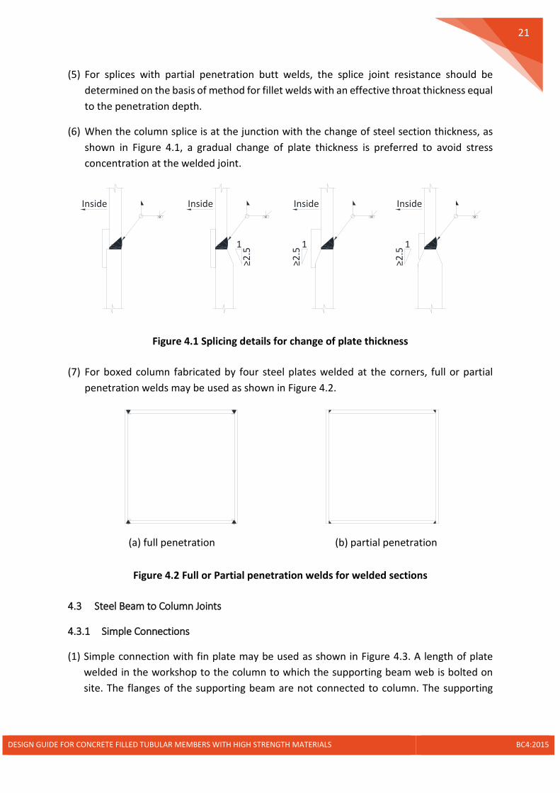
(6) When the column splice is at the junction with the change of steel section thickness, as shown in Figure 4.1, a gradual change of plate thickness is preferred to avoid stress concentration at the welded joint.
Figure 4.1 Splicing details for change of plate thickness
(7) For boxed column fabricated by four steel plates welded at the corners, full or partial penetration welds may be used as shown in Figure 4.2.
(a) full penetration (b) partial penetration
Figure 4.2 Full or Partial penetration welds for welded sections
4.3 Steel Beam to Column Joints
4.3.1 Simple Connections
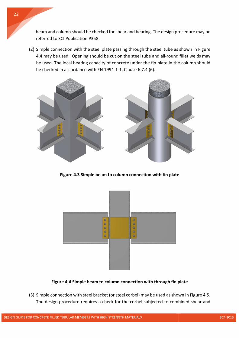
(1) Simple connection with fin plate may be used as shown in Figure 4.3. A length of plate welded in the workshop to the column to which the supporting beam web is bolted on site. The flanges of the supporting beam are not connected to column. The supporting
InsideM
InsideM
1≥2
.51
≥2.5
InsideM
1
≥2.5
InsideM
DESIGN GUIDE FOR CONCRETE FILLED TUBULAR MEMBERS WITH HIGH STRENGTH MATERIALS BC4:2015
22
beam and column should be checked for shear and bearing. The design procedure may be referred to SCI Publication P358.
(2) Simple connection with the steel plate passing through the steel tube as shown in Figure 4.4 may be used. Opening should be cut on the steel tube and all-round fillet welds may be used. The local bearing capacity of concrete under the fin plate in the column should be checked in accordance with EN 1994-1-1, Clause 6.7.4 (6).
Figure 4.3 Simple beam to column connection with fin plate
Figure 4.4 Simple beam to column connection with through fin plate
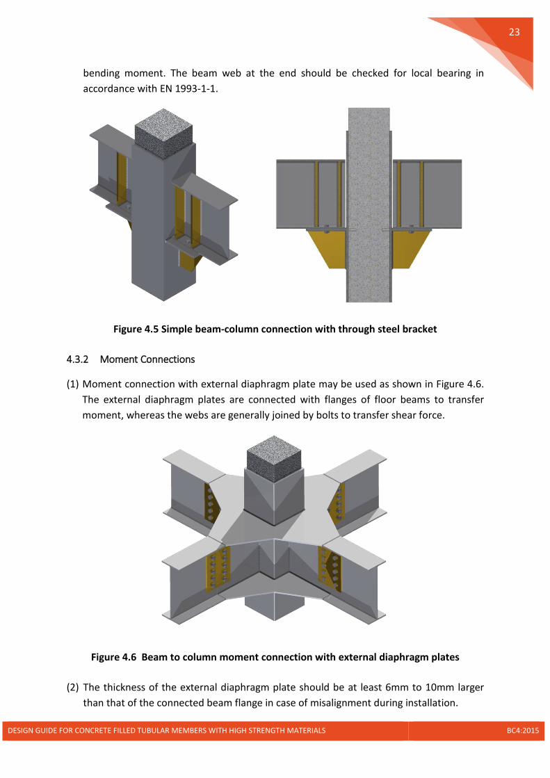
(3) Simple connection with steel bracket (or steel corbel) may be used as shown in Figure 4.5. The design procedure requires a check for the corbel subjected to combined shear and
DESIGN GUIDE FOR CONCRETE FILLED TUBULAR MEMBERS WITH HIGH STRENGTH MATERIALS BC4:2015
23
bending moment. The beam web at the end should be checked for local bearing in accordance with EN 1993-1-1.
Figure 4.5 Simple beam-column connection with through steel bracket
4.3.2 Moment Connections
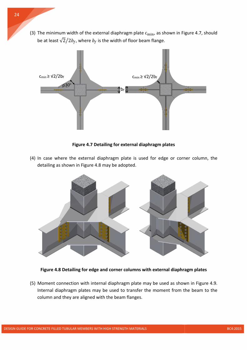
(1) Moment connection with external diaphragm plate may be used as shown in Figure 4.6. The external diaphragm plates are connected with flanges of floor beams to transfer moment, whereas the webs are generally joined by bolts to transfer shear force.
Figure 4.6 Beam to column moment connection with external diaphragm plates
(2) The thickness of the external diaphragm plate should be at least 6mm to 10mm larger than that of the connected beam flange in case of misalignment during installation.
DESIGN GUIDE FOR CONCRETE FILLED TUBULAR MEMBERS WITH HIGH STRENGTH MATERIALS BC4:2015
24
(3) The minimum width of the external diaphragm plate cmin, as shown in Figure 4.7, should be at least √2 2𝑏𝑏𝑒𝑒� , where 𝑏𝑏𝑒𝑒 is the width of floor beam flange.
Figure 4.7 Detailing for external diaphragm plates
(4) In case where the external diaphragm plate is used for edge or corner column, the detailing as shown in Figure 4.8 may be adopted.
Figure 4.8 Detailing for edge and corner columns with external diaphragm plates
(5) Moment connection with internal diaphragm plate may be used as shown in Figure 4.9. Internal diaphragm plates may be used to transfer the moment from the beam to the column and they are aligned with the beam flanges.
≤30o bf
cmin ≥ √2/2bf cmin ≥ √2/2bf
DESIGN GUIDE FOR CONCRETE FILLED TUBULAR MEMBERS WITH HIGH STRENGTH MATERIALS BC4:2015

25
Figure 4.9 Beam to column moment connection with internal diaphragm plates
Figure 4.10 Detailing for internal diaphragm plate
(6) The thickness of internal diaphragm plate should be 3mm to 5mm larger than that of floor beam flanges to avoid misalignment. The width of internal diaphragm plate should be at least equal to 𝑏𝑏f 2⁄ as shown in Figure 4.10.
(7) Opening area should be prepared for concrete casting as show in Figure 4.10. The opening could be either rectangular or circular. The opening size should be at least 100mm and the area of opening should be greater than 15% the cross-sectional area of the core concrete. Four venting holes should be provided with diameter of 30mm but not less than the thickness of the internal diaphragm plate.
Venting hole D ≥ 100mm
Opening for casting
A ≥ 15% Ac
cmin ≥ bf /2
DESIGN GUIDE FOR CONCRETE FILLED TUBULAR MEMBERS WITH HIGH STRENGTH MATERIALS BC4:2015
26
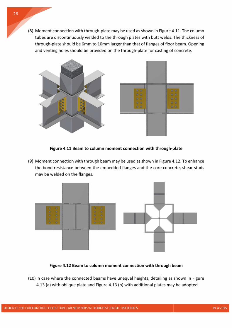
(8) Moment connection with through-plate may be used as shown in Figure 4.11. The column tubes are discontinuously welded to the through plates with butt welds. The thickness of through-plate should be 6mm to 10mm larger than that of flanges of floor beam. Opening and venting holes should be provided on the through-plate for casting of concrete.
Figure 4.11 Beam to column moment connection with through-plate
(9) Moment connection with through beam may be used as shown in Figure 4.12. To enhance the bond resistance between the embedded flanges and the core concrete, shear studs may be welded on the flanges.
Figure 4.12 Beam to column moment connection with through beam
(10) In case where the connected beams have unequal heights, detailing as shown in Figure 4.13 (a) with oblique plate and Figure 4.13 (b) with additional plates may be adopted.
DESIGN GUIDE FOR CONCRETE FILLED TUBULAR MEMBERS WITH HIGH STRENGTH MATERIALS BC4:2015

27
Figure 4.13 Steel beams with unequal depths connected to columns
4.4 Concrete Beam to Column Joints
4.4.1 Simple Connections
(1) Simple connection with the steel corbel may be used as shown in Figure 4.14.
Figure 4.14 Concrete beam to column simple connection with supporting corbel
Figure 4.15 Concrete beam to column simple connection with embedded corbels
(a)
(a) (b)
(b)
DESIGN GUIDE FOR CONCRETE FILLED TUBULAR MEMBERS WITH HIGH STRENGTH MATERIALS BC4:2015
28
(2) In case where the head room is not enough, the steel corbels may be embedded in the concrete beams as shown in Figure 4.15(a). When the reaction forces from beams are large, the corbels may be continuous through the steel tube as shown in Figure 4.15(b).
4.4.2 Moment Connections
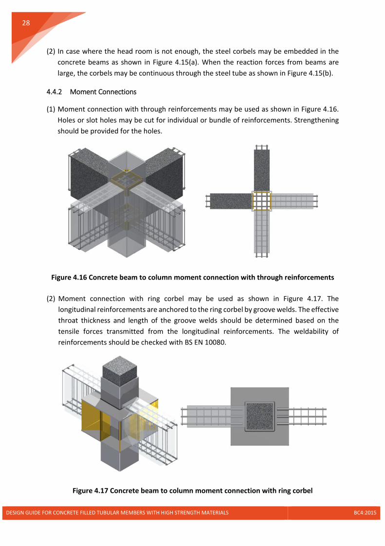
(1) Moment connection with through reinforcements may be used as shown in Figure 4.16. Holes or slot holes may be cut for individual or bundle of reinforcements. Strengthening should be provided for the holes.
Figure 4.16 Concrete beam to column moment connection with through reinforcements
(2) Moment connection with ring corbel may be used as shown in Figure 4.17. The longitudinal reinforcements are anchored to the ring corbel by groove welds. The effective throat thickness and length of the groove welds should be determined based on the tensile forces transmitted from the longitudinal reinforcements. The weldability of reinforcements should be checked with BS EN 10080.
Figure 4.17 Concrete beam to column moment connection with ring corbel
DESIGN GUIDE FOR CONCRETE FILLED TUBULAR MEMBERS WITH HIGH STRENGTH MATERIALS BC4:2015

29
4.5 Column Base
4.5.1 Simple Connections
(1) Column base with holding-down bolts may be used as shown in Figure 4.18 (a). Design for column base with pinned connection could be referred to SCI Publication P358.
Figure 4.18 Column base with holding-down bolts
(2) The bedding grout shall be of non-shrinkage and at least equal in strength to that of foundation concrete. A bedding spacing of 25mm to 50mm is generally adopted, which gives reasonable access for thoroughly filling the space under the base plate.
(3) The bedding grout may be fine concrete with a maximum aggregate of 10mm. The usual mix is 1:1.25:2 with a water-cement ratio of between 0.4 and 0.45.
(4) The use of holding down bolts may be in accordance with BS 7419. The embedded length of the bolt in the concrete should be in the range of 16 to 18 bolt diameters.
(5) The use of washers may be referred to BS EN ISO 7091. Alternatively, the washers may be cut from plates.
(6) In case where the transfer of high shear force to the column base is required, a shear stub (shear key) welded to the underside of the base plate may be necessary as shown in Figure 4.18 (b).
4.5.2 Moment-Resisting Column Base Connections
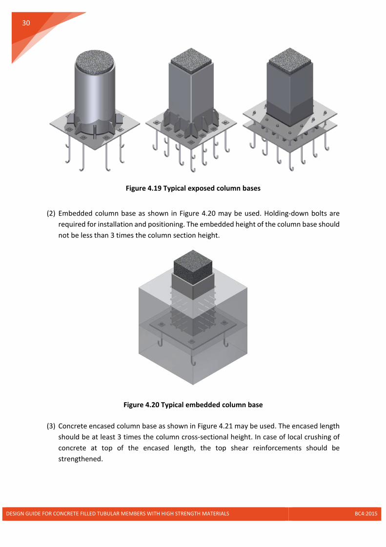
(1) Exposed column bases as shown in Figure 4.19 may be used. When necessary, double base plates may be used to reduce the force acting on the plate stiffeners, and to reduce the number of stiffeners required.
(a) (b)
DESIGN GUIDE FOR CONCRETE FILLED TUBULAR MEMBERS WITH HIGH STRENGTH MATERIALS BC4:2015
30
Figure 4.19 Typical exposed column bases
(2) Embedded column base as shown in Figure 4.20 may be used. Holding-down bolts are required for installation and positioning. The embedded height of the column base should not be less than 3 times the column section height.
Figure 4.20 Typical embedded column base
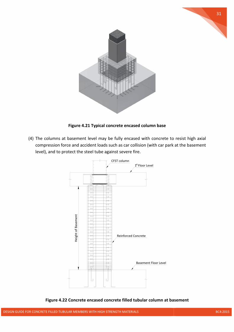
(3) Concrete encased column base as shown in Figure 4.21 may be used. The encased length should be at least 3 times the column cross-sectional height. In case of local crushing of concrete at top of the encased length, the top shear reinforcements should be strengthened.
DESIGN GUIDE FOR CONCRETE FILLED TUBULAR MEMBERS WITH HIGH STRENGTH MATERIALS BC4:2015
31
Figure 4.21 Typical concrete encased column base
(4) The columns at basement level may be fully encased with concrete to resist high axial compression force and accident loads such as car collision (with car park at the basement level), and to protect the steel tube against severe fire.
Figure 4.22 Concrete encased concrete filled tubular column at basement
Heig
ht o
f Bas
emen
t
1 Floor Levelst
Basement Floor Level
Reinforced Concrete
CFST column
DESIGN GUIDE FOR CONCRETE FILLED TUBULAR MEMBERS WITH HIGH STRENGTH MATERIALS BC4:2015

32
5 Special Considerations for High Strength Materials
5.1 Fire Resistance of Concrete Filled Tubular Members
(1) The fire rating should be determined in accordance with the SCDF fire code for various types of occupancy.
(2) To determine the fire resistance of a concrete filled steel tubular member, the tabulated values of minimum cross-sectional dimensions and ratio of reinforcement for the given load level and fire rating, and the simple calculation models may be followed.
(3) The advanced fire engineering approach which practically resorts to finite element analysis are allowed. The advanced calculation models of thermal response shall be based on the acknowledged principles and assumptions of the theory of heat transfer.
(4) For a concrete filled steel tubular member with normal strength concrete and mild steel, a complete thermal-stress analysis may not be necessary provided the temperature of the hollow section is lower than 350oC.
(5) For a concrete filled steel tubular member with high strength concrete (fck > 50N/mm2) or high tensile steel (fy > 460N/mm2), the fire resistance may be assumed to be satisfied provided the temperature of the hollow section is less than 300oC.
(6) The risk of spalling should be taken into account. For concrete grades C55/67 to C80/95, the spalling is unlikely to occur when the moisture content is less than 3.0% and the maximum content of silica fume is less than 6% by weight of cement. Above the limitations, a more accurate assessment of moisture content, silica fume content, type of aggregate, permeability of concrete and heating rate should be taken into account. The assessment could be based on laboratory trial or specialist advices.
(7) For concrete grades higher than C80/95, spalling can occur in any situation for exposure directly to the fire. Thus at least one of the following methods should be provided:
- Include in the concrete mix more than 2 kg/m3 of monofilament propylene fibres;
- A type of concrete for which it has been demonstrated by local experience or by testing that no spalling occurs under fire exposure.
(8) The addition of propylene fibres may affect the workability of concrete. In case where the high strength concrete is pumped into concrete filled steel tubular columns, specialist advice should be consulted for the pumpability.
(9) For the release of vapour from the concrete filled steel tubular columns, the hollow steel section shall contain steaming holes with a diameter of not less than 20mm located at least one at the top and one at the bottom of the column in every storey. The spacing of these holes should not exceed 5m along the column length.
DESIGN GUIDE FOR CONCRETE FILLED TUBULAR MEMBERS WITH HIGH STRENGTH MATERIALS BC4:2015

33
5.2 Fabrication of High Tensile Steel Sections
(1) For high tensile steel in the quenched and tempered condition produced in according with EN 10025-6 and high tensile steel in the thermo-mechanically controlled condition in accordance with EN 10149-2, the hot forming is only permitted up to the stress relief annealing temperature. Provided higher temperatures are used for the hot forming, an additional quenching and tempering operation shall be required in which case the manufacturer shall be consulted.
(2) For high tensile steel in the quenched and tempered condition in accordance with EN 10025-6 (2004), the minimum inside bend radii for cold forming without cracks induced should be conformed to the values in Table 5.1.
Table 5.1 Minimum bend radii for cold forming of quenched and tempered steels
Steel class Minimum inside bend radii (𝐦𝐦𝐦𝐦)
Axis of bend in transverse direction
Axis of bend in longitudinal direction
S500Q/QL/QL1 3t 4t
S550Q/QL/QL1 3t 4t
Note: The values are applicable for bend angles ≤ 90o and plate thickness 𝐭𝐭 ≤ 𝟏𝟏𝟏𝟏𝐦𝐦𝐦𝐦.
Table 5.2 Minimum bend radii for cold forming of thermo-mechanically controlled steels
Steel class Minimum inside bend radii for nominal thickness in mm
𝑡𝑡 ≤ 3 3 < 𝑡𝑡 ≤ 6 𝑡𝑡 > 6
S500MC 1.0t 1.5t 2.0t
S550MC 1.0t 1.5t 2.0t
Note: The values are applicable for bend angles ≤ 90o.
(3) For high tensile steel in the thermo-mechanically controlled condition in accordance with EN 10149-2 (1996), the minimum inside bend radii for cold forming is given in Table 5.2.
(4) High tensile steel plates can be cold sheared. The maximum thickness of shearing should be determined based on the power available in the shear machine and the material used in the shear blades. The quality of the sheared edge are influenced by the machine setup and therefore the cutting blades should be well maintained.
DESIGN GUIDE FOR CONCRETE FILLED TUBULAR MEMBERS WITH HIGH STRENGTH MATERIALS BC4:2015
34
(5) High tensile steel plates may be cut by oxy-fuel gas flame, abrasive water jet, and plasma techniques. Care should be taken as cutting underwater could result in a high hardness edge owing to the quenching effect.
(6) Hardness of free cut edges should be checked after cutting. For high tensile steels as concerned by EN 10025-6 and EN 10149-2, the permitted maximum hardness (HV 10) at the free cut edge is 450. Hardness testing with a load of HV10 shall be performed in accordance with EN 1043-1 or EN ISO 6507-1.
(7) The execution of bolt holes for high tensile steels may be done by process such as drilling, punching, laser, plasma or other thermal cutting. The local hardness and quality of cut edges around a finished hole should fulfill the requirements as for cutting.
(8) Hydrogen induced cold cracking for welding high tensile steel should be avoided. Appropriate welding procedures may be determined in accordance with Method A and Method B in EN 1011-2, JIS B 8285 and AWS D1.1.
(9) The necessity and requirements for preheat during welding should be consulted with steel manufacturers. In case where it is absent, Method B of EN 1011-2 may be referred to.
(10) Preheat should be extended to a zone of width of at least 4 times the thickness of the plate per side on both sides of the weld seam. For thickness greater than 25 mm, 100 mm adjacent to the seam on both sides is adequate.
(11) In cases where adequate preheat is impracticable, it is advisable to use austenitic or Ni-based welding consumables.
(12) Post-heat may be necessary when there is an increased risk of cold cracking, such as submerged arc weld for high tensile steels and a thickness greater than 30mm. The post-heat can be implemented by means of soaking, such as 2h/250oC, immediately after the welding.
(13) Hydrogen embrittlement induced by hot-dip galvanizing the high tensile steel plates should be avoided. To remove the potential for hydrogen embrittlement, heating to 150°C after pickling and before galvanizing may be adopted for expulsion of hydrogen from the grain boundaries of steel. Another way is to use mechanical cleaning, such as shot or sand blasting, to remove the impurities instead of pickling. Nevertheless, a flash pickling after abrasive blast cleaning is required to remove any final traces of blast media before hot-dip galvanization.
(14) Test for the likelihood of hydrogen embrittlement for galvanized high tensile steels may be referred to ASTM A 143/A 143M.
(15) The inspection and testing procedures for welds on high tensile steels are similar as for mild steels, except special attention should be paid on the hydrogen induced cracks.
DESIGN GUIDE FOR CONCRETE FILLED TUBULAR MEMBERS WITH HIGH STRENGTH MATERIALS BC4:2015

35
Visual examination and non-destructive testing methods, such as radiographic or ultrasonic inspection, may be adopted.
(16) Due to the risk of delayed cracking of high tensile steel welds, a period of at least 48 hours is required before the inspection. The period shall be stated in the inspection records. For welds with heat-treatment to reduce the hydrogen content, the inspection may be carried out immediately after the heat-treatment.
(17) Personnel performing the visual examination and non-destructive testing shall have documented training and qualifications in accordance with EN ISO 9712.
(18) For direct visual examination, the access shall be sufficient to place the eye within 600 mm of the examined weld at an angle not less than 30° relative to background plane. An additional light source may be necessary to increase the contrast and relief between imperfections and the background. The visual examination shall be done in accordance with EN ISO 17637.
(19) In case where the radiographic inspection is chosen, Class B techniques, being more sensitive to cracks compared with Class A, should be used for high tensile steel welds. The technical requirements for Class B inspection should comply with EN ISO 17636.
(20) Provided the ultrasonic inspection is adopted, special attention should be paid for high tensile steel plates made from thermo-mechanically controlled process. General requirements for ultrasonic inspection shall conform to EN ISO 17640.
5.3 Preparation of High Strength Concrete
(1) High strength concrete may be produced with conventional Portland cement combined with fly ash and ground granulated blast furnace, silica fume slag. High early strength cements should be avoided. To maintain good workability, the cement composition and finenesses and its compatibility with the chemical admixtures should be carefully studied. Experience has shown that low-C3A cements generally produce concrete with improved rheology.
(2) Care should be taken for the selection of aggregate to avoid the weak links formed on the aggregates. The higher the strength, the smaller the maximum size of coarse aggregate should be used. Up to 70N/mm2, compressive strength may be achieved with a good coarse aggregate of a maximum size ranging from 20 to 28 mm. Crushed rock aggregates should preferably be used.
(3) Particle size distribution of fine aggregate should meet the Eurocode specifications. Fine sands should not be used, particularly those with high absorption.
(4) Using supplementary cementitious materials, such as blast furnace slag, fly ash and natural pozzolans, not only reduces the production cost of concrete, but also addresses
DESIGN GUIDE FOR CONCRETE FILLED TUBULAR MEMBERS WITH HIGH STRENGTH MATERIALS BC4:2015

36
the slump loss problem. Generally, silica fume is necessary to produce the high strength concrete.
(5) Superplasticizer should be used to achieve maximum water reduction. The compatibility between cement and chemical admixtures and the optimum dosage of an admixture or combination of admixtures should be determined by laboratory experiments.
(6) Basic proportioning of high strength concrete mixture should follow the same method as for normal strength concrete, with the objective of producing a cohesive mix with minimum voids. Theoretical calculations or subjective laboratory trials may be necessary.
(7) The basic strength to water/cement ratio relationships used for producing normal strength concrete are equally valid when applied to high strength concrete, except that the target water/cement ratio can be in the range of 0.18-0.3 or even lower.
(8) High strength concrete containing superplasticizer should be transported, placed and finished prior to the loss of workability.
(9) The same production and quality control techniques for normal strength concrete should be applied to high strength concrete. The importance of strict control over material quality as well as over the production and execution processes should not be over-emphasized for high strength concrete.
(10) More compaction is normally required for high strength concrete than for normal strength concrete of similar slump. As the loss in workability is more rapid, prompt finishing becomes essential. To avoid plastic shrinkage, the finished concrete surface needs to be covered rapidly with water-retaining curing agents.
5.4 Casting of Concrete in Steel Tubes
(1) Concrete casting in hollow steel tubes may be conducted by means of tremie tube and pumping.
(2) The tremie should be fabricated of heavy-gage steel pipe to withstand all anticipated handling stresses, and should have a diameter large enough to prevent aggregate-induced blockages. Pipes with diameter of 200 to 300 mm are generally recommended. A stable platform should be provided to support the tremie during the placement of concrete. Tremie pipes should be embedded in the fresh concrete with a depth of 1.0 ~ 1.5 m. The embedment depths depend on placement rates and setting time of the concrete. All vertical movements of the tremie pipes should be done slowly and carefully to prevent loss of seal.
(3) The maximum height of pumping should not exceed 60m. For composite columns with internal diaphragm plates, the pumping rate should not exceed 1m/min to avoid the air entrapment. The location of pumping inlet should be 300mm away from the floor level.
DESIGN GUIDE FOR CONCRETE FILLED TUBULAR MEMBERS WITH HIGH STRENGTH MATERIALS BC4:2015

37
5.5 Differential Column Shortening
(1) Differential shortening between columns and core walls due to different material strengths, stress levels, and long-term creep and shrinkage of concrete should be taken into account.
(2) Aggregates play an important role in both creep and shrinkage. Increase of fraction, size and modulus of aggregates may cause decreases of creep and shrinkage. In this aspect, high strength concrete exhibits less creep and shrinkage than normal strength concrete. In situation of large differential column shortening, high strength concrete is recommended.
(3) More accurate analysis may be used to determine the differential shortening between columns and core walls, taking into account for the time dependent creep and shrinkage strains in accordance with EN 1992-1-1. The effect of construction sequence should be taken into account.
(4) Column size, concrete strength and steel contribution ratio etc. may be adjusted to reduce the differential shortening. Alternatively, column length may be corrected based on the calculated differential shortening. The correction may be done after several storeys have been constructed.
(5) Simple connections allowing for vertical slip may be used for the floor beams and outriggers to relief the internal forces induced by the differential shortening. In case where rigid connections are adopted, the connections may be made simple in the construction stage and become rigid after the creep and shrinkage have sufficiently developed.
DESIGN GUIDE FOR CONCRETE FILLED TUBULAR MEMBERS WITH HIGH STRENGTH MATERIALS BC4:2015

38
References
ASTM A 143/A 143M (2003). Standard practice for safe guarding against embrittlement of hot-dip galvanization structural steel products and procedure for detecting embrittlement.
AWS D1.1/D1.1M (2010). Structural welding code – Steel.
BC 1 (2012). Design guide on use of alternative structural steel to BS 5950 and Eurocode 3. Building and Construction Authority, Singapore.
BC 2 (2008). Design guide of high strength concrete to Singapore standard CP 65. BCA Sustainable Construction Series – 3, BCA Academy, Singapore.
BS 4449 (1997). Specification for carbon steel bars for the reinforcement of concrete.
BS 4449 (2005) + A2 (2009). Steel for the reinforcement of concrete – Weldable reinforcing steel – Bar, coil and decoilded product – Specification.
BS 5950-1 (2000). Structural use of steelwork in building. Part 1: Code of practice for design - Rolled and welded sections.
BS 7419 (2012). Specification for holding down bolts.
BS EN 10080 (2005). Steel for the reinforcement of concrete – Weldable reinforcing steel – General.
BS EN ISO 898-1 (1999). Mechanical properties of fasteners made of carbon steel and alloy steel – Part 1: Bolts, screws and studs.
BS EN ISO 7091 (2000). Plain washers, Normal series, Product Grade C.
BS EN ISO 13918 (2008). Welding – Studs and ceramic ferrules for arc stud welding.
BS EN ISO 14555 (2006). Welding – Arc stud welding of metallic materials.
EN 1011-2 (2001). Welding – Recommendations for welding of metallic materials – Part 2: Arc welding of ferritic steels.
EN 1992-1-1 (2004). Eurocode 2: Design of concrete structures – Part 1-1: General rules and rules for buildings.
EN 1993-1-8 (2005). Eurocode 3 - Design of steel structures – Part 1-8: Design of joints.
EN 1993-1-10 (2005). Eurocode 3 - Design of steel structures – Part 1-10: Materials toughness and through-thickness properties.
EN 1993-1-12 (2007). Eurocode 3 – Design of steel structures – Part 1-12: Additional rules for the extension of EN 1993 up to steel grades S700.
EN 1994-1-1 (2004). Eurocode 4: Design of composite steel and concrete structures – Part 1-1: General rules and rules for buildings.
EN 1994-1-2 (2005). Eurocode 4: Design of composite steel and concrete structures – Part 1-2: General rules – Structural fire design.
EN 10025-6 (2004). Hot-rolled products of structural steels – Part 6: Technical delivery conditions for flat products of high strength structural steels in the quenched and tempered condition.
DESIGN GUIDE FOR CONCRETE FILLED TUBULAR MEMBERS WITH HIGH STRENGTH MATERIALS BC4:2015

39
EN 10149-2 (1996). Hot-rolled flat products made of high strength steels for cold forming – Part 2: Delivery conditions for thermomechanically rolled steels.
EN ISO 1043-1 (2011). Plastics - Symbols and abbreviated terms. Part 1: Basic polymers and their special characteristics.
EN ISO 6507-1 (2005). Metallic materials - Vickers hardness test. Part 1: Test method.
EN ISO 9712 (2012). Non-destructive testing of welds – Qualification and certification of NDT personnel.
EN ISO 17636-1 (2013). Non-destructive testing of welds – Radiographic testing. X- and gamma-ray techniques with film.
EN ISO 17636-2 (2013). Non-destructive testing of welds – Radiographic testing. X- and gamma-ray techniques with digital detectors.
EN ISO 17637 (2011). Non-destructive testing welds – Visual testing of fusion-welded joints.
EN ISO 17640 (2010). Non-destructive testing welds – Ultrasonic testing. Techniques, testing levels, and assessment.
JIS B 8285 (2010). Welding procedure qualification test for pressure vessels.
Liew J.Y.R., Xiong M.X. (2015). Design guide for concrete filled tubular members with high strength materials – An extension of Eurocode 4 method to C90/105 concrete and S550 steel.
Steel Construction Institute (SCI: P358), (2011). Joints in steel construction: Simple joints to Eurocode 3, Steel Construction Institute, Tata Steel and British Construction Steel Work Association, UK .
DESIGN GUIDE FOR CONCRETE FILLED TUBULAR MEMBERS WITH HIGH STRENGTH MATERIALS BC4:2015
40
Appendix A Design Flowchart
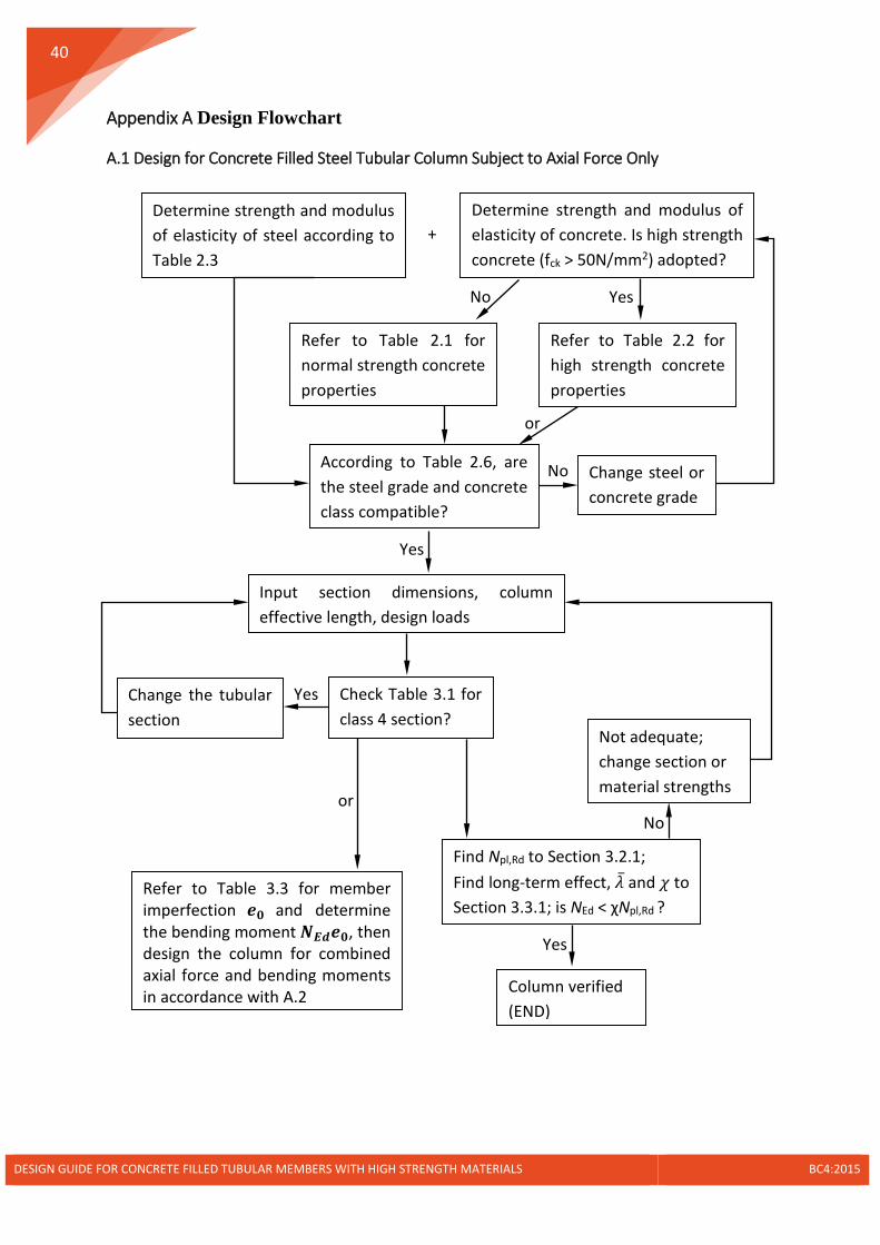
A.1 Design for Concrete Filled Steel Tubular Column Subject to Axial Force Only
c
Determine strength and modulus of elasticity of concrete. Is high strength concrete (fck > 50N/mm2) adopted?
Refer to Table 2.1 for normal strength concrete properties
No
Input section dimensions, column effective length, design loads
Check Table 3.1 for class 4 section?
Change the tubular section
Yes
Find Npl,Rd to Section 3.2.1; Find long-term effect, �̅�𝜆 and 𝜒𝜒 to Section 3.3.1; is NEd < χNpl,Rd ?
No
Not adequate; change section or material strengths
Refer to Table 2.2 for high strength concrete properties
Yes
Column verified (END)
Yes
According to Table 2.6, are the steel grade and concrete class compatible?
+ Determine strength and modulus of elasticity of steel according to Table 2.3
or
Change steel or concrete grade
No
Yes
Refer to Table 3.3 for member imperfection 𝒆𝒆𝟎𝟎 and determine the bending moment 𝑵𝑵𝑬𝑬𝑬𝑬𝒆𝒆𝟎𝟎, then design the column for combined axial force and bending moments in accordance with A.2
or
DESIGN GUIDE FOR CONCRETE FILLED TUBULAR MEMBERS WITH HIGH STRENGTH MATERIALS BC4:2015

41
A.2 Design for Concrete Filled Steel Tubular Column Subject to Combined Axial Force and Bending Moments
c
Refer to Section 3.2.3 for the simplified interaction curves of the cross-section for both y and z planes, respectively
Determine strength and modulus of elasticity of concrete. Is high strength concrete (fck > 50N/mm2) adopted?
Refer to Table 2.1 for normal strength concrete properties
No
Input section dimensions, column effective length, design loads
Check Table 3.1 for class 4 section?
Change the tubular section
Yes
Refer to Table 2.2 for high strength concrete properties
Yes
According to Table 2.6, are the steel grade and concrete class compatible?
+ Determine strength and modulus of elasticity of steel according to Table 2.3
or
Change steel or concrete grade
No
Yes
Find𝑉𝑉𝑎𝑎,𝐸𝐸𝑦𝑦,𝑉𝑉𝑒𝑒,𝐸𝐸𝑦𝑦, 𝑉𝑉𝑝𝑝𝑝𝑝,𝑎𝑎,𝑅𝑅𝑦𝑦 and 𝑉𝑉𝑝𝑝𝑝𝑝,𝑒𝑒,𝑅𝑅𝑦𝑦 to Section 3.2.2. Is 𝑉𝑉𝑎𝑎,𝐸𝐸𝑦𝑦 > 0.5𝑉𝑉𝑝𝑝𝑝𝑝,𝑎𝑎,𝑅𝑅𝑦𝑦 or 𝑉𝑉𝑒𝑒,𝐸𝐸𝑦𝑦 >𝑉𝑉𝑝𝑝𝑝𝑝,𝑒𝑒,𝑅𝑅𝑦𝑦?
No
No
Find ∅ from Eq.(3-8) and Eq.(3.9), and determine the reduced fyd and fed, alternatively determine the reduced steel section
Yes
To b
e co
ntin
ued
DESIGN GUIDE FOR CONCRETE FILLED TUBULAR MEMBERS WITH HIGH STRENGTH MATERIALS BC4:2015

42
Calculate: Ncr,eff from Section 3.3.2; β for end moments MEd,top, MEd,bot from Table 3.4 and then k1 from Eq.(3.16); k0 for β=1 for imperfection; Second-order design moment:
𝑀𝑀𝐸𝐸𝑦𝑦 = 𝑘𝑘0𝑁𝑁𝐸𝐸𝑦𝑦𝑒𝑒0 + 𝑘𝑘1𝑀𝑀𝐸𝐸𝑦𝑦,1 ≥ 𝑚𝑚𝑎𝑎𝑚𝑚�𝑀𝑀𝐸𝐸𝑦𝑦,𝑡𝑡𝑡𝑡𝑝𝑝,𝑀𝑀𝐸𝐸𝑦𝑦,𝑏𝑏𝑡𝑡𝑡𝑡� (Note: for biaxial bending, the steps can be repeated for the other axis)
From NEd and the interaction diagrams, determine μdy and μdz from Eq.(3.22) to Eq.(3.24). Check the cross-section resistance in accordance with Section 3.3.3.
(END)
Cont
inue
d
DESIGN GUIDE FOR CONCRETE FILLED TUBULAR MEMBERS WITH HIGH STRENGTH MATERIALS BC4:2015