an effective pre-processing technique for robust esprit
TRANSCRIPT

ELEKTRONIKA IR ELEKTROTECHNIKA, ISSN 1392-1215, VOL. 21, NO. 6, 2015
1Abstract—This letter proposes an effective pre-processingtechnique for robust estimation of signal parameters viarotational invariance techniques (ESPRIT)-based single-tonefrequency estimation against an I/Q mismatch. For theimplementation of a high-accuracy ranging/radar system,parametric-based algorithms such as MUSIC, ESPRIT andtheir variations have been adopted due to their superiorestimation capability for single-tone frequency estimations.Since most ranging/radar system have the direct conversionarchitecture, I/Q imbalance problem occurs in the form ofspurious frequencies of the frequency spectrum. For thisreason, the proposed pre-processing technique is designed tomake use of the Hilbert transform structure for receivedsignals. The estimation performance of the proposed pre-processing technique in single-tone frequency is derived andcompared with the results from a Monte-Carlo simulation. Theroot-mean-square error (RMSE) of the proposed method iscompared with that of an ESPRIT-based method for variousparameters.
Index Terms—ESPRIT, pre-processing technique, single-tone frequency, Hilbert transform, I/Q mismatch.
I. INTRODUCTION
Single-tone frequency estimation is one of the mainchallenging in wireless systems [1], [2]. It has numerousapplications in the instrumentation and measurement issuessuch as testing of sine waves and the single-target detectionof the radar. Specifically, millimeter-wave wireless systems(30 GHz to 300 GHz) have recently become increasinglywidespread for radar systems [3] such as frequencymodulated continuous wave (FMCW) radar. In themillimeter-wave systems of the FMCW radar, directconversion types of architecture are commonly implementedto reduce the cost and power consumption of the receiver.However, because the conventional direct conversionarchitecture is sensitive to local oscillation and the matchingbetween the components of the in-phase (I) and quadrature(Q) channels, they have especially an effect to DC offset andI/Q imbalance [4]. Although there have been many efforts toimprove the accuracy of the single-tone parameter estimation
Manuscript received April 14, 2015; accepted September 15, 2015This work was supported by the DGIST R&D Program of the Ministry
of Education & Science Technology, Korea (15-RS-01).
process in the presence of AWGN, this problem has notbeen addressed in conjunction with the I/Q mismatchproblem. The I/Q imbalance problem strongly affects thesignal processing part when estimating parameters.
For frequency estimations, there are parametric and thenon-parametric approaches. Well-known parametricmethods are multiple signal classification (MUSIC) [5],matrix pencil [6], Propagator [7] and estimation of signalparameters via rotational invariance techniques (ESPRIT)[8]. The non-parametric methods include the discrete Fouriertransform (DFT), the Blackman-Turkey method and theBartlett method. The performances of the parametricmethods are superior to those of the non-parametricmethods. Among the parametric methods, ESPRIT achievesquite good performance and is thus widely used. In thisletter, we propose an effective preprocessing technique forrobust ESPRIT-based single-tone frequency estimationagainst instances of I/Q mismatch.
II. SIGNAL MODEL
The chirp signal is used widely for millimeter-wavesystems such as radar [3] and communication systems [9]because a received chirp signal can be changed to asinusoidal signal by a de-chirping process.
A. Received Signal without I/Q ImbalanceIn FMCW radar, the transmitted baseband chirp used for
time delay estimation is obtained from the models as
2symcos ( ) for 0 ,
( ) 20 elsewhere,
c s t t t Ts t
(1)
where ωc denotes the carrier frequency, ωs is the initialfrequency, μ is the rate of change of the instantaneousfrequency of a chirp symbol and Tsym is the signal period of achirp symbol. Assuming a time-invariant channel over Tsym,the received signals, perturbed by additive white Gaussiannoise (AWGN), can be represented by
( ) ( ),y t as t z t (2)
An Effective Pre-processing Technique forRobust ESPRIT-Based Single-Tone Frequency
Estimation against an I/Q MismatchSangdong Kim1, Bong-seok Kim1, Daegun Oh1, Jonghun Lee1
1Advanced Radar Technology (ART) lab., Robotics System Research Division,Daegu Gyeongbuk Institute of Science & Technology,
50-1 Sang-Ri, Hyeonpung-Myeon, Dalseong-Gun, Daegu, 711-873, South [email protected]
http://dx.doi.org/10.5755/j01.eee.21.6.13757
34

ELEKTRONIKA IR ELEKTROTECHNIKA, ISSN 1392-1215, VOL. 21, NO. 6, 2015
where z(t) is the AWGN with noise power σ2 and a and τ arethe complex amplitude and time delay of the received signal,respectively.
To apply parametric-based algorithms such as ESPRITand MUSIC, de-chirping is done to transform the receivedchirp signals into sinusoidal signals. In practice, de-chirpingis defined as the conjugate multiplication of the receivedchirp signals and the reference chirp signals r(t) as in ([9],(9)), such that
*( ) ( ) ( ),d t y t r t (3)
where (·)* means the phase conjugation, d(t) indicates thaty(t) is transformed into exponential form. Eq. (3) shows thatthe transformed signals d(t) as in ([9], eq. (10)) after low-pass filtering have a sinusoidal waveform such that
( )( ) ,j td t ae (4)
where η(t) = -μτt -ωsτ + μ/2τ2. At this point, the time delay ofarrival (TOA) parameter τ is changed to the frequencycomponents of the single-tone sinusoids, as shown in (4).Thus, the time delay parameter estimation problem of thereceived signal y(t) is converted to a frequency estimationproblem of the transformed sinusoids d(t).
B. Received Signal with I/Q ImbalanceSince millimetre-wave radar systems including direct
conversion use extremely high frequencies, they areassociated with the I/Q imbalance. In (3), we assume that thereference chirp signal r(t) has a perfect I/Q balance. For ananalysis of transformed signals perturbed by I/Q imbalance,we assume that the reference chirp signal r'(t) has the I/Qimbalance. The output of the reference r'(t) with the I/Qimbalance is expressed as
( ) cos( ) (1 )sin( ),r t X j X (5)
where X = (ωc + ωs)t + (μt2)/2 and θ and β represent theerror of the phase and the amplitude due to the I/Qimbalance, respectively. The conjugation of (5) can bechanged as [10]
*( ) + ,jX jXr t e e (6)
where 1 2{1 (1 ) }je and
1 2{1 (1 ) }.je After de-chirping and low-passfiltering, it is determined that the transformed signals dIQ(t)due to the I/Q imbalance have a sinusoidal waveform suchthat
( ) ( )IQ ( ) { } ( ).j t j td t a e e z t (7)
The received signal perturbed by I/Q imbalance dIQ(t) canbe represented by a sum of the complex scaled desired signaland interfering signal in the imaginary frequency of thedesired signal.
III. PROPOSED PREPROCESSING TECHNIQUE
The proposed method is composed of a two-step approachfor the compensation of the I/Q imbalance error in order toestimate the single-tone frequency.
j
IQRe d
IQIm d
(I)hilbf
(Q)hilbf
IQd
errf(I)*hilbf
compf
Re
Im
compd
Fig. 1. I/Q imbalance compensator.
A. Preprocessing Technique for I/Q ImbalanceCompensation
The proposed preprocessing technique for the I/Qimbalance compensation is shown in Fig. 1. The discretetime model of dIQ(t) received through analog-to-digitalconverter (ADC) can be described such that
( ) ( )IQ[ ]
( ),
s sj nT j nT
s
d n ae ae
z nT
(8)
where 0,..., 1,n N Ts denotes the sample period and Nrepresents the number of samples per Tsym. In addition, inorder to clarify the signal model with the I/Q imbalance, thefollowing explanation omits the noise term, z[nTs], in (8) forsimplicity. Re(dIQ[n]) and Im(dIQ[n]) in (8) are fed intoHilbert transform functions of the I and Q channels,respectively. Here, Re(·) and Im(·) means the real part of thecomplex signal and the imaginary part of the complex signal,respectively. The goal of the Hilbert transform is to generatea complex-valued N-point signal from the real-valued signalas shown in [11]. In the Hilbert transform of the I channel,Re(dIQ[n]) is transformed by using N-point DFT such that
21(I)
IQIQ0
[ ] Re [ ] ,knN j
Nn
D k d n e
(9)
where 0,1,..., 1k N . After DFT, an N-point one-sidedspectrum is obtained via
(I)IQ
(I)IQ(I) 2
hilb (I)IQ 2
2
[ ], for 0,
2 [ ], for 1 1,[ ]
[ ], for ,
0, for 1 1.
N
N
N
D k k
D k kF k
D k k
k N
(10)
To compute the inverse DFT (IDFT) of the N-point one-sided spectrum (I)
hilb[ ]F k the complex analytic signal iscomputed by
21(I) (I)hilb hilb
01[ ] [ ] ,
knN jN
kf n F k eN
(11)
35

ELEKTRONIKA IR ELEKTROTECHNIKA, ISSN 1392-1215, VOL. 21, NO. 6, 2015
where for 0,1,..., 1n N . The Hilbert transform of the Qchannel from the imaginary-valued signal uses a procedureidentical to that of the Hilbert transform of the I channel.And then, by multiplying (I) *
hilb [ ]f k and (Q)hilb [ ]f k obtained
from the Hilbert transform of the I and Q channels,
respectively, the k-th error term ferr[k]=ˆˆ(1 ) je induced
due to the I/Q imbalance is achieved. After ferr*[k] is
multiplied by (Q)hilb [ ]f k , the k-th compensated signal fcomp[k]
is obtained. Finally, the k-th compensated complex signaldcomp[k] is acquired from the sum of Re(dIQ[k]) and jfcomp[k]i.e. dcomp[k] = Re(dIQ[k]) + jfcomp[k].
B. TOA Estimation by ESPRITUsing the compensated signal dcomp[k] with N samples, the
autocorrelation matrix Rdd of L by L is defined as
dd comp comp0 ,HN LnR d d (12)
where the sequence dcomp = [dcomp[n],…, dcomp[n+L-1]]T withlength L, (·)H and (·)T is the Hermitian transpose andtranspose, respectively. The eigenvalue decomposition(EVD) of Rdd has a form given by
0
*1
dd *
1
0 00
,0
0 0 L
SR S G
G
(13)
where the signal eigenvector matrix S=[s0, …, sM-1] containsM eigenvectors which span the signal subspace of thecorrelation matrix, the noise eigenvector matrix G = [g0, …,gL-M-1] indicates L-M eigenvectors spanning the noisesubspace of the correlation matrix, and λn denotes the n-theigenvalues of Rdd. The largest M eigenvalues of λ0, …, λM-1
correspond to the M eigenvectors of S. The othereigenvalues λM, …, λL-1 correspond to the eigenvectors of Gsuch that λM = …= λL-1=σ2. Let us define the S1 and S2
matrices, which is S1=[IL-1 01×L-1]S, S2=[01×L-1 IL-1]S, IM
denotes M × M identity matrix and 0M×N means M × N zeromatrix. The sub-matrices, as shown in earlier work [12], arefactorized by:
1 11
2 1 1 1
,
,
S = A C
S A DC S C DC S(14)
where A1=[IL-1 01×L-1]A, A2=[01×L-1 IL-1]A, A = [a(ω0) …a(ωM-1)], a(ωm)=[1 e-jωm …e-j(L-1)ωm]T, ωm= mTs, D = diag[δ0… δM-1], diag(·) means the diagonalization of the matrix, δm
denotes the frequency of the transformed complexexponential signal for the m-th time delay of the receivedsignal i.e. δm=e-jωm and C denotes the non-singulartransformation matrix of M by M. In order to obtain δm, theeigenvalues of ϕ is used such as ϕ=C-1DC. Thus, ϕ isexpressed such that
1 1 1 2. * -1 *(S S ) S S (15)
Among several ϕs, the first time delay of received signal0̂ is determined by the first eigenvalue of ϕ such that
0 01ˆ ( ),
sT
(16)
where ( ) means the phase angles for a complex signal.
IV. PERFORMANCE ANALYSIS OF RMSE AND CRLBIn this section, the reduced root-mean-square error
(RMSE) of the estimator for the received signal distorted bythe I/Q imbalance, the ratio of the RMSE of the proposedmethod to the RMSE of the signal perturbed by the I/Qimbalance and the Cramer-Rao lower bound (CRLB) arederived. The distorted signal, dIQ[n], leads to a signal tonoise ratio (SNR) reduction of the received signal. From (7),the distorted signal dIQ[n] is divided into the negativefrequency and the positive frequency. Compared to (4), theamplitude of the negative frequency decreases with .
Therefore, the reduced SNR ∆ due to can be expressedas follows
1020log ( ). (17)
In the AWGN channel, the RMSE of the estimated TOAfor the signal perturbed due to the I/Q imbalance δIQ can beexpressed as in (17) from earlier work [6] with the SNRwhich denotes as γ i.e. γ=a2/σ2 such as
IQ 0.1 ( )1 1 .
10sNT
(18)
The RMSE of the proposed method has similarperformance comparing with the ideal ESPRIT because theproposed method removes the effect of the I/Q imbalance.The ratio of the RMSE of the proposed method to the RMSEof the signal perturbed due to an I/Q imbalance R can beformulated such that
0.10.1 0.1( )1 1 10 .
10 10R
(19)
Therefore, the RMSE of the proposed method is improvedwith .
In the CRLB, the ESPRIT-based TOA estimation is basedon a single-tone sinusoid signal. For the received signal in(4) in the AWGN channel, the CRLB for the ESPRIT-basedTOA estimation δτ is derived from an earlier result [10] suchthat
22 2 26 .
2 ( 1) sN N T
(20)
V. SIMULATION RESULTS
We present Monte-Carlo simulation results averaged over10,000 estimates to verify the performance of the proposed
36

ELEKTRONIKA IR ELEKTROTECHNIKA, ISSN 1392-1215, VOL. 21, NO. 6, 2015
algorithm. The TOA performance of the proposed algorithmis compared with those by conventional algorithms, in thiscase the ESPRIT-based TOA estimation algorithm, in avariety of the I/Q imbalance cases. This letter only takes intoaccount the RMSE for single-tone frequency. For theproposed and conventional algorithms, their RMSEs are
defined such that 21, 11
1/ ,N
nn
N
where 1,n is the
first time delay estimation of the n-th Monte-Carlo trial andN is 10,000. In the following simulations, we set theparameters as shown in Table I.
TABLE I. SIMULATION PARAMETERS FOR AWGN CHANNEL.Parameter Value
μ 7.3158 × 10¹²
Ts 31.25 nsTsym 1.1875 μs
In Fig. 2, the proposed algorithm is analysed for theRMSE of the estimated TOA for the signal perturbed due tothe I/Q imbalance and compared to other algorithms andCRLB values. We compare the RMSE of the ideal ESPRITalgorithm with RMSE of the proposed estimator in TOA.Because the analysis assumes a high SNR, the analysedRMSE and the simulation results for the proposedalgorithms are not well matched in SNR areas below 5 dB inFig. 2.
0 2 4 6 8 10 12 14 16 18 20
10-9
10-8
10-7
SNR(dB)
RM
SE
ESPRIT w/o I/Q imbalanceCRLBAnalysisESPRIT w/ I/Q imbalance : =0.2 , =15Proposed method : =0.2 , =15ESPRIT w/ I/Q imbalance : =0.3 , =30Proposed method : =0.3 , =30
Fig. 2. Simulation and analytic results of TOA in the AWGN channel.
1.5 2 2.5 3 3.5
x 10-6
10-10
10-9
10-8
10-7
Symbol duration(s)
RM
SE
SNR = 15dB
ESPRIT w/o I/Q imbalanceESPRIT w/ I/Q imbalance: =0.2 , =15proposed methodAnalysisCRLB
Fig. 3. Simulation and analytic results of TOA with various values of Tsymwith SNR = 15 dB.
For the received signals including I/Q imbalance error, theRMSE of the proposed algorithm is nearly identical to theideal case, while the ESPRIT method with I/Q imbalance
becomes saturated from the point when SNR = 10 dB.Figure 3 shows the RMSE values of various estimators asthe number of samples N increases. Regarding the change ofthe sample number N, N increases to 114 such that Tsym =3.56 μs. When N increases, the RMSE of the proposedestimator improves. In particular, for the proposed estimator,when N changes from 38 to 114, the RMSE characteristicsimprove by more than twofold, showing a change from4.25e-9 to 1.71e-9.
VI. EXPERIMENTS
In a real situation, to verify the robustness of the proposedmethod, a variety of experiments are performed in ananechoic chamber located at Daegu-Gyeongbuk Institute ofScience & Technology (DGIST) in Korea. In Fig. 4, thechamber is built for wireless signals of 8 GHz to 110 GHz.The dimensions are 10 m(L) ×5 m(W) × 4 m(H). As shownin Fig. 4, moving targets can move back and forth for ourexperiments. We develop the radar verification equipment asshown in Fig. 5. By an external signal from the DSP board,the transmitted signal of the RF transceiver is generated. Thereceived signals, which are called as beat signals, arecaptured by a Tektronix TDS8200 sampling oscilloscope.The captured data was used to verify the proposed algorithmas described in the next section.
Fig. 4. Photo of the chamber room at DGIST.
Powersupply
DSPboard
Developed RFtransceiver Oscilloscope
Fig. 5. Measurement setup of the 24 GHz FMCW radar.
A. The Description of RF TransceiverA block diagram of the 24 GHz FMCW radar system is
shown in Fig. 6. The system is consisted of a transmitter, atransmitting antenna of multiple elements, a receivingantenna, and a receiving channel. The transmitter generates
37

ELEKTRONIKA IR ELEKTROTECHNIKA, ISSN 1392-1215, VOL. 21, NO. 6, 2015
FMCW signals which have a chirp signal. The initialtransmission time of each sweep is controlled by the DSPboard. A photograph of the 24 GHz radar system is shown inFig. 7.
The transmitter comprises a voltage-controlled oscillator(VCO), frequency synthesizer and a 26 MHz oscillator. Togenerate the FMCW source, a frequency synthesizer controlsthe input voltage of the VCO. An RF signal is spread to the
TX antenna and receiver mixer via the power divider.The receiver contains a LNA, a mixer, a high-pass filter
(HPF) and a low-pass filter (LPF). The receiver has anoverall noise figure of 8 dB. The gain and noise figure of theLNA are 14 dB and 2.5 dB, respectively. In order togenerate the beat signal, an RF signal is down-converted bythe mixer. The measured 3 dB cutoff frequency of the HPFand the LPF are about 13 KHz and 2 MHz, respectively.
Fig. 6. Block diagram of the 24GHz FMCW radar system.
Fig. 7. Photograph of the 24 GHz FMCW radar system.
B. Antennas
Fig. 8. Measured radiation pattern of the antenna.
An antenna architecture in the receiving antenna is amicrostrip-patch antenna. This microstrip-patch antenna hasa gain of 15.6 dBi and a 3-dB beamwidth of 24°. The
microstrip-patch antenna of the same type is mounted on thecomponents of the transmitting antenna. The measuredradiation pattern of the antenna with horizontal polarizationis shown in Fig. 8.
C. Experiments
0.5 1 1.5 2 2.5-0.01
0
0.01
0.02
0.03
0.04
0.05
Estimated Range(m)
RM
SE
ESPRIT w/ I/Q imbalanceProposed
Fig. 9. Range map of the proposed method for the target located at rangesof 0.5 m and 2.5 m.
38
ELEKTRONIKA IR ELEKTROTECHNIKA, ISSN 1392-1215, VOL. 21, NO. 6, 2015
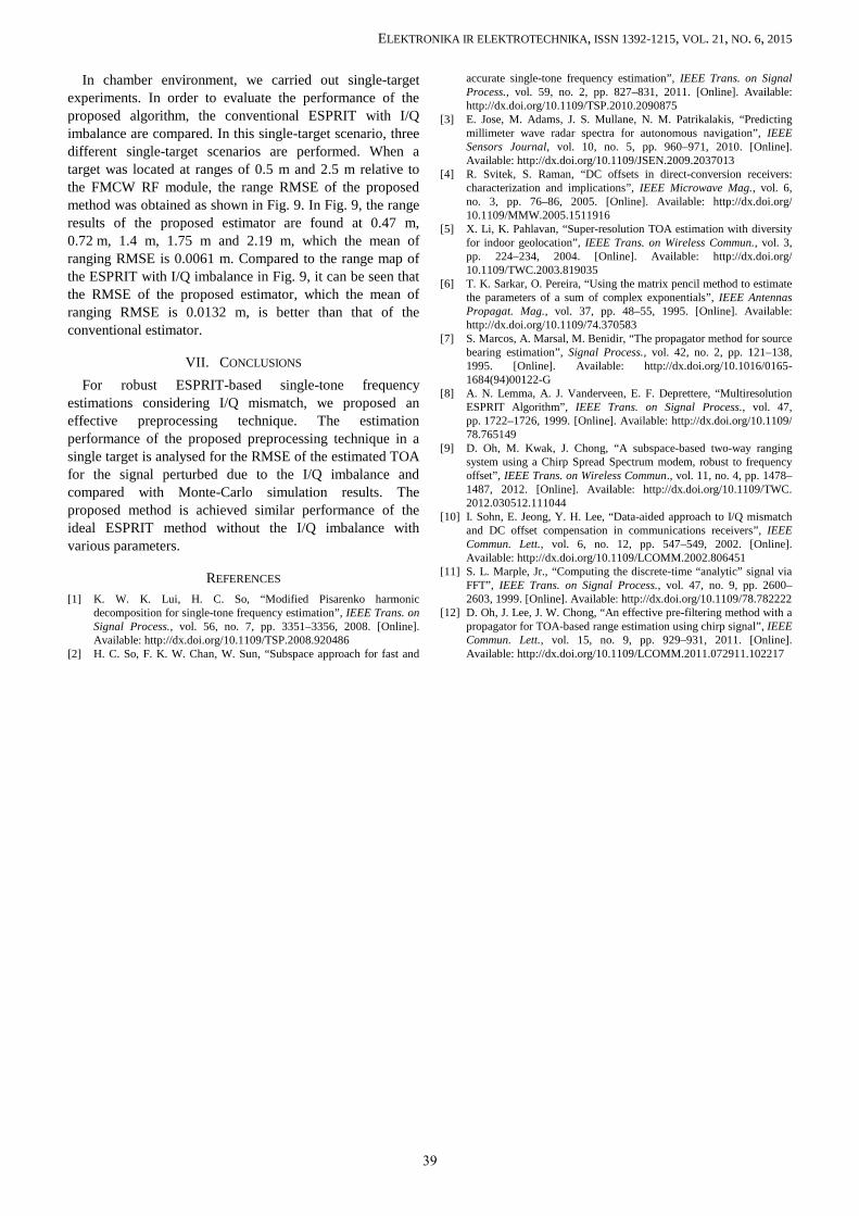
In chamber environment, we carried out single-targetexperiments. In order to evaluate the performance of theproposed algorithm, the conventional ESPRIT with I/Qimbalance are compared. In this single-target scenario, threedifferent single-target scenarios are performed. When atarget was located at ranges of 0.5 m and 2.5 m relative tothe FMCW RF module, the range RMSE of the proposedmethod was obtained as shown in Fig. 9. In Fig. 9, the rangeresults of the proposed estimator are found at 0.47 m,0.72 m, 1.4 m, 1.75 m and 2.19 m, which the mean ofranging RMSE is 0.0061 m. Compared to the range map ofthe ESPRIT with I/Q imbalance in Fig. 9, it can be seen thatthe RMSE of the proposed estimator, which the mean ofranging RMSE is 0.0132 m, is better than that of theconventional estimator.
VII. CONCLUSIONS
For robust ESPRIT-based single-tone frequencyestimations considering I/Q mismatch, we proposed aneffective preprocessing technique. The estimationperformance of the proposed preprocessing technique in asingle target is analysed for the RMSE of the estimated TOAfor the signal perturbed due to the I/Q imbalance andcompared with Monte-Carlo simulation results. Theproposed method is achieved similar performance of theideal ESPRIT method without the I/Q imbalance withvarious parameters.
REFERENCES
[1] K. W. K. Lui, H. C. So, “Modified Pisarenko harmonicdecomposition for single-tone frequency estimation”, IEEE Trans. onSignal Process., vol. 56, no. 7, pp. 3351–3356, 2008. [Online].Available: http://dx.doi.org/10.1109/TSP.2008.920486
[2] H. C. So, F. K. W. Chan, W. Sun, “Subspace approach for fast and
accurate single-tone frequency estimation”, IEEE Trans. on SignalProcess., vol. 59, no. 2, pp. 827–831, 2011. [Online]. Available:http://dx.doi.org/10.1109/TSP.2010.2090875
[3] E. Jose, M. Adams, J. S. Mullane, N. M. Patrikalakis, “Predictingmillimeter wave radar spectra for autonomous navigation”, IEEESensors Journal, vol. 10, no. 5, pp. 960–971, 2010. [Online].Available: http://dx.doi.org/10.1109/JSEN.2009.2037013
[4] R. Svitek, S. Raman, “DC offsets in direct-conversion receivers:characterization and implications”, IEEE Microwave Mag., vol. 6,no. 3, pp. 76–86, 2005. [Online]. Available: http://dx.doi.org/10.1109/MMW.2005.1511916
[5] X. Li, K. Pahlavan, “Super-resolution TOA estimation with diversityfor indoor geolocation”, IEEE Trans. on Wireless Commun., vol. 3,pp. 224–234, 2004. [Online]. Available: http://dx.doi.org/10.1109/TWC.2003.819035
[6] T. K. Sarkar, O. Pereira, “Using the matrix pencil method to estimatethe parameters of a sum of complex exponentials”, IEEE AntennasPropagat. Mag., vol. 37, pp. 48–55, 1995. [Online]. Available:http://dx.doi.org/10.1109/74.370583
[7] S. Marcos, A. Marsal, M. Benidir, “The propagator method for sourcebearing estimation”, Signal Process., vol. 42, no. 2, pp. 121–138,1995. [Online]. Available: http://dx.doi.org/10.1016/0165-1684(94)00122-G
[8] A. N. Lemma, A. J. Vanderveen, E. F. Deprettere, “MultiresolutionESPRIT Algorithm”, IEEE Trans. on Signal Process., vol. 47,pp. 1722–1726, 1999. [Online]. Available: http://dx.doi.org/10.1109/78.765149
[9] D. Oh, M. Kwak, J. Chong, “A subspace-based two-way rangingsystem using a Chirp Spread Spectrum modem, robust to frequencyoffset”, IEEE Trans. on Wireless Commun., vol. 11, no. 4, pp. 1478–1487, 2012. [Online]. Available: http://dx.doi.org/10.1109/TWC.2012.030512.111044
[10] I. Sohn, E. Jeong, Y. H. Lee, “Data-aided approach to I/Q mismatchand DC offset compensation in communications receivers”, IEEECommun. Lett., vol. 6, no. 12, pp. 547–549, 2002. [Online].Available: http://dx.doi.org/10.1109/LCOMM.2002.806451
[11] S. L. Marple, Jr., “Computing the discrete-time “analytic” signal viaFFT”, IEEE Trans. on Signal Process., vol. 47, no. 9, pp. 2600–2603, 1999. [Online]. Available: http://dx.doi.org/10.1109/78.782222
[12] D. Oh, J. Lee, J. W. Chong, “An effective pre-filtering method with apropagator for TOA-based range estimation using chirp signal”, IEEECommun. Lett., vol. 15, no. 9, pp. 929–931, 2011. [Online].Available: http://dx.doi.org/10.1109/LCOMM.2011.072911.102217
39